Article

Enhanced UV Light Emission by Core-Shell Upconverting Particles Powering up TiO2 Photocatalysis in Near-Infrared Light

by
Agnieszka Jarosz-Duda
,
Paulina O’Callaghan
,
Joanna Kuncewicz
*,
Przemysław Łabuz
and
Wojciech Macyk
Jagiellonian University, Faculty of Chemistry, Gronostajowa 2, 30-387 Kraków, Poland
*
Author to whom correspondence should be addressed.
Submission received: 12 January 2020 / Revised: 12 February 2020 / Accepted: 13 February 2020 / Published: 15 February 2020

Abstract

:
The core-shell NaYb0.99F4:Tm0.01@NaYF4 upconverting particles (UCPs) with a high UV emission to apply in NIR-driven photocatalysis were synthesized. The influence of the Yb3+ doping concentration in NaYxF4:Yb0.99−xTm0.01 core particles, and the role of the NaYF4 shell on the upconversion emission intensity of the UCPs were studied. The absorption of NIR light by the obtained UCPs was maximized by increasing the Yb3+ concentration in the core, reaching the maximum for Y3+-free particles (NaYb0.99F4:Tm0.01). Additionally, covering the NaYb0.99F4:Tm0.01 core with a protective layer of NaYF4 minimized the surface luminescence quenching, which significantly improved the efficiency of upconversion emission. The high intensity of the UV light emitted by the NaYb0.99F4:Tm0.01@NaYF4 under NIR irradiation resulted in a high photocatalytic activity of TiO2 (P25) mixed with the synthesized material.

1. Introduction

Photocatalysis is a feasible solution for the emerging environmental and economic issues of humankind. It can be used for water treatment, air purification, and hydrogen production powered only by the sunlight [1,2,3]. Most of the solar radiation that reaches the Earth’s surface lies within the visible and infrared region. However, conventional photocatalysts, such as TiO2 or ZnO, while cheap, non-toxic, and chemically stable, absorb only ultraviolet (UV) light, which constitutes less than 5% of the energy received from the Sun [4]. In order to extend their photocatalytic activity for visible light, several modifications have been utilized, such as noble metal deposition, transition metal doping, or photosensitization [5,6,7,8,9]. In the case of the infrared light utilization, one of the most effective approaches is to use lanthanide-doped materials that are able to harvest near-infrared (NIR) photons and convert them into UV and visible light [10]. Therefore, the upconverted light can be utilized to excite TiO2 and trigger the photocatalytic reaction. However, the photocatalytic systems based on the upconverting particles (UCPs) suffer from a low efficiency [11]. This is because the upconversion (UC) is a multiphoton nonlinear process that requires high power density of the incident light and is sensitive to any luminescence quenching and cross de-excitation [12,13]. Thus, much effort is put into research to increase the efficiency of the UC processes occurring in materials suitable for photocatalytic applications.
One of the most efficient mechanisms of UC is the energy transfer upconversion (ETU) process (Figure 1a), which engages two different neighboring ions in energy transfer. The first ion, known as a sensitizer (S), is excited by a pump photon to its E1(S) state. Then, it transfers its harvested energy non-radiatively to the E1(A) level of the ion 2, called an activator (A). Absorption of the next photon results in population of a higher-energy E2(A) level of the ion 2. Emission occurs from this level, while the ion 1 relaxes to its ground state G(S). The most commonly chosen UCPs are the NaYF4 crystals doped with the optically active lanthanide ions. Such materials are characterized by low phonon energies and favorable distances between lanthanide ions, which promote high efficiencies of UC. In our work, an NaYF4 matrix with Yb3+ ions as sensitizers and Tm3+ ions as activators have been selected. Tm3+ ions were chosen due to their UV emission peaks (Figure 1b), which overlap with the TiO2 optical bandgap. Yb3+ ions are the most widely used sensitizers in lanthanide-doped UCPs [14]. Due to the simple energy level structure, they are insensitive to the concentration quenching; therefore, Yb3+-doping concentrations in NaYF4-based UCPs are usually higher than 20%. However, highly doped NaYF4 materials, including a complete substitution of Y3+ with Yb3+ ions, are rarely investigated. In this work, we demonstrate the influence of the molar concentration of the Yb3+ ions (from 29% to 99%) in the structure of the core particles on the emission intensity of the upconverting particles.
The UC emission band’s intensities and their ratios depend strongly not only on the concentration of the sensitizer or activator ions, but also on the efficiency of quenching on high-energy oscillators, such as surface defects, capping ligands, and solvent molecules. These processes become more significant for the particles with a high surface-to-volume ratio. An effective strategy for improving the luminescent properties of UCPs is to grow a protective shell around the core-particle to reduce a non-radiative energy dissipation. In the case of core–shell structures of UCPs, the emission centers are spatially isolated from the surface quenchers. The use of homogeneous inert coating without any sensitizer or activator ions also prevents undesirable energy-migration processes between active ions in the core and the shell. As shown in the work of Mai et al., an optically inactive NaYF4 shell deposited on a luminescent NaYF4:Yb,Er core enhanced the upconversion luminescence intensity [15]. We have investigated the influence of the NaYF4 coating on the emission intensity of the NaYb0.99F4:Tm0.01 upconverting particles and the resulting photocatalytic activity of the TiO2 (P25) mixed with the core and core–shell materials upon NIR irradiation.

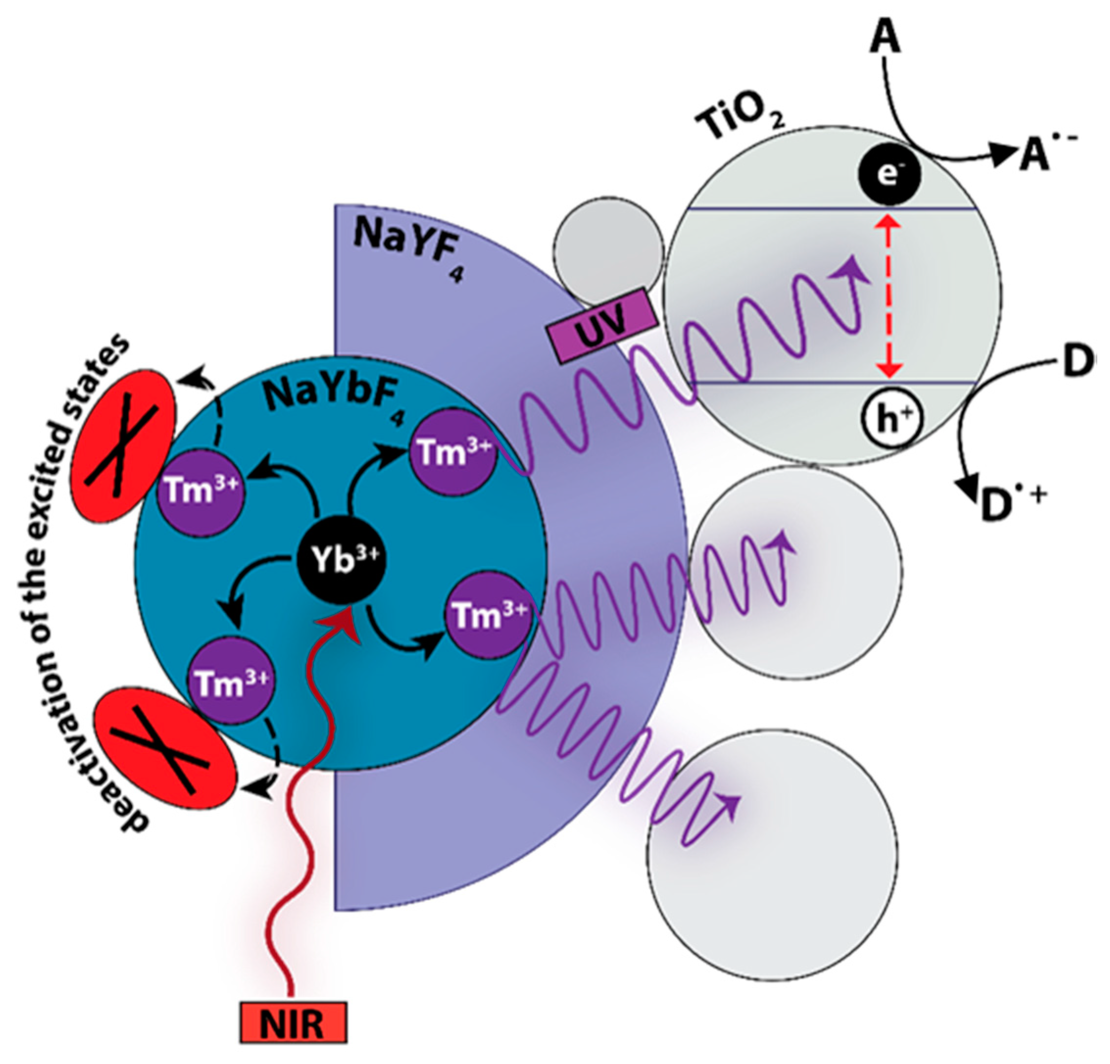
2. Results and Discussion

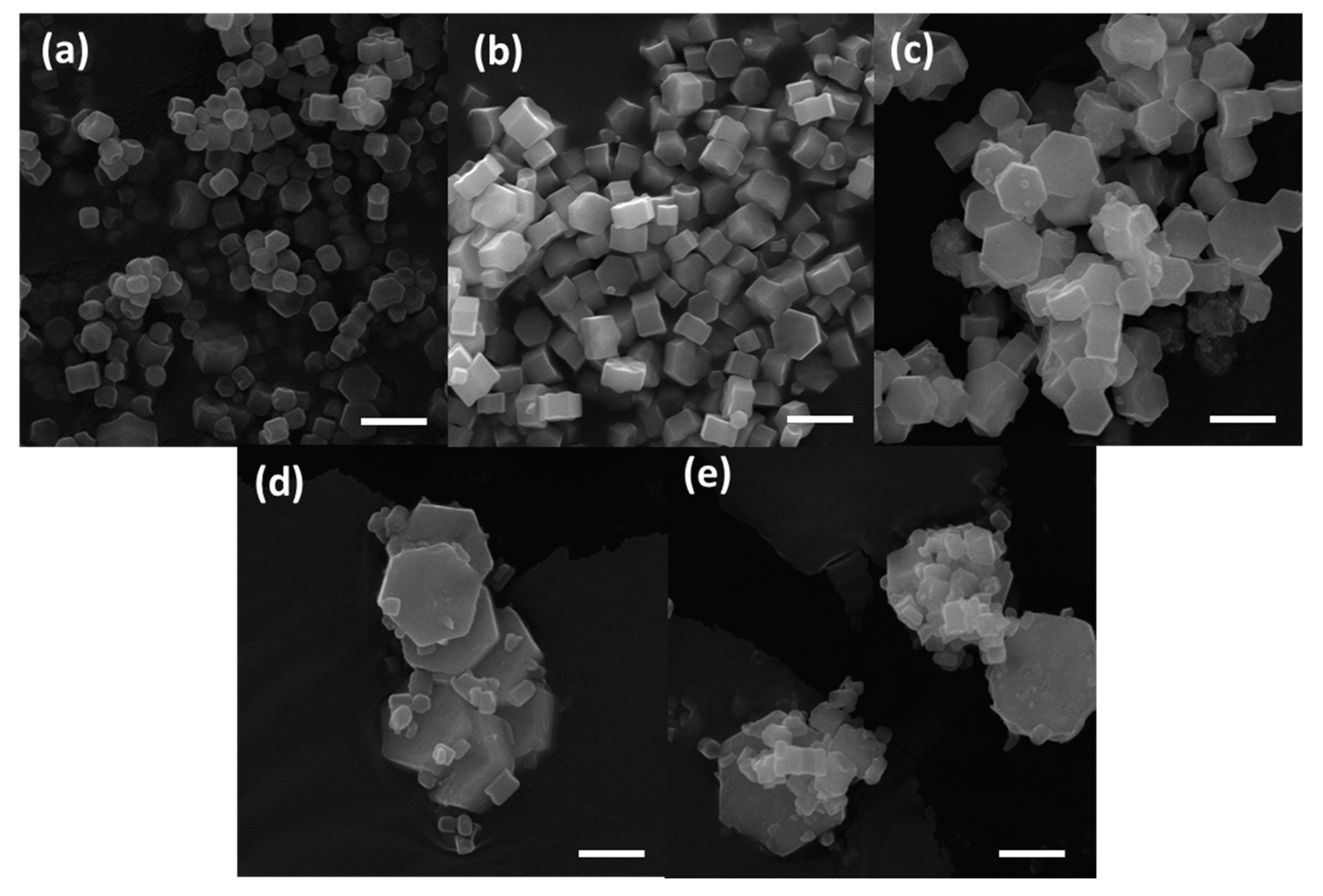
2.1. Morphology and Elemental Analysis

The NaYxF4:Yb0.99−xTm0.01 crystals with molar ratios of Y:Yb:Tm at 70:29:1, 50:49:1, 20:69:1, and 0:99:1 were obtained. All materials were white powders before and after calcination. The scanning electron microscopy (SEM) images (Figure 2) show that the synthesized materials crystallized mostly in the shape of hexagonal prisms, ranging in size from 0.25 to 1.5 micrometers with an increasing Yb3+ content. It can also be observed that the increasing amount of Yb3+ leads to the formation of more polydisperse particles. Apart from the large hexagonal prisms, a fraction of small nanoparticles can be found in the NaY0.3F4:Yb0.69Tm0.01 sample. NaYb0.99F4:Tm0.01 consists of very large hexagonal prisms and small cubes, which suggest the formation of the crystals in two crystallographic phases: hexagonal and cubic, which is further confirmed by the powder X-ray diffraction (XRD).
The energy-dispersive X-ray spectroscopy (EDX) measurements (Figure 3) reveal that the samples consist of Na, F, Yb, and Y elements. For the core-shell sample, yttrium is found in both large and small crystals. The presence of the Au peaks is due to the preparation method of the samples for the SEM analysis. The lack of the Tm peak, however, is attributed to the concentration of this element being below the detection limit.

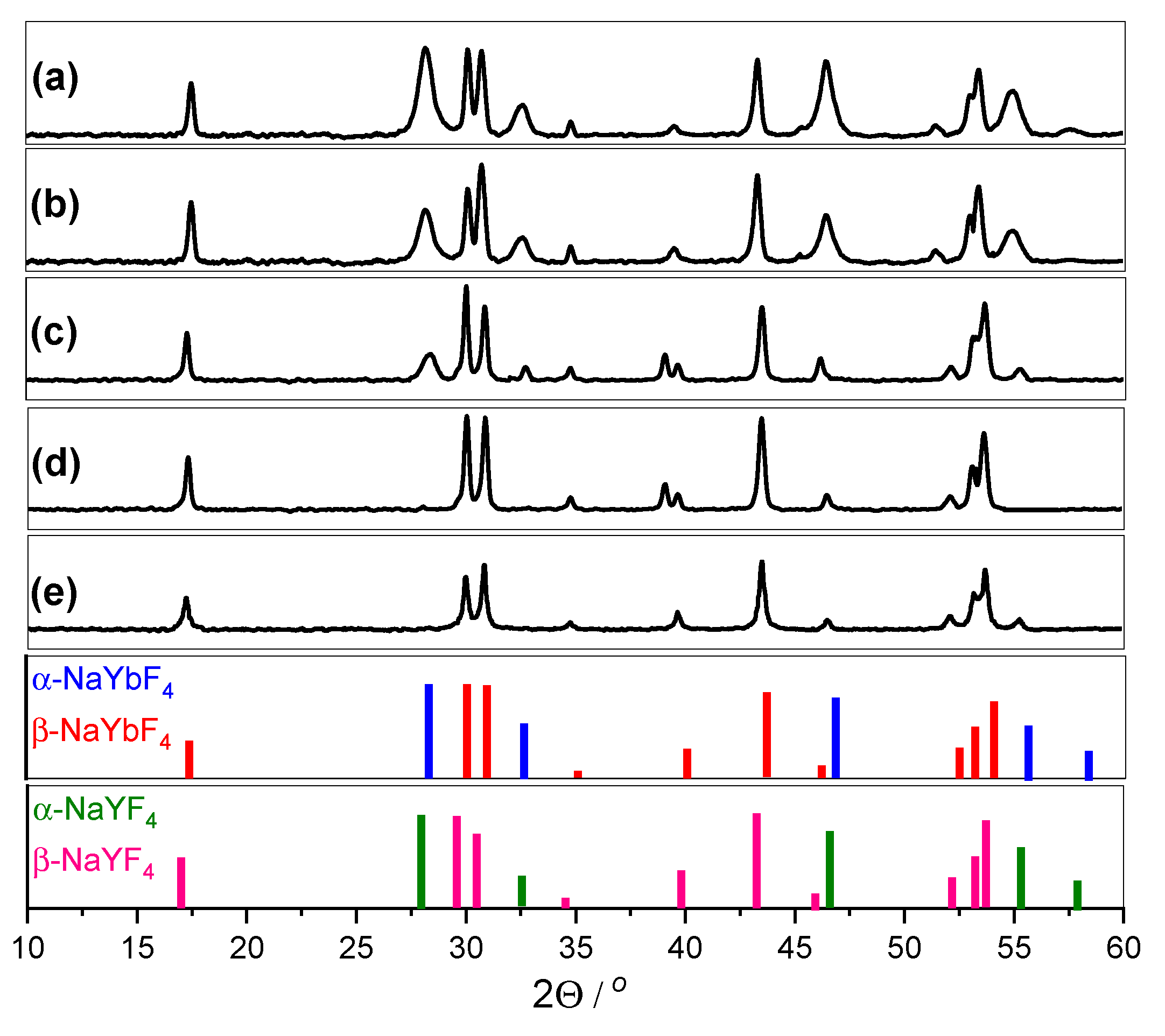
2.2. Structural Analysis—XRD

The crystal structures of sodium lanthanide fluorides (NaLnF4) can exist in two polymorphic forms—cubic α and hexagonal β phases—depending on the synthesis conditions. The XRD analysis has shown that the samples with high Yb3+ concentrations are composed of mixed cubic and hexagonal phases of NaYbF4 (according to #77-2043 and #27-1427 files from the JCPDS (The Joint Committee on Powder Diffraction Standards) database, respectively) (Figure 4). With decreasing Yb3+ content, the peaks from the cubic phase disappear gradually. The pure hexagonal phase of NaYbF4 nanocrystals exists at the Yb3+ doping concentrations below 50%. The peaks of the cubic phase are wider than the ones of the hexagonal phase, indicating the smaller size of the cubic phase crystals. Therefore, for the phosphors with high Yb3+ content, we observe crystallization of two fractions of particles: large prisms in the hexagonal phase and small cubes in the cubic phase.

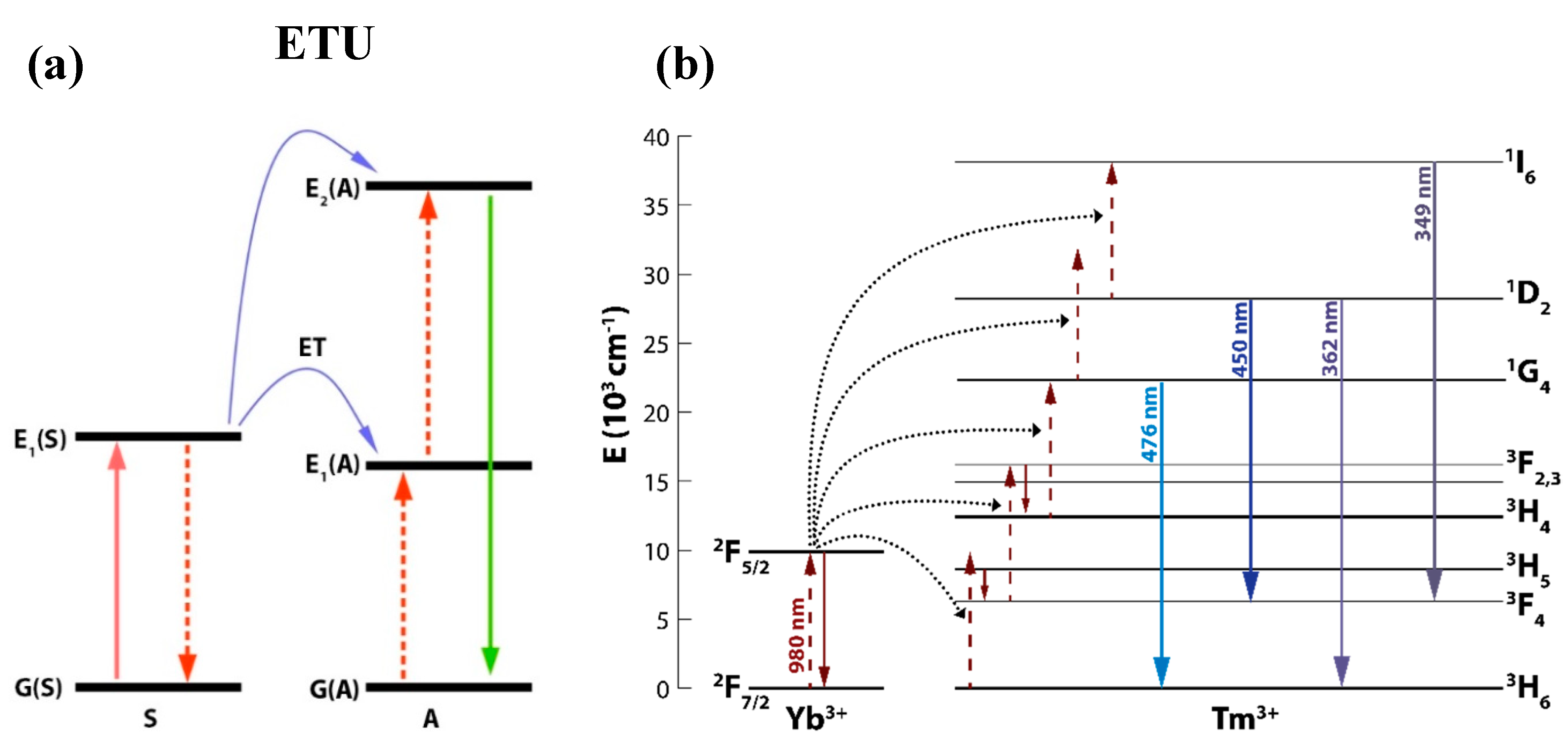
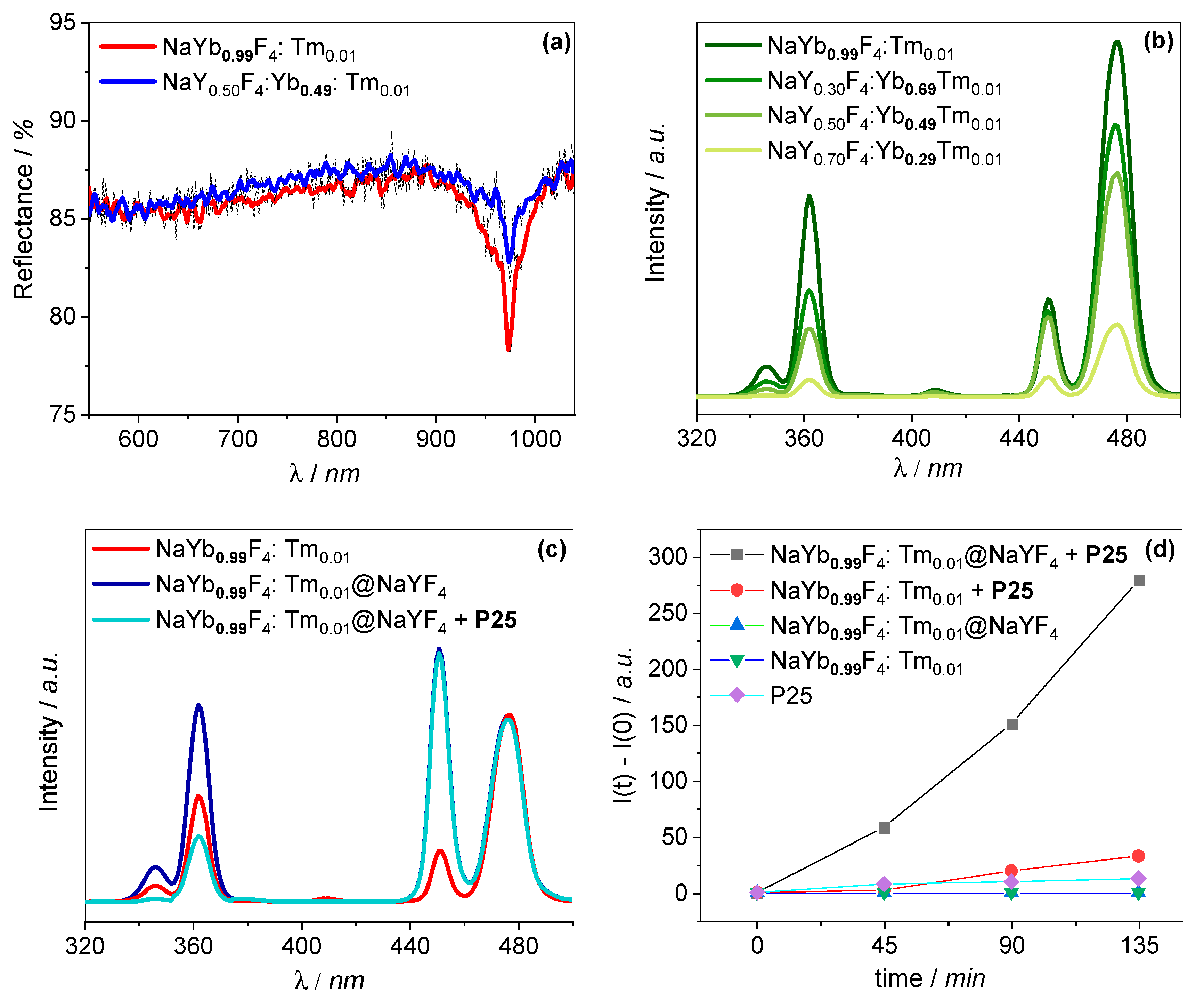
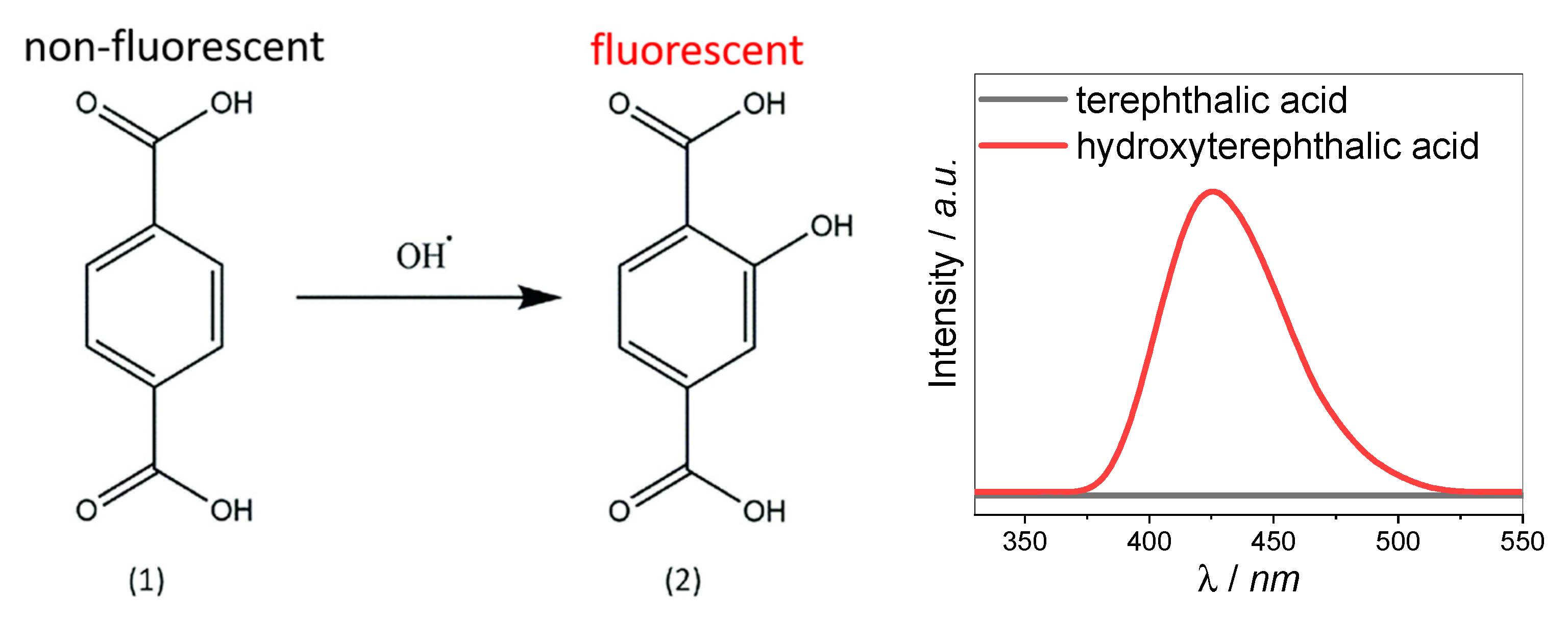
2.3. Spectroscopic Analysis

The NaYF4 crystals doped with the Yb3+–Tm3+ ion pair emit light from UV and visible range under a 980 nm laser excitation (1 W output power), as shown in Figure 5b,c. The UV emission peaks with maxima at 349 and 362 nm are attributed to the 1I63F4 (induced by the five-photon UC process) and 1D23H6 (induced by the four-photon UC process) transitions of Tm3+ ions, respectively. The two blue emission peaks centered at 450 nm and 476 nm are created in four- and three-photon processes and correspond to the 1D23F4 and 1G43H6 transitions of Tm3+ ions, respectively. Figure 5b presents the emission spectra of the NaYxF4:Yb0.99−xTm0.01 crystals with different Yb3+ doping concentrations. This shows that the intensity of both the UV and Vis emission bands increases with the increasing Yb3+ doping in the crystals. By the increasing concentration of ytterbium ions, the number of absorbing centers in each crystal is enlarged. The reflectance spectra of these materials (Figure 5a) show that a narrow peak at 976 nm, originating from the Yb3+ absorption, has a higher intensity for the sample with 99% of Yb3+ than for the one with 49% of Yb3+ content. Therefore, in highly Yb3+-doped materials, more photons are absorbed and transferred onto the activator’s energy levels than in the less-doped particles. This results in a higher upconversion emission intensity, especially for the peaks originating from the multiphoton processes. The luminescence intensity of the NaYb0.99F4:Tm0.01 crystals is the strongest. For this reason, NaYb0.99F4:Tm0.01 crystals were chosen for further coating with the inert NaYF4 shell. After depositing the NaYF4 shell on the surface of the NaYb0.99F4:Tm0.01 crystals, the size of the particles slightly changed: both the prisms and cubes crystals grew larger (Figure 2e). The XRD pattern of the core-shell particles (Figure 4a) shows that the sample consists of both cubic and hexagonal crystals, with a slightly higher content of the cubic phase in comparison to the core particles. This may indicate the predominance of this phase in the structure of NaYF4. No changes in the XRD peaks’ positions can be observed, suggesting no substitution of the Yb3+ by Y3+. However, the lattice parameters of NaYbF4 and NaYF4 are very similar (Figure 4); therefore, the changes may be too small to be distinguished when measuring with chosen parameters.
There is no direct evidence of the existence of the NaYF4 shell. However, the EDX analysis performed using an electron beam of various intensities shows that the Yb3+/Y3+ ion’s ratio significantly increases with the penetration depth of the electron beam (Supplementary Information, Figure S1). Moreover, the deposition of the NaYF4 shell strongly improved the efficiency of the multi-photon UC processes observed for NaYb0.99F4:Tm0.01 (Figure 5c), which could not be explained by a slight change in the crystallite sizes, nor by a doping process. In particular, a significant increase of the emission intensity at 362 nm and 450 nm can be observed, which proves the beneficial role of the protective layer in decreasing the surface luminescence quenching. The emission spectrum of the core-shell particles mixed with P25 was also recorded (Figure 5c). This shows that in the presence of TiO2 the UV emission peaks of the core-shell UCPs significantly decreased compared to the visible emission peaks. The UV light emitted by the UCPs overlapped with the optical bandgap of titania (3.2 eV), what suggests that the attenuation of the 349 and 362 nm peaks originates from the absorption of light by the surrounding P25. The photocatalytic activity measurements further confirm these findings (Figure 5d).

2.4. Photocatalytic Activity

The production of the HO radicals under NIR light irradiation was investigated in order to establish the photocatalytic performance of the mixture of upconverting particles with TiO2. Because of their strong oxidation ability, these reactive species are often considered to be responsible for the degradation of organic molecules. To verify the generation of HO, terephthalic acid (TA) hydroxylation was investigated (Scheme 1) [16]. The TA itself does not show any fluorescence; however, it reacts with the hydroxyl radicals produced in the photocatalytic redox reaction to form hydroxyterephthalic acid (TAOH), which emits light at about 425 nm when excited with UV light. For used experimental conditions (i.e.,: temperature, pH, and oxygen concentration) the intensity of the TAOH fluorescence is proportional to the concentration of generated HO radicals, and TAOH should be the only fluorescent product of the reaction [16,17]. As shown in Figure 5d, the photoluminescence intensity of TAOH increases in the presence of the UCPs mixed with P25 with NIR irradiation time. The experiment proves the efficient absorption of the UV light (emitted by NaYb0.99F4:Tm0.01 and NaYb0.99F4:Tm0.01@NaYF4) by TiO2. The mixture containing the core-shell material produces a significantly higher amount of HO radicals in comparison to the systems with the materials of core-only structure. A negligible hydroxyl radical generation was detected in the absence of either the photocatalyst or UCPs. The proposed mechanism of a NIR-driven photocatalytic reaction in the presence of the synthesized core and core-shell materials is presented in Figure 6. The sensitizer Yb3+ ions absorb NIR photons at 980 nm. Then, the harvested energy is transferred non-radiatively to the activator Tm3+ ions, which subsequently emit UV-Vis light. The UV emission can then be utilized for TiO2 excitation, leading to generation of the electrons and holes in the conduction and valence bands of the semiconductor, respectively. The photogenerated charges can participate in the reduction and oxidation reactions at the surface of the photocatalyst. The interfacial electron transfer processes involve the molecules of an electron acceptor (A) (e.g., oxygen) and a donor (D) (e.g., H2O or OH), creating their reduced and oxidized forms. In this work, the generation of HO radicals, which may be created upon the one-electron oxidation of the adsorbed H2O molecules or OH oins by the photogenerated holes, has been analyzed. The efficiency of the TiO2 excitation process depends on the upconversion photoluminescence intensity. In this case, coating with the inert NaYF4 shell enhances significantly emission in the UV range. The high-energy oscillators at the surface of the uncoated core particles, such as defects and solvent molecules, cause the deactivation of the excited Tm3+ states, resulting in the low efficiency of the upconversion process.

3. Materials and Methods

3.1. Materials

Ytterbium chloride hexahydrate (YbCl3∙6H2O, 99.99%, Sigma Aldrich, St. Louis, MO, USA), yttrium chloride hexahydrate (YCl3∙6H2O, 99.99%, Sigma Aldrich, St. Louis, MO, USA), thulium chloride anhydrous (TmCl3, 99.99%, Sigma Aldrich, St. Louis, MO, USA), sodium hydroxide (NaOH, 99.8%, POCh, Gliwice, Poland), oleic acid (OA, 99.9%, Fluka, Buchs, Switzerland), 1-octadecene (ODE, 90%, Sigma Aldrich, St. Louis, MO, USA), ammonium fluoride (NH4F, Acros, Geel, Belgium), ethyl alcohol (EtOH, POCh, Gliwice, Poland), cyclohexane (Sigma Aldrich, St. Louis, MO, USA), hydrochloric acid (HCl, POCh, Gliwice, Poland), terephthalic acid (TA, Aldrich, St. Louis, MO, USA), and titanium(IV) oxide (P25, Evonik, Essen, Germany) were used as received without further purification.

3.2. Synthesis of NaYxF4:Yb0.99−xTm0.01 Microcrystals

The NaYxF4:Yb0.99−xTm0.01 materials were prepared by a solvothermal method. In a typical process, 0.36 g NaOH were transferred to a Teflon autoclave lining filled with 2.4 mL ethanol and 0.6 mL distilled water and stirred until a homogeneous solution was obtained. Vigorous stirring was continued throughout the preparation of the reaction mixture. Then, 6 mL of oleic acid was added to the solution. After 20 min, a total volume of 1.5 mL of 0.2 M rare-earth (RE) chlorides solution (YCl3, YbCl3, and TmCl3 with molar ratios of 70:29:1, 50:49:1, 30:69:1, or 0:99:1) was added dropwise to the reaction vessel. The amount of the added 0.1 M NH4F was fixed at 1.2 mL for obtaining particles with an F to RE3+ molar ratio of 4:1.
The Teflon lining with the resulting solution was then placed in a stainless steel autoclave, sealed, and maintained at 190 °C for 12 h. The synthesized particles were washed several times with ethanol and cyclohexane to remove the remaining oleic acid and possible impurities formed during the synthesis. The purified particles were dried at 60 °C for 12 h.

3.3. Synthesis of the Core-Shell NaYb0.99F4:Tm0.01@NaYF4 Crystals

The 0.36 g of NaOH was transferred to a Teflon vessel. Then, 2.4 mL ethanol was added to the vessel and mixed until a homogeneous solution was obtained. Vigorous stirring was continued throughout the entire preparation of the reaction mixture. The 6 mL of oleic acid was added to the mixture. After 20 min, 1.5 mL of 0.2 M YCl3 solution was added, along with 25 mg of the core NaYb0.99F4:Tm0.01 particles dispersed in 0.6 mL of distilled water and 1.8 mL of 0.1 M aqueous NH4F solution. The Teflon linings were then placed in stainless steel autoclaves. The syntheses were carried out at 190 °C for 12 h. After the reactors were naturally cooled to room temperature, the solutions were poured into falcons, rinsed with ethanol to precipitate synthesized nanoparticles, and centrifuged at 5000 rpm for 20 min. The supernatant was removed and the particles were washed several times with ethanol and distilled water to get rid of residual oleic acid and any impurities generated in the synthesis process. Then, the oleic acid was removed from the surface of the particles in order to obtain the ligand-free water-dispersible microcrystals. For this purpose, a modified literature procedure reported by Bogdan et al. [18] was used. In a typical experiment, oleate-capped particles were dispersed in 4 mL of 2 M HCl solution and sonicated for 15 min to remove surface ligands. The products were washed with ethanol and water three times, collected by centrifugation and dried at 60 °C. In order to improve the crystallinity of the materials and remove any organic impurities, the obtained powders were calcined in the oven at 400 °C for 3 h.

3.4. Characterization

The crystal phase content of the synthesized particles was determined using a MiniFlex 600 (Rigaku, Tokyo, Japan ) X-ray diffractometer equipped in a CuKα nickel-filtered source lamp (λ = 1.54 Å] operating at 40 kV voltage. The scan range was 3–70° 2θ with a step of 0.02° and the rate of 10° per minute.
The size, morphology, and elemental composition were analyzed using a Vega 3 LM (Tescan, Brno, Czech Republic) scanning electron microscope equipped with an LaB6 cathode and EDX detector (10 mm2 x-act SDD detector, Oxford Instruments, Abingdon, UK ) operating at 20 and 30 kV voltage. The samples were prepared by spreading the powders on the carbon tape and coating them with a thin layer of gold (Quorum Q150R, Laughton, UK).
A Perkin Elmer LS55 fluorescence spectrometer was used to record the luminescence spectra of hydroxyterephthalic acid. The excitation wavelength was set to 315 nm and the emission was measured in the range of 300–600 nm. The measurements were performed in quartz cuvettes with a pathlength of 5 mm.
The diffuse reflectance spectra (DRS) were recorded by a UV-Vis Lambda 12 (Perkin Elmer, Waltham, MA, USA) spectrometer equipped with a 5 cm diameter integrating sphere. The samples were ground in the agate mortar with barium sulphate in the weight ratio of 1:50. BaSO4 was also used as a reference.
The upconversion luminescence spectra were obtained using a 980 CW diode laser (LambdaWave, Wrocław, Poland) with a light power of 0.84 W and a beam size of approximately 8 mm2. The results were recorded using a SPEX Fluorolog 3.22 (Horiba, Kyoto, Japan) spectrofluorometer.

3.5. Photocatalytic Measurements

The photocatalytic activity of the UCPs/P25 systems was analyzed by measuring the fluorescence intensity of hydroxyterephthalic acid (TAOH) formed in the process of terephthalic acid hydroxylation. For each experiment, 6 mg of UCPs was mixed with 1.25 mL of 0.4 mg/mL P25 aqueous suspension. Then, 1.25 mL of the 0.6 mM TA solution in 10 mM NaOH was added. The prepared suspensions were irradiated with the 980 nm laser diode (measured power of light: 10.5 W cm−2, beam size: 8 mm2). Every 45 min, 0.5 mL of the suspensions were collected and centrifuged, and the emission spectra of the supernatants were recorded (λex = 315 nm). The concentration of the generated hydroxyl radicals was proportional to the intensity of the fluorescence band of TAOH (λmax = 425 nm).

4. Conclusions

NaYxF4:Yb0.99−xTm0.01 upconverting particles with a variable Y3+ to Yb3+ ratio were synthesized. The crystals with the highest upconversion photoluminescence intensity were chosen to be coated with a protective NaYF4 layer in order to assess the outer shell influence on their luminescent properties. The results revealed that P25, in the presence of the microcrystals with the highest concentration of Yb3+ ions coated with the inert shell, exhibited the highest HO generation efficiency under the NIR irradiation. The increased photocatalytic activity can be attributed to the strengthened upconversion photoluminescence of the core–shell NaYb0.99F4:Tm0.01@NaYF4 particles compared to the core-only NaYb0.99F4:Tm0.01 material. The conducted experiments proved that the increase of the concentration of sensitizer ions (Yb3+) that absorb NIR light at 980 nm leads to a significant enhancement of UV-Vis emission. We also confirmed that coating the luminescent NaYb0.99F4:Tm0.01 core with a protective NaYF4 layer intensifies the upconversion efficiency, and, hence, improves the UCPs-assisted TiO2 photocatalytic activity under NIR irradiation.

Supplementary Materials

The following are available online at https://0-www-mdpi-com.brum.beds.ac.uk/2073-4344/10/2/232/s1, Figure S1: EDX analysis of the NaYb0.99F4:Tm0.01@NaYF4 sample with different beam intensities (BI). The Yb3+/Y3+ ions ratio is significantly increasing with the penetration depth, what indicates higher content of Y3+ ions at the surface of studied material.

Author Contributions

Conceptualization, A.J.-D., P.O.C., J.K. and W.M.; methodology, A.J.-D., P.O.C., J.K. and P.Ł.; validation, J.K., P.Ł. and W.M.; formal analysis, A.J.-D. and P.O.C.; investigation, A.J.-D. and P.O.C.; resources, W.M.; data curation, A.J.-D. and P.O.C.; writing—original draft preparation, A.J.-D. and P.O’C; writing—review and editing, J.K., P.Ł. and W.M.; visualization, A.J.-D. and P.O.C.; supervision, J.K., P.Ł. and W.M.; funding acquisition, J.K. and W.M. All authors have read and agreed to the published version of the manuscript.

Funding

This research was funded by the Foundation of Polish Science within the TEAM project (POIR.04.04.00-00-3D74/16).

Conflicts of Interest

The authors declare no conflict of interest. The funders had no role in the design of the study; in the collection, analyses, or interpretation of data; in the writing of the manuscript, or in the decision to publish the results.

References

  1. Nakata, K.; Fujishima, A. TiO2 photocatalysis: Design and applications. J. Photochem. Photobiol. C 2012, 13, 169–189. [Google Scholar] [CrossRef]
  2. Hoffmann, M.R.; Martin, S.T.; Choi, W.; Bahnemann, D.W. Environmental applications of semiconductor photocatalysis. Chem. Rev. 1995, 95, 69–96. [Google Scholar] [CrossRef]
  3. Mills, A.; Davies, R.H.; Worsley, D. Water purification by semiconductor photocatalysis. Chem. Soc. Rev. 1993, 22, 417–425. [Google Scholar] [CrossRef]
  4. Sang, Y.; Liu, H.; Umar, A. Photocatalysis from UV/Vis to Near-Infrared Light: Towards Full Solar-Light Spectrum Activity. Chem. Cat. Chem. 2015, 7, 559–573. [Google Scholar]
  5. Macyk, W.; Szaciłowski, K.; Stochel, G.; Buchalska, M.; Kuncewicz, J.; Łabuz, P. Titanium (IV) complexes as direct TiO2 photosensitizers. Coord. Chem. Rev. 2010, 254, 2687–2701. [Google Scholar] [CrossRef]
  6. Zhang, Q.; Yang, F.; Xu, Z.; Chaker, M.; Ma, D. Are lanthanide-doped upconversion materials good candidates for photocatalysis? Nanoscale Horiz. 2019, 4, 579–591. [Google Scholar] [CrossRef]
  7. Yoon, T.P.; Ischay, M.A.; Du, J. Visible light photocatalysis as a greener approach to photochemical synthesis. Nature Chem. 2010, 2, 527. [Google Scholar] [CrossRef]
  8. Kisch, H.; Macyk, W. Visible-light photocatalysis by modified titania. Chem. Phys. Chem. 2002, 3, 399–400. [Google Scholar] [CrossRef]
  9. Asahi, R.Y.O.J.I.; Morikawa, T.A.K.E.S.H.I.; Ohwaki, T.; Aoki, K.; Taga, Y. Visible-light photocatalysis in nitrogen-doped titanium oxides. Science 2001, 293, 269–271. [Google Scholar] [CrossRef] [PubMed]
  10. Auzel, F. Upconversion and anti-stokes processes with f and d ions in solids. Chem. Rev. 2004, 104, 139–174. [Google Scholar] [CrossRef] [PubMed]
  11. Yang, W.; Li, X.; Chi, D.; Zhang, H.; Liu, X. Lanthanide-doped upconversion materials: Emerging applications for photovoltaics and photocatalysis. Nanotechnology 2014, 25, 482001. [Google Scholar] [CrossRef] [PubMed]
  12. Altavilla, C. Upconverting Nanomaterials: Perspectives, Synthesis, and Applications; CRC Press: Boca Raton, FL, USA, 2016. [Google Scholar]
  13. Liu, X.; Yan, C.-H.; Capobianco, J.A. Photon upconversion nanomaterials. Chem. Soc. Rev. 2015, 44, 1299–1301. [Google Scholar] [CrossRef] [PubMed] [Green Version]
  14. Haase, M.; Schafer, H. Upconverting nanoparticles. Angew. Chem. Int. Ed. 2011, 50, 5808–5829. [Google Scholar] [CrossRef] [PubMed]
  15. Mai, H.X.; Zhang, Y.W.; Sun, L.D.; Yan, C.H. Highly efficient multicolor up-conversion emissions and their mechanisms of monodisperse NaYF4: Yb, Er core and core/shell-structured nanocrystals. J. Phys. Chem. C 2007, 20, 13721–13729. [Google Scholar] [CrossRef]
  16. Charbouillot, T.; Brigante, M.; Mailhot, G.; Maddigapu, P.R.; Minero, C.; Vione, D. Performance and selectivity of the terephthalic acid probe for OH as a function of temperature, pH and composition of atmospherically relevant aqueous media. J. Photochem. Photobiol. A 2011, 222, 70–76. [Google Scholar] [CrossRef]
  17. Matthews, R.W. The radiation chemistry of the terephthalate dosimeter. Radiat. Res. 1980, 83, 27–41. [Google Scholar] [CrossRef] [PubMed]
  18. Bogdan, N.; Vetrone, F.; Ozin, G.A.; Capobianco, J.A. Synthesis of ligand-free colloidally stable water dispersible brightly luminescent lanthanide-doped upconverting nanoparticles. Nano Lett. 2011, 11, 835–840. [Google Scholar] [CrossRef] [PubMed]
Figure 1. (a) The energy transfer upconversion (ETU) mechanism. ET – energy transfer, S – sensitizer, A – activator. (b) Schematic energy level diagram for the Yb3+–Tm3+ pair with transitions responsible for the UV and visible light emissions upon 980 nm excitation.
Catalysts 10 00232 g001
Figure 2. SEM images of the synthesized NaYxF4:Yb0.99−xTm0.01 with Yb3+ content of (a) 29%, (b) 49%, (c) 69%, (d) 99%, and (e) NaYb0.99F4:Tm0.01@NaYF4. The scale bar represents 1 μm.
Catalysts 10 00232 g002
Figure 3. The EDX spectra of (a) the core–shell NaYb0.99F4:Tm0.01@NaYF4, and (b) core NaYb0.99F4:Tm0.01 particles.
Catalysts 10 00232 g003
Figure 4. XRD patterns of (a) NaYb0.99F4:Tm0.01@NaYF4, (b) NaYb0.99F4:Tm0.01, (c) NaY0.3F4:Yb0.69Tm0.01, (d) NaY0.5F4:Yb0.49Tm0.01, and (e) NaY0.7F4:Yb0.29Tm0.01, with reference to hexagonal (β) and cubic (α) phases of NaYbF4 and NaYF4, according to #27-1427, #77-2043, #16-0334 and 77-2042 files from the JCPDS database, respectively.
Catalysts 10 00232 g004
Figure 5. (a) Diffuse reflectance spectra of chosen upconverting particles (UCPs). (b) Upconversion luminescence spectra of NaYF4 crystals doped with different amounts of Yb3+ ions (29%, 49%, 69%, and 99%), under 980 nm NIR excitation. (c) Upconversion emission spectra of the core, core-shell particles, and a mixture of the core-shell particles with P25. All spectra have been normalized to the same emission intensity at 476 nm. (d) Luminescence intensities of hydroxyterephthalic acid generated in the presence of the studied materials irradiated at 980 nm (λex = 315 nm, λem = 425 nm).
Catalysts 10 00232 g005
Figure 6. The proposed mechanism of the NIR-driven photocatalytic reaction in the presence of the examined core and core–shell upconverting particles (D denotes an electron donor, such as H2O or OH ions; A denotes an electron acceptor, such as O2).
Catalysts 10 00232 g006
Scheme 1. Scheme of the terephthalic acid (1) reaction with hydroxyl radicals, resulting in generation of hydroxyterephthalic acid (2), which emits light at about 425 nm when excited with 315 nm.
Catalysts 10 00232 sch001

