Review

Photocatalysis for Air Treatment Processes: Current Technologies and Future Applications for the Removal of Organic Pollutants and Viruses

Faculty of Engineering, Western University, Chemical Reactor Engineering Centre (CREC), 1151 Richmond Street, London ON N6A 5B9, Canada
*
Author to whom correspondence should be addressed.
Submission received: 16 July 2020 / Revised: 18 August 2020 / Accepted: 21 August 2020 / Published: 24 August 2020
(This article belongs to the Special Issue Commemorative Issue in Honor of Professor Hugo de Lasa)

Abstract

:
Photocatalysis for air treatment or photocatalytic oxidation (PCO) is a relatively new technology which requires titanium dioxide (TiO2) and a source of light (Visible or near-UV) to degrade pollutants contained in air streams. Present approaches for the photodegradation of indoor pollutants in air streams aim to eliminate volatile organic compounds (VOCs) and viruses, which are both toxic and harmful to human health. Photocatalysis for air treatment is an inexpensive and innovative green process. Additionally, it is a technology with a reduced environmental footprint when compared to other conventional air treatments which demand significant energy, require the disposal of used materials, and release CO2 and other greenhouse gases to the environment. This review discusses the most current and relevant information on photocatalysis for air treatment. This article also provides a critical review of (1) the most commonly used TiO2-based semiconductors, (2) the experimental syntheses and the various photocatalytic organic species degradation conversions, (3) the developed kinetics and computational fluid dynamics (CFD) and (4) the proposed Quantum Yields (QYs) and Photocatalytic Thermodynamic Efficiency Factors (PTEFs). Furthermore, this article contains important information on significant factors affecting the photocatalytic degradation of organic pollutants, such as reactor designs and type of photoreactor irradiation. Overall, this review describes state-of-the-art photocatalysis for air treatment to eliminate harmful indoor organic molecules, reviewing as well the potential applications for the inactivation of SARS-CoV2 (COVID-19) viruses.

Graphical Abstract

1. Introduction

The generation of indoor air pollution by biological and chemicals contaminants including viruses, particles, polycyclic aromatic hydrocarbons (PAHs), combustion products and volatile organic compounds (VOCs) is a public health and environmental concern [1,2,3]. These agents may increase the risk of developing nonspecific respiratory and neurologic symptoms, allergies, asthma and lung cancer [4]. Since we spend a significant amount of time (on average 90%) in enclosed spaces such as homes, factories, office buildings and transportation vehicles, it is important to continuously remove VOCs and viruses from indoor air atmospheres [5,6]. Thus, by implementing new green technologies such as photocatalysis for air treatment, one may be able to achieve VOC removal and virus inactivation. Moreover, this new green process could lead to major policy mandated regulations for indoor building environments, as well as the establishment of a well-founded risk analysis [7].
Photocatalysis is an efficient technique that uses light photons and semiconductor materials under ambient reaction conditions in order to achieve the complete degradation of organic pollutants [8]. Among the different types of semiconductors, titanium dioxide (TiO2) is by far one of the superior ones, given its high stability and photosensitivity, its high oxidation ability, its negligible toxicity and its low cost [9].
Photocatalytic reaction mechanisms for air treatment involve (a) light absorption, (b) the formation and separation of electron (e) and hole (h+) pairs, and (c) oxidation-reduction surface reactions, occurring between electrons (e) and adsorbed oxygen molecules (O2), which can produce superoxide radicals (O2). Subsequently, additional electron holes (h+) and water (H2O) molecules can generate hydroxyl radicals (OH). Thus, given that both O2- and OH radicals are powerful oxidants, they can mineralize harmful chemical species (i.e., VOCs) in air, converting them into CO2 and H2O, as later described in Figure 1 [2,10,11,12,13,14,15].
Although TiO2 semiconductors are promising, there are limitations preventing these photocatalysts from reaching their full potential. For example, TiO2 displays high (e) and (h+) charge recombination rates and a large energy band gap (EBG) of 3.2 eV with only a small fraction of the solar spectrum being able to be used in photocatalytic applications. In addition, the popular commercial DP25 photocatalyst displays a small specific surface area with individual particle agglomeration as a result of the strong interparticle forces [16]. However, by impregnating, doping, or co-doping TiO2 with metals such as iron (Fe), silver (Ag), palladium (Pd) and platinum (Pt) or non-metals like nitrogen (N), one can improve (a) the reduction of the TiO2 energy band gap (EBG < 3.2 eV), (b) the slowing of the (e)/(h+) recombination rate, and (c) the diminishing of the particle agglomeration [17,18]. Furthermore, through the use of a new photocatalyst synthesis utilizing a sol-gel method, larger TiO2 surface areas (50 m2/g < SBET ≤ 150 m2/g), morphologies (high porosity) and crystal structures (anatase dominant crystalline phase) can be obtained [11,19]. All these advancements with TiO2 photocatalysts are extremely important for the improvement of the process of photocatalysis and the extensive application of air treatment, both for VOCs conversion and airborne virus inactivation.
During the past few years, numerous photoreactor configurations for PCO (Photocatalytic Oxidation) have been reported in the literature, including fixed-bed reactors [20,21,22], fluidized-bed reactors [23,24], coated honeycomb monolith reactors [25,26,27], fixed powder layer reactors [28,29], annular coated reactors [11,30], and annular mesh-coated Venturi-reactors [2,12,13]. These reactor configurations are relevant given that they determine the PCO process. Their performance is affected by photocatalyst loading, the contacting between the fluid and the photocatalysts, as well as the uniformity, the type (near-UV or visible light) and the intensity of the irradiation field employed [9,14,31,32].
Nowadays, there is an increased need for PCO models based on chemical engineering principles. In this respect, a significant body of the research has focused on developing kinetic models in a variety of photocatalytic reactor configurations [8,31,33,34]. However, of similar importance is the study of computational fluid dynamics (CFD). The implementation of CFD has become possible thanks to the availability of powerful computers and the advancement of commercial CFD software. This allows numerical simulations for different reactor configurations and conditions relevant to industrial-scale applications [9,35,36,37]. It can be anticipated that CFD will help to design, develop, and analyze novel photocatalytic reactors (bench or pilot-scale) for air [2,12,14,38] or water treatment applications [39,40,41] and water splitting for hydrogen production [18,19,42].
This review also considers important photoreactor efficiency parameters such as Quantum Yields (QYs) and Photocatalytic Thermodynamic Efficiency Factors (PTEFs). A Quantum Yield describes the photoconversion of the organic pollutant in terms of the hydroxyl radicals consumed over the absorbed photons [10]. Furthermore, this efficiency factor has also been studied for water degradation [43] and hydrogen production [18,44]. To accurately evaluate this parameter, one has to measure macroscopic irradiation energy balances (MIEB) [15]. This strategy of assessing QYs and PTEFs allows the photocatalytic reactor to be operated under optimal conditions [8,15,16,43,44,45].
Thus, the present review is intended to report the most up-to-date research on air treatment for the removal of VOCs. Special emphasis has been given to new challenges, such as the inactivation of airborne viruses [46,47,48,49]. This review highlights research findings, research needs, and recent opportunities for innovation and commercialization of photocatalytic technologies for the inactivation of SARS-CoV2 (COVID-19) viruses.

2. Photocatalysts for Air Treatment

Commercial titanium dioxides (TiO2) such as Degussa P25 or Hombikat UV-100 have already been studied during the last five decades. These photocatalysts are commonly used for purification of water [50] and of indoor air [51]. However, the development of new methods to synthesize TiO2 for the photodegradation of organic pollutants is still an ongoing research activity. These approaches have focused on improving photocatalyst surface area, crystal structure, morphology and energy band gap (EBG) [52]. In order to achieve this, for instance, some techniques such as doping and/or impregnation (dry or wet) allow one to incorporate non-metals (N, C or S) or metals (Mn, Co, Fe, V or Cr) into the TiO2 lattice. One can also sensitize the TiO2 surface with noble metals (Au, Ag, Pd or Pt) in order to enhance both its photocatalytic activity and energy band gap.
Table 1 reports a comparison of the most important properties of several reviewed commercial and non-commercial photocatalysts, doped and co-doped with different precursors.

2.1. Commercial TiO2-Based Photocatalysts

TiO2 is the most common and widely known semiconductor material employed for photocatalysis. Figure 1a,b describe the general reaction mechanism during the photocatalytic conversion of organic pollutants in air using a TiO2 photocatalyst: a TiO2 particle absorbs a photon with an energy content larger than or equal to 388 nm (3.2 eV). This event generates a pair of electrons (e) and electron holes (h+) on the semiconductor surface, with electrons moving from the valence band (VB) to the conduction band (CB). These positively charged-electron pairs later react with the adsorbed organic species, which are simultaneously reduced (RR+) and oxidized (OO) [64,65,66,67,68].
Ibrahim and de Lasa (2002) studied the effects of different loadings of two commercial photocatalysts designated as Degussa P25 and Hombikat UV-100 for acetone (C3H6O) photo-oxidation. Garcia-Hernandez et al. (2010) also used the aforementioned non-porous commercial photocatalysts for acetone and acetaldehyde (C2H4O) photodegradation in a Photo-CREC-Air as shown in Figures 5a,b and 6. These authors concluded that both photocatalysts provide a higher rate of near-UV photon absorption and a higher acetone photodegradation rate [2,14], with optimum TiO2 loadings conditions. Similarly, Bianchi et al. (2014) selected four commercial TiO2 samples: (a) Cristal PC105, (b) Cristal AT-1, (c) Kronos 1077 and (d) Evonik (DP25), for the degradation of acetone, acetaldehyde, and toluene [55]. Furthermore, Haghighatmamaghani et al. (2019) also utilized two additional commercial TiO2 photocatalysts, designated as PC500 and S5-300A, for the photocatalytic oxidation of several VOCs such as 2-propanol, 1-butanol, n-hexane, octane, toluene, and others [56,57].
Other authors like Wang et al. (1997) and Barakat et al. (2014) also employed commercial TiO2 (DP25) to investigate the heterogeneous photocatalytic degradation of trichloroethylene (a widely industrially emitted compound) in a packed bed reactor by coating glass beds with TiO2 [69]. Barakat et al. (2014) used a plasma reactor loaded with TiO2 for the complete oxidation of acetone and isopropanol [70].

2.2. Synthesis of TiO2-Based Photocatalysts

In the last few years, one can report that there have been important improvements in photocatalysts for air treatment for the removal of organic pollutants. In this respect, Sun et al. (2011) prepared a 1% Pt/N-TiO2 photocatalyst by using a modified sol-gel method. This material responded well to visible light and room temperature, photo-oxidizing several VOCs including ethanol, isopropanol, toluene, and n-hexane [58]. Similarly, Moon-Sun et al. (2011) synthesized carbon-doped TiO2 films, demonstrating the value of an increased specific surface area [71]. Other important transition metals such as iron-III (Fe3+) and none-metals like sulfur (S) were also studied for the doping of TiO2. For example, Christoforidis et al. (2012) prepared Fe- and S-doped TiO2 and Fe/S co-doped TiO2 by chemically modifying a titanium isopropoxide precursor using the microemulsion procedure. This method appears to enhance the photocatalytic activity of single- and co-doped TiO2 (anatase) under both UV and sunlight irradiation for toluene degradation [59].
Sirivallop et al. (2020) employed an in-situ solvothermal method to prepare four different photocatalysts: (1) TiO2, (2) N-doped TiO2, (3) Ag-doped TiO2 and (4) N/Ag co-doped TiO2. This resulted in more effective photocatalytic materials for the degradation of gaseous ammonia (NH3) under visible light-emitting diode (LED) irradiation [11]. Similarly, Yang et al. (2010) prepared a series of N-doped anatase TiO2 photocatalysts active under visible light [72]. Other authors like Pham et al. (2015) used porous polyurethane (PU) to immobilize a control volume of V-dopant precursor of ammonium metavanadate (NH4VO3) and TiO2, synthesizing in this way a new V-doped TiO2/PU photocatalyst. This method was shown to be effective for the photocatalytic removal and mineralization of toluene under visible light and room temperature [60]. Gurulakshmi et al. (2012) also used NH4VO3 as a dopant precursor to prepare a new V2O5/S-TiO2 (x) photocatalyst by the sol-gel and wet impregnation methods. This new material displayed significantly enhanced visible-light absorption and photocatalytic activity [61].
Almomani et al. (2020) developed a cobalt (Co) co- doped TiO2 with a sol-gel method, using a Cobalt (II) acetate Co(CH3CO2)2 precursor. This semiconductor significantly improved the toluene photocatalytic oxidation under visible light [62]. Huang et al. (2015) also employed a sol-gel method to prepare new photocatalysts doped with various transitional metals (Mn, Co, Ni, Cu, and Fe). These semiconductors, for instance, used manganese (II) acetate Mn(CH3CO2)2 and other metal acetates as dopant precursors. Among the prepared photocatalysts, Mn/TiO2 achieved the highest benzene oxidation under VUV irradiation [63]. Li et al. (2005) used a spray pyrolysis technique to manufacture well-defined size and composition morphologies using N-F-co-doped TiO2. Those powders were synthesized from a mixed liquid solution containing TiCl4 and NH4F. After this step, the mixture was atomized by a nebulizer, forming droplets that passed through high-temperature tubes under vacuum to generate the visible-light-driven photocatalytic powder [73].
To date, even though there is a good number of new and enhanced photocatalysts, there is still a need to find the most appropriate semiconductors that could be successfully implemented in scaled-up VOC conversion industrial processes.

3. Photocatalytic Reactors for Air Treatment

Due to the significant increase in building indoor pollution, interest in technologies for the conversion of VOCs has grown. However, and in order to facilitate kinetic modeling, Quantum Yield evaluations and the development of photocatalytic reactors for air treatment scale-up, it is recommended to have (a) a large irradiated surface area, (b) a homogeneous and uniform reactor light-irradiation, (c) light-absorption to promote e/h+ formation, (d) good airflow distribution and (e) minimum air pressure drop. On this basis, the photocatalytic reactors can be classified according to their features: (1) type of irradiation, (2) position of light sources, and (3) photocatalyst deposition method [10].
Thus, and to address this matter, several photocatalytic reactor configurations and light sources are described in this literature review, as well as their respective performances in the degradation of different organic compounds.

3.1. Type of Irradiation

For a photocatalytic reactor to be commercially viable, sunlight is a preferable energy source in principle, as it is readily available, as reported in Figure 2. However, most of the experimental data reported in this review were produced using an assortment of synthetic light sources, including a limited fraction of the sun spectrum.
In this respect, photocatalytic air pollutant degradation is strongly dependent on both the semiconductor band gap and the photon flux (energy per unit area), as well as on the exposed semiconductor surface. It seems that ultraviolet and near-UV light are the preferred radiation sources, given the higher energetic photons produced. Table 2 reports the different types of commercial lamps commonly used for the photocatalytic conversion of organic pollutants in air and water, and for hydrogen production.

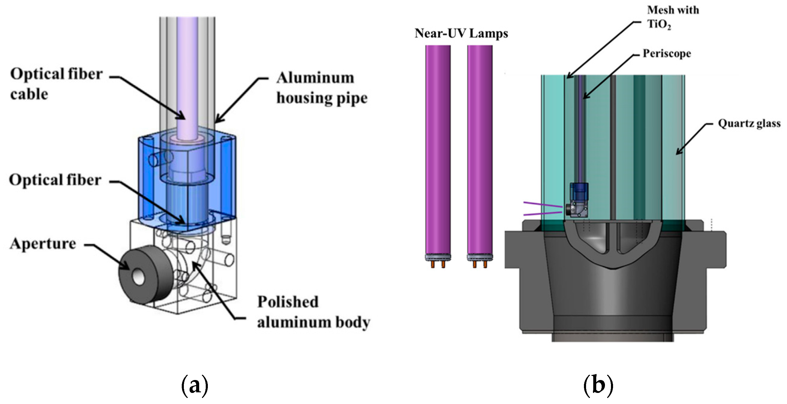
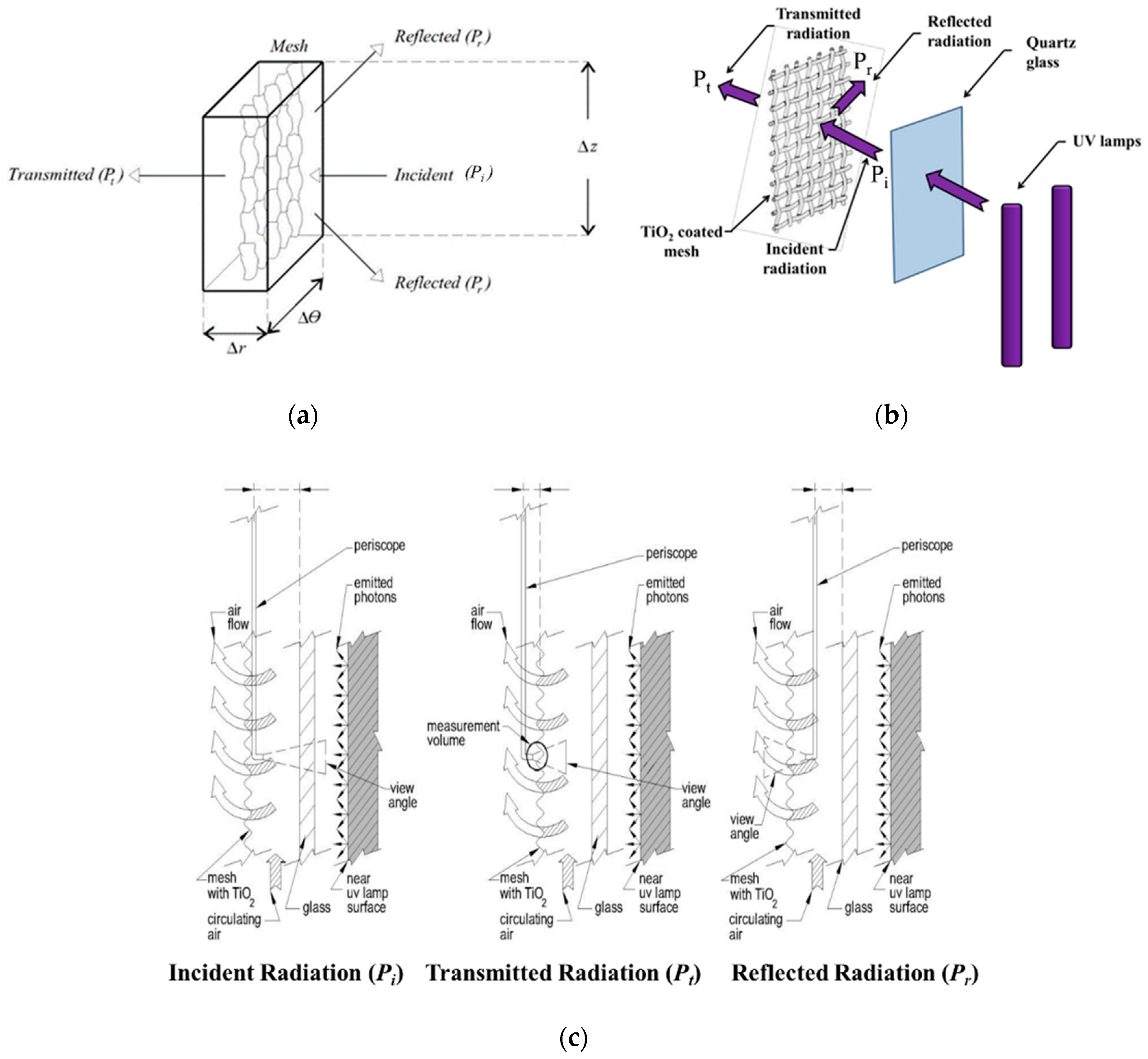
3.2. Position of Light Source

In photocatalytic reactor design and performance, one can see that photoreactors are conditioned by both the position and the location of the incident light sources. On this basis, one should consider (a) the single-lamp annular unit, and (b) the multi-lamp annular unit. These tubular reactor configurations, as described in Figure 3a,b, show an improved photon absorption, with transmitted photons being transported through inner or outer TiO2 deposition films [82]. These reactors provide symmetrical irradiation, facilitating the calculation of macroscopic irradiation energy balances [12,18,19,33,44].
Furthermore, a photoreactor type with an asymmetrical geometry also allows one to place the reactor light at different locations, as one can see in Figure 3c,d. However, this type of asymmetrical irradiation makes the evaluation of absorbed radiation much more complex [78,83,84,85].
Thus, while as described in Figure 3a–d photocatalytic performance shows the importance of photon flux irradiation patterns, it is important to state that the photocatalytic reactor efficiency also depends on how the photocatalysts are available on the irradiated surfaces.

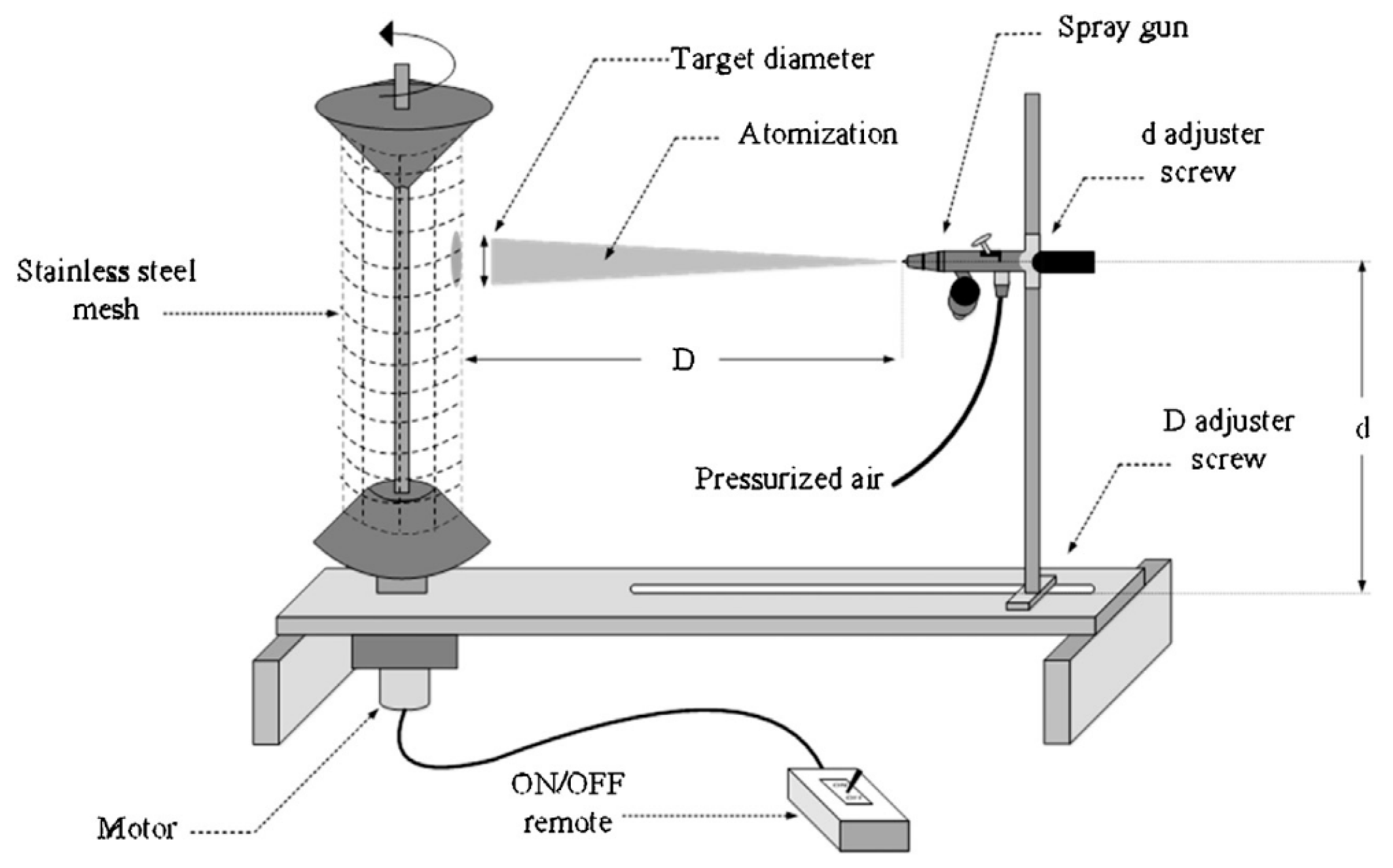
3.3. Photocatalysts Deposition Methods in Photo-Air Reactors

The study of photocatalyst deposition methods on support surfaces is important to obtain high-performing photochemical reactors. These methods facilitate the photocatalysts’ stability, durability, and surface bonding. Thus, a proper deposition method could allow one to create simple and cheap coatings on complex geometries [29]. Moreover, if properly selected and implemented, these methods could effectively help in determining the acceleration of the reaction rate by reducing the irradiation time for the photoconversion of organic pollutants. Table 3 reports different mesh types and common techniques utilized for the immobilization of TiO2.
Ibrahim and de Lasa (2002) studied a photocatalyst deposition method on a fibrous glass mesh. This fiberglass mesh required a pretreatment for the removal of the protective surface coating (meta-acrylate-chromic) involving several steps: (a) first, the mesh was soaked in a bath of nitric acid solution (70 wt.% HNO3) for 24 h; (b) then, it was rinsed with de-ionized water; (c) lastly, it was dried at 100 °C for 3 h, which helped with the removal of the coating precursor. After the completion of these steps, the pretreated mesh was brush-painted with a TiO2 suspension in order to coat the mesh fibers. Then, TiO2 impregnation was followed by 8 h of drying time to secure water removal [2].
Garcia-Hernandez et al. (2012) later suggested that an upgraded impregnation deposition method on a woven wire stainless steel (SS) mesh would be valuable. This method consisted of brush spreading a sonicated TiO2 slurry on a woven wire SS mesh, followed by drying [8]. Similarly, Haghighatmamaghani et al. (2019) coated TiO2 on a nickel filter surface using a pipetting method and then drying it at 80 °C for 12 h [56]. These DP25 coated meshes displayed high photocatalytic conversion of acetone [2,12], isopropanol [92,93], and hydrocarbon compounds (i.e., alkanes and BTX) [25,38,77,78] and other VOCs [14,15,20,23,94] photodegradation. Despite these advantages, new methods with better homogeneous coating control were claimed to be required.
A different approach to support TiO2 on an optical fiber was proposed initially by Ollis and Marinangeli (1980) [95] and further optimized by Peill and Hoffmann (1995) [23]. This method consisted of coating a stripped section of an optical fiber (3M Power-Core FT-1.1-UMT) with DP25 (TiO2). The coating was applied to the stripped section by inverting the bundle and pipetting a solution, followed by air-drying. Finally, the stripped section was heated to 300 °C while the unstripped section was heated to 110 °C for 1 h. This technique allowed light absorption efficiencies of 95% and the direct measurement of light fluxes for Quantum Yields calculations [23].
Verbruggen et al. (2011) studied an immobilization technique involving a one-step suspension coating on glass beads in a packed bed reactor. This method involved washing 2 mm glass beads with ethanol, and then drying them overnight at room temperature. Later, TiO2 powder was mixed in ethanol to be sonicated for 30 min. Following this, the glass beads were coated using different loadings of this mixture up to 1 wt.% TiO2. Then, they were air-dried for 15 min. Finally, the coated glass beads were oven-dried at 65 °C for 2 h. According to the authors, this method offers a convenient and versatile alternative compared to using photocatalytic pellets in the photodegradation of ethylene [96]. Furthermore, Hachem et al. (2001) coated glass plates (48 cm2) with 4 g/L of DP25 suspension. This was helpful to obtain thin deposits with an average of 10 microns optimal film thickness [97].
Lugo-Vega et al. (2016) developed an air-assisted spray coating unit as shown in Figure 4, with an automatized spinning method (TiO2-AAS-ASC). This method led to a high TiO2 dispersion over a 304 woven wire SS mesh (55.4 cm by 34.7 cm). The TiO2-AAS-ASC method consisted of spraying a rotating cylindrical woven wire stainless-steel mesh with a nozzle air gun. Using this device, the stainless-steel mesh was uniformly covered, with TiO2 particles being suspended in a water slurry. The set target distance of the gun to the mesh was 30 cm. The drum rotation was 12 rpm and the jet air pressure was 20 psia. The coated mesh was dried at room temperature for 24 h [12]. A similar spray coating technique was applied by Han et al. (2012) on a 10 cm by 5 cm by 0.3 cm nonwoven polyester filter mesh. The mesh was pre-washed in an ultrasonic washer with a 0.5% nonionic agent during 15 min. After this step, it was rinsed with Milli-Q water, followed by sonication for 15 min. Then, it was washed with acetone and dried in a N2 flow at room temperature. In addition, the mesh was spray-coated with a mixture of DP25 and Ludox AS-40 (binder agent) using a Navite F-75 G air gun with 65 psia of pressure at a 15 cm distance to obtain a uniform coating. Finally, the mesh was cured at 60 °C for 3 h to stabilize the coating [28,98].
Sirivallop et al. (2020) proposed a variation of the Lugo-Vega et al. method [12], using a cylinder of 304 stainless steel (SS) woven wire mesh with a total area of 700 cm2 and a 52% open area. This mesh (or substrate) was immersed in a diluted nitric acid solution for 1 min and wiped with acetone and ethanol. It was then dried at 100 °C for 3 h. Following this step, the mesh was coated with a brushing technique and a binder of poly (acrylic acid). Then, the mesh was dried at 80 °C for 2 h to achieve the photocatalyst particle immobilization [11].
A different dip-coating method was implemented by El-Kalliny et al. (2014). This technique used 304 SS woven wire mesh with a 214 cm2 of total area and a 52% open area. The uncoated SS mesh was first rinsed with deionized water and then dried with air. Following this step, it was cleaned with ethanol and methyl ethyl ketone, and dried further at 125 °C for 24 h. The TiO2 was immobilized on the mesh by horizontal dip-coating for 1 min (the number of TiO2 dips and loads varied depending on the film thickness applied). Then, the coating films were dried at 100 °C for 15 min. After this, they were calcined at 225 °C for 15 min to obtain an optimal adhesion of the catalyst film [88]. According to Herrmann et al. (1996), dip-coating can also be applied by immersing plates or meshes in a solution of titanium tetraisopropoxide (Ti(OCH(CH3)2)4). Either the meshes or the plates are removed from the solution at a constant rate. Then, they are dried in air for a few seconds until white cloudiness appears on the mesh. This occurs given the alcoholate hydrolysis on the adsorbed layer, which is induced by the ambient air humidity. This coating process was repeated until the desired TiO2 film thickness was reached. Finally, the support was calcined at 400 °C for 2 h. This last step combusted the alcohol precursor and desorbed the CO2 and/or any other carbon impurities present in the supporting material [99].
The deposition of TiO2 via a sol-gel method is another common immobilization method used to coat surfaces, including glass [100], quartz [101], metallic plates [102,103], ceramic foams [80] and cotton fabrics [104] with a film of colloidal TiO2. Harizanov and Harizanova (2000) developed a sol-gel process to stabilize xerogel colloidal TiO2 films on quartz. This coating method consisted of the polycondensation reaction and the hydrolysis of the suspension containing an organometallic precursor. This was followed by applying a stabilization and dip-coating technique. After this step, the photocatalyst supports were dried at 100 °C during 12 h, and calcined at 450 °C for 5 h, until an optimal TiO2 film thickness was obtained. One can observe that the resulting film consisted of nanocrystalline anatase with high optical quality [102]. Given that sol-gel methods were reported to be adequate for fused silica or mineral glasses, at 300 °C or above, Langlet et al. (2002) deposited TiO2 films on thermally sensitive (<150 °C) polymer supports. These supports consisted of polycarbonates and poly-methyl-methacrylates. A good photocatalytic decomposition of malic acid using anatase films with high crystallinity was obtained [105]. Furthermore, it was determined that sol–gel techniques can also help to prepare porous TiO2 pellets with high surface areas (≥150 m2/g), which can be placed in fixed-bed photocatalytic reactors [76,82,103]. For example, Yamazaki et al. (2004) used TiO2 pellets for the degradation of chlorinated ethylene in a tubular-packed photoreactor [106].
Harizanov et al. (1996) also considered chemical vapor deposition (CVD) on a glass support. This research group used W(CO6) as a precursor. Different gas atmospheres and temperatures (400 to 600 °C) were utilized in the preparation of CVD-W films. These films were claimed to have a high transmission of solar irradiation [107]. Rachel et al. (2002) introduced the fixation of TiO2 on solid supports (glass, cement, and red brick) and inorganic fibers, using different techniques such as sol-gel dip-coating and sputtering. According to these authors, the fixation of TiO2 on inorganic fibers provides good photocatalytic activity for the transformation of benzene into sulfonic acids [108].
Despite the progress achieved, nowadays different research groups are still attempting to achieve an optimal semiconductor deposition. This may lead to coatings with high photoactivity efficiencies of special potential value when using visible light for the inactivation of viruses. It is envisioned that these semiconductor coatings should be developed for industrial and commercial large-scale applications.

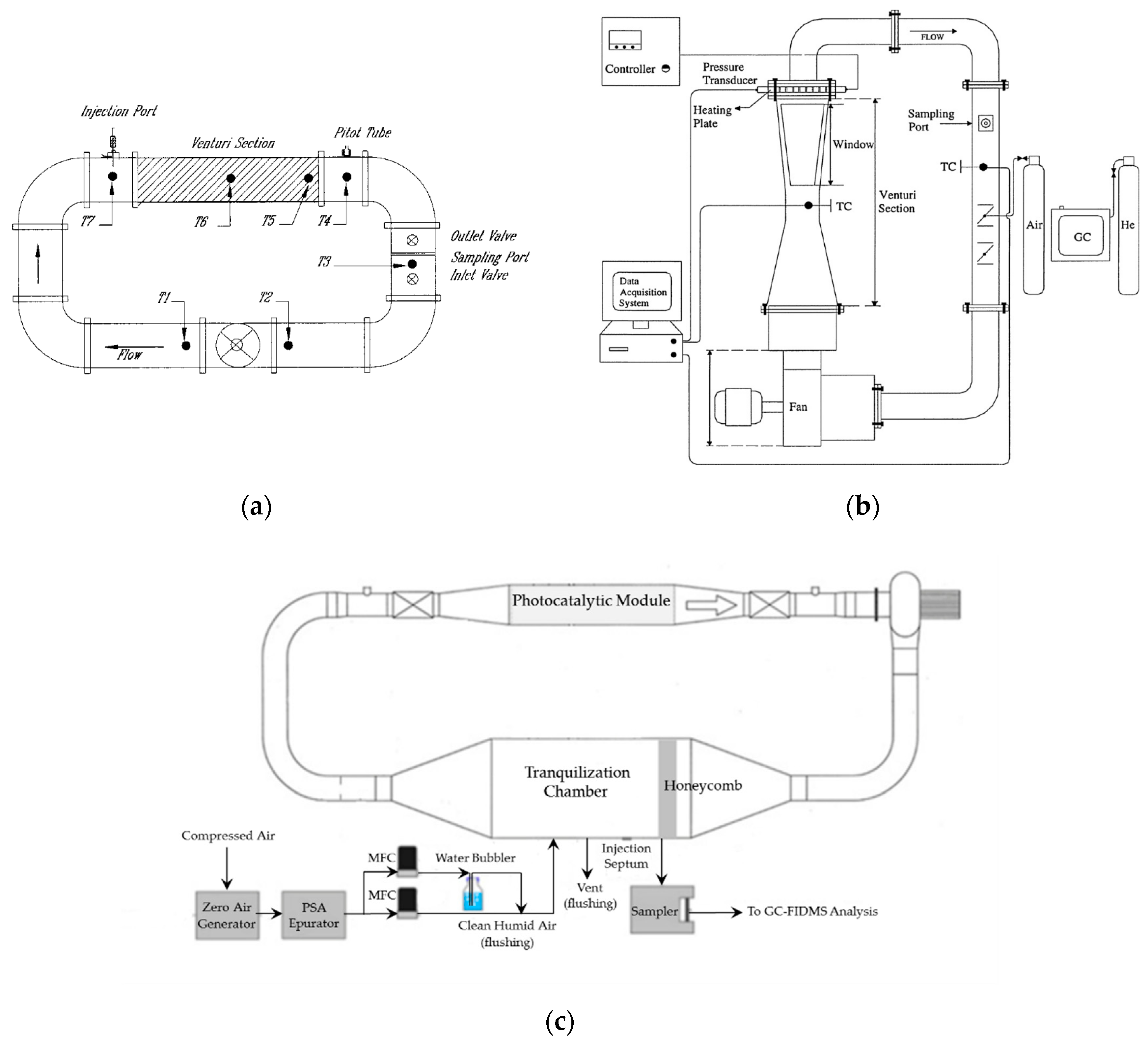
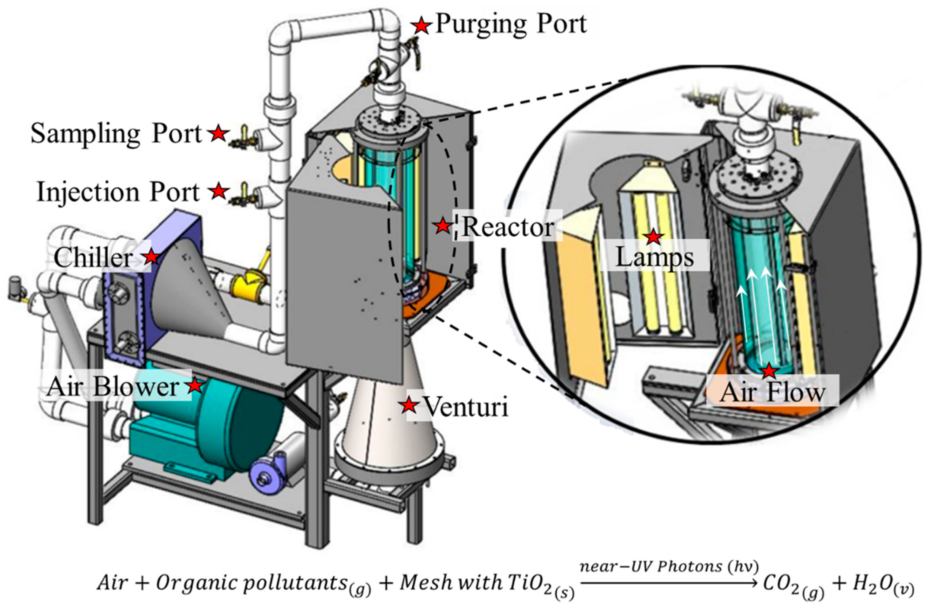
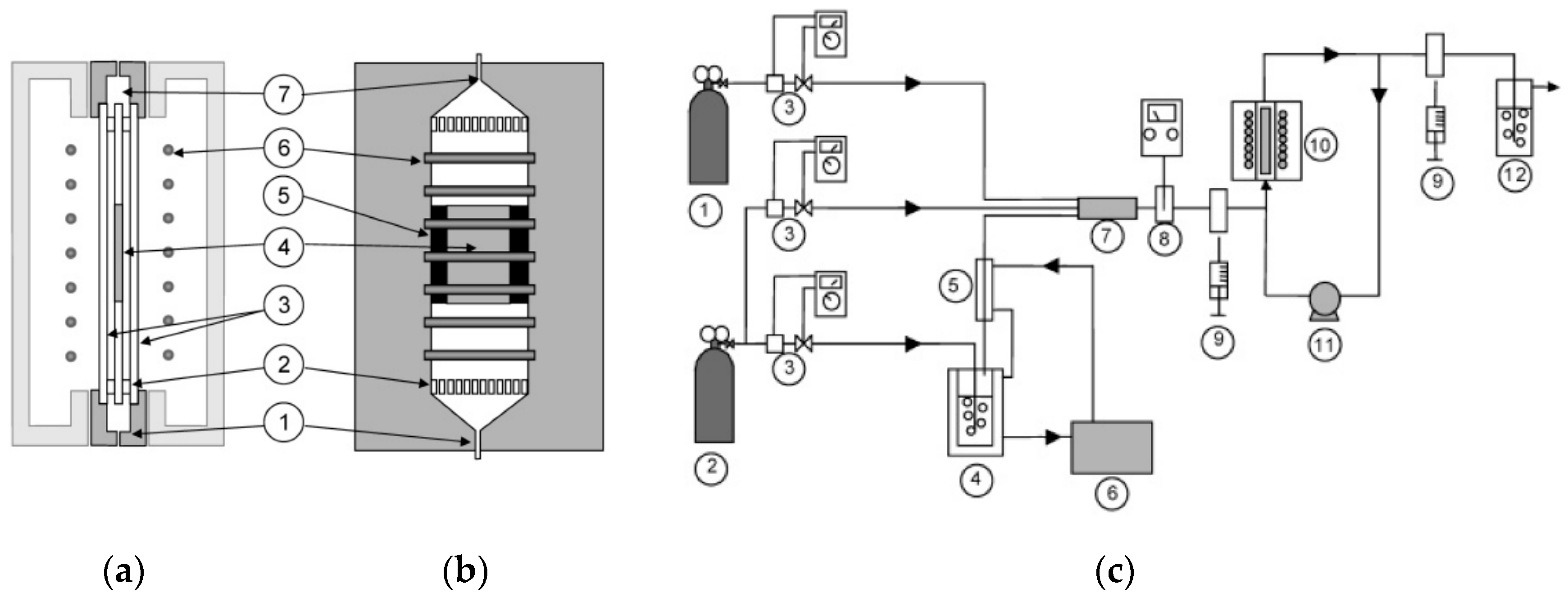
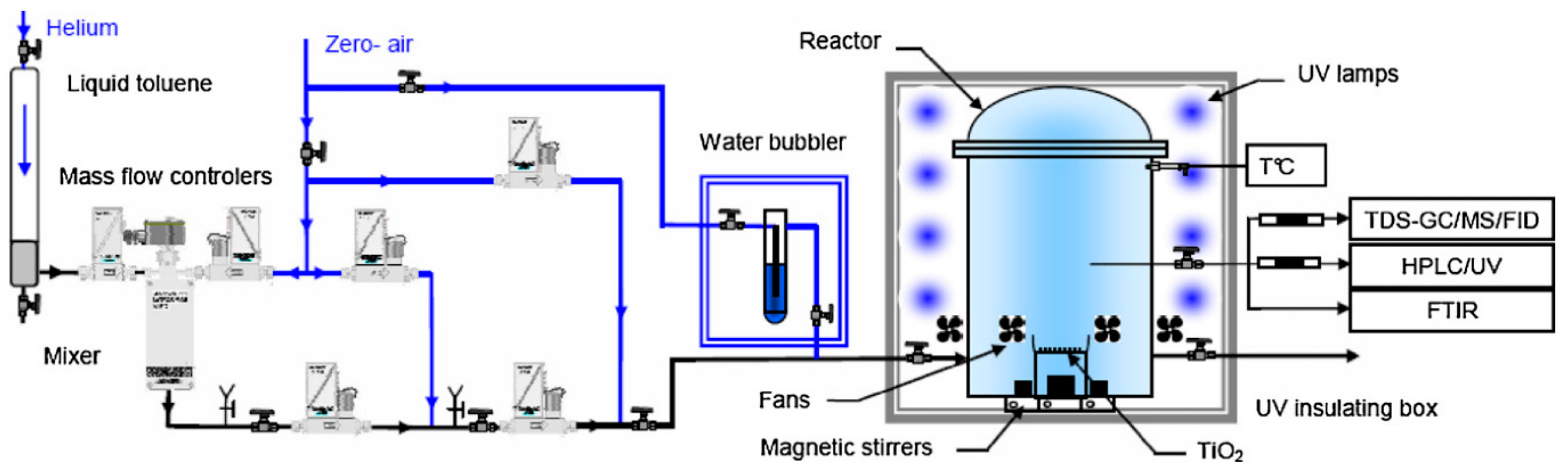
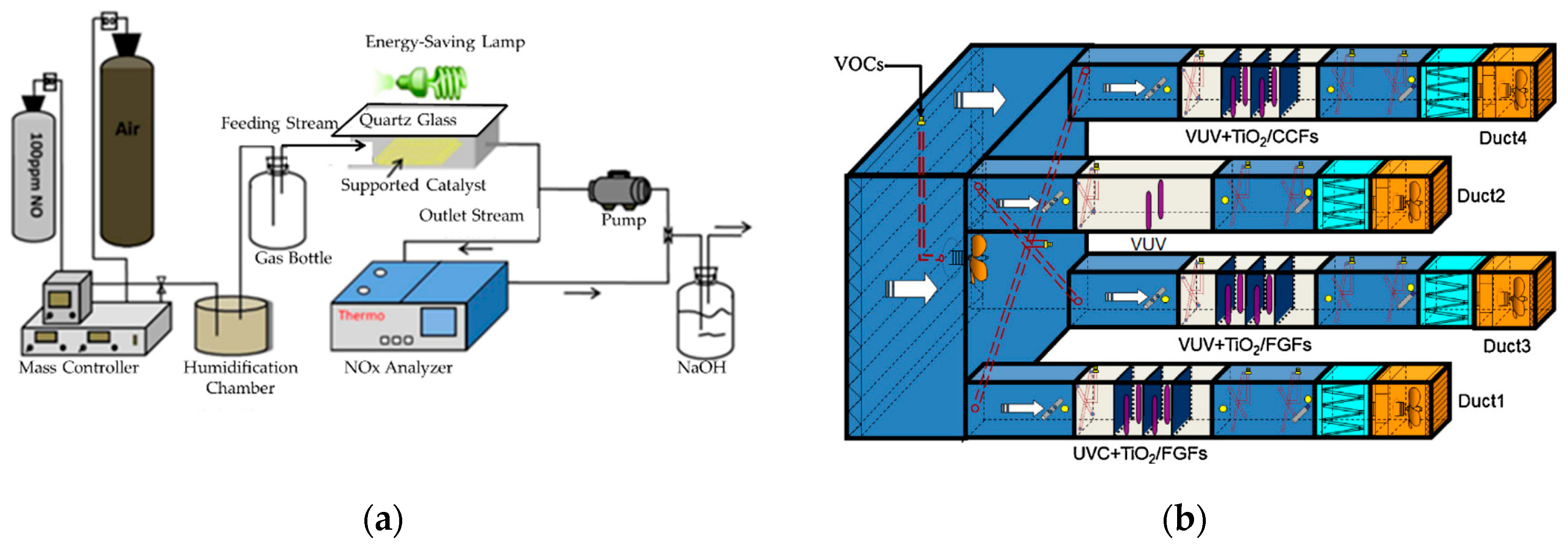
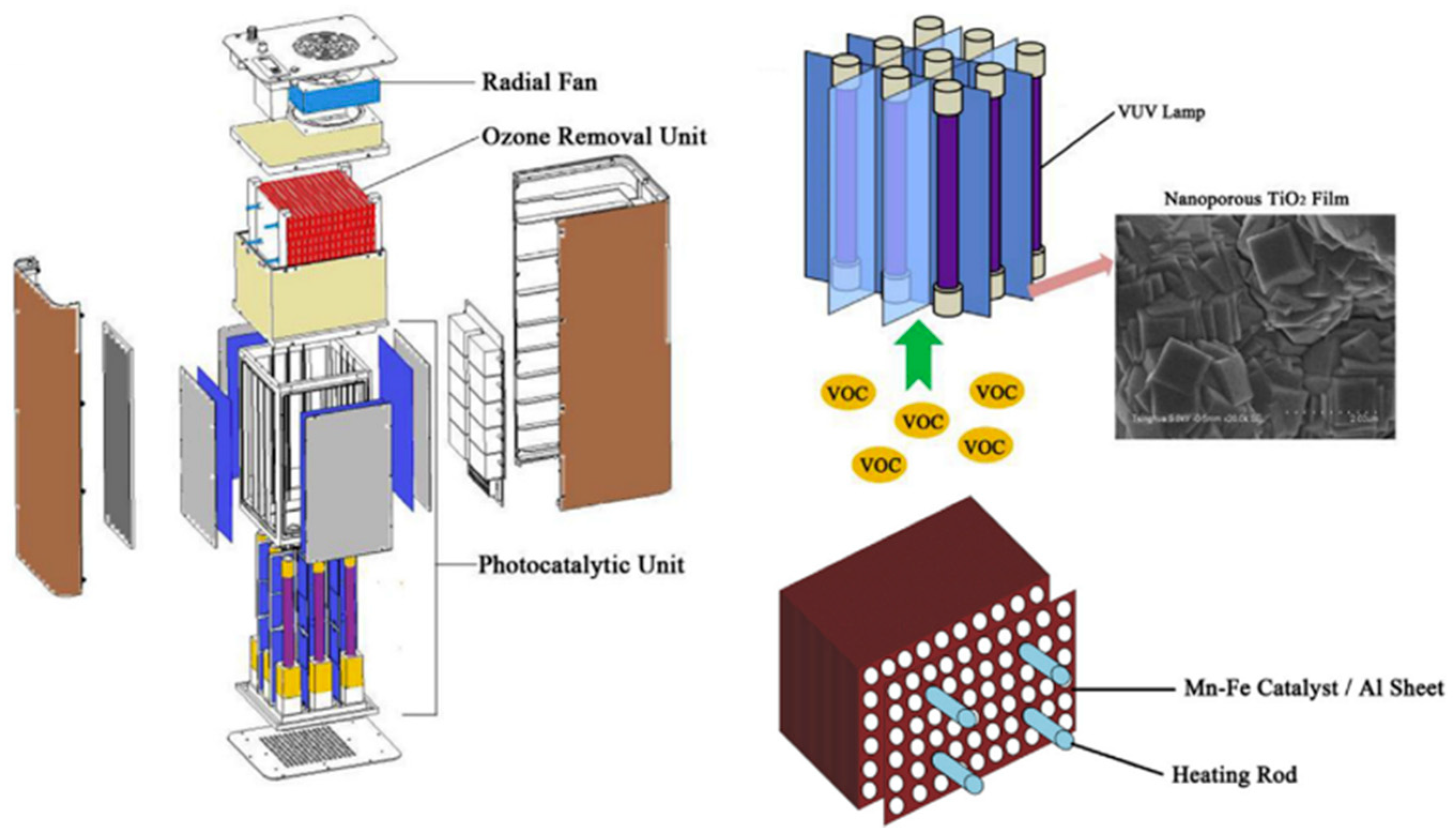
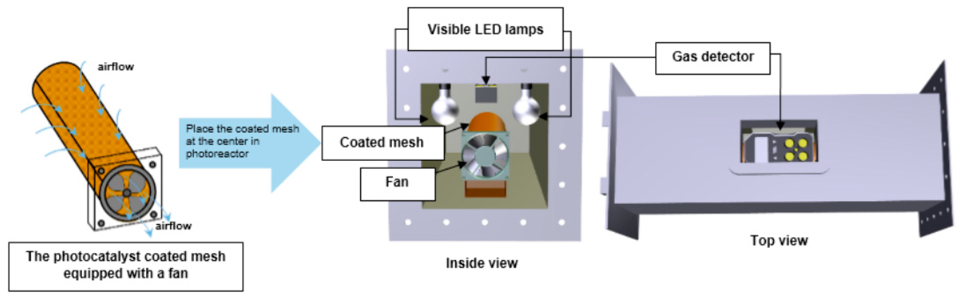
3.4. Experimental Photocatalytic Air Reactors for the Photodegradation of Organic Pollutants

There are two Photo-CREC-Air Reactors originally designed by Ibrahim et al. (1999 and 2002), which were proposed to investigate toluene and acetone degradation. These reactors were laboratory-scale closed-loop units of 65 L and 14.7 L, respectively. Both reactors also included (i) a Venturi section with either Degussa P25 or Hombikat UV-100 (TiO2) impregnated on a wire mesh basket, (ii) a heating plate, (iii) a fan, (iv) sampling ports, and (v) external lamps of 4 W (Pen-Ray®), symmetrically placed around the reactor and housed inside reflectors (see Figure 5a,b). During near-UV irradiation, each unit configuration reached: an ~38% conversion of toluene (13 μg/cm3) in 18 h and an ~99% photodegradation of acetone (40 μL solution) in 12 h [2,38].
A similar recirculation closed-loop system (refer to Figure 5c) was later designed by Héquet et al. (2017). This is a 420 L reactor with only 1.3% of the volume corresponding to the PCO section. This PCO section contains a honeycomb section, which provides a homogeneous airflow distribution. It also contains two 18 W UVA UV fluorescent tubes, placed inside the filter folds of the photocatalytic module. The filter folds are composed of a photocatalytic fibrous support (a mixture of cellulose, polyester and polyamide) which is coated with TiO2 in a SiO2 binder [84].
In further steps and based on preliminary experimentation and CFD available tools, the annular mesh-coated Venturi-reactor was upgraded [2,9,13,16,31]. The redesigned PCAR, as shown in Figure 6, is a 55.1 L scaled-up reactor with a closed-loop unit that provides an effective interaction between the fluid and the solid phase. In the PCAR, air recirculates using a GASP gas blower and is pumped into a SS Venturi section and then driven into the photoreaction section. Furthermore, this unit operates at close to isothermal conditions (~44 °C), with air being cooled to 5–10 °C, before reentering the blower.
The photoreaction section consists of eight (8) outer near-UV lamps (325 to 380 nm), each having a 15 W nominal power. Lamps are placed in pairs inside lamp-holders which are distributed equally around the circumference of an inner cylindrical quartz glass tube. A TiO2-coated mesh is supported by a bullet nose bottom, located inside the cylindrical quartz glass tube. This design provides in the reactor section both mesh irradiation and lengthwise gas crossflow from the annular region to the interior of the mesh. The PCAR also allows the determination of macroscopic irradiation energy balances permitting incident, transmitted and reflected light radiation measurements [12,14]. Lugo-Vega et al. (2016) reported that this photoreactor can completely mineralize acetone in air (45 μmol/L), after ~1.6 h of exposure to near-UV irradiation, with a 1 wt.% TiO2 photocatalyst loaded via the AAS-ASC method [12].
Imoberdorf et al. (2005) studied the tetrachloroethylene photocatalytic degradation in a photoreactor for air treatment, as shown in Figure 7a–c. These authors used a TiO2-coated “vertical” borosilicate glass plate, positioned in the same direction of the gas flow. Figure 7a,b show the unit components: (1) a gas inlet, (2) a flow homogenizer, (3) acrylic windows, (4) a photocatalytic plate section, (5) an opaque film, (6) 14 near-UV lamps (black light types) and (7) a gas outlet. Figure 7c describes the components of the process flow diagram: (1) the combined tetrachloroethylene and airflows, (2) the airflow, (3) the mass flowmeters, (4) the air humidifier, (5) the heat exchanger, (6) the thermostatic bath, (7) the mixer, (8) the thermo-hygrometer, (9) the sampling device, (10) the photoreactor, (11) the recycle pump, and (12) the gas scrubber. This reactor with a TiO2-coated plate was operated under a kinetic control regime [83].
Debono et al. (2011) developed a 120 L laboratory batch reactor for the photocatalytic oxidation of VOCs. The device included (1) a VOC generator, (2) a reaction section with 100 mg of DP25 (TiO2) dispersed in the lower chamber section, and (3) analytical units for VOC detection and quantification. This reactor was operated at room temperature, with controlled humidity and with nine (9) PL-L-40 Philips near-UV lamps of 365 nm each (see Figure 8). A homogeneous photon flux of 10 ± 1 mW/cm2 was used. This unit was able to provide a complete photodegradation of toluene following 12 h of irradiation [77,78].
Dong et al. (2014) customized an experimental 4.5 L continuous flow photocatalytic reactor, with a “horizontal” TiO2-coated ceramic foam, placed in the same direction as the gas flow. This reactor was specifically designed for operation at ambient temperature under controlled relative humidity and using two (2) domestic energy-saving lamps (refer Figure 9a). Efficiency was demonstrated by eliminating 600 ppb of NO in air at room temperature and close to atmospheric pressure, achieving a 77% NO removal in 30 min as NO2 and H2O [80].
Furthermore, Zhong et al. (2013) used a different open-loop photocatalytic reactor design, made of four “parallel” aluminum ducts, with commercial filters coated with TiO2, situated transversally to the direction of the airflow. This research group studied the oxidation of a variety of VOCs (refer to Figure 9b) by using (i) a vacuum ultraviolet (VUV) lamp and germicidal (UVC) irradiation amounting to 18.4 W per lamp, (ii) a gas mixer feeder, (iii) two commercially available filters for TiO2 coating, with these being fabricated of fiberglass and carbon cloth fiber, (iv) airflow rates of 255 m3/h, generated by a radial fan (mounted at the end of each duct) with a speed regulator, and (v) controlled humidity and temperature. This study reported a close to 40% degradation of VOCs for 0.25 to 2 ppm inlet concentrations during 10 h of operation [79,109].
More recently, an experimental photocatalytic air reactor with an 11 L volume (refer to Figure 10) was developed by Xu et al. (2018). The air gas stream was contacted by several nanoporous TiO2 coated “vertical” plates, placed in the same direction of the gas flow. This photocatalytic unit was equipped with (a) nine (9) low-pressure mercury VUV lamps of 10 W, (b) an ozone removal unit with heating rods and temperature sensors (0–100 °C), and (c) a fan controlling the airflow (~96,000 L/h). This system exhibited good stability and efficiency, removing about 48% of the formaldehyde and 79% of the total VOCs after 90 min of operation time [85].
Very recently, a laboratory reactor configuration for air pollution control was reported by Sirivallop et al. (2020). This bench-scale reactor (54 L) operates at room temperature and consists of an “annular” immobilized cylindrical coated-stainless steel wire mesh (coated with an optimal in-situ solvothermal photocatalyst), two visible LED lamps (of 16 W of nominal power), and a fan to circulate ammonia inside a reactor box (refer Figure 11). This reactor configuration achieved an ~38% photodegradation of NH3 (30% aqueous solution) into N2 and H2O during using 5% N/Ag co-doped TiO2 photocatalyst under 6 h of LED irradiation [11].
Thus, on this basis, one can conclude that experimental studies which were reported using photocatalytic air purification units, based on diverse possible designs, are still being tested and are under development. In our view, it is worth mentioning that the most advanced photoreactors for this purpose, such as is the case of the Photo-CREC-Air Reactor (PCAR), offer a high degree of uniformly immobilized and irradiated TiO2, as well as controlled photocatalyst contact with the cross-flows of air. These units offer, in principle, a novel and unique opportunity to manufacture scaled commercial photocatalytic reactors that can efficiently remove indoor pollutants in excess of ~99%.

4. Photodegradation Modeling Studies for Air Treatment Using TiO2-Based Photocatalysts

In order to progress with photocatalytic oxidation (PCO), there are two issues of major importance: (1) the clarification of photoconversion kinetics and (2) the development of CFD (Computational Fluid Dynamic) modeling. In particular, nowadays, CFD modeling has progressed considerably, as it is able to provide reliable and accurate fluid flow calculations [110].

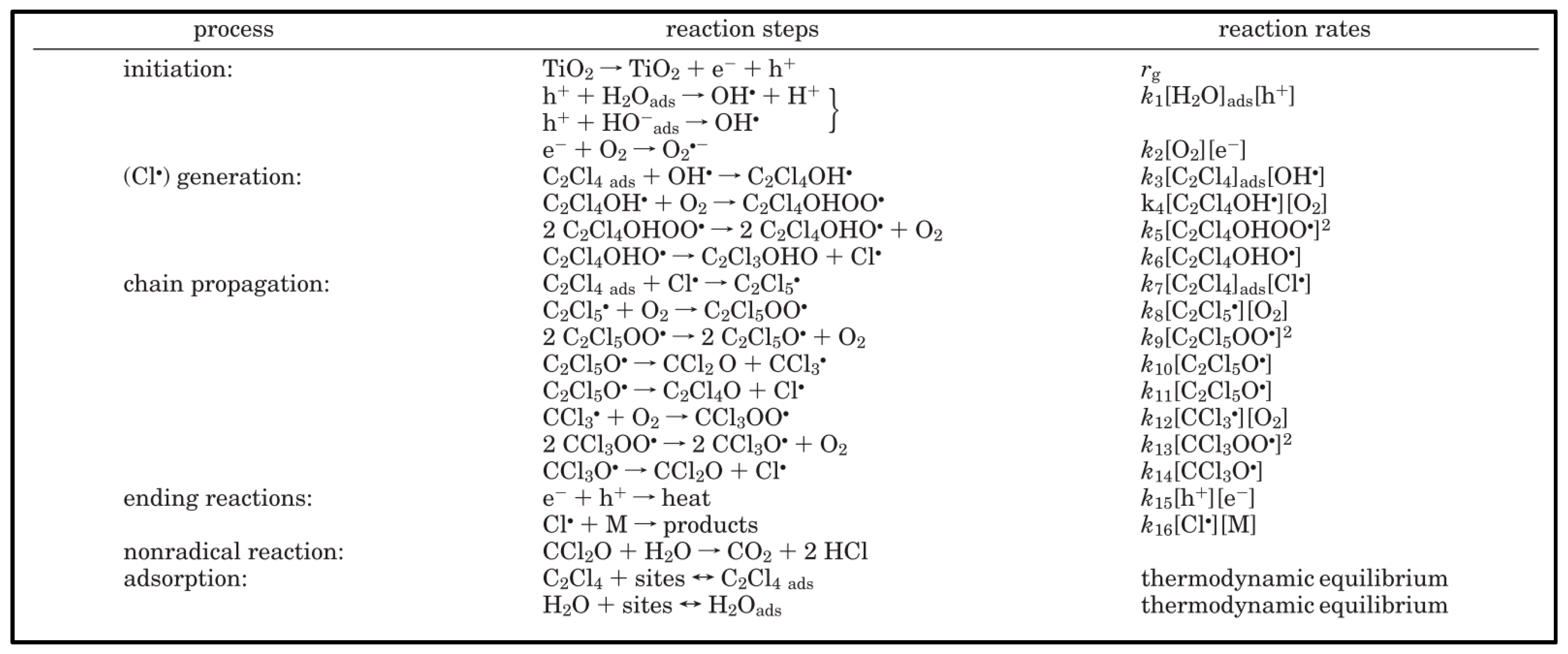
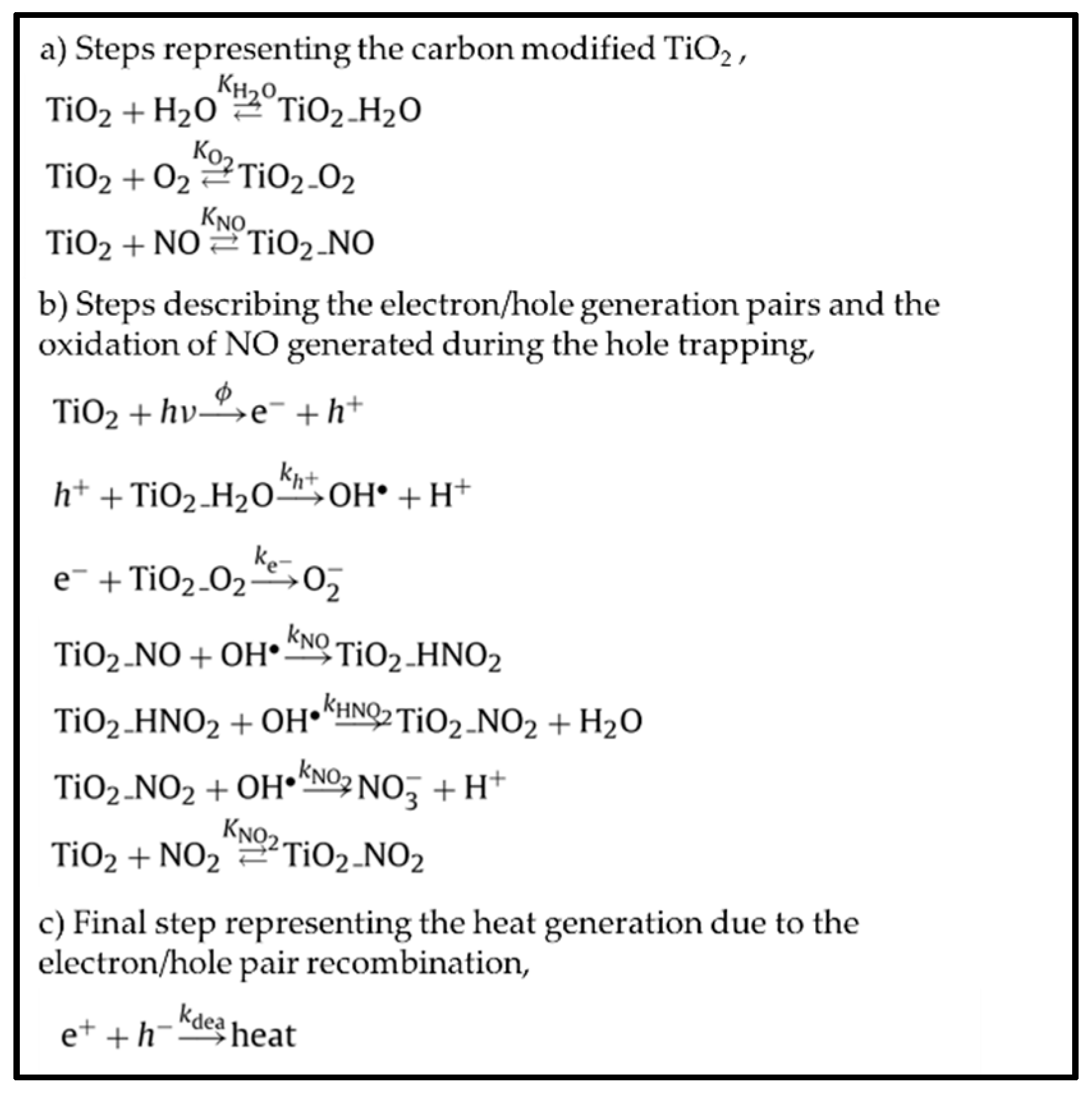
4.1. Reaction Mechanism Development

During the last two decades, the significant advancement of photocatalytic kinetic models has been reported. These kinetic models are based on bimolecular photocatalytic oxidation reactions occurring between the adsorbed species and oxygen [3]. Salaices et al. (2004) proposed a reaction mechanism involving a parallel-series reaction network (refer to Figure 12), for phenol photoconversion in aqueous media. This model was supported by experimental data (arrowed-lines) and sound assumptions (arrowed-dashed lines) [111]. Furthermore, this model has been used as a groundwork for further kinetic studies in the photoconversion of organic pollutants in water [112,113,114], air [8,31,33], and for hydrogen production [34,115] at the CREC-UWO laboratories.
In particular, it can be mentioned that the CREC-UWO group has led the development of the parallel-series reaction network for air treatment, describing photodegradation of acetone, acetaldehyde, and isopropanol into CO2 and H2O when using TiO2 [8,31,33]. This practical and effective reaction network, based on measurable chemical species, was validated accounting for the variable absorbed photon density at various photocatalyst irradiated site locations. This intrinsic photoreactor characteristic led to both h+ site and OH radical group variability. As a result, the photocatalytic reactor yielded photocatalytic reaction steps which took place with different oxidation extents. This scenario gave: (a) CO2, from the very beginning of the irradiation period, and (b) other intermediate species, requiring a lower number of OH radicals than those for the complete mineralization of the model pollutant.
On the other hand, Imoberdorf et al. (2005), proposed a more complex sequence of elementary reaction steps. This reaction mechanism involved radical species and was considered adequate for the degradation of tetrachloroethylene [84]. The series of postulated reaction steps are summarized in Figure 13.
Yu et al. (2010) also introduced a kinetic model for the photocatalytic oxidation of nitric oxide (NO) [116]. This process is described in Figure 14. This mechanism involves both measurable and non-measurable intermediate radical species.
Thus, while the present review reports relevant photocatalytic mechanisms, one can observe that researchers are still debating on how to proceed further to obtain kinetics for indoor air purification. It is our view that the “series-parallel” model, first introduced by CREC-UWO researchers [111], provides an excellent approach for describing measurable species concentration changes, as well as a workable method to establish the consumption of OH radicals at every step of the photocatalytic conversion, and using stoichiometric equations. It is also anticipated this “series-parallel” kinetic model based on observable oxidized species can help to improve photocatalytic reactor design. This is due to the kinetic model’s simplicity and accuracy.

4.2. Adsorption and Kinetic Modeling Development

There are three important kinetic parameters to assess photocatalytic performance: (i) photoreaction rates, (ii) adsorption constants, and (iii) intrinsic kinetic constants. These parameters are influenced by (a) humidity, (b) temperature, (c) wavelength, (d) radiation intensity, (e) gas velocity, (f) residence time, (g) photocatalyst loading, (h) oxygen and (i) organic pollutant concentration. The variation of any of these parameters can help us to improve the scale-up of photocatalytic processes [3].
Regarding adsorption, a Langmuir adsorption isotherm can be considered to be a suitable expression for the adsorbed species on the TiO2 at equilibrium [10,34,117,118]. This expression can be represented as follows:
θ A = Q e q , a d s Q e q , m a x = K e q , i A C e q , i ( 1 + K e q , i A C e q , i )
where θ A stands for the dimensionless surface species concentration, where Q e q , a d s and Q e q , m a x in (mol/gcat) represent the existing and maximum equilibrium adsorption surface concentrations, respectively; where C e q , i (μmol/m3 or ppm) denotes the equilibrium of species “i” in the gas phase concentration, or in the model pollutant concentration; and where K e q , i A (m3/μmol or ppm−1) represents the adsorption equilibrium constant. In this respect, only a few studies estimate adsorption constants using independent equilibrium experiments. Adsorption parameters can be assessed using “dark” conditions (without irradiation). This allows for independently calculated adsorption parameters, minimizing in this respect the intrinsic kinetic parameters cross-correlation. Therefore, it is apparent that it is adequate to independently calculate Langmuir adsorption parameters, reducing cross-correlation and, therefore, parameter calculation uncertainty [119,120,121].
However, in humid air conditions, Maudhuit et al. (2011) established that the classical adsorption model as in Equation (1) cannot be applied. Consequently, a new approximation designated a “Langmuir-multi” model was considered. This model was built and fitted to the experimental data for the adsorption of toluene and acetone. According to their hypotheses, the first part of the curve of the Langmuir equation was kept as Equation (1) for 0 C e q , i 3   mmol / m 3 For higher C e q , i 3   mmol / m 3 however, the Langmuir-Freundlich Equation (2) was considered for different possible mechanisms accounting [122] for:
Q e q , a d s = Q e q , m a x 1 K e q , i A 1 C e q , i ( 1 + K e q , i A 1 C e q , i ) + Q e q , m a x 2 K e q , i A 2 ( C e q , i C e q , I n f ) n 1 + K e q , i A 2 ( C e q , i C e q , I n f ) n
where Q e q , a d s , Q e q , m a x 1 and Q e q , m a x 2 in (mmol/gcat), represent the existing and maximum equilibrium adsorption surface concentrations; where (−1) and (−2) are the Langmuir and Freundlich adsorption isotherms, respectively; where C e q , i (mmol/m3) denotes the equilibrium of species “i” in the gas phase concentration or model pollutant concentration; where K e q , i A 1 and K e q , i A 2 (m3/mmol) represent the adsorption equilibrium constants for the Langmuir and Freundlich adsorption equations, respectively; where C e q , I n f (mmol/m3) stands for the inflection point observed in the adsorption isotherm; and finally, where n is the number of adsorption layers.
Regarding reaction rate models, it has been established that organic pollutants are adsorbed at equilibrium on TiO2 surfaces [71,123,124,125,126,127,128,129]. Thus, one has to consider mathematical models, such as the Langmuir-Hinshelwood (LH) kinetics [3,10,14,123,125,126,127,128,130,131,132]. Thus, the general expression of the Langmuir-Hinshelwood equation for batch reactors, with different model pollutants photoconverted in air, is given by:
V d C i d t = r i A
r i = V A d C i d t = K e q , i A k i C e q , i ( 1 + K e q , i A C e q , i ) = C e q , i ( θ 1 , i + θ 2 , i C e q , i )
where V (m3) represents the total gas contained in the PCAR; where k i (μmol/min m3) represents the equilibrium kinetic constant of species “i”; where r i (μmol/min × m2) is the rate of photoconversion of the model pollutant “i”, and where A (m2) is the uniformly irradiated mesh area holding an optimum loading of TiO2 particles. Furthermore, Equation (4) can also be represented in terms of θ n , i parameters, where θ 1 , i = 1 / K e q , i A k i = (min) and θ 2 , i = 1 / k i = (min m3/μmol).
Thus, once the irradiation is initiated, the photocatalytic oxidation of species “i” leads to the formation of intermediate species, that can also be adsorbed on the TiO2 surface. Then, Equation (4) can be modified to include the formation of one or more kinetically important intermediate species ( K e q , j A C e q , j ) [8,133,134,135], as follows:
r i = ( V A ) K e q , i A k i C e q , i ( 1 + K e q , i A C e q , i + K e q , j A C e q , j )
Using this approach, Ibrahim and de Lasa (2003) established a kinetic model similar to the one reported via Equation (5). This was the basis of a Photo-CREC-Air Reactor model for VOCs’ photoconversion. In Equation (5), adsorption and intrinsic reaction parameters can also be established using a least-square non-linear regression analysis with the related statistical indicators [10].
Vorontsov et al. (2000) reported a different approximation for the complete mineralization of acetone, using platinized titanium dioxide (Pt/TiO2) as a photocatalyst. The authors employed a variation of an LH equation by considering two types of adsorption sites (surface hydroxyl groups and Ti4+ ions) as shown in Equation (6) [136]:
r i = K e q , 1 A k 1 C e q , 1 1 + K e q , 1 A C e q , 1 + K e q , 2 A k 2 C e q , 2 1 + K e q , 2 A C e q , 2
Intrinsic kinetic and adsorption constants have been studied in the technical literature for the photodegradation of common VOCs including acetone, acetaldehyde, toluene, and isopropanol. These studies have also been performed both in bench-scale and scale-up reactors (i.e., Photo-CREC-Air Reactor) and represent a step forward in the implementation of PCO processes. Table 4 reports intrinsic kinetic constants and adsorption parameters, reported by different authors using the previously listed set of Equations from (1) to (6).
It is important to state that while there has been progress in terms of kinetics for photocatalytic reactors, this is still a critical area that deserves further attention. This area involves the successful scale-up of these units, as well as photoreactor unit design performance based on quantum efficiencies.

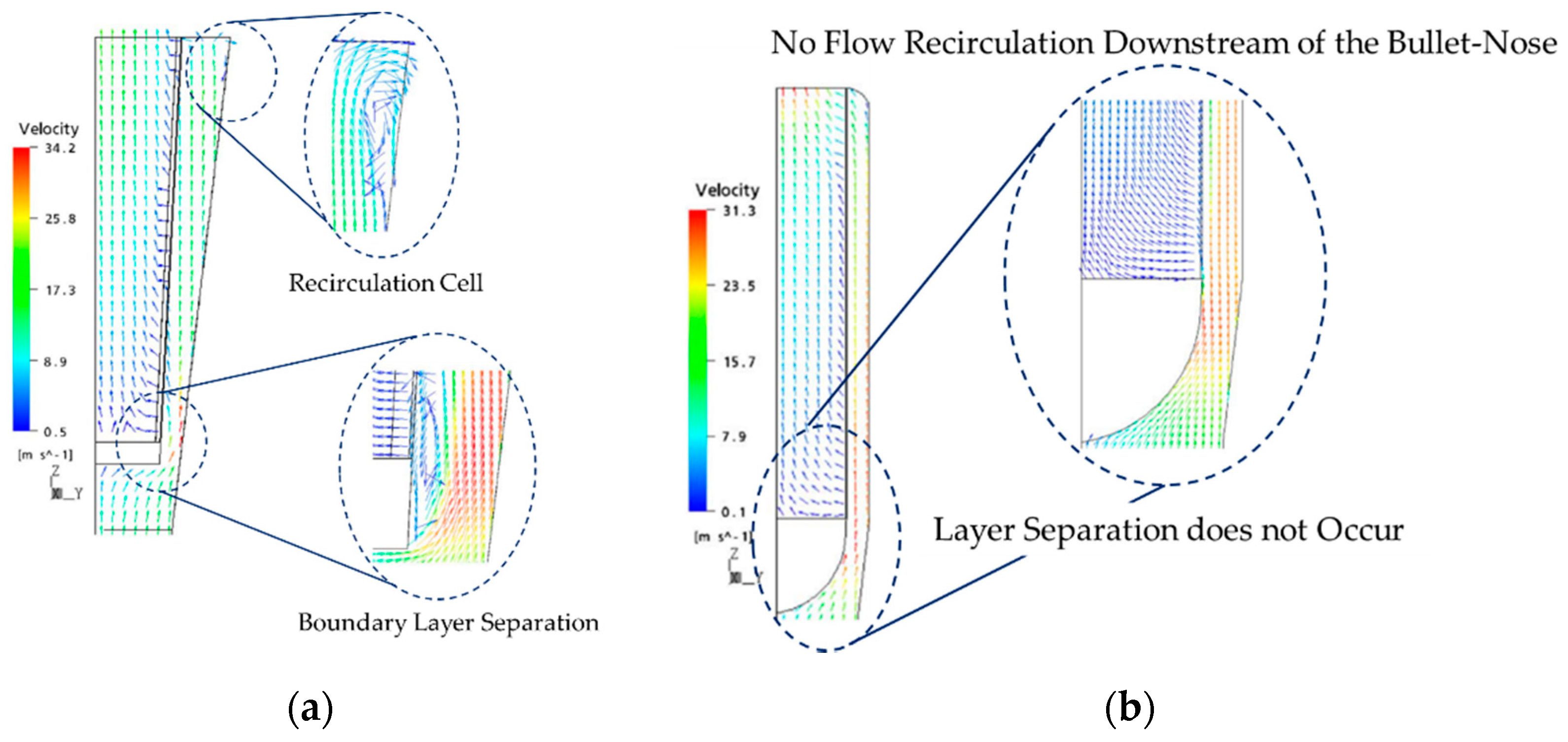
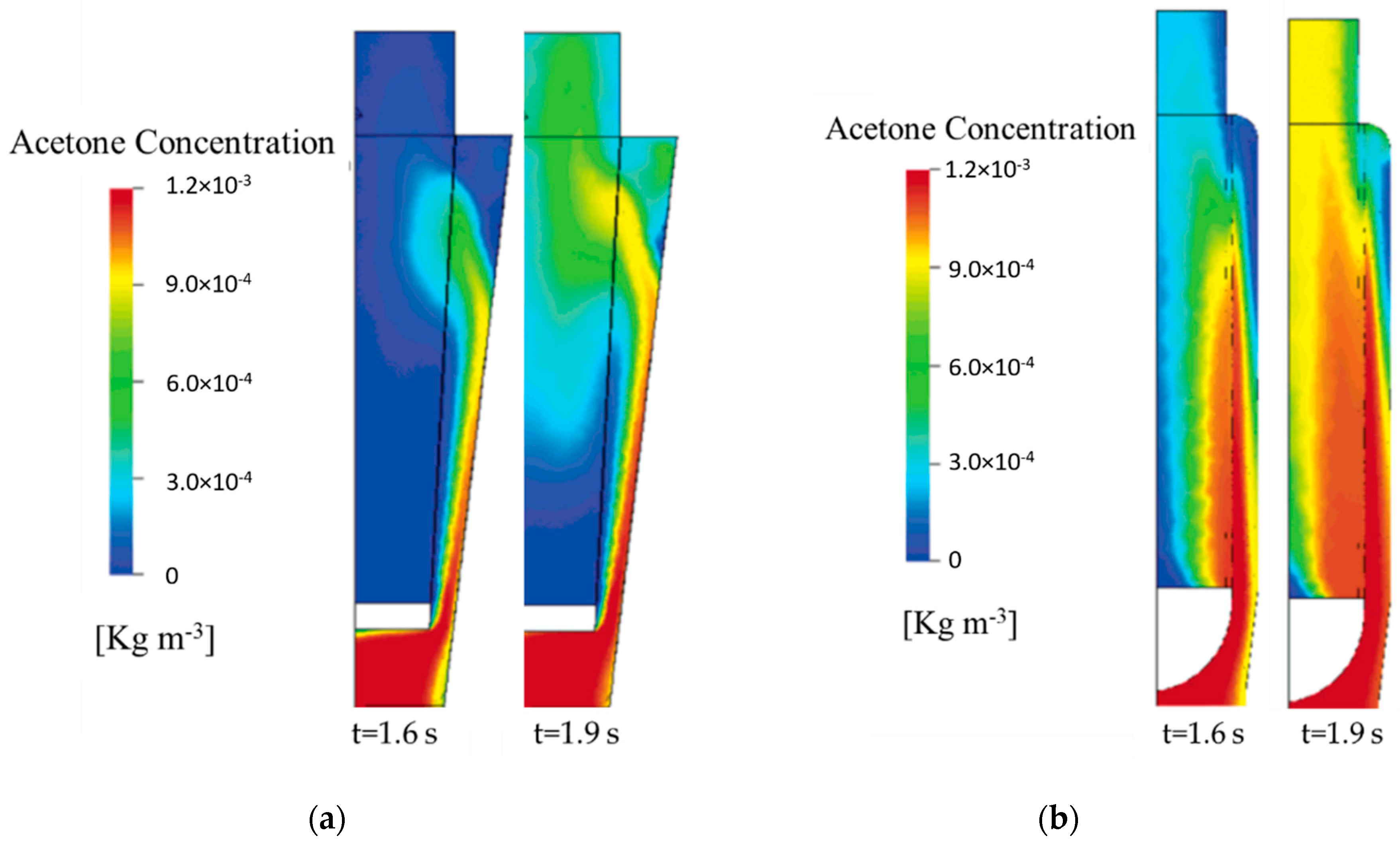
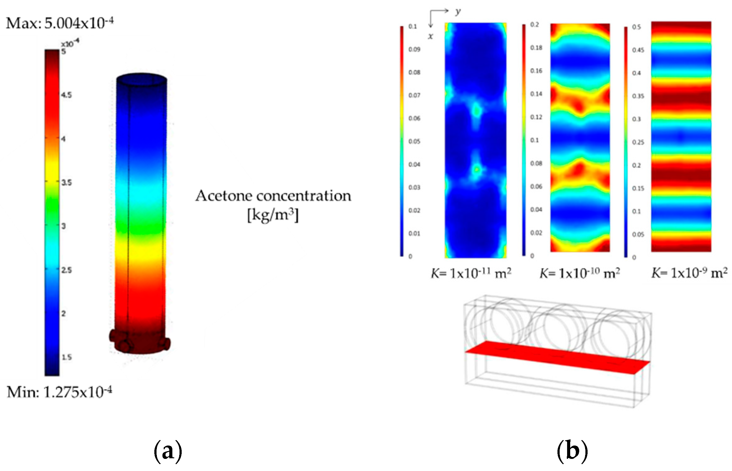
4.3. Computation Fluid Dynamic (CFD) Development

Computational fluid dynamics is an emerging and efficient tool that allows a better understanding of fluid flow patterns. It is critical to address the analysis, the development and the optimal design of photocatalytic reactors for air or water treatment processes [37,82,137]. Performing hydrodynamic simulations is the first step in the modeling of photoreactors. The Navier-Stokes equations are adequate for calculating the hydrodynamics of single-phase reactor systems. Nevertheless, for multiphase flows, there are two general methodologies: (i) the Eulerian-Eulerian (E-E) model, and (ii) the Eulerian-Lagrangian (E-L) model. In general, E-E models are preferred to solve multiphase flows compared to the E-L models, because of their rigorous computational approach [36].
Romero et al. (2006) reported the application of CFD modeling to the design of a pilot-scale photocatalytic air treatment reactor. This study, considered in the context of Photo-CREC-Air Reactor unit, originally developed by Ibrahim and de Lasa (2002) [2], was valuable to identify potential design issues and then to envisage a modified design with improved irradiation and flow field parameters. The CFD analysis was performed using CFX-5.7.1 (Ansys, Inc., Canonsburg, PA, USA), which is commercial software that uses the finite volume method to solve the discrete forms of transport equations. In this respect, the numerical solution of the Photo-CREC-Air Reactor (PCAR) was developed by using the steady-state continuity and the Reynolds averaged Navier-Stokes equations [13].
CFD simulations, as reported in Figure 15a, allowed our team to establish that in the first PCAR-1 unit there was: (a) a boundary layer separation, downstream from the basket base, caused by the basket sharp edge, favoring a dead volume formation; and (b) poor photocatalyst utilization due to the gas recirculation observed. On the other hand, Figure 15b showed the significant improvements achieved in the PCAR-2 by having (a) uniform near-UV irradiation on the photocatalyst, (b) a more regular flow field and velocities in the annular region, and (c) more uniform gas mass flows and fluid contact times [13].
Later, Romero et al. (2007) also examined the reactor decontamination performance (see Figure 16) using CFX-10 in a continuous mode [9]. This was done by incorporating the acetone kinetic model proposed by Ibrahim and de Lasa (2004) [31]. The CFD governing equations used in this study were
(a)
Reynolds-averaged mass,
ρ t + ( ρ U ) = 0
(b)
Momentum,
ρ U t + { ρ U U } = { τ + τ t } + S M
(c)
Acetone transport,
C A c t + { U C A c } = ( ρ ( D + D t ) ( C A c ρ ) ) + S C
where ρ is the fluid density (kg/m3); where stands for the gradient vector of x, y and z coordinates; where t is time (s); where U stands for fluid velocity vector (m/s); where is the tensor product; where τ and τ t represent the stress tensor and the Reynolds stress tensor (N/m2), respectively; where S M is the momentum source/sink term (kg/m2 s2); where C A c stands for the acetone concentration (kg/m3); where D is the diffusivity of acetone in air (m2/s) and was estimated with the method developed by Fuller et al. [138]; where D t represents the eddy diffusivity (m2/s); and where S C is the acetone source/sink term (kg/m3 s).
The Reynolds stresses, represented with the τ t term in Equation (8), were calculated with the k-w Shear Stress Transport (SST) turbulence model [9]. Furthermore, local density variations were calculated using the ideal gas law and assuming pressure domain ambient conditions to be 1 atm. Furthermore, one should note that the energy equation was not included in the model, given that isothermal operation was assumed, setting the domain temperature to ~25 °C.
The CFD simulation of the PCAR reported in Figure 16 compares two different single-pass photoreactor designs showing that (a) the PCAR-1 displays poor volumetric flow and low acetone conversion; and (b) the PCAR-2 shows a higher acetone photoconversion of 7.8%, which is attributed to a higher near-UV irradiation flux, a larger surface area available for the reaction and improved volumetric flow [9]. These results also show the limitations of the continuous photocatalytic single-pass reactors operation for VOCs’ removal.
Vincent et al. (2011) also implemented a CFD model for the photocatalytic degradation of acetone in an annular reactor (refer to Figure 17a). The CFD modeling provided a good description of the plug flow dispersion in the reactor, especially when the Navier-Stokes, the Brinkman, and the convection-diffusion equations were used [35]. Similarly, Degrave et al. (2015) employed the governing stationary equations given by (a) the Navier-Stokes model for the fluid domain and (b) the Darcy-Brinkman model for the porous media. These authors proposed a numerical model at the optical fiber scale to perform numerical simulations in geometrical domains. It consisted of a representative volume element (RVE) of the photocatalytic surface with periodic boundary conditions. For instance, this method allowed the authors to determine the permeability of the fabric (K), in which the higher the K, the higher the slip velocity (10−10 m2 < K < 10−9 m2). Figure 17b reports the spatial field of the airflow at the interface between the porous fabric and the free flow region [139].
On this basis, it is apparent that modeling studies of photocatalytic reactors using CFD must be developed. This will help to improve reactor design and operation, as well as to reduce the manufacturing cost of medium and large-scale systems.

5. Energy Efficiency Studies for Air Treatment Photoreactors

Energy efficiencies in photocatalytic reactors are of critical importance because they establish the performance of a specific design. Nevertheless, their evaluation is still a challenge given: (i) the photocatalyst absorbed irradiation, (ii) the reaction networks (or mechanism), (iii) the kinetic constants ( k i ) and (iv) the adsorption constants   ( K e q , i A ) .
In this review, we summarize some of the most relevant efficiency parameters in photocatalytic processes. We consider both the Quantum Yields (QY or φ ) and the Photocatalytic Thermodynamic Efficiency Factors (PTEFs). These parameters help us to calculate the efficiencies of air treatment photoreactors. Table 5 presents data comparisons between quantum efficiencies and PTEFs for different VOCs when a TiO2-based photocatalysts is employed.

5.1. Quantum Yield (QY or φ )

The Quantum Yield is known as an important energy-efficiency estimator used to calculate the photocatalytic photodegradation of organic contaminants (i.e., VOCs). This parameter is commonly based on a number ratio defined as the rate of the photoreaction (photoconverted molecules per unit time) divided by the photon absorption rate (number of photons entering the reactor) [10]. By using this principle, several authors defined Quantum Yields (QYs or φ ) as (1) Primary Quantum Yield, (2) Overall Quantum Yield, (3) Apparent or Global Quantum Yield, and (4) Quantum Yield.
Cassano et al. (1995) first defined the concept of Primary Quantum Yield, stating that this efficiency factor must always be smaller than 1. This is considered on the basis that a fraction of photon energy is lost [140].
Primary   QY = moles   of   pollutant   degraded   from   a   primary   process / s moles   of   photons   absorbed / s
Furthermore, Cassano et al. (1995) and Davydov et al. (1999) also proposed and adopted, an Overall Quantum Yield. This parameter, in principle, can be greater than 100%, presenting interesting prospects for photocatalytic processes [141].
QY Overall =   moles   of   pollutant   degraded   via   primary   and   a   sec undary   process / s moles   of   photons   absorbed / s  
As an alternative, an apparent Quantum Yield (QYapp) was considered, using the photons irradiated in a reactor system. This approach, frequently considered in the literature, was a relatively easy one to implement, but much less accurate [16,38,103].
QY app =   moles   of   pollutant   degraded   via   a   primary   process / s   moles   of   photons   entering   the   photoreactor / s
Salaices et al. (2001) proposed as an option a Quantum Yield defined as the ratio of the OH radical consumption rate over the absorbed photons rate (Pa). The Pa was initially measured in photocatalytic reactors for pollutant conversion in water by developing macroscopic irradiation energy balances and by accounting for back- and forward-scattering, using spectrophotoradiometers and collimators [53,142]. Later, these measurements were adapted in the Photo-CREC-Air Reactor (PCAR) by Garcia et al. (2010 & 2012), using the ratio of the rate of OH radicals consumed over the rate of photons absorbed by TiO2 (λ ≤ 388 nm) [8,14]. The ratio is presented below:
QY = rate   of   OH   consumed   rates   of   photons   absorbed   ( P a   )
The rate of OH radicals consumed can be calculated based on the stoichiometric requirements for the oxidation of the observable chemical species, as is shown in Equation (14). Thus, stoichiometry sets the number of OH radicals needed at every photocatalytic step as (j), in which the lower oxidation species (i) (CnHmOo) are converted into higher oxidation species as (h) (CxHyOz). νi,j and νh,j represent the stoichiometric coefficients for both cases [8,12].
ν i , j C n H m O o + ν O H , j OH ν h , j C x H y O z + ν H 2 O , j H 2 O
The species involved in the photocatalytic step (j) are in agreement with the carbon, hydrogen and oxygen elemental balances. They are represented as
(a)
elemental carbon balance:
ν i , j n ν h , j x = 0
(b)
elemental hydrogen balance:
ν i , j m + ν O H , j ν h , j y 2 ν H 2 O , j = 0
(c)
elemental oxygen balance:
ν i , j o + ν O H , j ν h , j z ν H 2 O , j = 0
Therefore, the rate of OH radical consumption ( Υ O H , j ) can be represented as shown below:
Υ O H , T = Υ O H , j = ν O H , j ν i , j Υ i , j
Then, by inserting Equation (18) into Equation (13), one can calculate the Quantum Yield (QY):
QY = A 1 j Υ O H , j P a = A 1 j ν O H , j ν i , j Υ i , j P a
where, Υ i , j and Υ O H , j are the rate of pollutant degraded molecules “i” and the OH radical consumption (mol/cm2), respectively; where ν i , j stands for the stoichiometric coefficient involved in the photoconversion of species “i”; where A is the total area of irradiated photocatalyst, impregnated on the woven SS mesh (cm2); and where Pa refers as the rate of absorbed photons (mol of photons/s).
In order to assess the Pa, it is important to measure the number of irradiated photons in the PCAR. This is also required in order to be able to design an adequate periscopic probe device (refer to Figure 18). These irradiation measurements begin with an irradiation signal (emitted by Pi) which is received by an optical fiber cable covered by a polished aluminum housing pipe, allowing 90° measurements. This device can be effectively placed at different axial (z), circumferential (θ), and radial positions (r), measuring different wavelengths (λ) and irradiation intensities.
Then, the absorbed photons on the immobilized photocatalyst (Pa) are calculated by implementing a local macroscopic irradiation energy balance:
P a = P i P t P r
where the incident, transmitted, and reflected photon rates ( P i ,   P t ,   P r ) can be calculated by the following Equation (21); where q ( θ , z , λ ) represents the radiation measured in (W/cm2 nm); where λ stands for the radiation wavelength (nm); where θ and r are the angular and radial positions (° and cm), respectively; and Eav denotes the average photon energy (kJ/mol photon).
P   f o r   P i ,   P t ,   P r = r λ m i n λ m a x 0 0 2 π q ( θ , z , λ ) d θ d z d λ E a v
Given that only photons with a wavelength (λmax) ≤ than 388 nm activate TiO2, the average energy (Eav) can be estimated as shown below:
E a v = λ m i n λ m a x q ( θ , z , λ ) h c λ d λ λ m i n λ m a x q ( θ , z , λ ) d λ
Figure 19a,b show the trajectory of the physically measured photons in the PCAR. Once in contact with the TiO2 coated SS woven-mesh, the near-UV irradiated photons (Pi) can follow three possible paths: (1) photons can be absorbed (Pa); (2) photons can be reflected (Pr); and (3) photons can be transmitted (Pt).
Thus, one can conclude that the ranking of photocatalytic reactor designs requires the use of the more mechanistically sound QYs, as considered by Equation (13). This can be achieved: (a) by detecting measurable organic species (model pollutants, intermediates) and their changes at every step of the photoconversion, which is relevant to establishing the OH consumption rates via stoichiometric relations; and (b) by calculating absorbed photon rates using macroscopic irradiation energy balances.

5.2. Photochemical Thermodynamic Efficiency Factors (PTEFs)

In 1997, Serrano and de Lasa (1997) introduced the PTEF to establish photocatalytic reactor efficiencies using thermodynamic principles. While the PTEF was originally considered for the photodegradation of organic pollutants in water [143], Garcia et al. (2010) and Lugo et al. (2016) later extended the PTEF to the photoconversion of airborne pollutants [14,15]. Furthermore, this concept was further developed by Escobedo et al. (2019), who applied the PTEF to photocatalytic hydrogen production [44].
Regarding the PTEF, one can consider an overall energy balance as shown below:
Q a b s Q l o s s Q u s e d = d E d t
where, dE/dt denotes the energy accumulation in the system; where Qabs is the absorbed radiation energy on the photocatalyst; where Qloss accounts for the energy released as heat; and where Qused stands for the OH radical energy formation used for VOCs mineralization. Q variables are expressed in J/min units.
If one disregards the dE/dt energy accumulation, which is an adequate approximation in photocatalytic reactors operating isothermally Serrano et al. (1997) [143] and Lugo-Vega et al. (2016) [15], then Equation (24), can be simplified as Q a b s Q l o s s Q u s e d = 0   [15]; with Qused and Qabs being used to calculate the PTEF energy efficiency as shown below:
P T E F = Q u s e d Q a b s
Thus, the PTEF is also equal to the enthalpy invested in the formation of the OH radicals ( H O H ) in (J/mol) over the energy content of the absorbed photons. It can be alternatively expressed as:
P T E F = A Υ O H H O H Q a b s = QY n O H
where, n O H stands for the fraction of photon energy used to form OH radicals as shown below:
n O H = H O H E a v
One should note that the enthalpy of formation assignments to OH radicals is an evaluation that has to be carefully developed, as reported by CREC-UWO researchers [15,143].
Table 5 reports both the percentual Quantum Yields (QYs%) and the PTEFs%. One should note that the QYs% reported in Table 5 are limited to those involving meaningful OH radical consumption and photon absorbed ratios. Similarly, the PTEFs% reported consider energy ratios involving the energy content of the OH radicals consumed over the energy content of the photons absorbed.
It interesting to note, as reported in Table 5, that QY% in the Photo-CREC-Air are in excess of 100%. This confirms (a) the excellent design of Photo-CREC-Air units, and (b) the applicability of the postulated photocatalytic reaction mechanism, with 3 near-UV photons yielding 4 OH groups, corresponding to a theoretical Quantum Yield of 133% [8,15,16,38].

6. Challenges and Opportunities for Photocatalytic Conversion of Air Pollutants

Photo-CREC-Air units with high QYs display performances that agree with the high anticipated QYs via mechanistic formulations. Despite this, the application of high QYs in photocatalysis, for the removal of VOCs, is limited to modest air volumes, such as the ones in paint shops or enclosed office spaces in buildings. In fact, the engineering of near-UV powered photocatalytic reactors for larger air volumes such as open-concept office spaces still presents challenges. One could argue that while there may be renewed opportunities for visible light irradiated photocatalysts for VOCs conversion [144,145,146,147,148,149], applications of these photocatalysts would likely be limited to small air volume purification.
The recent outbreak of the SARS-CoV2 (COVID-19) virus offers, however, new opportunities for photocatalytic reactors, which could be engineered using the Photo-CREC-Air principles discussed in the present review. A possible significant application of the Photo-CREC-Air Reactor today is for hospitals. The Photo-CREC-Air could help provide safe enclosed spaces with adequate patient isolation and the protection of the medical personnel. By helping keep enclosed hospital spaces “uncontaminated” from COVID-19, the Photo-CREC-Air Reactor could prevent virus outbreaks in other hospital areas. Another possible scenario is in dental clinics, where keeping enclosed spaces uncontaminated is now a requirement. Therefore, there is a need for new technologies for the photo-inactivation of the COVID-19 virus “on-site”.
Currently, the most popular approaches for the inactivation of viruses consider the use of UVC (Ultraviolet-C, 254 nm) germicidal lamps. While UVC germicidal lamps are very effective, their application requires the personnel who operate them to be very experienced. This is the case given the safety-related issues with UVC usage, such as skin cancer and photokeratitis (cornea inflammation) [150,151,152]. On the other hand, there is another claimed alternative for the inactivation of viruses developed by air ventilation equipment manufacturers. This option uses HEPA filters in an air ventilation apparatus [153,154,155]. While a HEPA filter has the capability of trapping 0.12-micron SARS-CoV2 particles, it does not inactivate SARS-CoV2 (COVID-19). As a result, this creates a potential health issue with filter disposal [156].
Thus, the current circumstances of the SARS-CoV2 (COVID-19) pandemic open new opportunities for the development of new photocatalytic air treatment units, adapted from a Photo-CREC-Air Reactor using lower energetic near-UV photons and a TiO2 photocatalyst. These photocatalytic systems could inactivate the COVID-19 virus, as well as other viruses, while being much more operationally safe. These units could be run by non-specialized personnel, and thus, be a valuable solution in hospitals, dental clinics, restaurants, classrooms, and many other enclosed areas.
The re-engineering of the Photo-CREC-Air Reactor for COVID-19 virus inactivation could consist of the re-design of irradiated mesh surfaces with photocatalysts supported on them, via strong particle-surface forces. This would secure COVID-19 virus capture and inactivation at irradiated locations. One should note that the comprehensive demonstration of the new Photo-CREC-Air Reactor high performance for the inactivation of viruses could involve using viruses that are non-pathogenic to humans such as MS2.
Also, de Lasa et al. (2005) proposed an Inactivation Quantum Yields (IQY) parameter, accounting for the ratio of the number of carbon atoms inactivated over the number of photons absorbed as shown below [10]:
I Q Y = [ d N C d t ] i n P a = ( m o l e s   o f   O r g a n i c   C a r b o n   I n a c t i v a t e d / s )   ( m o l e s   o f   p h o t o n o s   a b s o r b e d / s )
Stuart et al. (2003) developed and established IQY experiments in a 6 L Photo-CREC Water-II reactor with 0.24 g of Degussa P25 TiO2/L and powered with a 15 W near-UV lamp [157]. The inactivation of both MS2 bacteriophage (ATCC-15597-B1) and E. coli were considered. One should note that monitoring the MS2 failure to infect the E. coli allowed one to assess the progress of MS2 inactivation [157,158]. Virus particles from bacterial lysates were purified, concentrated, and titrated to determine the number of PFU (particle forming units) per milliliter. Nonlinear regression was used to determine the inactivation kinetics of MS2 and E. coli. It was observed that TiO2-based photocatalysis showed good MS2 inactivation, with no virus inactivation under control conditions: (a) near-UV light only and (b) photocatalyst only. Furthermore, E. coli inactivation also occurred in each of the controls, with E. coli survival being likely affected by shear from the pump.
Table 6 reports IQYs% for a concentration of 1 × 10⁴ particles (or cells) per milliliter. In both cases, and despite the observed differences, IQYs% for MS2 were 2200%.
Regarding the IQYs% for both MS2 and E.coli, reported values are very encouraging. These very high IQYs% point to the MS2 inactivation mechanism, where one near-UV photon can turn an MS2 bacteriophage structure containing a large number of carbons (e.g., 1.16 × 10⁵) into a non-viable one.
Furthermore, and on this basis, it is also anticipated that virus inactivation with very high IQYs could be accomplished in photocatalytic units for air treatment. Thus, it is anticipated that today that Photo-CREC-Air units could provide a unique solution for the inactivation of SARS-CoV2 (COVID-19) viruses in enclosed hospital spaces.

7. Conclusions

(a)
TiO2-based photocatalysts irradiated with near-UV light offer an important application for the photocatalytic oxidation of organic pollutants (i.e., VOCs), both in air and water.
(b)
TiO2 photocatalysts are exceptional materials for the photoconversion of organic pollutants. These semiconductor materials can be modified by a diversity of methods such as deposition, impregnation, or doping.
(c)
A diversity of immobilization techniques can be employed for PCO. The immobilization selection method is dependent on the mesh material type (i.e., quartz, glass, stainless steel, polymers, or fabric).
(d)
CFD models allow the effective pretesting of various operational conditions and flow patterns in photocatalytic reactors.
(e)
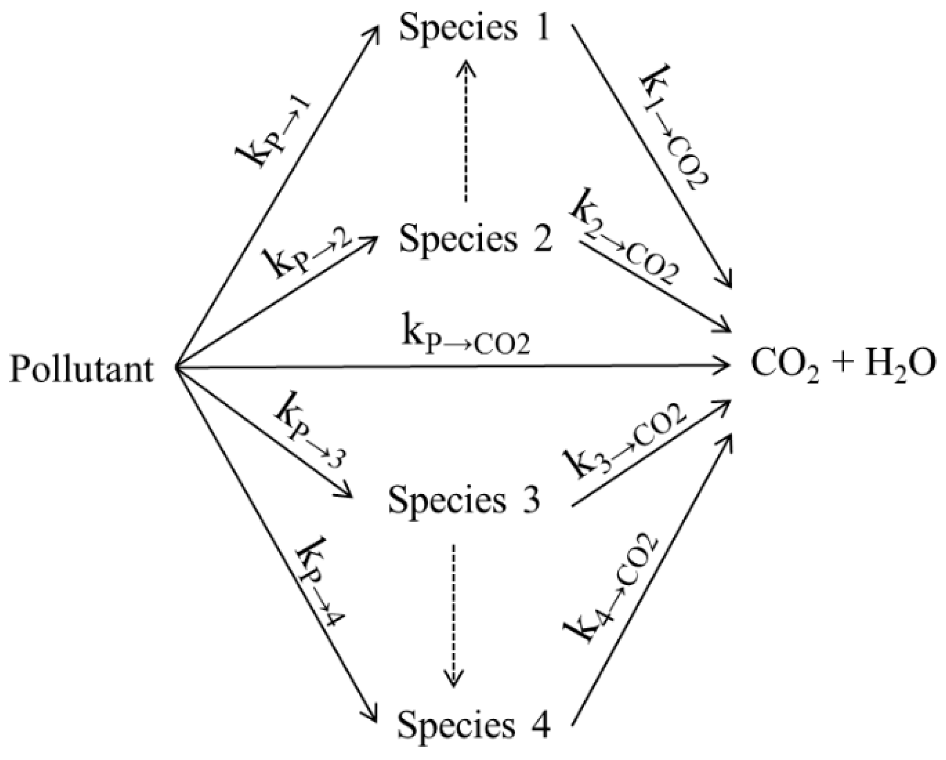
Different reaction mechanisms can be considered for the complete mineralization of VOCs into CO2 and H2O, with the “parallel-in series” method proving to be a most relevant approach for the photoconversion of organic pollutants in air and water.
(f)
Macroscopic irradiation energy balances are required to calculate the photons absorbed by the semiconductor material during PCO.
(g)
Tracking all chemical species, including model pollutants and intermediates, is required to assess OH consumption rates.
(h)
Quantum Yields provide energy efficiencies in photocatalytic reactors, with an adequate definition based on the ratio of OH radicals consumed over the rate of photons absorbed by the photocatalyst.
(i)
The PTEF is a valuable parameter to determine photocatalytic reactor efficiencies on the basis of thermodynamics principles.
(j)
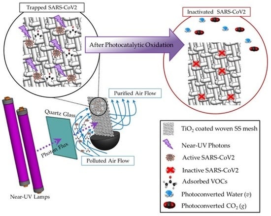
Photocatalytic reactors have the potential to be re-engineered for SARS-CoV2 (COVID-19) virus inactivation in hospitals and other indoor enclosed spaces. It is anticipated that this will be achieved with high IQYs (Inactivation Quantum Yields).

Author Contributions

Investigation, preparation and writing of the original-draft review article, S.E.; writing, review and editing of the manuscript, H.d.L. All authors have read and agreed to the published version of the manuscript.

Funding

This research was funded by Western University and the Natural Science and Engineering Research Council of Canada (NSERC), through grants awarded to Hugo de Lasa.

Acknowledgments

The authors would like to thank Florencia de Lasa, who assisted with the editing and proofreading of this manuscript.

Conflicts of Interest

The authors declare no conflict of interest.

Nomenclature

AUniformly irradiated mesh area holding an optimum loading of TiO2 (m2)
AgSilver
AuGold
cSpeed of light (3 × 10⁸ m/s)
CCarbon
Co(CH3CO2)2 Cobalt (II) acetate
C2H4OAcetaldehyde
C3H6OAcetone
Mn(CH3CO2)2Manganese (II) acetate
CO2Carbon dioxide
CoCobalt
CrChrome
C A c Acetone concentration (kg/m3)
Ceq,iEquilibrium of species “i” in the gas phase concentration (mol/m3 or ppm)
Ceq,InfInflection point observed on the adsorption isotherm (mol/m3)
DDiffusivity of acetone in air (m2/s)
Dp-BJHPore diameter (nm)
DtEddy diffusivity (m2/s)
e-Electron
EavAverage photon energy (kJ/mol photon).
EBGEnergy band gap (eV)
eVElectron volts
FeIron
Fe+3Iron-III
hPlanck’s constant (6.63 × 10⁻³⁴ J/s))
h+Hole
H2OWater
HNO3Nitric acid
KPermeability (m2)
kiEquilibrium kinetic constant of specie “i” (mol/s m3)
K e q , i A Adsorption equilibrium constant (m3/mol or ppm−1)
K e q , i A 1 Langmuir adsorption equilibrium constant (m3/mol or ppm−1)
K e q , i A 2 Freundlich adsorption equilibrium constant (m3/mol or ppm−1)
LLiters
MnManganese
MS2Non-pathogenicity to humans norovirus structure
nNumber of layers
NNitrogen (solid)
N2Nitrogen (gas)
NH3Ammonia
NH4FAmmonium fluoride
NH4VO3Ammonium metavanadate
NONitrogen oxide
NO2Nitrogen dioxide
[ N C ] i n Carbon atoms at initial conditions (atoms of carbon inactivated/s)
OOxidized
O2Oxygen
O2-Superoxide radicals
OHHydroxyl radicals
PaRate of absorbed photons (mol of photons/s).
P i     Incident radiation
P r Reflected radiation
P t     Transmitted radiation
PdPalladium
PtPlatinum
q (θ,z,λ)Radiation measured (W/cm2 nm)
Qeq, adsExisting equilibrium adsorption surface concentration (mol/gcat)
Qeq, maxMaximum equilibrium adsorption surface concentration (mol/gcat)
Qeq, max-1Langmuir maximum equilibrium adsorption surface concentrations (mol/gcat)
Qeq, max-2Freundlich maximum equilibrium adsorption surface concentrations (mol/gcat)
R+Reduced
SSulphur
SBETSurface Area (m2/g)
S C Acetone source/sink term (kg/m3 s)
S M Momentum source/sink term (kg/m2 s2)
tTime (s)
TiTitanium
TiCl4Titanium tetrachloride
TiO2Titanium dioxide
Ti(OCH(CH3)2)4Titanium tetraisopropoxide
VTotal volume in PCAR reactors (m3)
VVanadium
V2O5Vanadium (V) oxide
Vp-BJHPore volume (cm3/g)
W(CO6)Tungsten hexacarbonyle
wt.%Weight percent (%)
Acronyms
AAnatase
AAS-ASCAir Assisted Spray-Automatized Spinning Coating
BETBrunauer-Emmett-Teller
BJHBarrett-Joyner-Halenda
BTXBenzene-Toluene-Xylene
CBConduction Band
CFDComputational Fluid Dynamics
COVID-19Corona Virus -19 (SARS-CoV2)
CRECChemical Reactor Engineer Centre
CVDChemical Vapor Deposition
DBDebye Sherrer
DP25Degussa P25 (Commercial TiO2)
FQEFormal Quantum Efficiency
HEPAHigh-Efficiency Particulate Air Filter
IQYsInactivation Quantum Yields
LEDLight-Emitting Diode
LHLangmuir-Hinshelwood
MIEBMacroscopic Irradiation Energy Balances
PAHsPolycyclic Aromatic Hydrocarbons
PCARPhotocatalytic Oxidation
PFUParticle Forming Units
PTEFsPhotocatalytic Thermodynamic Efficiency Factors
PUPorous Polyurethane
QYsQuantum Yields
QYappApparent Quantum Yield
RRutile
RVERepresentative Volume Element
SARSSevere Acute Respiratory Syndrome
SSStainless Steel
SSTShear Stress Transport
UVUltraviolet
VBValence Band
VOCsVolatile Organic Compounds
VUVVacuum Ultraviolet
Symbols
θAngular position (°)
θ A Dimensionless surface species concentration
r i Rate of photoconversion of the model pollutant “i” (mol/min*m2)
H O H Enthalpy invested in the formation of the OH radicals (J/mol)
λRadiation wavelength (nm)
ρ Fluid density (kg/m3)
U Fluid velocity vector (m/s)
U S / U M a x Dimensionless ratio between the interface slip velocity
τ Stress tensor (N/m2)
τ t Reynolds stress tensor (N/m2)
ν Stoichiometric coefficient
rRadial position (cm)
n O H Fraction of photon energy used to form OH radicals
Gradient vector of x, y and z coordinates
Tensor product

References

  1. Nakano, R.; Ishiguro, H.; Yao, Y.; Kajioka, J.; Fujishima, A.; Sunada, K.; Minoshima, M.; Hashimoto, K.; Kubota, Y. Photocatalytic inactivation of influenza virus by titanium dioxide thin film. Photochem. Photobiol. Sci. 2012, 11, 1293–1298. [Google Scholar] [CrossRef]
  2. Ibrahim, H.; Lasa, H. de Photo-catalytic conversion of air borne pollutants Effect of catalyst type and catalyst loading in a novel photo-CREC-air unit. Appl. Catal. B Environ. 2002, 38, 201–213. [Google Scholar] [CrossRef]
  3. Lugo-Vega, C.S. Evaluation of VOC Degradation in Photo- Catalytic Air Reactors: TiO2 Immobilization, Energy Efficiency and Kinetic Modeling. Ph.D. Thesis, University of Western Ontario, London, ON, Canada, 2016. [Google Scholar]
  4. Hakim, M.; Broza, Y.Y.; Barash, O.; Peled, N.; Phillips, M.; Amann, A.; Haick, H. Volatile organic compounds of lung cancer and possible biochemical pathways. Chem. Rev. 2012, 112, 5949–5966. [Google Scholar] [CrossRef]
  5. Dales, R.; Liu, L.; Wheeler, A.J.; Gilbert, N.L. Quality of indoor residential air and health. Can. Med. Assoc. J. 2008, 179, 147–152. [Google Scholar] [CrossRef] [Green Version]
  6. Indoor Air Quality | EPA’s Report on the Environment (ROE) | US EPA. Available online: https://www.epa.gov/report-environment/indoor-air-quality (accessed on 20 April 2020).
  7. Klepeis, N.E.; Nelson, W.C.; Ott, W.R.; Robinson, J.P.; Tsang, A.M.; Switzer, P.; Behar, J.V.; Hern, S.C.; Engelmann, W.H. The National Human Activity Pattern Survey (NHAPS): A resource for assessing exposure to environmental pollutants. J. Expo. Anal. Environ. Epidemiol. 2001, 11, 231–252. [Google Scholar] [CrossRef] [PubMed] [Green Version]
  8. Garcia-Hernandez, J.M.; Serrano-Rosales, B.; De Lasa, H. Energy efficiencies in a photo-CREC-air reactor: Conversion of model organic pollutants in air. Ind. Eng. Chem. Res. 2012, 51, 5715–5727. [Google Scholar] [CrossRef]
  9. Castrillón, S.R.V.; De Lasa, H.I. Performance evaluation of photocatalytic reactors for air purification using Computational Fluid Dynamics (CFD). Ind. Eng. Chem. Res. 2007, 46, 5867–5880. [Google Scholar] [CrossRef]
  10. De Lasa, H.; Serrano, B.; Salaices, M. Photocatalytic Reaction Engineering, 1st ed.; Springer: Berlin/Heidelberg, Germany, 2005; ISBN 978-0-387-27591-8. [Google Scholar]
  11. Sirivallop, A.; Areerob, T.; Chiarakorn, S. Enhanced Visible Light Photocatalytic Activity of N and Ag Doped and Co-Doped TiO2 Synthesized by Using an In-Sity Solvothermal Method for Gas Phase Ammonia Removal. Catalysts 2020, 10, 251. [Google Scholar] [CrossRef] [Green Version]
  12. Lugo-Vega, C.S.; Serrano-Rosales, B.; de Lasa, H. Immobilized particle coating for optimum photon and TiO2 utilization in scaled air treatment photo reactors. Appl. Catal. B Environ. 2016, 198, 211–223. [Google Scholar] [CrossRef]
  13. Romero-Vargas Castrillón, S.; Ibrahim, H.; De Lasa, H. Flow field investigation in a photocatalytic reactor for air treatment (Photo-CREC-air). Chem. Eng. Sci. 2006, 61, 3343–3361. [Google Scholar] [CrossRef]
  14. Hernandez, J.M.G.; Rosales, B.S.; de Lasa, H. The photochemical thermodynamic efficiency factor (PTEF) in photocatalytic reactors for air treatment. Chem. Eng. J. 2010, 165, 891–901. [Google Scholar] [CrossRef]
  15. Lugo-Vega, C.S.; Serrano-Rosales, B.; de Lasa, H. Energy efficiency limits in Photo-CREC-Air photocatalytic reactors. Chem. Eng. Sci. 2016, 156, 77–88. [Google Scholar] [CrossRef]
  16. Ibrahim, H.; de Lasa, H. Photo-catalytic degradation of air borne pollutants apparent quantum efficiencies in a novel photo-CREC-air reactor. Chem. Eng. Sci. 2003, 58, 943–949. [Google Scholar] [CrossRef]
  17. Rusinque, B.; Escobedo, S.; de Lasa, H. Photocatalytic Hydrogen Production Under Near-UV Using Pd-Doped Mesoporous TiO2 and Ethanol as Organic Scavenger. Catalysts 2019, 9, 33. [Google Scholar] [CrossRef] [Green Version]
  18. Escobedo, S.; Serrano, B.; de Lasa, H. Quantum yield with platinum modified TiO2 photocatalyst for hydrogen production. Appl. Catal. B Environ. 2013, 523–536. [Google Scholar] [CrossRef]
  19. Rusinque, B.; Escobedo, S.; de Lasa, H. Photoreduction of a Pd-Doped Mesoporous TiO2 Photocatalyst for Hydrogen Production under Visible Light. Catalysts 2020, 10, 74. [Google Scholar] [CrossRef] [Green Version]
  20. Deng, X.; Yue, Y.; Gao, Z. Gas-phase photo-oxidation of organic compounds over nanosized TiO2 photocatalysts by various preparations. Appl. Catal. B Environ. 2002, 39, 135–147. [Google Scholar] [CrossRef]
  21. Benmami, M.; Chhor, K.; Kanaev, A.V. High photocatalytic activity of monolayer nanocoatings prepared from non-crystalline titanium oxide sol nanoparticles. Chem. Phys. Lett. 2006, 422, 552–557. [Google Scholar] [CrossRef]
  22. Esterkin, C.R.; Negro, A.C.; Alfano, O.M.; Cassano, A.E. Air pollution remediation in a fixed bed photocatalytic reactor coated with TiO2. AIChE J. 2003, 51, 2298–2310. [Google Scholar] [CrossRef]
  23. Peill, N.J.; Hoffmann, M.R. Development and Optimization of a TiO2-Coated Fiber-Optic Cable Reactor: Photocatalytic Degradation of 4-Chlorophenol. Environ. Sci. Technol. 1995, 29, 2974–2981. [Google Scholar] [CrossRef]
  24. Zhu, R.; Che, S.; Liu, X.; Lin, S.; Xu, G.; Ouyang, F. A novel fluidized-bed-optical-fibers photocatalytic reactor (FBOFPR) and its performance. Appl. Catal. A Gen. 2014, 471, 136–141. [Google Scholar] [CrossRef]
  25. Wu, Y.T.; Yu, Y.H.; Nguyen, V.H.; Lu, K.T.; Wu, J.C.S.; Chang, L.M.; Kuo, C.W. Enhanced xylene removal by photocatalytic oxidation using fiber-illuminated honeycomb reactor at ppb level. J. Hazard. Mater. 2013, 262, 717–725. [Google Scholar] [CrossRef] [PubMed]
  26. Du, P.; Carneiro, J.T.; Moulijn, J.A.; Mul, G. A novel photocatalytic monolith reactor for multiphase heterogeneous photocatalysis. Appl. Catal. A Gen. 2008, 334, 119–128. [Google Scholar] [CrossRef]
  27. Monteiro, R.A.R.; Miranda, S.M.; Rodrigues-Silva, C.; Faria, J.L.; Silva, A.M.T.; Boaventura, R.A.R.; Vilar, V.J.P. Gas phase oxidation of n-decane and PCE by photocatalysis using an annular photoreactor packed with a monolithic catalytic bed coated with P25 and PC500. Appl. Catal. B Environ. 2015, 165, 306–315. [Google Scholar] [CrossRef] [Green Version]
  28. Han, Z.; Chang, V.W.C.; Zhang, L.; Tse, M.S.; Tan, O.K.; Hildemann, L.M. Preparation of TiO2-coated polyester fiber filter by spray-coating and its photocatalytic degradation of gaseous formaldehyde. Aerosol Air Qual. Res. 2012, 12, 1327–1335. [Google Scholar] [CrossRef] [Green Version]
  29. Birnie, M.; Riffat, S.; Gillott, M. Photocatalytic reactors: Design for effective air purification. Int. J. Low-Carbon Technol. 2006, 1, 47–58. [Google Scholar] [CrossRef] [Green Version]
  30. Hou, W.M.; Ku, Y. Photocatalytic decomposition of gaseous isopropanol in a tubular optical fiber reactor under periodic UV-LED illumination. J. Mol. Catal. A Chem. 2013, 374–375, 7–11. [Google Scholar] [CrossRef]
  31. Ibrahim, H.; De Lasa, H. Kinetic Modeling of the Photocatalytic Degradation of Air-Borne Pollutants. AIChE J. 2004, 50, 1017–1027. [Google Scholar] [CrossRef]
  32. Kočí, K.; Reli, M.; Kozák, O.; Lacný, Z.; Plachá, D.; Praus, P.; Obalová, L. Influence of reactor geometry on the yield of CO2 photocatalytic reduction. Catal. Today 2011, 176, 212–214. [Google Scholar] [CrossRef]
  33. Lugo-Vega, C.S.; Moreira, J.; Serrano-Rosales, B.; de Lasa, H. Kinetics of the pollutant photocatalytic conversion in a Photo-CREC-Air Reactor. Chem. Eng. J. 2017, 317, 1069–1082. [Google Scholar] [CrossRef]
  34. Escobedo, S.; Serrano, B.; Calzada, A.; Moreira, J.; de Lasa, H. Hydrogen production using a platinum modified TiO2 photocatalyst and an organic scavenger. Kinetic modeling. Fuel 2016, 181, 438–449. [Google Scholar] [CrossRef]
  35. Vincent, G.; Schaer, E.; Marquaire, P.M.; Zahraa, O. CFD modelling of an annular reactor, application to the photocatalytic degradation of acetone. Process Saf. Environ. Prot. 2011, 89, 35–40. [Google Scholar] [CrossRef]
  36. Boyjoo, Y.; Ang, M.; Pareek, V. Some aspects of photocatalytic reactor modeling using computational fluid dynamics. Chem. Eng. Sci. 2013, 101, 764–784. [Google Scholar] [CrossRef]
  37. Queffeulou, A.; Geron, L.; Schaer, E. Prediction of photocatalytic air purifier apparatus performances with a CFD approach using experimentally determined kinetic parameters. Chem. Eng. Sci. 2010, 65, 5067–5074. [Google Scholar] [CrossRef]
  38. Ibrahim, H.; De Lasa, H. Novel photocatalytic reactor for the destruction of airborne pollutants reaction kinetics and quantum yields. Ind. Eng. Chem. Res. 1999, 38, 3211–3217. [Google Scholar] [CrossRef]
  39. Garcia-Segura, S.; Dosta, S.; Guilemany, J.M.; Brillas, E. Solar photoelectrocatalytic degradation of Acid Orange 7 azo dye using a highly stable TiO2 photoanode synthesized by atmospheric plasma spray. Appl. Catal. B Environ. 2013, 132–133, 142–150. [Google Scholar] [CrossRef]
  40. Houas, A.; Lachheb, H.; Ksibi, M.; Elaloui, E.; Guillard, C.; Herrmann, J.M. Photocatalytic degradation pathway of methylene blue in water. Appl. Catal. B Environ. 2001, 31, 145–157. [Google Scholar] [CrossRef]
  41. Zhao, J.; Chen, C.; Ma, W. Photocatalytic Degradation of Organic Pollutants Under Visible Light Irradiation. Top. Catal. 2005, 35, 269–278. [Google Scholar] [CrossRef]
  42. Kudo, A.; Miseki, Y. Heterogeneous photocatalyst materials for water splitting. Chem. Soc. Rev. 2009, 38, 253–278. [Google Scholar] [CrossRef]
  43. Serrano, B.; Ortíz, A.; Moreira, J.; De Lasa, H.I. Energy efficiency in photocatalytic reactors for the full span of reaction times. Ind. Eng. Chem. Res. 2009, 48, 9864–9876. [Google Scholar] [CrossRef]
  44. Escobedo, S.; Rusinque, B.; de Lasa, H. Photochemical Thermodynamic Efficiency Factors (PTEFs) for Hydrogen Production Using Different TiO2 Photocatalysts. Ind. Eng. Chem. Res. 2019, 58, 22225–22235. [Google Scholar] [CrossRef]
  45. Serrano, B.; Ortíz, A.; Moreira, J.; De Lasa, H.I. Photocatalytic thermodynamic efficiency factors. Practical limits in photocatalytic reactors. Ind. Eng. Chem. Res. 2010, 49, 6824–6833. [Google Scholar] [CrossRef]
  46. Keller, V.; Keller, N.; Ledoux, M.J.; Lett, M.C. Biological agent inactivation in a flowing air stream by photocatalysis. Chem. Commun. 2005, 2918–2920. [Google Scholar] [CrossRef]
  47. Gerrity, D.; Ryu, H.; Crittenden, J.; Abbaszadegan, M. Photocatalytic inactivation of viruses using titanium dioxide nanoparticles and low-pressure UV light. J. Environ. Sci. Heal.—Part A Toxic/Hazardous Subst. Environ. Eng. 2008, 43, 1261–1270. [Google Scholar] [CrossRef] [PubMed]
  48. Kim, J.; Jang, J. Inactivation of airborne viruses using vacuum ultraviolet photocatalysis for a flow-through indoor air purifier with short irradiation time. Aerosol Sci. Technol. 2018, 52, 557–566. [Google Scholar] [CrossRef] [Green Version]
  49. Yao, Y.; Ochiai, T.; Ishiguro, H.; Nakano, R.; Kubota, Y. Antibacterial performance of a novel photocatalytic-coated cordierite foam for use in air cleaners. Appl. Catal. B Environ. 2011, 106, 592–599. [Google Scholar] [CrossRef] [PubMed]
  50. Bedia, J.; Muelas-Ramos, V.; Peñas-Garzón, M.; Gómez-Avilés, A.; Rodríguez, J.J.; Belver, C. A review on the synthesis and characterization of metal organic frameworks for photocatalytic water purification. Catalysts 2019, 9, 52. [Google Scholar] [CrossRef] [Green Version]
  51. Fujishima, A.; Zhang, X. Titanium dioxide photocatalysis: Present situation and future approaches. Comptes Rendus Chim. 2006, 9, 750–760. [Google Scholar] [CrossRef]
  52. Ismail, A.A.; Bahnemann, D.W. Mesoporous titania photocatalysts: Preparation, characterization and reaction mechanisms. J. Mater. Chem. 2011, 21, 11686–11707. [Google Scholar] [CrossRef] [Green Version]
  53. Salaices, M.; Serrano, B.; De Lasa, H.I. Photocatalytic conversion of organic pollutants extinction coefficients and quantum efficiencies. Ind. Eng. Chem. Res. 2001, 40, 5455–5464. [Google Scholar] [CrossRef]
  54. Rosales, B.S.; Moreira Del Rio, J.; Guayaquil, J.F.; De Lasa, H. Photodegradation Efficiencies in a Photo-CREC Water-II Reactor Using Several TiO2 Based Catalysts. Int. J. Chem. React. Eng. 2016, 14, 685–701. [Google Scholar] [CrossRef]
  55. Bianchi, C.L.; Gatto, S.; Pirola, C.; Naldoni, A.; Di Michele, A.; Cerrato, G.; Crocellà, V.; Capucci, V. Photocatalytic degradation of acetone, acetaldehyde and toluene in gas-phase: Comparison between nano and micro-sized TiO2. Appl. Catal. B Environ. 2014, 146, 123–130. [Google Scholar] [CrossRef]
  56. Haghighatmamaghani, A.; Haghighat, F.; Lee, C.S. Performance of various commercial TiO2 in photocatalytic degradation of a mixture of indoor air pollutants: Effect of photocatalyst and operating parameters. Sci. Technol. Built Environ. 2019, 25, 600–614. [Google Scholar] [CrossRef]
  57. Nuño, M.; Ball, R.J.; Bowen, C.R. Photocatalytic Properties of Commercially Available TiO2 Powders for Pollution Control. In Semiconductor Photocatalysis—Materials, Mechanisms and Applications; InTech: Vienna, Austria, 2016. [Google Scholar] [CrossRef] [Green Version]
  58. Sun, H.; Ullah, R.; Chong, S.; Ang, H.M.; Tadé, M.O.; Wang, S. Room-light-induced indoor air purification using an efficient Pt/N-TiO2 photocatalyst. Appl. Catal. B Environ. 2011, 108–109, 127–133. [Google Scholar] [CrossRef]
  59. Christoforidis, K.C.; Figueroa, S.J.A.; Fernández-García, M. Iron-sulfur codoped TiO2 anatase nano-materials: UV and sunlight activity for toluene degradation. Appl. Catal. B Environ. 2012, 117–118, 310–316. [Google Scholar] [CrossRef]
  60. Pham, T.D.; Lee, B.K. Novel adsorption and photocatalytic oxidation for removal of gaseous toluene by V-doped TiO2/PU under visible light. J. Hazard. Mater. 2015, 300, 493–503. [Google Scholar] [CrossRef]
  61. Gurulakshmi, M.; Selvaraj, M.; Selvamani, A.; Vijayan, P.; Sasi Rekha, N.R.; Shanthi, K. Enhanced visible-light photocatalytic activity of V2O5/S-TiO2 nanocomposites. Appl. Catal. A Gen. 2012, 449, 31–46. [Google Scholar] [CrossRef]
  62. Almomani, F.; Bhosale, R.; Shawaqfah, M. Solar oxidation of toluene over Co doped nano-catalyst. Chemosphere 2020, 255, 126878. [Google Scholar] [CrossRef]
  63. Huang, H.; Huang, H.; Zhang, L.; Hu, P.; Ye, X.; Leung, D.Y.C. Enhanced degradation of gaseous benzene under vacuum ultraviolet (VUV) irradiation over TiO2 modified by transition metals. Chem. Eng. J. 2015, 259, 534–541. [Google Scholar] [CrossRef]
  64. Zhu, S.; Wang, D. Photocatalysis: Basic principles, diverse forms of implementations and emerging scientific opportunities. Adv. Energy Mater. 2017, 7, 1–24. [Google Scholar] [CrossRef] [Green Version]
  65. Liu, L.; Li, Y. Understanding the reaction mechanism of photocatalytic reduction of CO2 with H2O on TiO2-based photocatalysts: A review. Aerosol Air Qual. Res. 2014, 14, 453–469. [Google Scholar] [CrossRef]
  66. Ajmal, A.; Majeed, I.; Malik, R.N.; Idriss, H.; Nadeem, M.A. Principles and mechanisms of photocatalytic dye degradation on TiO2 based photocatalysts: A comparative overview. RSC Adv. 2014, 4, 37003–37026. [Google Scholar] [CrossRef]
  67. Hirakawa, T.; Koga, C.; Negishi, N.; Takeuchi, K.; Matsuzawa, S. An approach to elucidating photocatalytic reaction mechanisms by monitoring dissolved oxygen: Effect of H2O2 on photocatalysis. Appl. Catal. B Environ. 2009, 87, 46–55. [Google Scholar] [CrossRef]
  68. Yang, Y.; Zhong, H.; Tian, C. Photocatalytic mechanisms of modified titania under visible light. Res. Chem. Intermed. 2011, 37, 91–102. [Google Scholar] [CrossRef]
  69. Wang, K.; Tsai, H.; Hsieh, Y. A study of photocatalytic degradation of trichloroethylene in vapor phase on TiO2 photocatalyst. Chemosphere 1998, 36, 2763–2773. [Google Scholar] [CrossRef]
  70. Barakat, C.; Gravejat, P.; Guaitella, O.; Thevenet, F.; Rousseau, A. Oxidation of isopropanol and acetone adsorbed on TiO2 under plasma generated ozone flow: Gas phase and adsorbed species monitoring. Appl. Catal. B Environ. 2014, 147, 302–313. [Google Scholar] [CrossRef]
  71. Kim, M.S.; Liu, G.; Nam, W.K.; Kim, B.W. Preparation of porous carbon-doped TiO2 film by sol-gel method and its application for the removal of gaseous toluene in the optical fiber reactor. J. Ind. Eng. Chem. 2011, 17, 223–228. [Google Scholar] [CrossRef]
  72. Yang, G.; Jiang, Z.; Shi, H.; Xiao, T.; Yan, Z. Preparation of highly visible-light active N-doped TiO2 photocatalyst. J. Mater. Chem. 2010, 20, 5301–5309. [Google Scholar] [CrossRef]
  73. Li, D.; Haneda, H.; Hishita, S.; Ohashi, N. Visible-light-driven N-F-codoped TiO2 photocatalysts. 1. Synthesis by spray pyrolysis and surface characterization. Chem. Mater. 2005, 17, 2588–2595. [Google Scholar] [CrossRef]
  74. Salas, S.E.; Hugo De Lasa, S. Photocatalytic Water Splitting using a Modified Pt- TiO2. Kinetic Modeling and Hydrogen Production Efficiency. Ph.D. Thesis, University of Western Ontario, London, ON, Canada, 2013. [Google Scholar]
  75. Imoberdorf, G.E.; Irazoqui, H.A.; Alfano, O.M.; Cassano, A.E. Scaling-up from first principles of a photocatalytic reactor for air pollution remediation. Chem. Eng. Sci. 2007, 62, 793–804. [Google Scholar] [CrossRef]
  76. Arsac, F.; Bianchi, D.; Chovelon, J.M.; Conchon, P.; Ferronato, C.; Lair, A.; Sleiman, M. Photocatalytic degradation of organic pollutants in water and in air. An analytical approach. Mater. Sci. Eng. C 2008, 28, 722–725. [Google Scholar] [CrossRef]
  77. Debono, O.; Thevenet, F.; Gravejat, P.; Hequet, V.; Raillard, C.; Lecoq, L.; Locoge, N. Toluene photocatalytic oxidation at ppbv levels: Kinetic investigation and carbon balance determination. Appl. Catal. B Environ. 2011, 106, 600–608. [Google Scholar] [CrossRef]
  78. Debono, O.; Thévenet, F.; Gravejat, P.; Héquet, V.; Raillard, C.; Le Coq, L.; Locoge, N. Gas phase photocatalytic oxidation of decane at ppb levels: Removal kinetics, reaction intermediates and carbon mass balance. J. Photochem. Photobiol. A Chem. 2013, 258, 17–29. [Google Scholar] [CrossRef]
  79. Zhong, L.; Haghighat, F.; Lee, C.S.; Lakdawala, N. Performance of ultraviolet photocatalytic oxidation for indoor air applications: Systematic experimental evaluation. J. Hazard. Mater. 2013, 261, 130–138. [Google Scholar] [CrossRef] [PubMed]
  80. Dong, F.; Wang, Z.; Li, Y.; Ho, W.K.; Lee, S.C. Immobilization of polymeric g-C3N4 on structured ceramic foam for efficient visible light photocatalytic air purification with real indoor illumination. Environ. Sci. Technol. 2014, 48, 10345–10353. [Google Scholar] [CrossRef]
  81. Nuño, M.; Ball, R.J.; Bowen, C.R. Study of solid/gas phase photocatalytic reactions by electron ionization mass spectrometry. J. Mass Spectrom. 2014, 49, 716–726. [Google Scholar] [CrossRef] [Green Version]
  82. Imoberdorf, G.E.; Cassano, A.E.; Irazoqui, H.A.; Alfano, O.M. Optimal design and modeling of annular photocatalytic wall reactors. Catal. Today 2007, 129, 118–126. [Google Scholar] [CrossRef]
  83. Imoberdorf, G.E.; Irazoqui, H.A.; Cassano, A.E.; Alfano, O.M. Photocatalytic Degradation of Tetrachloroethylene in Gas Phase on TiO2 Films: A Kinetic Study. Ind. Eng. Chem. Res. 2005, 44, 6075–6085. [Google Scholar] [CrossRef]
  84. Héquet, V.; Batault, F.; Raillard, C.; Thévenet, F.; Le Coq, L.; Dumont, É. Determination of the clean air delivery rate (CADR) of photocatalytic oxidation (PCO) purifiers for indoor air pollutants using a closed-loop reactor. Part II: Experimental results. Molecules 2017, 22, 408. [Google Scholar] [CrossRef] [Green Version]
  85. Xu, T.; Zheng, H.; Zhang, P. Performance of an innovative VUV-PCO purifier with nanoporous TiO2 film for simultaneous elimination of VOCs and by-product ozone in indoor air. Build. Environ. 2018, 142, 379–387. [Google Scholar] [CrossRef]
  86. Onoda, K.; Yoshikawa, S. Applications of anodized TiO2 films for environmental purifications. Appl. Catal. B Environ. 2008, 80, 277–285. [Google Scholar] [CrossRef]
  87. Taranto, J.; Frochot, D.; Pichat, P. Photocatalytic treatment of air: Comparison of various TiO2, coating methods, and supports using methanol or n-Octane as tst pollutant. Ind. Eng. Chem. Res. 2009, 48, 6229–6236. [Google Scholar] [CrossRef]
  88. El-Kalliny, A.S.; Ahmed, S.F.; Rietveld, L.C.; Appel, P.W. Immobilized photocatalyst on stainless steel woven meshes assuring efficient light distribution in a solar reactor. Drink. Water Eng. Sci. 2014, 7, 41–52. [Google Scholar] [CrossRef] [Green Version]
  89. Monteiro, R.A.R.; Silva, A.M.T.; Ângelo, J.R.M.; Silva, G.V.; Mendes, A.M.; Boaventura, R.A.R.; Vilar, V.J.P. Photocatalytic oxidation of gaseous perchloroethylene over TiO2 based paint. J. Photochem. Photobiol. A Chem. 2015, 311, 41–52. [Google Scholar] [CrossRef] [Green Version]
  90. Pulišová, P.; Boháček, J.; Šubrt, J.; Szatmáry, L.; Bezdička, P.; Večerníková, E.; Balek, V. Thermal behaviour of titanium dioxide nanoparticles prepared by precipitation from aqueous solutions. J. Therm. Anal. Calorim. 2010, 101, 607–613. [Google Scholar] [CrossRef]
  91. Motola, M.; Satrapinskyy, L.; Roch, T.; Šubrt, J.; Kupčík, J.; Klementová, M.; Jakubičková, M.; Peterka, F.; Plesch, G. Anatase TiO2 nanotube arrays and titania films on titanium mesh for photocatalytic NOX removal and water cleaning. Catal. Today 2017, 287, 59–64. [Google Scholar] [CrossRef]
  92. Ma, C.M.; Ku, Y.; Kuo, Y.L.; Chou, Y.C.; Jeng, F.T. Effects of silver on the photocatalytic degradation of gaseous Isopropanol. Water. Air. Soil Pollut. 2009, 197, 313–321. [Google Scholar] [CrossRef]
  93. Xu, W.; Raftery, D. Photocatalytic oxidation of 2-propanol on TiO2 powder and TiO2 monolayer catalysts studied by solid-state NMR. J. Phys. Chem. B 2001, 105, 4343–4349. [Google Scholar] [CrossRef]
  94. Ao, C.H.; Lee, S.C.; Mak, C.L.; Chan, L.Y. Photodegradation of volatile organic compounds (VOCs) and NO for indoor air purification using TiO2: Promotion versus inhibition effect of NO. Appl. Catal. B Environ. 2003, 42, 119–129. [Google Scholar] [CrossRef]
  95. Marinangeli, R.E.; Ollis, D.F. Photo-assisted heterogeneous catalysis with optical fibers II. Nonisothermal single fiber and fiber bundle. AIChE J. 1980, 26, 1000–1008. [Google Scholar] [CrossRef]
  96. Verbruggen, S.W.; Ribbens, S.; Tytgat, T.; Hauchecorne, B.; Smits, M.; Meynen, V.; Cool, P.; Martens, J.A.; Lenaerts, S. The benefit of glass bead supports for efficient gas phase photocatalysis: Case study of a commercial and a synthesised photocatalyst. Chem. Eng. J. 2011, 174, 318–325. [Google Scholar] [CrossRef]
  97. Hachem, C.; Bocquillon, F.; Zahraa, O.; Bouchy, M. Decolourization of textile industry wastewater by the photocatalytic degradation process. Dye. Pigment. 2001, 49, 117–125. [Google Scholar] [CrossRef]
  98. Doll, T.E.; Frimmel, F.H. Development of easy and reproducible immobilization techniques using TiO2 for photocatalytic degradation of aquatic pollutants. Acta Hydrochim. Hydrobiol. 2004, 32, 201–213. [Google Scholar] [CrossRef]
  99. Herrmann, J.M.; Tahiri, H.; Ait-Ichou, Y.; Lassaletta, G.; González-Elipe, A.R.; Fernandez, A. Characterization and photocatalytic activity in aqueous medium of TiO2 and Ag-TiO2 coatings on quartz. Appl. Catal. B Environ. 1997, 13, 219–228. [Google Scholar] [CrossRef]
  100. Fernández, A.; Lassaletta, G.; Jiménez, V.M.; Justo, A.; González-Elipe, A.R.; Herrmann, J.M.; Tahiri, H.; Ait-Ichou, Y. Preparation and characterization of TiO2 photocatalysts supported on various rigid supports (glass, quartz and stainless steel). Comparative studies of photocatalytic activity in water purification. Appl. Catal. B Environ. 1995, 7, 49–63. [Google Scholar] [CrossRef]
  101. Rodgher, V.; Moreira, J.; de Lasa, H.; Serrano, B. Photocatalytic degradation of malic acid using a thin coated TiO2 -film: Insights on the mechanism of photocatalysis. AIChE J. 2014, 60, 3286–3299. [Google Scholar] [CrossRef]
  102. Harizanov, O.; Harizanova, A. Development and investigation of sol-gel solutions for the formation of TiO2 coatings. Sol. Energy Mater. Sol. Cells 2000, 63, 185–195. [Google Scholar] [CrossRef]
  103. Yamazaki-Nishida, S.; Nagano, K.; Phillips, L.A.; Cervera-March, S.; Anderson, M.A. Photocatalytic degradation of trichloroethylene in the gas phase using titanium dioxide pelle. J. Photochem. Photobiol. A Chem. 1993, 70, 95–99. [Google Scholar] [CrossRef]
  104. Singh, A.K.; Singh, J.K. Fabrication of durable superhydrophobic coatings on cotton fabrics with photocatalytic activity by fluorine-free chemical modification for dual-functional water purification. New J. Chem. 2017, 41, 4618–4628. [Google Scholar] [CrossRef]
  105. Langlet, M.; Kim, A.; Audier, M.; Herrmann, J.M. Sol-gel preparation of photocatalytic TiO2 films on polymer substrates. J. Sol-Gel Sci. Technol. 2002, 25, 223–234. [Google Scholar] [CrossRef]
  106. Yamazaki, S.; Tanimura, T.; Yoshida, A.; Hori, K. Reaction mechanism of photocatalytic degradation of chlorinated ethylenes on porous TiO2 pellets: Cl radical-initiated mechanism. J. Phys. Chem. A 2004, 108, 5183–5188. [Google Scholar] [CrossRef]
  107. Harizanov, O.A.; Gesheva, K.A.; Stefchev, P.L. Sol-gel and CVD-metal oxide coatings for solar energy utilization. Ceram. Int. 1996, 22, 91–94. [Google Scholar] [CrossRef]
  108. Rachel, A.; Subrahmanyam, M.; Boule, P. Comparison of photocatalytic efficiencies of TiO2 in suspended and immobilised form for the photocatalytic degradation of nitrobenzenesulfonic acids. Appl. Catal. B Environ. 2002, 37, 301–308. [Google Scholar] [CrossRef]
  109. Farhanian, D.; Haghighat, F.; Lee, C.S.; Lakdawala, N. Impact of design parameters on the performance of ultraviolet photocatalytic oxidation air cleaner. Build. Environ. 2013, 66, 148–157. [Google Scholar] [CrossRef]
  110. Zhong, L.; Haghighat, F. Photocatalytic air cleaners and materials technologies—Abilities and limitations. Build. Environ. 2015, 91, 191–203. [Google Scholar] [CrossRef]
  111. Salaices, M.; Serrano, B.; de Lasa, H.I. Photocatalytic conversion of phenolic compounds in slurry reactors. Chem. Eng. Sci. 2004, 59, 3–15. [Google Scholar] [CrossRef]
  112. Moreira, J.; Serrano, B.; Ortiz, A.; de Lasa, H. A unified kinetic model for phenol photocatalytic degradation over TiO2 photocatalysts. Chem. Eng. Sci. 2012, 78, 186–203. [Google Scholar] [CrossRef]
  113. Legrini, O.; Oliveros, E.; Braun, A.M. Photochemical Processes for Water Treatment. Chem. Rev. 1993, 93, 671–698. [Google Scholar] [CrossRef]
  114. Ortiz-Gomez, A.; Serrano-Rosales, B.; Salaices, M.; De Lasa, H. Photocatalytic oxidation of phenol: Reaction network, kinetic modeling, and parameter estimation. Ind. Eng. Chem. Res. 2007, 46, 7394–7409. [Google Scholar] [CrossRef]
  115. Guayaquil, J.F.; Escobedo, S.; Calzada, A.; Serrano, B.; de Lasa, H. Hydrogen Production via Water Dissociation Using Pt–TiO2 Photocatalysts: An Oxidation–Reduction Network. Catalysts 2017, 7, 324. [Google Scholar] [CrossRef] [Green Version]
  116. Yu, Q.L.; Ballari, M.M.; Brouwers, H.J.H. Indoor air purification using heterogeneous photocatalytic oxidation. Part II: Kinetic study. Appl. Catal. B Environ. 2010, 99, 58–65. [Google Scholar] [CrossRef]
  117. Besov, A.S.; Vorontsov, A.V.; Parmon, V.N. Fast adsorptive and photocatalytic purification of air from acetone and dimethyl methylphosphonate by TiO2 aerosol. Appl. Catal. B Environ. 2009, 89, 602–612. [Google Scholar] [CrossRef]
  118. Boulamanti, A.K.; Philippopoulos, C.J. Photocatalytic degradation of C5-C7 alkanes in the gas-phase. Atmos. Environ. 2009, 43, 3168–3174. [Google Scholar] [CrossRef]
  119. Weibel, A.; Bouchet, R.; Knauth, P. Electrical properties and defect chemistry of anatase (TiO2). Solid State Ionics 2006, 177, 229–236. [Google Scholar] [CrossRef] [Green Version]
  120. Sauer, L.M.; Ollis, F.D. Acetone Oxidation in Photocatalytic Monolith Reactor. J. Catal. 1994, 149, 81–94. [Google Scholar] [CrossRef]
  121. Trong On, D.; Desplantier-Giscard, D.; Danumah, C.; Kaliaguine, S. ChemInform Abstract: Perspectives in Catalytic Applications of Mesostructured Materials. ChemInform 2010, 33, 299–357. [Google Scholar] [CrossRef]
  122. Maudhuit, A.; Raillard, C.; Héquet, V.; Le Coq, L.; Sablayrolles, J.; Molins, L. Adsorption phenomena in photocatalytic reactions: The case of toluene, acetone and heptane. Chem. Eng. J. 2011, 170, 464–470. [Google Scholar] [CrossRef]
  123. Obee, T.N. Photooxidation of sub-parts-per-million toluene and formaldehyde levels on titania using a glass-plate reactor. Environ. Sci. Technol. 1996, 30, 3578–3584. [Google Scholar] [CrossRef]
  124. Ding, X.; An, T.; Li, G.; Zhang, S.; Chen, J.; Yuan, J.; Zhao, H.; Chen, H.; Sheng, G.; Fu, J. Preparation and characterization of hydrophobic TiO2 pillared clay: The effect of acid hydrolysis catalyst and doped Pt amount on photocatalytic activity. J. Colloid Interface Sci. 2008, 320, 501–507. [Google Scholar] [CrossRef]
  125. Zhang, Y.P.; Yang, R.; Xu, Q.J.; Mo, J.H. Characteristics of photocatalytic oxidation of toluene, benzene, and their mixture. J. Air Waste Manag. Assoc. 2007, 57, 94–101. [Google Scholar] [CrossRef]
  126. Chin, P.; Yang, L.P.; Ollis, D.F. Formaldehyde removal from air via a rotating adsorbent combined with a photocatalyst reactor: Kinetic modeling. J. Catal. 2006, 237, 29–37. [Google Scholar] [CrossRef]
  127. Chen, W.; Zhang, J.S. UV-PCO device for indoor VOCs removal: Investigation on multiple compounds effect. Build. Environ. 2008, 43, 246–252. [Google Scholar] [CrossRef]
  128. Zhong, L.; Haghighat, F.; Blondeau, P.; Kozinski, J. Modeling and physical interpretation of photocatalytic oxidation efficiency in indoor air applications. Build. Environ. 2010, 45, 2689–2697. [Google Scholar] [CrossRef]
  129. Salvadores, F.; Alfano, O.M.; Ballari, M.M. Kinetic study of air treatment by photocatalytic paints under indoor radiation source: Influence of ambient conditions and photocatalyst content. Appl. Catal. B Environ. 2020, 268, 118694. [Google Scholar] [CrossRef]
  130. Yuan, Y.; Zheng, J.; Zhang, X.; Li, Z.; Yu, T.; Ye, J.; Zou, Z. BaCeO3 as a novel photocatalyst with 4f electronic configuration for water splitting. Solid State Ionics 2008, 178, 1711–1713. [Google Scholar] [CrossRef]
  131. Jacoby, W.A.; Blake, D.M.; Noble, R.D.; Koval, C.A. Kinetics of theoxidation of trichloroethylene in air via heterogeneous photocatalysis. J. Catal. 1995, 157, 87–96. [Google Scholar] [CrossRef]
  132. Baxter, R.J.; Hu, P. Insight into why the Langmuir-Hinshelwood mechanism is generally preferred. J. Chem. Phys. 2002, 116, 4379–4381. [Google Scholar] [CrossRef]
  133. Vincent, G.; Marquaire, P.M.; Zahraa, O. Photocatalytic degradation of gaseous 1-propanol using an annular reactor: Kinetic modelling and pathways. J. Hazard. Mater. 2009, 161, 1173–1181. [Google Scholar] [CrossRef]
  134. Zhong, L.; Haghighat, F. Modeling and validation of a photocatalytic oxidation reactor for indoor environment applications. Chem. Eng. Sci. 2011, 66, 5945–5954. [Google Scholar] [CrossRef]
  135. Lopes, F.V.S.; Monteiro, R.A.R.; Silva, A.M.T.; Silva, G.V.; Faria, J.L.; Mendes, A.M.; Vilar, V.J.P.; Boaventura, R.A.R. Insights into UV-TiO2 photocatalytic degradation of PCE for air decontamination systems. Chem. Eng. J. 2012, 204–205, 244–257. [Google Scholar] [CrossRef]
  136. Vorontsov, A.V.; Stoyanova, I.V.; Kozlov, D.V.; Simagina, V.I.; Savinov, E.N. Kinetics of the photocatalytic oxidation of gaseous acetone over platinized titanium dioxide. J. Catal. 2000, 189, 360–369. [Google Scholar] [CrossRef]
  137. Valadés-Pelayo, P.J.; Guayaquil Sosa, F.; Serrano, B.; de Lasa, H. Eight-lamp externally irradiated bench-scale photocatalytic reactor: Scale-up and performance prediction. Chem. Eng. J. 2015, 282, 142–151. [Google Scholar] [CrossRef]
  138. Fuller, E.N.; Schettler, P.D.; Giddings, J.C. A new method for prediction of binary gas-phase diffusion coefficients. Ind. Eng. Chem. 1966, 58, 18–27. [Google Scholar] [CrossRef]
  139. Degrave, R.; Moreau, J.; Cockx, A.; Schmitz, P. Multiscale analysis and modelling of fluid flow within a photocatalytic textile. Chem. Eng. Sci. 2015, 130, 264–274. [Google Scholar] [CrossRef] [Green Version]
  140. Cassano, A.E.; Martín, C.A.; Brandi, R.J.; Alfano, O.M. Photoreactor Analysis and Design: Fundamentals and Applications. Ind. Eng. Chem. Res. 1995, 34, 2155–2201. [Google Scholar] [CrossRef]
  141. Davydov, L.; Smirniotis, P.G.; Pratsinis, S.E. Novel differential reactor for the measurement of overall quantum yields. Ind. Eng. Chem. Res. 1999, 38, 1376–1383. [Google Scholar] [CrossRef]
  142. Valadés-Pelayo, P.J.; Moreira del Rio, J.; Solano-Flores, P.; Serrano, B.; de Lasa, H. Establishing photon absorption fields in a Photo-CREC Water II Reactor using a CREC-spectroradiometric probe. Chem. Eng. Sci. 2014, 116, 406–417. [Google Scholar] [CrossRef]
  143. Serrano, B.; De Lasa, H. Photocatalytic Degradation of Water Organic Pollutants. Kinetic Modeling and Energy Efficiency. Ind. Eng. Chem. Res. 1997, 36, 4705–4711. [Google Scholar] [CrossRef]
  144. Tran Thi Thuong, H.; Tran Thi Kim, C.; Nguyen Quang, L.; Kosslick, H. Highly active brookite TiO2-assisted photocatalytic degradation of dyes under the simulated solar−UVA radiation. Prog. Nat. Sci. Mater. Int. 2019, 29, 641–647. [Google Scholar] [CrossRef]
  145. Di Paola, A.; Addamo, M.; Bellardita, M.; Cazzanelli, E.; Palmisano, L. Preparation of photocatalytic brookite thin films. Thin Solid Films 2007, 515, 3527–3529. [Google Scholar] [CrossRef]
  146. Jin, J.; Chen, S.; Wang, J.; Chen, C.; Peng, T. SrCO3 -modified brookite/anatase TiO2 heterophase junctions with enhanced activity and selectivity of CO2 photoreduction to CH4. Appl. Surf. Sci. 2019, 476, 937–947. [Google Scholar] [CrossRef]
  147. Cao, S.; Chan, T.S.; Lu, Y.R.; Shi, X.; Fu, B.; Wu, Z.; Li, H.; Liu, K.; Alzuabi, S.; Cheng, P.; et al. Photocatalytic pure water splitting with high efficiency and value by Pt/porous brookite TiO2 nanoflutes. Nano Energy 2020, 67, 104287. [Google Scholar] [CrossRef]
  148. Wang, H.; Gao, X.; Duan, G.; Yang, X.; Liu, X. Facile preparation of anatase-brookite-rutile mixed-phase N-doped TiO2 with high visible-light photocatalytic activity. J. Environ. Chem. Eng. 2015, 3, 603–608. [Google Scholar] [CrossRef]
  149. Ma, Y.; Kobayashi, K.; Cao, Y.; Ohno, T. Development of visible-light-responsive morphology-controlled brookite TiO2 nanorods by site-selective loading of AuAg bimetallic nanoparticles. Appl. Catal. B Environ. 2019, 245, 681–690. [Google Scholar] [CrossRef]
  150. Svobodova, A.; Walterova, D.; Vostalova, J. Ultraviolet light induced alteration to the skin. Biomed. Pap. Med. Fac. Univ. Palacky. Olomouc. Czech. Repub. 2006, 150, 25–38. [Google Scholar] [CrossRef] [PubMed] [Green Version]
  151. Gonzaga, E.R. Role of UV Light in Photodamage, Skin Aging, and Skin Cancer. Am. J. Clin. Dermatol. 2009, 10, 19–24. [Google Scholar] [CrossRef]
  152. Young, A.R. Acute effects of UVR on human eyes and skin. Prog. Biophys. Mol. Biol. 2006, 92, 80–85. [Google Scholar] [CrossRef]
  153. Paz, Y. Application of TiO2 photocatalysis for air treatment: Patents’ overview. Appl. Catal. B Environ. 2010, 99, 448–460. [Google Scholar] [CrossRef]
  154. Goswami, D.Y. Decontamination of ventilation systems using photocatalytic air cleaning technology. J. Sol. Energy Eng. Trans. ASME 2003, 125, 359–365. [Google Scholar] [CrossRef]
  155. Chotigawin, R.; Sribenjalux, P.; Supothina, S.; Johns, J.; Charerntanyarak, L.; Chuaybamroong, P. Airborne Microorganism Disinfection by Photocatalytic HEPA Filter. EnvironmentAsia 2010, 3, 1–7. [Google Scholar]
  156. Pigeot-Remy, S.; Lazzaroni, J.C.; Simonet, F.; Petinga, P.; Vallet, C.; Petit, P.; Vialle, P.J.; Guillard, C. Survival of bioaerosols in HVAC system photocatalytic filters. Appl. Catal. B Environ. 2014, 144, 654–664. [Google Scholar] [CrossRef]
  157. Stuart, J.I.; Salaices, M.; Valvano, M.A.; De Lasa, H.I. Photocatalytic Inactivation of MS2 Bacteriophage and E. coli. Kinetics Modeling and Quantum Efficiency. In Proceedings of the 18th North American Catalysis Society Conference, Cancun, Mexico, 1–6 June 2003; pp. 1–2. Available online: http://nacatsoc.org/18nam/Orals/257-Photocatalytic Inactivation of MS2 Bacteriophage.pdf (accessed on 20 April 2020).
  158. Armon, R.; Narkis, N.; Neeman, I. Photocatalytic Inactivation of Different Bacteria and Bacteriophages in Drinking Water at Different TiO2 Concentration With or Without Exposure to O2. J. Adv. Oxid. Technol. 1998, 3. [Google Scholar] [CrossRef]
Figure 1. General photocatalytic reaction mechanisms: (a) illustration of TiO2 and energy photons interacting with adsorbed pollutants and (b) photochemical reaction steps.
Catalysts 10 00966 g001
Figure 2. Spectrum distribution of natural solar energy [74].
Catalysts 10 00966 g002
Figure 3. Representation of photocatalytic reactors with lamps placed at different positions: (a) internal-annular radial irradiation, (b) external-annular radial irradiation, (c) external-sided radial irradiation, and (d) top axial irradiation. These tubular reactors can also be implemented using rectangular geometries [11,22,79,80].
Catalysts 10 00966 g003
Figure 4. Representation of the automatized spray coating (ASC) system developed by Lugo-Vega et al. (2016) for the TiO2-AAS-ASC method [12].
Catalysts 10 00966 g004
Figure 5. Schematic representation of three experimental closed-loop reactors: (a) Photo-CREC-Air Reactor (PCAR-1999 model) [38], (b) PCAR-2002 model [2], both designed by Ibrahim et al., and (c) closed-loop 2017 model designed by Héquet et al. Diagrams are reproduced with permission [84], MDPI; published by Molecules, 2017.
Catalysts 10 00966 g005
Figure 6. Schematic description of the current version of the Photo-CREC-Air Reactor (PCAR) with an annular mesh-coated Venturi-reactor section.
Catalysts 10 00966 g006
Figure 7. Different views of the photocatalytic air reactor designed by Imoberdorf et al. (2005): (a) transversal side cut, (b) top, and (c) process flow diagrams. Adapted with permission from Reference [83], Copyright (2005), American Chemical Society.
Catalysts 10 00966 g007
Figure 8. Experimental air treatment setup proposed by Debono et al. (2011). Reprinted from References [77,78], Copyright (2011), with permission from Elsevier.
Catalysts 10 00966 g008
Figure 9. Schematic flow diagram of the customized experimental setup for: (a) NO degradation under visible light (adapted with permission from Reference [80], Copyright (2005), American Chemical Society), and (b) VOC removal under VUV (vacuum ultraviolet) irradiation (reprinted from [79], Copyright (2013), with permission of Elsevier).
Catalysts 10 00966 g009
Figure 10. Schematic representation of the VUV (vacuum ultraviolet)-PCO air purifier. Reprinted from Reference [85], Copyright (2018), with permission from Elsevier.
Catalysts 10 00966 g010
Figure 11. Schematic illustration of the annular coated reactor with LED lamps and a gas detector for NH3 decomposition. Reproduced with permission from Reference [11], MDPI; published by Catalysts, (2020).
Catalysts 10 00966 g011
Figure 12. Description of the “parallel-series” reaction network for the photodegradation of organic pollutants based on “observable” intermediate species and CO2. Note: “ki denotes the kinetic constant for each individual reaction step [3]; and the term “Species” refers to intermediate oxygenated species formed during model pollutant conversion.
Catalysts 10 00966 g012
Figure 13. Reaction mechanism for the degradation of tetrachloroethylene as proposed by Imoberdorf et al. (2005). Adapted with permission from Reference [83], Copyright (2005), American Chemical Society.
Catalysts 10 00966 g013
Figure 14. Reaction mechanism for the photodegradation of NO [116].
Catalysts 10 00966 g014
Figure 15. CFD for the velocity field plotted on the YZ-symmetric plane (x = 0) of (a) PCAR-1 a rectangular basket and perforate plates [2] and (b) PCAR-2 with a bullet nose and cylindrical basket [13].
Catalysts 10 00966 g015
Figure 16. Snapshots of acetone concentrations plotted on the YZ-symmetry plane at t = 1.6 and 1.9 s for (a) PCAR-1 and (b) PCAR-2 [9].
Catalysts 10 00966 g016
Figure 17. (a) Variation of acetone inside the annular reactor, C0 = 5 × 10⁻⁴ kg/m3; (adapted from Reference [35], Copyright (2011), with permission from Elsevier) and (b) U S / U M a x ratio between interface slip velocity and the maximum velocity for various permeabilities (K); (reprinted from Reference [139], Copyright (2015), with permission from Elsevier).
Catalysts 10 00966 g017
Figure 18. (a) Schematic description of the optimal periscopic probe and (b) periscope probe orientation in the PCAR. Reproduced by permission of chemical engineering Science [15].
Catalysts 10 00966 g018
Figure 19. Photo-CREC-Air Reactor: (a) schematic diagram of the selected control volume for the macroscopic local radiation energy balance, (b) photon trajectory description for near-UV lamps; the photons traverse the quartz glass and reach the woven SS mesh and (c) optical probe locations inside the PCAR for radiation measurements. Reproduced with permission of Applied Catalysis B: Environmental [12].
Catalysts 10 00966 g019
Table 1. Comparison of different commercial and synthesized TiO2-based photocatalysts for PCO.
ReferenceYearTiO2-Based PhotocatalystsCrystalline PhaseCrystallite Size-DB (nm)SBET (m2/g)Vp-BJH (cm3/g)Dp-BJH (nm)EBG (eV)
[44]2019Evonik-Degussa P25 (DP25)80% A 20% R21540.17.53.2
[10,53,54]2001 2005 2016Hombikat UV-100 99% A 1% R<10>250-≈103.2
[55]2014Cristal PC105100% A23800.35153.19
Cristal AT-112192-1203.15
Kronos Titan 1077130--
[56,57]2019PC 500100% A9.5345--3.35
S5-300A7.9330---
[58]20111% Pt/N-TiO2-594.5-62.69
[59]20121.5% Fe-doped TiO2-≈1841.60.0624≈2.95
≈1% S-doped TiO2≈1442.70.186≈15≈3.18
1.5% Fe/ ≈ 1% S co-doped TiO2≈177.80.1917.7≈3.01
[11]2020TiO2100% A61.4811.640.027.993.2
5% N-TiO211.45122.800.195.873.02
10% Ag-TiO215.8123.60.1626.541.7
5% N/Ag-TiO211.4781.160.2615.971.5
[60]20156 wt.% V-TiO2/PU--192.5--2.83
[61]2012TiO2100% A21.681.60.25.83.11
S-TiO2 (4)15.651.70.134.82.7
V2O5/TiO235.266.30.154.62.8
V2O5/S-TiO2 (4)32.716.5--2.5
[62]20205 wt.% Co/TiO2100% A≈11.1≈80.4-6.1≈2.76
[63]20151 wt.% Mn/TiO297% A 3% R24.549.7--
Note: Acronyms are provided in Table Footnote as well as in the Nomenclature Section. Note: DB = Debye Sherrer Method; SBET = Brunauer-Emmett-Teller Surface Area; BJH = Barrett-Joyner-Halenda Model; Vp = Pore Volume; Dp = Pore Diameter, EBG = Energy Band Gap, A = Anatase and R = Rutile; and (x = 4) = S/Ti Molar Ratio.
Table 2. Different types of light sources employed in photocatalytic reactors for air, water and hydrogen production processes.
ReferenceYearLamp Typeλ = Wavelength (nm)Nominal Output Power (W)
[2,38]1999 & 2002Peng-Ray® Mercury UV300 to 41016
[75]2007Philips TL 4W/08 F4T5/BLB300 to 4104
[76]2008Philips HPK Mercury UV200 to 600125
[58]2011Philips MSR 575/2 10H metal halide≈240 to 800575
[77,78]2011 & 2013Philips UV PL—L-40 300 to 40040
[61]2012Tungsten 410 to 800500
[79]2013VUV & UVC Low-pressure mercury (Ster-L-Ray®, Atlantic Ultraviolet Corp.)150 to 28018.4
[55]2014Jelosil HG 500 halogen315 to 400500
[80]2014Fluorescent domestic energy-saving light-13
[81]2016GaN UV-LEDs376 to 387≈20
[12]2016Polychromatic EIKO Global325 to 41015
[17,18]2013 & 2019 USHIO Blacklight Blue (BLB)340 to 41015
[11]2020Visible LED-16
[19]2020Philips mercury visible-light 300 to 70015
Table 3. Comparison of photocatalyst deposition methods using different types of supports.
ReferenceYearImmobilization Deposition MethodMaterial TypeTotal Area (cm2)Mesh Open Area (%)Photocatalyst Loading (g/cm2)
[2]2002Spread CoatingFibrous Glass Mesh510--
[28]2006N2 Spray CoatingNon- Woven Dry Polyester Fabric Mesh50HVAC Filter0.24 ± 0.01
[86]2008Galvanostatic Anodization of thin TiO2 FilmsMetallic Titanium Plate100--
[87]2009Dip-CoatingNonwoven Cellulose-Fiber Tissue25-≈0.093
Quartz Plate≈0.025
[88]2014304 SS Woven Wire Mesh21452≈0.027
[89]2015Cellulose Acetate Monolithic Structure806.4-≈0.0015
[12]2016Air Assisted Spray with Automatized Spinning (TiO2-ASS-ASC)304 SS Woven Wire Mesh1042362.2
[90,91]2010 & 2017TiO2 Liquid DepositionU-VIX TiO2 Mesh50-≈5.41
[11]2020Brush Painting304 SS Woven Wire Mesh700521.5 ± 0.5
Table 4. Comparison of adsorption and kinetic constants for TiO2-based photocatalytic conversion of VOCs.
Ref.YearEq. *Cpollutant (μmol/L) K e q , i A k i
[120]19941Blend Acetone + Water: (7.11) + (≈1206) K e q , A c e A K e q , W a t A 4.57 × 10⁷ μmol/m3 min
(m3/mg)
0.2080.0102
[125]2007Blend Toluene (0.173) + Benzene (0.037) K e q , T o l A K e q , B e n A kTolkBen
(m3/mg) 10−7 (mol/m2 s)
0.24 ± 0.040.77 ± 0.446.77 ± 0.651.56 ± 0.51
[122]20112Toluene (5 × 10⁻⁴)Qeq,m1Qeq,m2 K e q , i A 1 K e q , i A 2 -
(mmol/m2)(m3/mmol)
0.59 ± 0.060.41 ± 0.020.42 ± 0.051.28 ± 0.5
[31]20044Acetone (60)10−5 (m3/μmol)10−4 (μmol/m3 min)
4.5 ± 0.182.04 ± 0.001
Acetaldehyde (50)0.71 ± 0.030.27 ± 0.02
[8]2012Acetone (49)4.8 ± 0.0913.15 ± 0.03
Acetaldehyde (320)0.31 ± 0.041.97 ± 1.18
[118]2009 104 (m3/mol)10−7 (mol/m2 s)
Pentane (1386)1.141.81
i-Pentane (1386)1.511.97
Hexane (1160)1.252.16
i-Hexane (1160)1.542.48
Heptane (998)2.833.03
Water (1 × 10⁻³)0.00112-
[16]20175Acetone (50)10−5 (m3/μmol)10−4 (μmol/m3 min)
4 ± 12.7
Acetaldehyde (50)9 ± 22.4
[136]20006Acetone (8608) K e q , 1 A K e q , 2 A k 1 k 2
10−3 (ppm−1)10−10 (mol/s)
88 ± 0.70.97 ± 0.0223.8 ± 0.422.5 ± 0.8
100 ± 70.35 ± 0.229.1 ± 27.86 ± 2.2
* NOTE: The numbers in parentheses () are the pollutant concentration represented in μmol/L. “Eq.” refers to the kinetic model used in each specific study. The number assigned to “Eq.” is the same equation reference number also used in the manuscript text.
Table 5. Data comparison of quantum efficiencies and PTEFs obtained in different photoreactors employing TiO2-based photocatalysts for the elimination of various VOCs.
Ref.YearPollutant (μmol/L)Temperature (°C) QYs   % ( molecule / photon ) PTEFs %
[8,14]2012Acetone (25–49)≈44215–1403.3–2.2
Acetaldehyde (160–240)400–2505.3–3.3
[12,15]2016Acetone (50–250) 50–133≈10
Acetaldehyde (65–325)80–125≈24
Note: the numbers in parentheses () are the pollutant concentration represented in μmol/L.
Table 6. IQYs% for E. coli and MS2 bacteriophage using TiO2-near UV-mediated inactivation [10,157].
OrganismFirst Order Inactivation Constant (min−1)IQYs% (Carbons Inactivated/Photon)
MS2 Bacteriophage0.81752200
E. coli0.23775.19 × 107
Note: Average carbon content in MS2 and E. coli assessed at 1.16 × 10⁵ and 7.27 × 10⁹, respectively.

