Low Temperature Deposition of TiO2 Thin Films through Atmospheric Pressure Plasma Jet Processing


 ,
,
Abstract
:1. Introduction
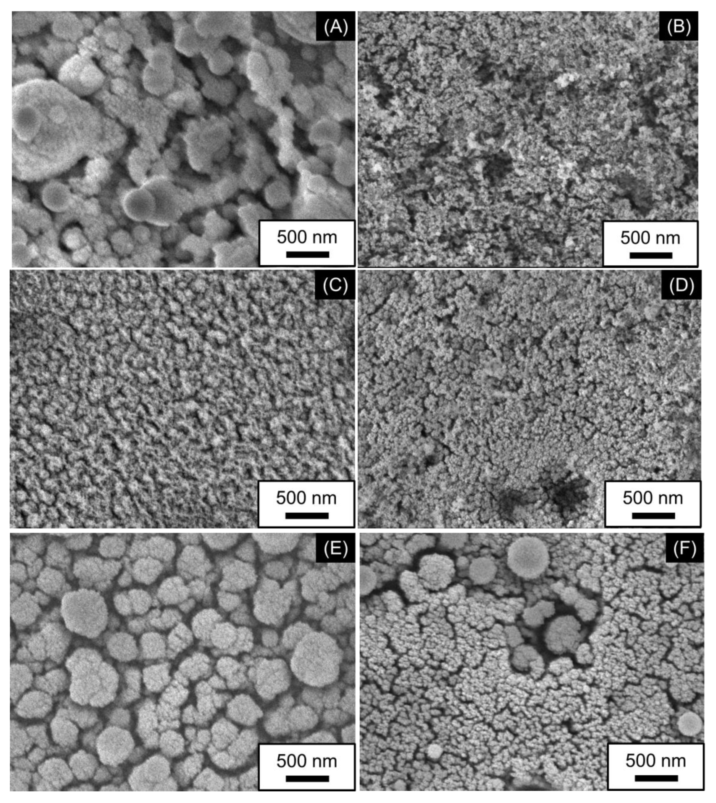
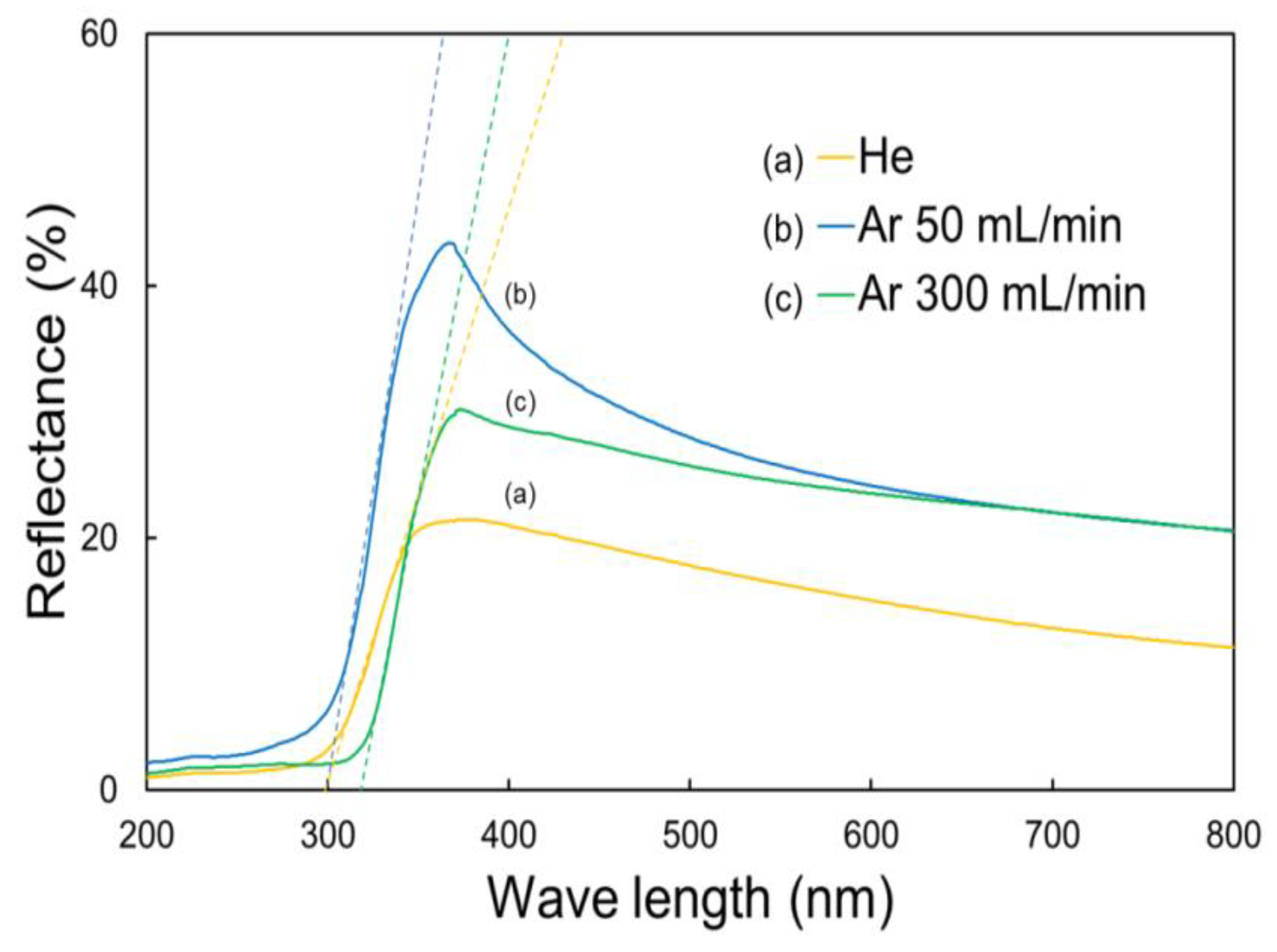
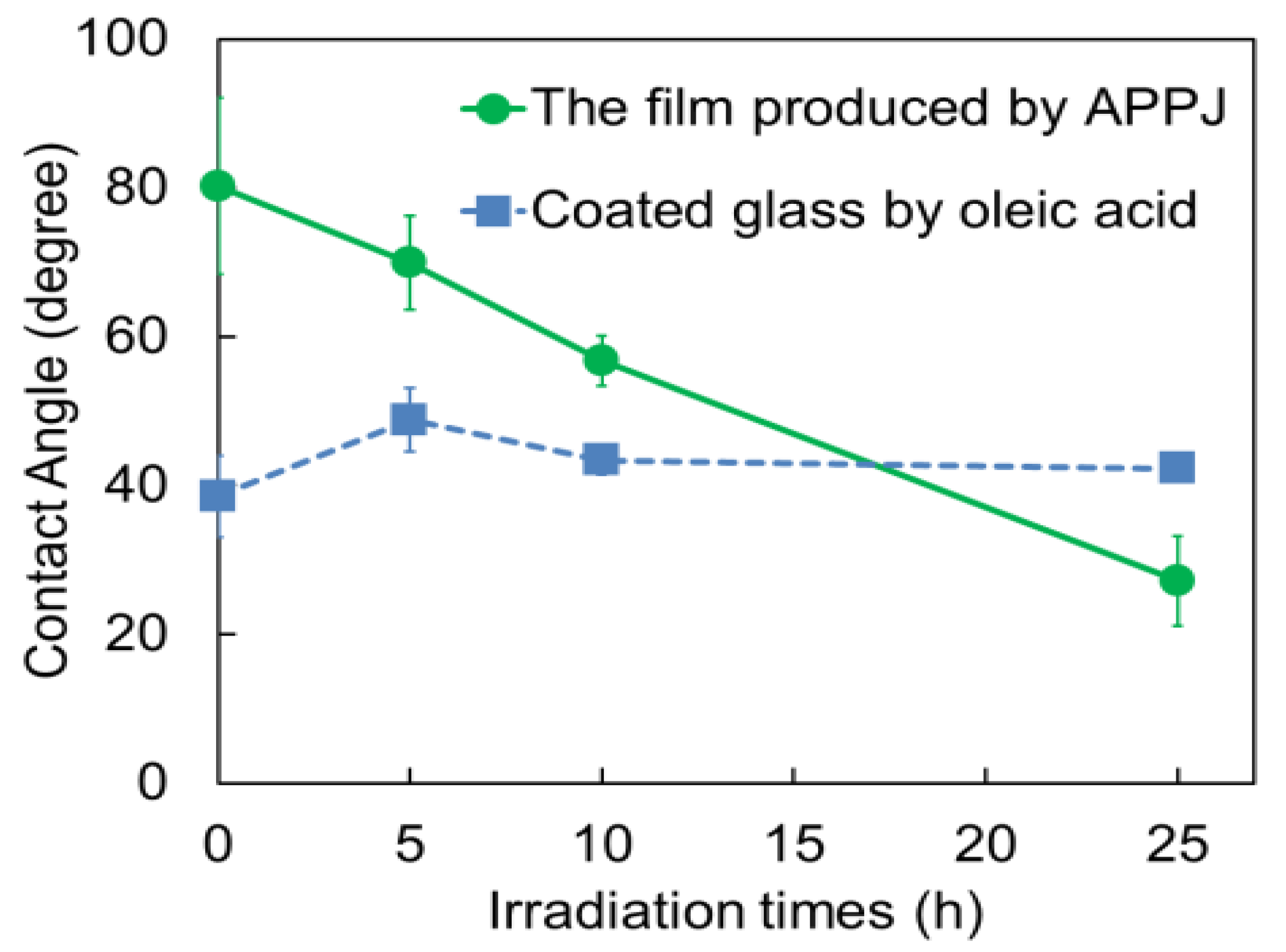
2. Results and Discussion
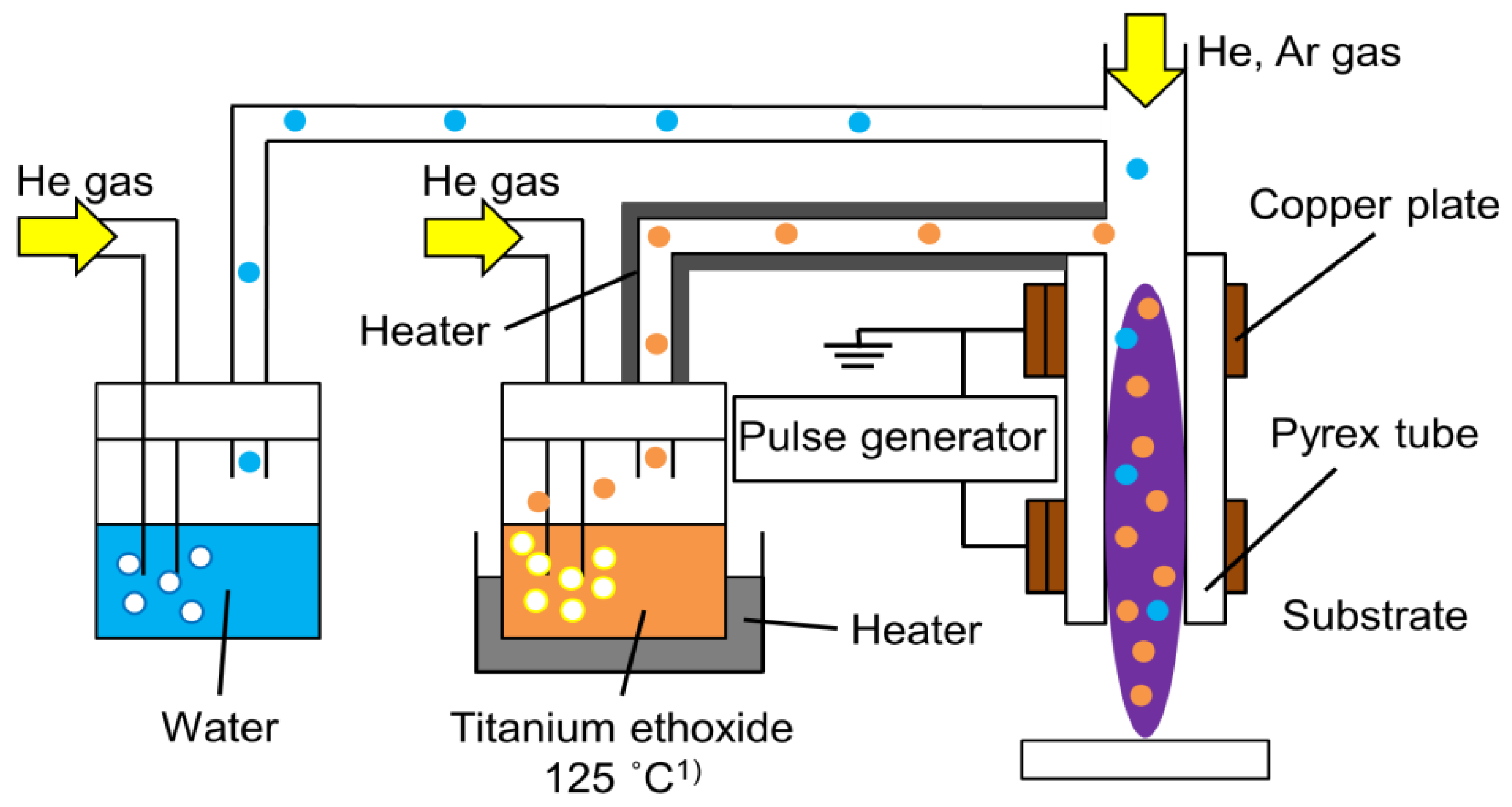
3. Experimental
3.1. Materials
3.2. Synthesis of TiO2 Thin Film
3.3. Photocatalytic Activity Test
3.4. Characterization Technique Details
4. Conclusions
Author Contributions
Funding
Institutional Review Board Statement
Informed Consent Statement
Data Availability Statement
Conflicts of Interest
References
- Linsebigler, A.L.; Lu, G.; Yates, J.T., Jr. Photocatalysis on TiO2 Surfaces: Principles, Mechanisms, and Selected Results. Chem. Rev. 1995, 95, 735–758. [Google Scholar] [CrossRef]
- Fan, Q.; McQuillin, B.; Ray, A.K.; Turner, M.L.; Seddon, A.B. High density, non-porous anatase titania thin films for device applications. J. Phys. D Appl. Phys. 2000, 3, 2683–2686. [Google Scholar] [CrossRef]
- Hashimoto, K.; Irie, H.; Fujishima, A. TiO2 photocatalysis: A historical overview and future prospects. Jpn. J. Appl. Phys. 2005, 44, 8269. [Google Scholar] [CrossRef]
- Hunge, Y.M.; Yadav, A.A.; Khan, S.; Takagi, K.; Suzuki, N.; Teshima, K.; Terashima, C.; Fujishima, A. Photocatalytic degradation of bisphenol A using titanium dioxide@nanodiamond composites under UV light illumination. J. Colloid Interface Sci. 2021, 582, 1058–1066. [Google Scholar] [CrossRef] [PubMed]
- Schutze, A.; Jeong, J.Y.; Babayan, S.E.; Park, J.; Selwyn, G.S.; Hicks, R.F. The atmospheric-pressure plasma jet: A review and comparison to other plasma sources. IEEE Trans. Plasma Sci. 1998, 26, 1685–1693. [Google Scholar] [CrossRef] [Green Version]
- Mariotti, D.; Belmonte, T.; Benedikt, J.; Velusamy, T.; Jain, G.; Švrček, V. Low-Temperature Atmospheric Pressure Plasma Processes for “Green” Third Generation Photovoltaics. Plasma Process. Polym. 2016, 13, 70–90. [Google Scholar] [CrossRef] [Green Version]
- Tendero, C.; Tixier, C.; Tristant, P.; Desmaison, J.; Leprince, P. Atmospheric pressure plasmas: A review. Spectrochim. Acta B 2006, 61, 2–30. [Google Scholar] [CrossRef]
- Dong, S.; Watanabe, M.; Dauskardt, R.H. Conductive Transparent TiNx/TiO2 Hybrid Films Deposited on Plastics in Air Using Atmospheric Plasma Processing. Adv. Funct. Mater. 2014, 24, 3075–3081. [Google Scholar] [CrossRef]
- Chou, W.C.; Liu, W.J. Study of dye sensitized solar cell application of TiO2 films by atmospheric pressure plasma deposition method. In Proceedings of the International Conference on Electronics Packaging (ICEP), Sapporo, Japan, 20–22 April 2016. [Google Scholar]
- Gazal, Y.; Dublanche-Tixier, C.; Chazelas, C.; Colas, M.; Carles, P.; Tristant, P. Multi-structural TiO2 film synthesized by an atmospheric pressure plasma-enhanced chemical vapor deposition microwave torch. Thin Solid Films 2016, 600, 43–52. [Google Scholar] [CrossRef]
- Liu, G.; Yan, X.; Chen, Z.; Wang, X.; Wang, L.; Lu, G.Q.; Cheng, H.M. Synthesis of rutile-anatase core-shell structured TiO2 for photocatalysis. J. Mater. Chem. 2009, 19, 6590–6596. [Google Scholar] [CrossRef]
- Wang, Y.; Yuan, Q.; Yin, G.; Zhang, Y.; Zhang, Y.; Li, Y.; Li, J.; Wang, T.; Ma, S. Synthesis of Mixed-Phase TiO2 Nanopowders Using Atmospheric Pressure Plasma Jet Driven by Dual-Frequency Power Sources. Plasma Chem. Plasma Process. 2016, 36, 1471–1484. [Google Scholar] [CrossRef]
- Chang, H.; Hsu, C.M.; Kao, P.K.; Yang, Y.J.; Hsu, C.C.; Cheng, I.C.; Chen, J.Z. Dye-sensitized solar cells with nanoporous TiO2 photoanodes sintered by N2 and air atmospheric pressure plasma jets with/without air-quenching. J. Power Source 2014, 251, 215–221. [Google Scholar] [CrossRef]
- Suzuki, N.; Terashima, C.; Nakata, K.; Katsumata, K.; Fujishima, A. Synthesis of a mesoporous titania thin film with a pseudo-single-crystal framework by liquid-phase epitaxial growth, and enhancement of photocatalytic activity. RSC Adv. 2020, 10, 40658–40662. [Google Scholar] [CrossRef]
- Yasuda, H.; Hirotsu, T. Critical Evaluation of Conditions of Plasma Polymerization. J. Polym. Sci. Polym. Chem. Ed. 1978, 16, 743–759. [Google Scholar] [CrossRef]
- Fakhouri, H.; Salem, D.B.; Carton, O.; Pulpytel, J.; Khonsari, F.A. Highly efficient photocatalytic TiO2 coatings deposited by open air atmospheric pressure plasma jet with aerosolized TTIP precursor. J. Phys. D Appl. Phys. 2014, 47, 265301. [Google Scholar] [CrossRef]
- Zhou, Y.; Zhu, Q.; Tian, J.; Jiang, F. TiO2 Nanobelt@Co9S8 Composites as Promising Anode Materials for Lithium and Sodium Ion Batteries. Nanomaterials 2017, 7, 252. [Google Scholar] [CrossRef]
- Borowicz, P.; Latek, M.; Rzodkiewicz, W.; Łaszcz, A.; Czerwinski, A.; Ratajczak, J. Deep-ultraviolet Raman investigation of silicon oxide: Thin film on silicon substrate versus bulk material. Adv. Nat. Sci. Nanosci. Nanotechnol. 2012, 3, 045003. [Google Scholar] [CrossRef]
- Jokisaari, J.R.; Bayerl, D.; Zhang, K.; Xie, L.; Nie, Y.; Schlom, D.G.; Kioupakis, E.; Graham, G.W.; Pan, X. Polarization-Dependent Raman Spectroscopy of Epitaxial TiO2(B) Thin Films. Chem. Mater. 2015, 27, 7896–7902. [Google Scholar] [CrossRef]
- Hunge, Y.M.; Yadav, A.A.; Dhodamani, A.G.; Suzuki, N.; Terashima, C.; Fujishima, A.; Mathe, V.L. Enhanced photocatalytic performance of ultrasound treated GO/TiO2 composite for photocatalytic degradation of salicylic acid under sunlight illumination. Ultrason. Sonochem. 2020, 61, 104849. [Google Scholar] [CrossRef]
- Hernandez-Rodriguez, E.; Marquez-Herrera, A.; Zaleta-Alejandre, E.; Melendez-Lira, M.; Cruz, W.D.; Zapata-Torres, M. Effect of electrode type in the resistive switching behavior of TiO2 thin films. J. Phys. D Appl. Phys. 2013, 46, 045103. [Google Scholar] [CrossRef]
- Vijaya, G.; Singh, M.M.; Krupashankara, M.S.; Kulkarni, R.S. Effect of Argon Gas Flow Rate on the Optical and Mechanical Properties of Sputtered Tungsten Thin Film Coatings. IOP Conf. Ser. Mater. Sci. Eng. 2016, 149, 012075. [Google Scholar] [CrossRef] [Green Version]
- Zurek, J.; Michalik, M.; Schmitz, F.; Kern, T.U.; Singheiser, L.; Quadakkers, W.J. The Effect of Water-Vapor Content and Gas Flow Rate on the Oxidation Mechanism of a 10% Cr-Ferritic Steel in Ar-H2O Mixtures. Oxid. Met. 2005, 63, 401–422. [Google Scholar] [CrossRef]
- Rebrov, A.K.; Emelyanov, A.A.; Plotnikov, M.Y.; Timoshenko, N.I.; Terekhov, V.V.; Yudin, I.B. Effect of the gas mixture flow rate on the process of diamond synthesis from a high-velocity microwave plasma. J. Appl. Mech. Tech. Phys. 2020, 61, 819–827. [Google Scholar] [CrossRef]
- Jena, S.; Tokas, R.B.; Misal, J.S.; Rao, K.D.; Udupa, D.V.; Thakur, S.; Sahoo, N.K. Effect of O2/Ar gas flow ratio on the optical properties and mechanical stress of sputtered HfO2 thin films. Thin Solid Films 2015, 592, 135–142. [Google Scholar] [CrossRef]
- Adachi, T.; Latthe, S.S.; Gosavi, S.W.; Roy, N.; Suzuki, N.; Ikari, H.; Kato, K.; Katsumata, K.; Nakata, K.; Furudate, M.; et al. Photocatalytic, superhydrophilic, self-cleaning TiO2 coating on cheap, light-weight, flexible polycarbonate substrates. Appl. Surf. Sci. 2018, 458, 917–923. [Google Scholar] [CrossRef]


| Mass (%) | ||||
|---|---|---|---|---|
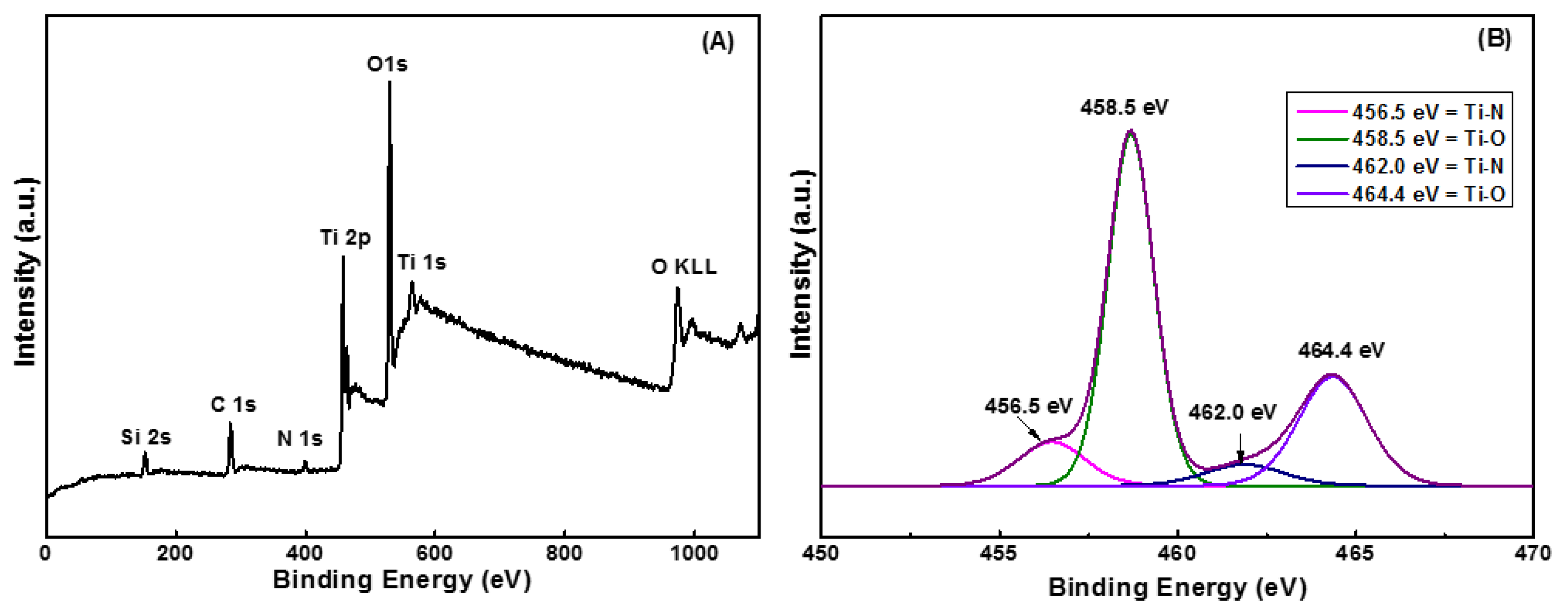
| Ti (2p) | O (1s) | C (1s) | N (1s) | |
| Ar 50 mL/min (5 mm) | 37.18 | 42.41 | 17.63 | 2.78 |
| Ar 50 mL/min (1 mm) | 39.02 | 44.47 | 14.58 | 1.93 |
| Ar 300 mL/min (5 mm) | 36.72 | 43.29 | 17.65 | 2.34 |
| Ar 300 mL/min (1 mm) | 43.91 | 38.10 | 16.58 | 1.40 |
| Mass (%) | ||||
|---|---|---|---|---|
| Ti-N (456 eV) | Ti-O (459 eV) | Ti-N (462 eV) | Ti-O (464 eV) | |
| Ar 50 mL/min (5 mm) | 22.97 | 45.92 | 16.34 | 14.77 |
| Ar 300 mL/min (5 mm) | 10.29 | 57.30 | 5.88 | 26.53 |
Publisher’s Note: MDPI stays neutral with regard to jurisdictional claims in published maps and institutional affiliations. |
© 2021 by the authors. Licensee MDPI, Basel, Switzerland. This article is an open access article distributed under the terms and conditions of the Creative Commons Attribution (CC BY) license (http://creativecommons.org/licenses/by/4.0/).
Share and Cite
Gosavi, S.; Tabei, R.; Roy, N.; Latthe, S.S.; Hunge, Y.M.; Suzuki, N.; Kondo, T.; Yuasa, M.; Teshima, K.; Fujishima, A.; et al. Low Temperature Deposition of TiO2 Thin Films through Atmospheric Pressure Plasma Jet Processing. Catalysts 2021, 11, 91. https://0-doi-org.brum.beds.ac.uk/10.3390/catal11010091
Gosavi S, Tabei R, Roy N, Latthe SS, Hunge YM, Suzuki N, Kondo T, Yuasa M, Teshima K, Fujishima A, et al. Low Temperature Deposition of TiO2 Thin Films through Atmospheric Pressure Plasma Jet Processing. Catalysts. 2021; 11(1):91. https://0-doi-org.brum.beds.ac.uk/10.3390/catal11010091
Chicago/Turabian StyleGosavi, Suresh, Rena Tabei, Nitish Roy, Sanjay S. Latthe, Yuvaraj M. Hunge, Norihiro Suzuki, Takeshi Kondo, Makoto Yuasa, Katsuya Teshima, Akira Fujishima, and et al. 2021. "Low Temperature Deposition of TiO2 Thin Films through Atmospheric Pressure Plasma Jet Processing" Catalysts 11, no. 1: 91. https://0-doi-org.brum.beds.ac.uk/10.3390/catal11010091