Next Article in Journal
Nanocomposite Cathode Catalysts Containing Platinum Deposited on Carbon Nanotubes Modified by O, N, and P Atoms
Next Article in Special Issue
Synthesis of Indoles via Intermolecular and Intramolecular Cyclization by Using Palladium-Based Catalysts
Previous Article in Journal
rGO Functionalized ZnO–TiO2 Core-Shell Flower-Like Architectures for Visible Light Photocatalysis
Previous Article in Special Issue
Fe3 Cluster Anchored on the C2N Monolayer for Efficient Electrochemical Nitrogen Fixation
 
 
Comment published on 26 September 2021, see Catalysts 2021, 11(10), 1154.
Article

Mayenite-Based Electride C12A7e: A Reactivity and Stability Study

1
hte GmbH, Kurpfalzring 104, 69123 Heidelberg, Germany
2
Leibniz Institute for Catalysis (LIKAT Rostock), Albert-Einstein-Straße 29a, 18059 Rostock, Germany
3
Felix-Bloch-Institut für Festkörperphysik, Leipzig University, Linnéstraße 5, 04103 Leipzig, Germany
4
BASF SE, Carl-Bosch-Straße 38, 67056 Ludwigshafen am Rhein, Germany
5
Institute of Chemistry, TU Berlin, Straße des 17. Juni 135, 10623 Berlin, Germany
6
Institute of Chemical Technology, Leipzig University, Linnéstraße 3, 04103 Leipzig, Germany
7
Institute of Inorganic Chemistry, Leipzig University, Johannisallee 29, 04103 Leipzig, Germany
*
Author to whom correspondence should be addressed.
New address: Institute for Chemical Technology and Polymer Chemistry (ITCP) Engesserstraße 20, 76131 Karlsruhe, Germany.
New address: Institute of Catalysis Research and Technology (IKFT), Karlsruhe Institute of Technology (KIT), Hermann-von-Helmholtz-Platz 1, 76344 Eggenstein-Leopoldshafen, Germany.
Submission received: 19 February 2021 / Revised: 2 March 2021 / Accepted: 3 March 2021 / Published: 5 March 2021
(This article belongs to the Special Issue Transition Metal Catalysis)

Abstract

:
Ru supported on mayenite electride, [Ca24Al28O64]4+(e)4 a calcium aluminum oxide denoted as C12A7e, are described in the literature as highly active catalysts for ammonia synthesis, especially under conditions of low absolute pressure. In this study, we investigated the application of recently reported plasma arc melting synthesized C12A7e (aluminum solid reductant) as supports of Ru/C12A7e catalysts in ammonia synthesis up to pressures of 7.6 MPa. Together with the plasma-arc-melting-based catalyst support, we investigated a similar plasma-synthesized C12A7e (graphite solid reductant) and a vacuum-sintering-based C12A7e. Complementary to the catalytic tests, we applied 2H solid-state NMR spectroscopy, DRUVVis-spectroscopy, thermal analysis and PXRD to study and characterize the reactivity of different plasma-synthesized and vacuum-sintered C12A7e towards H2/D2 and H2O. The catalysts showed an immediate deactivation at pressures > 1 MPa, which can be explained by irreversible hydride formation at higher pressures, as revealed by reactivity tests of C12A7e towards H2/D2. The direct formation of C12A7:D from C12A7e is proven. It can be concluded that the application of Ru/C12A7e catalysts at the industrial scale has limited prospects due to irreversible hydride formation at relevant pressures > 1 MPa. Furthermore, we report an in-depth study relating to structural changes in the material in the presence of H2O.

Graphical Abstract

1. Introduction

Ammonia synthesis is one of the major processes in the chemical industry and the established Haber–Bosch process is already more than 100 years old [1,2,3]. For industrial applications, Fe-based catalysts are mainly used, which trace back also to the early studies of Mittasch [4]. In industrial conditions, this process is typically carried out in a temperature range of 673 to 773 K and pressures of above 15 MPa [5]. Another catalyst family that has also found industrial use is Ru as an active metal supported on carbon with promoters: these types of catalyst can be applied and are of general interest as they are more active compared to Fe-based catalysts at lower temperatures, therefore offering a process-advantage [6]. For Fe-based catalysts, N2 dissociation is considered as the rate-determining step of the reaction happening on seven coordinated Fe-sites [7,8,9]. For the Ru-based catalyst, a similar structure sensitivity is reported, and step sites of the Ru surface are considered as favorable sites while the N2 dissociation is also assumed as a rate-determining step [10,11,12,13,14]. However, Ru-based ammonia synthesis catalysts typically suffer from poisoning by H2 limiting the performance at higher pressures, which is explained by the competitive adsorption of N2 and H2 on Ru [6,15,16].
Overcoming the aforementioned challenges, and accordingly improving the potentials of Ru-based catalysts, the group of Hosono reported that Ru supported on a novel support material, namely, mayenite electrides—[Ca24Al28O64]4+(e)4—in combination, results in catalysts that are described as highly active for ammonia synthesis [17,18]. The electride support material [Ca24Al28O64]4+(e)4, denoted as C12A7e, was reported to be stable up to 673 K under atmospheric conditions. C12A7e is based on the mayenite structure, as first reported by the group of Hosono [19,20,21]. Mayenite is a calcium aluminum oxide, which can be described by a positively charged framework of 12 cages [Ca24Al28O64]4+ with anions distributed inside the cages compensating for the charge, in case of the oxygen mayenite [Ca24Al28O64]4+(O2−)2, denoted as C12A7 [22,23,24,25,26,27]. For the mayenite structure, several anionic species are reported, e.g., OH [28,29,30], H [19,29,31,32,33,34], N3− [35], NH2 [35,36] and NH2− [37]. Mayenite-based electrides [Ca24Al28O64]4+(2 × δ)e(2 − δ)O2− show interesting properties depending on the electron concentration Ne. The material can, in fact, be an insulator (colorless, δ = 0, Ne = 0 cm−3), semi-conductor (green color, δ < 1, Ne < 1 × 1021 cm−3) or metallic conductor (very dark or black, δ > 1, Ne > 1 × 1021 cm−3) with a maximum possible Ne = 2.3 × 1021 cm−3 [20,21,22,38]. The metallic conducting C12A7e exhibits a work function of 2.4 eV [39].
Due to the “promoting” properties of the electride support, the group of Hosono reported that the rate-determining step of ammonia synthesis over Ru/C12A7e was not the dissociation of N2, but rather the subsequent formation of N-Hx species. At the same time, it was observed that the nature of the reaction mechanism depends on the electron concentration of the mayenite electride support [31,40]. The group concluded that a metallic conducting electride is required for superior activity, and its action is explained as an “electronic promoter” for Ru, and that the H2 poisoning could be overcome by the reversible incorporation and release of H into the electride structure [17,18,31,40]. The reported turnover frequency (TOF) of 0.98 s−1 for this catalyst is more than one order of magnitude higher than that of comparable, conventional Ru-Ba/activated carbon or Ru-Cs/MgO catalysts [18]. However, they reported the catalytic test results only for pressures up to 1.3 MPa [17,18], which is considerably lower than industrially relevant conditions [5]. A recent work of Kammert et al. investigated the role of hydrogen for this catalyst in detail with in situ neutron-scattering techniques and found that the suggested reversible incorporation and release of H in the mayenite structure does not play a major role in the mechanism in contrast to the findings of the group of Hosono [17,32]. They further applied steady-state isotopic transient kinetic analysis with isotopically labelled nitrogen to determine the number of reactive nitrogen intermediates on the catalyst surface, reporting that the promoting effect of the electride support enables much higher coverages of Ru by adsorbates compared to use of the oxygen mayenite support (coverages 84% vs. 15%, respectively) [32]. Thus, the promoting properties of the electride are crucial for the enhanced performance of the material to prevent poisoning by H2 and not a reversible uptake and release of hydrogen in the mayenite structure.
The synthesis of metallic conducting C12A7e was initially achieved by the reaction of C12A7 with Ca at 973 K for 240 h in evacuated silica tubes [21]. Later, other solid-reductants or synthesis procedures were applied, as reviewed by Kim et al., Salasin et al., or Khan et al. [20,22,38]. Potential scalable synthesis procedures of powdered C12A7e, readily applicable as catalyst supports with high electron concentrations, were only recently reported. This includes stoichiometric synthesis from CaO, Al2O3, Al at 1373 K for 8 h under Ar [41], or plasma-arc-melting synthesis with the addition of solid reductants like Al or graphite, which yielded C12A7e within less than 1 min [42]. The synthesis of the stoichiometric hydride C12A7:H is possible starting from C12A7 by reaction with CaH2 or TiH2 at 1073 K for > 120 h in sealed silica tubes [29,34]. Non-stoichiometric hydrides, still containing O2−, OH or e, were reported for the reaction of C12A7 or C12A7e with gaseous H2 [19,29,31,32,33,34]. The hydrogen uptake of Ru/C12A7e and C12A7e by temperature-programmed absorption, as studied by Kitano et al., showed that, for the Ru-containing sample, the uptake occurs at lower temperatures, with a maximum of ca. 100 K lower at about 750 K, compared to the pure C12A7e [31]. It should be noted that, in temperature-programmed desorption experiments, it was found that H2 was also released at lower temperatures for the Ru/C12A7e sample compared to C12A7e and at lower temperatures than the absorption [31]. The mayenite materials are typically hygroscopic, while the reaction of C12A7e with H2O was only recently reported by Jiang et al., showing the formation of Al2Ca4(OH)12 and slight amounts of Al(OH)3 [43]. Thus, potential stability issues of the Ru/C12A7e catalyst towards H2O were not frequently reported. To the best of our knowledge, the only records are a review and a study on a new potential electride support for ammonia synthesis Y5Si3—but no detailed information on the nature of the water instability of the mayenite electride materials is provided in these publications [17,44].
To date, the studies of the catalytic performance of Ru/C12A7e reported in the literature were only conducted under model laboratory conditions with low pressures of less than 1.3 MPa [17,18,31,32,40]. Studies under relevant industrial operation conditions, especially higher pressures, of the catalyst in ammonia synthesis, are desirable to evaluate its potential in industrial applications. In the present study, we first report the application of Ru/C12A7e catalysts under ammonia synthesis conditions close to atmospheric, and at elevated pressures, to investigate all industrial-relevant operation conditions. The mayenite electride support materials were obtained by plasma-arc melting of mayenite starting materials, as reported here [42]. We further investigated the C12A7e support material through reactivity studies towards H2/D2 under atmospheric pressure and higher pressure to better understand the issues concerning the catalyst stability and potential deactivation mechanism by hydride formation. The studies are complemented by hydrothermal reactivity experiments of C12A7 and C12A7e to assess the stability towards H2O.

2. Results and Discussion

In this study, we investigated the activity, reactivity, and stability of different C12A7e samples prepared by two different synthetic routes. The relevant samples are summarized in Table 1 and can be divided into four groups: 1. Plasma-synthesized C12A7 and C12A7e samples (a)–(d), 2. Vacuum-sintering-based sample (e), 3. Ru supported on C12A7 and C12A7e (f)–(i) based on samples of the plasma treatment route (I), and 4. hydride (j) and deuteride (k) of the vacuum-sintering-based C12A7e. The prepared C12A7e samples (c)–(e) are of dark green color, which can be attributed to semiconductingclose to metallicconducting C12A7e samples according to the literature and a previous study on plasma-treatment-based C12A7e (electron concentration Ne from approximately 0.1 to 1.2 ∙ 1021 cm−3) [20,21,22,38,42]. The plasma-treatment-based samples (a) and (d) are used for reactivity and stability experiments under hydrothermal conditions. (d) and (e) were tested regarding their reactivity towards hydrogen and possible hydride/deuteride formation. Catalytic activity tests were performed for the plasma-based samples (g) and (h), while sample (i) was used to investigate whether the electride properties are still present after Ru deposition. The samples (j) and (k) were obtained from high-pressure hydrogenation experiments in the DSC or autoclave.
In the following sections, we will first discuss the deposition of Ru on plasma-synthesized C12A7e samples, followed by the catalytic testing of those materials in ammonia synthesis. This is complemented by reactivity and stability studies of the electride materials concerning hydrogenation and hydrothermal conditions.

2.1. Ruthenium Deposition

The deposition of Ru was carried out as adapted from the literature procedure of Kitano et al. [18]. Four different Ru-loaded samples (f)–(i), based on C12A7 and C12A7e prepared by plasma synthesis (a)–(d), are discussed in this work. For catalytic tests, the Al-based samples (g) and (h) were used, while the pure C12A7 (f) and the graphite-based electride (g) were used to test if the material still qualified as an electride after Ru deposition. The quantitative Ru deposition on the samples was confirmed by XRF analysis. After Ru deposition, the color changed from colorless to gray in case of samples (a) and (f), where the pure oxygen mayenite C12A7 was present. For samples with Ru deposited on C12A7e, the color changed to dark gray. The obtained powders of samples (f) Ru/C12A7 and (i) Ru/C12A7e (3C) are shown in Figure 1, illustrating the color difference between the respective supports. Both samples were also studied by STA analysis in synthetic air, with the DSC and TG curves shown in Figure 1. For both samples, a mass loss can be observed starting at about 500 K, while the mass loss is greater for the Ru/C12A7 sample compared to the C12A7e-based one. We expect this mass loss to be caused by either not fully decomposed Ru3(CO)12 precursors or by the release of adsorbed H2O, or both. At about 900 K, the TG curves for the two samples differ, as the Ru/C12A7e sample shows a mass uptake with a maximum of about 1150 K. This mass uptake can be assigned to the transformation of C12A7e to C12A7. The maximum and the temperature region are well in line with previous studies on plasma-treatment-based C12A7e and the literature values [42,45,46,47], indicating that the C12A7e is still present after Ru deposition. In the DSC curves, no clear signal for both samples can be observed.
To further investigate the presence of C12A7e after Ru deposition, the samples (f) Ru/C12A7 and (i) Ru/C12A7e (3C) were characterized by DRUVVis and EPR spectroscopy, as shown in Figure 2. The DRUVVis spectra are shown together with the spectra of the initial C12A7e sample (d). One cannot observe the typical peak at around 2.83 eV for C12A7e for the Ru-containing sample (i) [21]. However, it should be noted that the Kubelka–Munk intensity for the Ru/C12A7e sample is significantly higher compared to the Ru/C12A7-based material. Based on the DRUVVis results, we cannot analyze the electron concentration of the Ru-containing samples and, also from DRUVVis, an unambiguous presence of C12A7e after Ru deposition cannot be concluded.
The EPR spectra of the samples (f) and (i) are shown, together with the spectra of the pure C12A7 sample (a). The Ru/C12A7e exhibits the typical EPR signal for the semiconducting electride at 339.5 mT. The normalized intensity IN of the signal is 410, which is significantly lower compared to the range from 2500 to 4825, as reported for pure C12A7e (3C) samples obtained from plasma treatment [42]. For sample (f) Ru/C12A7, a different signal at lower magnetic field strength of 334.5 mT is observed, which cannot be attributed to C12A7e.
Based on the results obtained from STA, DRUVVis and EPR analysis, it can be concluded that after Ru deposition on the plasma-synthesized C12A7e samples, the material still corresponds to the semiconducting C12A7e. However, the electron concentration seems to have decreased, as indicated by the IN of the EPR spectra and the absence of a clear absorption peak within the DRUVVis experiments. PXRD (Figure S2) of the samples (g) and (i) after Ru deposition do not show changes compared to the used C12A7 and C12A7e samples, while no distinct Ru reflections could be observed, indicating X-ray-amorphous deposition of the Ru on the support material, which could be confirmed as shown in the TEM image in Figure S1.

2.2. Reactivity Studies of C12A7 and C12A7e

2.2.1. Catalytic Studies of Ru/C12A7e

The catalytic activity of the two Ru/C12A7e catalysts (g) and (h) was tested in ammonia synthesis. Both catalysts are based on plasma-synthesized C12A7e with Al used as a solid reductant. Sample (h) exhibited a higher electron concentration compared to (g), as indicated by the color difference, while sample (g) is a semiconducting material, and (h) is expected to be semiconducting close to metallic conduction, as reported in the literature [42,45,46,47]. The two samples were tested under different reaction conditions of ammonia synthesis, denoted as segments, with varied reaction temperatures and pressures, as listed in Table 2. The tested temperatures ranged from 593 to 673 K, and the pressure from 0.1 up to 7.6 MPa. The NH3 formation rate for all testing conditions of the two catalysts is shown in Figure 3.
For segments with reaction pressures of 0.1 Mpa, both samples are highly active catalysts in ammonia synthesis. However, their specific activity appears to be different. While the sample with lower electron concentration (g) Ru/C12A7e (5Al) has its maximum activity at 673 K, with an NH3 formation rate of 1066 µmol h−1 g−1, the catalyst (h) exhibits its highest activity at 633 K, with 2493 µmol h−1 g−1. This rate is well in agreement with the value reported by Kitano et al. of 2730 µmol h−1 g−1 for an Ru/C12A7e catalyst with a similar loading of 1.2 wt.% Ru [31]. In the first reported application of the material for NH3 synthesis, by the group of Hosono et al., they reported a rate of 2760 µmol ∙ h−1 ∙ g−1 for a 1.2 wt.% Ru/C12A7e sample at 673 K, which is a slightly higher activity than the Ru/C12A7e (20Al) sample discussed here [18]. Comparing the Ru/C12A7e (5Al) and (20Al) we can observe differences in their activity, which we attribute to the different electron concentration of the material, based on the color appearance of the precursor C12A7e. This observation is in line with the previous studies of Kanbara et al., who showed the dependence of the activity of Ru/C12A7e catalysts for NH3 synthesis on the electron concentration of the C12A7e support [40].
A remarkably different behavior of the Ru/C12A7e (5Al) and (20Al) samples compared to studies of the group of Hosono can be observed for tests at higher pressures. In the available reports, test results of the materials were only reported for pressures up to 1.3 Mpa at 673 K [17,18]. As soon as Ru/C12A7e (5Al) and (20Al) were tested at 633 K and higher pressures of >1.0 Mpa, an immediate decrease in the NH3 formation is observed, as shown in Figure 3, for both catalysts. Kitano et al. reported an increase in activity by increasing the pressure from 0.1 to 1.0 Mpa at 673 K [18]. From the catalytic testing results, we assume that the immediate deactivation is caused by the transformation of an mayenite electride to a mayenite-based hydride phase (C12A7:H), where, instead of electrons, the cages are occupied with H ions. This behavior contrasts with the studies of the group of Hosono at low pressures. The group investigated the H2 uptake of the catalyst material by reaction with H2 (H2(75 kPa), Ar(25 kPa), 633 K) and during reaction conditions (H2(75 kPa), Ar(25 kPa), 633 K), which suggested that only 1% of the electrons react with hydrogen to H under reaction conditions, while under H2/Ar conditions 50% of the electrons are exchanged after 40 h [31]. With H2 uptake experiments and kinetic studies, they concluded that H2 is reversibly incorporated into the cages of the mayenite structure and prevents the poisoning of Ru with H2 under these reaction conditions, concluding that the Ru/C12A7e catalyst is stable for NH3 synthesis [17,18,31]. Kammert et al. studied the H2 and D2 uptake of Ru/C12A7e by in situ neutron diffraction and steady-state isotopic transient kinetic analysis. They concluded that H2 and D2 in the cages are not likely to participate in the reaction mechanism, as only a minor exchange is observed, and a rather high possible coverage of adsorbed species on Ru is the reason for the poisoning resistance and enhanced activity [32]. However, their experiments were not carried out at pressures higher than 0.1 Mpa. In combination with these findings, we tend to explain the immediate loss of activity upon higher pressures as caused by the irreversible transformation of the mayenite electride into a mayenite-based hydride C12A7:H, causing a loss of the promoting properties of the electride for Ru, and thus causing an irreversible H2 poisoning in the reaction. Based on these findings, we conclude that, despite Ru/C12A7e showing a promising and remarkable performance at ambient pressure for ammonia synthesis, as pioneered by the group of Hosono, for application under industrial-relevant conditions of higher pressures of >1.0 Mpa, no sustained activity retention is observed. The catalyst exhibits stability issues due to bulk structural transformation, and thus the material is probably not suitable for application in the established ammonia synthesis process. To further understand the reactivity of the C12A7e support, and to obtain a better understanding of the stability issues from a materials basis, in the following sections we discuss reactivity studies on H2 and H2O.

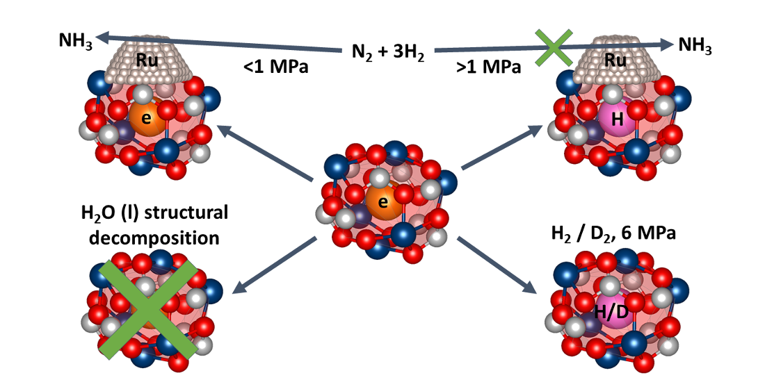
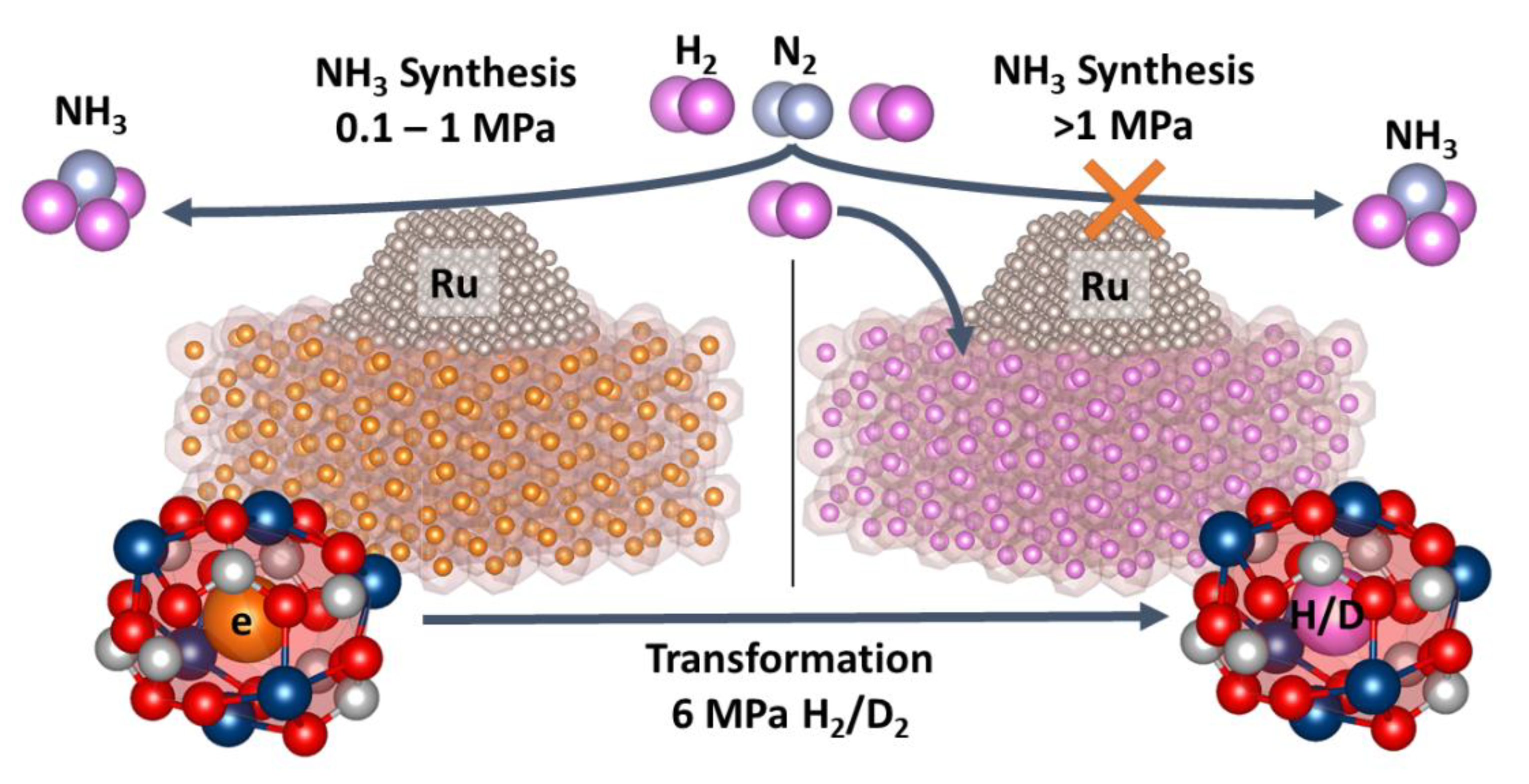
2.2.2. Reactivity towards Forming Gas and Hydrogen

The reactivity of C12A7e towards hydrogen was tested in a broad range of temperatures (i) in a tube furnace system in the presence of forming gas at 0.1 Mpa; (ii) by simultaneous thermal analysis (STA) in the presence of forming gas at 0.1 Mpa; (iii) in a DSC experiment under H2 up to 6.7 Mpa; (iv) by autoclave reaction with deuterium gas at 6 Mpa and 773 K.
Initial reactivity tests of C12A7e towards hydrogen were performed in a tube furnace system at temperatures up to 723 K and 0.1 Mpa in a 95% N2/5% H2 atmosphere. The experiments were carried out with the plasma-synthesized C12A7e (d), and the resulting pictures of the powder after treatment at different temperatures are shown in Figure 4. Starting from 623 K, one can observe a decolorization of the powder from dark green to grayish, which becomes more significant at higher temperatures. A similar experiment was carried out for the C12A7e (d) sample by heating in N2 instead of N2/H2 atmosphere, where no detectable decolorization compared to the N2/H2 atmosphere could be observed. A similar grayish color for C12A7:H is reported by Jiang et al. [33], while an onset of H2 consumption in temperature-programmed absorption studies is observed at similar temperatures by Kitano et al. [31], as indicated by the color change in Figure 4 for the present study.
The reactivity of the plasma synthesized C12A7 (a) and C12A7e (d) was further investigated by simultaneous thermal analysis (STA). STA experiments were carried out under a forming gas atmosphere (95% N2/5% H2). The results are shown in Figure 5 (left). For both samples, a mass uptake in the TG could be observed, though the uptake is larger for the C12A7e sample. The difference between both samples is pronounced in the region where the color change, as shown in Figure 4, takes place for the C12A7e sample. The DSC curves for both samples do not show any significant signals in the region from 300 to 800 K. From the TG results, we conclude that the reaction of C12A7e with H2 starts at 600 K. Thus, the STA results support the findings of the initial reactivity studies.
The samples studied in the tube furnace under N2/H2 and N2 atmosphere were characterized by DRUVVis, as shown in Figure 5 (right). For the sample which was treated in N2/H2 atmosphere, no clear absorption band of around 2.8 eV can be identified. This indicates a strong decrease in the electron concentration and loss of the electride properties. The sample treated under N2 atmosphere still exhibits the absorption band around 2.8 eV, as in the initial C12A7e; however, the intensity is decreased, and the band is not as pronounced as before. The intensity decrease indicates a reduction in the electron concentration, as reported by Matsuishi et al. [21].
Complementary to the initial reactivity tests with plasma-synthesized C12A7e (d), the reactivity towards H2 was tested for the vacuum-sintering-based C12A7e (e) sample at higher pressures. For this purpose, initial tests were carried out in a DSC experiment under H2 pressure (5.0 to 6.7 MPa, up to 700 K), while the C12A7:D sample was prepared in an autoclave synthesis (6.0 MPa, 773 K). The hydrogenation in the DSC apparatus did not show any thermal effects, similar to the results we obtained for the plasma-synthesized samples, as shown in Figure 5 (left). However, the color change from green vacuum-sintered (e) C12A7e to colorless (j) C12A7:H clearly indicates a reaction during the DSC experiment. The reaction of green vacuum-sintered C12A7e with deuterium led to a small change in the lattice parameter from a = 11.9790(2) Å for sample (e) C12A7e to a = 11.9874(1) Å for the colorless sample (k) C12A7:D (Figures S3 and S4) used in 2H solid-state NMR spectroscopy. The color change directly indicates the reaction of the C12A7e with deuterium gas, which is accompanied by the loss of the electride properties.
To clarify the presence of deuteride anions within C12A7:D, 2H NMR studies were performed. The 2H solid-state NMR spectrum of C12A7:D in Figure 6 shows a quadrupolar line shape with an isotropic chemical shift of 4.8 ppm, a quadrupolar coupling CQ of 16 kHz and an asymmetry parameter η of 0. The quadrupolar parameters indicate a covalent character of the deuteride, while the coupling strength is rather weak. The latter suggests a non-cubic symmetry around the hydride (deuteride) ion, giving rise to the quadrupolar coupling. There are indications for a minor site with a large quadrupolar coupling of 145 kHz and an isotropic chemical shift of −1 ppm, which we assign to an OD group, such as mayenite hydroxide. The observed chemical shifts compare well with the literature data [29]. Therefore, we assume the sample to be mayenite hydride (deuteride) with some minor amount of OD groups in the clathrate cages. Mayenite hydride may thus be synthesized not only by the known routes, from C12A7/C12A7e and CaH2 [34] or C12A7 and TiH2 [29], but also by direct hydrogenation of C12A7e at elevated hydrogen gas pressures.
Kammert et al. investigated the reaction of Ru/C12A7e with H2/D2 at atmospheric pressure, but showed no complete exchange of e by H [32]. They instead found that, under atmospheric pressure, the amount of H incorporated in C12A7e increases by raising the temperature from 673 to 873 K, concluding that, under reaction conditions, the electride properties are maintained, as the C12A7e does not completely react with H2 [32]. The group of Hosono proposed that H is incorporated in small amounts into the cages at the initial stages of ammonia synthesis, but the cage H ions are readily released by the following reaction: H → H0 + e [17,18]. However, our findings from the catalytic activity tests and the reactivity studies towards H2 at higher pressures support the initial assumption that the catalyst deactivation is caused by the formation of C12A7:H under ammonia synthesis conditions at higher pressures. The results from the catalytic activity tests and reactivity studies are schematically shown in Scheme 1. If ammonia synthesis is carried out at mild pressures below 1 MPa, no bulk transformation of C12A7e to C12A7:H takes place. An increase in pressure leads to the formation of bulk C12A7:H, which is accompanied by a loss of the electride properties and, thus, loss of performance in ammonia synthesis.
It can be speculated that, at low pressures, the mechanism proposed by the group of Hosono [17,18,31,40], involving a partial and dynamic exchange of hydrogen between active metal and support, leads to an activity enhancement, and follows only a partial and still-reversible exchange between mayenite electride and hydride in the upper surface layers. Once the pressure is increased and the bulk phase is transformed into the hydride phase, the beneficial promoting properties are lost. With the loss of the promoting properties, the activity of the catalyst is strongly reduced, which was also found by Kammert et al. [32] and the group of Hosono [17,18,40], with mayenite type supports with no- or low-electron concentrations.

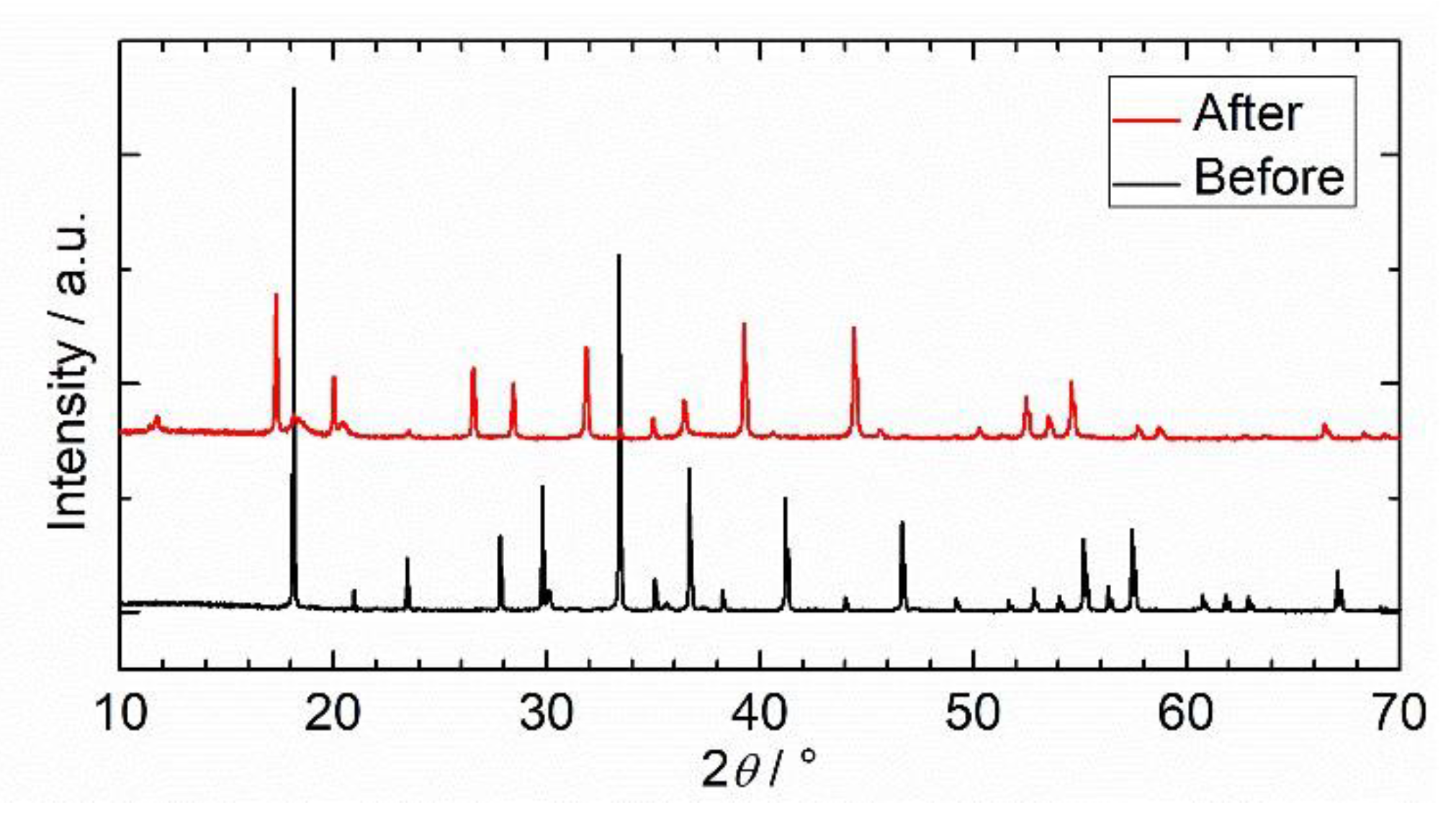
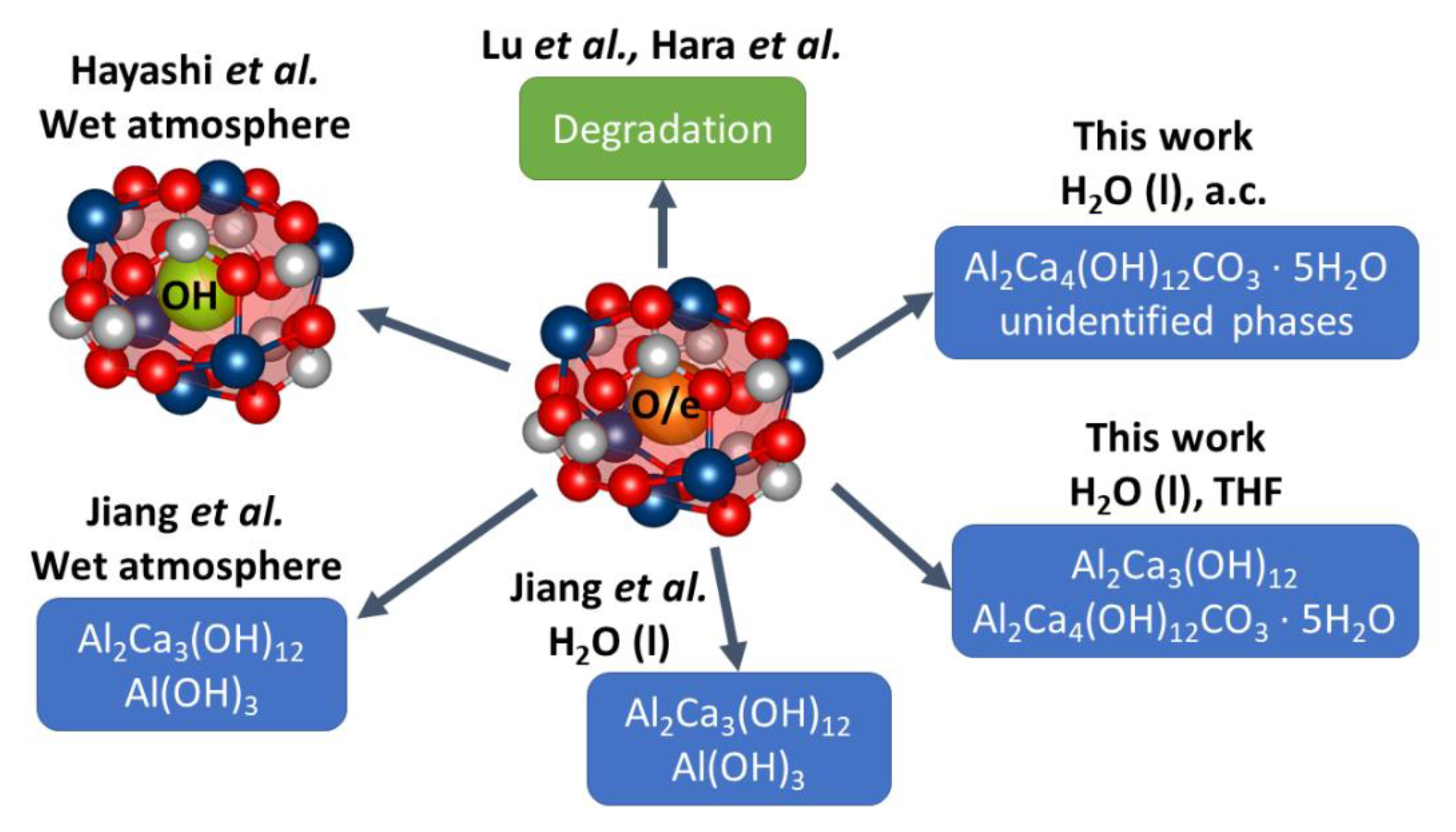
2.2.3. Hydrothermal Reactivity Tests

The hydrothermal reactivity was tested for plasma-synthesized samples (a) C12A7 and (d) C12A7e. To study the general stability of the mayenite structure, the Ar plasma-synthesized C12A7 sample (a) was exposed to H2O, as described in the experimental section. The PXRD of the resulting powder after each exposure time is shown in Figure 7. Even after only one hour of exposure to H2O at ambient conditions, we could observe structural changes in the material by the formation of a secondary phase identified as Al2Ca4(OH)12CO3 · 5H2O (orange dashed–dotted lines in Figure 7) and an unidentified phase (red dotted lines in Figure 7), accompanied by a reduction in the intensity of the C12A7 reflections. After 5 h exposure to H2O, we could observe a complete decomposition of the C12A7 structure in the PXRD patterns by the absence of C12A7 reflections, while the reflections of the unidentified phase (red dotted lines) disappear in conjunction with the occurrence of another unidentified phase. Figure 7 also shows that, when the C12A7e sample was exposed to H2O for 16 h, the color of the sample changed from dark green to gray, which indicates a loss of electride properties.
To exclude the potential influence of the atmosphere and for a more defined mixing, the stability experiments were additionally carried out under more controlled conditions. For this, the C12A7e (d) sample was suspended in tetrahydrofuran (THF) under Ar atmosphere. After suspending the material for 5 min in THF, the color of the powder was still dark green and did not change compared to the initial C12A7e sample. After the stepwise addition of H2O, the sample changed its color to white, which may indicate a decomposition of the C12A7e. In the PXRD shown in Figure 8, a complete decomposition of the C12A7 structure and the formation of mainly katoite Al2Ca3(OH)12 and some Al2Ca4(OH)12CO3 ∙ 5H2O, after reaction of the C12A7e with H2O in THF, can be observed. These results are similar to those found by Jiang et al. for hydrothermal reactivity experiments. They found Al2Ca3(OH)12 and slight amounts of Al(OH)3 by immersing the sample in H2O for 72 h or storing it under 100% relative humidity for 1 week. [43]. As we found additional aluminum calcium hydroxide phases in the experiments under ambient conditions, it could be possible that different decomposition pathways or stages of the C12A7 structure might exist under hydrothermal conditions. Hayashi et al. reported the formation of C12A7:OH upon reaction of C12A7 in a wet atmosphere without structural decomposition [28]. With respect to a potential broader application of the material in heterogeneous catalysis, the hydrothermal stability of the material might be crucial, especially for reactions where H2O is present as solvent or is produced as a reaction product. For the Ru/C12A7e catalyst, the stability issues towards water have only been reported as an aside in a study of a water-stable electride, Y5Si3 [17,44].
The results of the hydrothermal reactivity tests are summarized in Scheme 2. Upon contact with liquid H2O and 100% relative humidity, the material exhibits a structural decomposition to calcium aluminum hydroxide phases, as shown by Jiang et al. and the results in the present study [43]. Based on the literature knowledge and our study, we conclude that an initial deactivation might be caused by an exchange of the electrons inside the cage and the formation of OH while, during longer exposures to H2O, structural decomposition takes place. A more detailed investigation of the decomposition pathways of C12A7 by reaction with H2O might be carried out by in situ PXRD studies for a more holistic picture and detailed understanding of the structural decomposition pathway.

3. Materials and Methods

3.1. Synthesis

3.1.1. Synthesis of Electrides and Mayenite Hydrides

The electride samples used in this study were synthesized via two different procedures: (I) plasma synthesis and (II) solid-state reduction in a vacuum-sintering furnace.
Pathway (I), thoroughly detailed in a previous publication [42], consisted of mixing reagents to prepare the precursor, which was then calcined and mixed with a reductant prior to plasma treatment. The oxygen-mayenite precursor (C12A7) was prepared as reported earlier by mixing 56.91 g of Disperal P2 with 43.65 g of CaO and 150 mL of deionized H2O in a ball mill. The three reagents were mixed at 600 rpm four consecutive times, with alternating directions of rotation, each for 10 min and with a 5 min break in between. The obtained paste was calcined for 8 h at 1373 K with 10 K ∙ min−1 in a muffle furnace and a constant, clean dry-air flow. After the calcination step, the product was ground and characterized by powder X-ray diffraction (PXRD). For batches containing krotite (CA) and tricalcium aluminate (C3A) as the secondary phase, the product was calcined again to complete the reaction. The obtained C12A7 was mixed with a solid reductant and pressed into 13 mm pellets (about 0.5 g) with 10 t using a motorized pellet press. As solid reductants, Al powder (99.5% metal basis by Alfa Aesar) and graphite powder (C) (general purpose grade by Fischer Chemical) were used. Four different samples were prepared via plasma treatment of the following mixtures: (a) pure C12A7, (b) C12A7e (5 wt.% Al), (c) C12A7e (20 wt.% Al) and (d) C12A7e (3 wt.% C). Plasma treatment was carried out in an arc furnace “Compact Arc Melter MAM-1” (Edmund Bühler GmbH) with a plasma intensity level of 5; see [42] for details regarding the plasma intensity. Before plasma treatment, the furnace chamber was flushed and evacuated three times with the desired gas mixture. Sample (a) was treated under Ar atmosphere, while samples (b)–(d) were treated under 95% Ar/5% H2 with a chamber pressure of 0.07 MPa for both atmospheres. Sample (a) was plasma-treated three times from the top side and once from the bottom side for about 60 s each, until a homogeneous melting could be observed. Samples (b)–(d) were treated similarly, but only once from the top and bottom side, for about 60 s.
The electrides obtained from the vacuum sintering pathway (II) were synthesized as follows. C12A7 was prepared by a solid-state reaction of stoichiometric amounts of CaCO3 (99%, ChemPur GmbH, Karlsruhe, Germany) and Al2O3 (99.99%, ChemPur GmbH, Karlsruhe, Germany). The powders were first mixed with an agate mortar and pistil and afterwards pressed into pellets by a uniaxial hand-press (Perkin Elmer, 25 t). The pellets were heated in a chamber furnace (Nabertherm GmbH, Lilienthal, Germany) under air conditions for 16 h at 1573 K. Afterwards, they were transferred to a vacuum-sintering furnace (FCT-Anlagenbau, Sonneberg, Germany). Here, the pellets were treated under argon atmosphere at 1523 K for 4 h. The furnace chamber was heated through graphite electrical resistance, which caused the oxygen partial pressure to be extremely low, resulting in a reduction in the mayenite to the electride by loss of oxygen.
All samples obtained from plasma treatment and vacuum sintering are summarized in Table 1.

3.1.2. Ruthenium Deposition

Deposition of catalytic active Ru on C12A7 or (d) graphite-based C12A7e obtained by pathway (I) was carried out with a chemical vapor deposition method by adapting the literature procedure [18]. As a ruthenium precursor, triruthenium dodecacarbonyl (Ru3(CO)12) (99%, Sigma Aldrich) was used. For impregnation, the precursors were transferred into an Ar-filled glove box. The plasma-treated C12A7 and C12A7e powders were mixed with the desired amount of the ruthenium precursor in an agate mortar. The mixtures were then transferred into the TFMTM-PTFE inserts of DAB-3 autoclaves (Berghof Products + Instruments GmbH). The autoclaves were tightened by hand inside the glove box and closed outside the glove box with a torque of 40 Nm. The autoclaves were placed into a muffle furnace and heated with the following temperature program: heating to 313 K (1 h, 2 K · min−1), 343 K (1 h, 0.25 K · min−1), 393 K (2 h, 0.4 K · min−1) and finally 523 K (3 h, 0.9 K · min−1). After heating, the autoclave screws were loosened and the autoclaves were transferred into the glove box. The desired ruthenium content for all samples was 1.2 wt.%. The obtained samples are summarized in Table 1.

3.2. Characterization

Powder X-ray diffraction (PXRD) characterization was performed with a Bruker D8 Advance diffractometer with Bragg–Brentano geometry, a Lynxeye XE 1D-detector, a Cu-X-ray-tube with Kα1 λ = 154.06 pm and Kα2 λ = 154.44 pm and a ratio of Kα1:Kα2 = 2. The samples were thoroughly ground in an agate mortar and were measured on flat poly(methyl methacrylate) sample holders. PXRD were measured in a range of 2θ = 10–90° with a step size of 0.0205° and measuring time of 0.2 s · step−1. Qualitative phase analysis was carried out using Match!—Version2 software (Crystal Impact GbR) with entries from the Crystallography Open Database (COD) [48] and Inorganic Crystal Structure Database (ICSD) [49]. For the Rietveld refinement of selected samples, PXRD was collected on Huber G670 Guinier diffractometers with either Cu-Kα1 or Mo-Kα1 radiation in the range 4° ≤ 2θ ≤ 100°. Samples were enclosed between kapton® foils in apiezon® grease. Lattice parameters were determined by Rietveld refinement using the software FullProf [50].
Simultaneous thermal analysis (STA) of plasma-synthesized samples was performed using a STA 449 F3 Jupiter® (NETZSCH), with a combination of thermogravimetric analysis (TG) and differential scanning calorimetry (DSC). STA experiments were carried out under nitrogen or synthetic air up to 1573 K and forming gas (95% N2/5% H2) up to 1273 K. The heating rate was generally 10 K · min−1. Typically, 10 mg sample were measured in corundum crucibles.
EPR spectra were recorded with a MS 100 X-Band-EPR-Spectrometer by Magnettech. The spectra were acquired at room temperature with B0 = 340.0 mT, B0sweep = 49.9 mT, sweep time tsweep = 500 s, 4096 steps, modulation amplitude MA = 0.1 mT, a microwave attenuation MWA = 10 dB and a microwave power MWP = 10 mW. The gain (GA) was adjusted for each sample. Samples were measured in 50 μL Duran® glass micro pipettes by Hirschmann Laborgeräte GmbH, and were closed with wax. A normalized intensity IN was derived for all spectra, as described in the Supplementary Information, to compare spectra of different samples.
The 2H solid-state NMR spectrum was recorded on a Bruker Avance 750 spectrometer (magnetic field 17.6 T) at a frequency of 114.94 MHz. In the one-pulse experiment, a pulse length of 2 µs and a recycle delay of 500 s were used. The MAS spinning frequency was 2240 Hz.
Diffuse reflectance UV-Vis (DRUVVis) spectroscopy was performed using a PerkinElmer Lambda 950 spectrometer with a 150 mm Ulbricht-sphere by Labsphere. A Spectralon® white standard by Labsphere was used as a reference. The spectra were recorded in a range from 200 to 2500 nm, with 250 nm · min−1, an integration time of 0.2 s and data interval of 1 nm at room temperature. Details regarding the analysis and derivation of the electron concentration Ne from DRUVVis spectra are described in the ESI.
Transmission electron microscopy (TEM) measurements were done with a FEI Osiris TEM. A 200 kV acceleration voltage was applied. The samples were prepared by dispersing the sample with EtOH between two glass object slides. A graphite-covered Cu net was used as a sample holder and was dipped into the dispersion.
X-ray fluorescence (XRF) analysis was carried out with a Bruker Tornado EDXRF with a rhodium X-ray tube. The determination of the sample composition was done by semi-quantitative phase analysis of the obtained spectra using the software QUANTAX Version 1.3.

3.3. Reactivity Studies

3.3.1. Catalytic Experiments

Catalytic experiments in ammonia synthesis were carried out for two different plasma-synthesized Ru/C12A7e samples. For this purpose, 5 g (350 to 500 µm sieve fraction, ~5 mL catalyst bed volume) of 1.2 wt.% Ru/C12A7e based on samples (b) C12A7e (5Al) and (c) C12A7e (20Al) were used. The tests were performed in a fixed-bed reactor with an inner diameter of 5 mm. A total flow of 4.0126 mol ∙ h−1 of a 3:1 mixture of H2:N2 was applied in the catalytic tests. The performance of the materials was tested at different temperatures and under different pressures as listed in Table 2.

3.3.2. Reactivity of Electrides towards Hydrogen

The reactivity of the plasma-synthesized sample (d) C12A7e (3C) was initially tested in an in-house constructed tube furnace system. A total of 0.5 g of the sample (d) C12A7e (3C) was placed in a quartz glass reactor (diameter = 2 cm) with a porous silica frit. The sample and reactor were flushed for 15 min with a forming gas mixture (95%N2/5%H2, 0.1 MPa, GHSV = 5000 h−1). In the following, the sample was heated with 5 K · min−1 to the desired temperature ranging from 373 to 723 K, as summarized in Figure 4, and kept for 1 h before cooling to room temperature. After each of these steps, the sample inside the quatz tube was photographically documented. Before continuing the experiment, the sample was flushed again for 15 min with the forming-gas stream. In comparison to the forming-gas atmosphere, 0.5 g of the sample (d) C12A7e (3C) was heated under N2 to 723 K with 5 K · min−1 for 1 h. Afterwards the samples were ground and analyzed by PXRD, DRUVVis and EPR spectroscopy.
Hydrogenation experiments of the vacuum sintering-based samples were carried out in a differential scanning calorimeter (DSC) Q1000 from TA Instruments (New Castle, DE, USA) equipped with a gas-pressure cell. A powdered sample of 8.9 mg well-ground dark-green vacuum sintered mayenite electride was loaded into an aluminum pan. The experiments were performed under isochoric conditions with a heating rate of 10 K ∙ min−1 under 5.0 MPa hydrogen (99.999% Air Liquide) at 298 K, which increased to 6.7 MPa at the final temperature of 700 K. After the experiment, the sample (Table 1, (j) C12A7:H) was colorless.
Green vacuum-sintered mayenite electride from the synthesis pathway (II) was ground in an agate mortar and reacted with 6.0 MPa deuterium gas (99.8%, isotopic purity, Air Liquide) pressure at 773 K for 48 h in an autoclave made of Inconel alloy (Böhler L718V). The reaction yielded a colorless powder (Table 1, (k) C12A7:D).

3.3.3. Hydrothermal Reactivity of C12A7 and C12A7e

For hydrothermal reactivity studies of the C12A7 material (a) based on plasma synthesis under Ar atmosphere, 0.4 g each of (a) were suspended in 4 mL deionized H2O and stirred in a 10 mL glass vial with a magnetic stirrer bar for 1, 2, 5, 20 and 28 h at ambient conditions, respectively. H2O was decanted and the sample was dried for 30 min at 353 K in a compartment dryer. The dried samples were ground in an agate mortar and analyzed by PXRD. Similar 0.4 g of the plasma-synthesized sample (d) C12A7e (3C) sample was suspended and stirred in H2O for 16 h. To exclude a potential influence of air on the hydrothermal stability, 0.5 g of sample (d) C12A7e (3C) was suspended in 15 mL dry THF in a 50 mL Schlenk flask under Ar atmosphere at room temperature. The suspension was stirred for 5 min before deionized H2O was added in 0.5 mL steps every 5 min until a total volume of 5 mL H2O was added. The suspension was stirred for 72 h before THF and H2O were removed under reduced pressure. The resultant solid was dried carefully using a heat gun. The obtained powder was ground and analyzed by PXRD.

4. Conclusions

Plasma-synthesized C12A7e were successfully applied as support materials for ammonia synthesis over Ru/C12A7e catalysts. The electride properties of C12A7e were preserved after Ru deposition. At pressures of 0.1 MPa, the Ru/C12A7e catalysts showed comparable performance to the literature-reported activity data. However, we found an immediate deactivation at higher absolute pressures (>1.0 MPa). By reactivity studies towards H2/D2 we could elaborate the reason for this deactivation. The irreversible formation of C12A7:H, accompanied by loss of the electride properties, was identified as the reason for the deactivation of the catalysts at higher pressures. The C12A7:D phase could be directly obtained by high-pressure autoclave synthesis from C12A7e with deuterium gas. Complementary hydrothermal reactivity experiments revealed the general stability issues of the C12A7 structure and C12A7e towards H2O by the formation of different aluminum calcium hydroxide phases. From our results, we conclude that the application potential of mayenite electrides under industrially relevant conditions is limited due to the sensitivity to water and hydrogen at elevated pressures; however, we believe that it is important to explore alternative catalyst materials with electride-like properties under industrially relevant conditions, going beyond model laboratory conditions. Model conditions, far from being industrially relevant, are suitable for fundamental studies and understanding of the catalyst, which, indeed, can lead to remarkable findings about the catalytic properties of the Ru/C12A7e catalyst. However, an application in the established ammonia process is impeded by the observed stability limitations. Therefore, the future challenge is to better understand the nature of the promoting mechanism of electride materials and to identify alternative material classes with similar promoting properties to the C12A7e electride support, but with increased stability towards the found deactivation mechanisms, i.e., irreversible hydride transformation of the bulk phase at higher hydrogen pressures and improved hydrothermal stability.

5. Patents

G. Kolios, T. Mattke, J. M. Mormul, A. N. Parvulescu, F. Rosowski, S. Schäfer, S. A. Schunk, WO002018189216A1
G. Kolios, T. Mattke, J. M. Mormul, A. N. Parvulescu, F. Rosowski, S. Schäfer, S. A. Schunk, WO002018189218A1

Supplementary Materials

The following are available online at https://0-www-mdpi-com.brum.beds.ac.uk/2073-4344/11/3/334/s1: Figure S1. Bright-field TEM measurement of the sample Ru/C12A7e (20Al). Figure S2. PXRD after Ru deposition on plasma synthesized C12A7e (3C) (red) and C12A7 (blue) samples. Figure S2. Rietveld refinement of the crystal structure of mayenite electride (vacuum sintering-based C12A7e (e) sample. Figure S3. Rietveld refinement of the crystal structure of the deuteride of mayenite electride (C12A7:D (k) sample).

Author Contributions

Conceptualization, S.W., S.S., M.S., H.K. and S.A.S.; methodology, S.W., S.S., M.S., H.K. and S.A.S.; validation, S.W., S.S., M.S., M.B., K.S., R.G., H.K. and S.A.S.; formal analysis, S.W., N.O., M.B. and H.K.; investigation, S.W., M.S., N.O., M.B., S.B. and H.K.; resources, M.L., H.K., S.A.S.; data curation, S.W., H.K. and S.A.S.; writing—original draft preparation, S.S., S.B., H.K.; writing—review and editing, S.W., S.S., M.S., N.O., M.B., K.S., S.B., M.L., R.G., H.K. and S.A.S.; visualization, S.W. and H.K.; supervision, S.S., M.S., M.L., R.G., H.K. and S.A.S.; project administration, S.S., M.S., M.L., H.K. and S.A.S.; funding acquisition, H.K. and S.A.S. All authors have read and agreed to the published version of the manuscript.

Funding

This research received no external funding.

Data Availability Statement

The data presented in this study are available on request from the corresponding author.

Acknowledgments

Thanks to Stephan Arnold, Tamara Gabriel and Sertac Altay (all hte GmbH, Heidelberg) for support in measuring PXRDs. Thanks to Armin Bader and Ulrich Flörchinger (all BASF SE, Ludwigshafen) for supporting with DRUV/Vis-spectroscopy and TEM measurements, respectively. Thanks to Jamal N. M. Aman and Jörn Schmedt auf der Günne (both University of Siegen) for help and conceptual discussion of EPR experiments. Thanks to Mert Özen and Andreas Kugler (hte GmbH, Heidelberg) for initial studies on the plasma synthesis. Thanks to Raphael Finger for supporting the hydrogenation studies. Funding by BASF SE is gratefully acknowledged.

Conflicts of Interest

The authors declare no conflict of interest.

References

  1. Haber, F.; Van Oordt, G. Über die Bildung von Ammoniak den Elementen. Zeitschrift Für Anorganische Und Allgemeine Chemie 1905, 44, 341–378. [Google Scholar] [CrossRef] [Green Version]
  2. C. Bosch (Inv.). Process of Producing Ammonia. U.S.990,191A, 2 March 1908. [Google Scholar]
  3. Badische Anilin- & Soda-Fabrik (Inv.). Verfahren zur Synthetischen Darstellung von Ammoniak aus den Elementen. DE235,421, 13 October 1908. [Google Scholar]
  4. Mittasch, A. Bemerkungen zur Katalyse. Berichte Der Dtsch. Chem. Ges. 1926, 59, 13–36. [Google Scholar] [CrossRef]
  5. Appl, M. Ullmann’s Encyclopedia of Industrial Chemistry; Wiley-VCH Verlag GmbH & Co. KgaA: Weinheim, Germany, 2000. [Google Scholar]
  6. Saadatjou, N.; Jafari, A.; Sahebdelfar, S. Ruthenium Nanocatalysts for Ammonia Synthesis: A Review. Chem. Eng. Commun. 2014, 202, 420–448. [Google Scholar] [CrossRef]
  7. Boudart, M. Kinetics and Mechanism of Ammonia Synthesis. Catal. Rev. 1981, 23, 1–15. [Google Scholar] [CrossRef]
  8. Ertl, G. Primary steps in catalytic synthesis of ammonia. J. Vac. Sci. Technol. A 1983, 1, 1247–1253. [Google Scholar] [CrossRef]
  9. Strongin, D.R.; Carrazza, J.; Bare, S.R.; Somorjai, G.A. The importance of C7 sites and surface roughness in the ammonia synthesis reaction over iron. J. Catal. 1987, 103, 213–215. [Google Scholar] [CrossRef] [Green Version]
  10. Hinrichsen, K.-O.; Rosowski, F.; Muhler, M.; Ertl, G. The microkinetics of ammonia synthesis catalyzed by caesium-promoted supported ruthenium. Chem. Eng. Sci. 1996, 51, 1683–1690. [Google Scholar] [CrossRef]
  11. Jacobsen, C.J.; Dahl, S.; Hansen, P.L.; Törnqvist, E.; Jensen, L.; Topsøe, H.; Prip, D.V.; Møenshaug, P.B.; Chorkendorff, I. Structure sensitivity of supported ruthenium catalysts for ammonia synthesis. J. Mol. Catal. A Chem. 2000, 163, 19–26. [Google Scholar] [CrossRef]
  12. Dahl, S.; Sehested, J.; Jacobsen, C.; Tornqvist, E.; Chorkendorff, I. Surface science based microkinetic analysis of ammonia synthesis over ruthenium catalysts. J. Catal. 2000, 192, 391–399. [Google Scholar] [CrossRef]
  13. Dahl, S.; Logadottir, A.; Egeberg, R.; Larsen, J.H.; Chorkendorff, I.; Törnqvist, E.; Nørskov, J.K. Role of Steps in N2 Activation on Ru(0001). Phys. Rev. Lett. 1999, 83, 1814–1817. [Google Scholar] [CrossRef] [Green Version]
  14. Dahl, S.; Törnqvist, E.; Chorkendorff, I. Dissociative adsorption of N on Ru(0001): A surface reaction totally dominated by steps. J. Catal. 2000, 192, 381–390. [Google Scholar] [CrossRef]
  15. Rosowski, F.; Hornung, A.; Hinrichsen, O.; Herein, D.; Muhler, M.; Ertl, G. Ruthenium catalysts for ammonia synthesis at high pressures: Preparation, characterization, and power-law kinetics. Appl. Catal. A Gen. 1997, 151, 443–460. [Google Scholar] [CrossRef]
  16. Aika, K.-I. Role of alkali promoter in ammonia synthesis over ruthenium catalysts—Effect on reaction mechanism. Catal. Today 2017, 286, 14–20. [Google Scholar] [CrossRef]
  17. Hara, M.; Kitano, M.; Hosono, H. Ru-Loaded C12A7:e Electride as a Catalyst for Ammonia Synthesis. ACS Catal. 2017, 7, 2313–2324. [Google Scholar] [CrossRef]
  18. Kitano, M.; Inoue, Y.; Yamazaki, Y.; Hayashi, F.; Kanbara, S.; Matsuishi, S.; Yokoyama, T.; Kim, S.-W.; Hara, M.; Hosono, H. Ammonia synthesis using a stable electride as an electron donor and reversible hydrogen store. Nat. Chem. 2012, 4, 934–940. [Google Scholar] [CrossRef]
  19. Hayashi, K.; Matsuishi, S.; Kamiya, T.; Hirano, M.; Hosono, H. Light-induced conversion of an insulating refractory oxide into a persistent electronic conductor. Nat. Cell Biol. 2002, 419, 462–465. [Google Scholar] [CrossRef]
  20. Kim, S.W.; Hosono, H. Synthesis and properties of 12CaO · 7Al2O3 electride: Review of single crystal and thin film growth. Philos. Mag. 2012, 92, 2596–2628. [Google Scholar] [CrossRef]
  21. Matsuishi, S.; Toda, Y.; Miyakawa, M.; Hayashi, K.; Kamiya, T.; Hirano, M.; Tanaka, I.; Hosono, H. High-Density Electron Anions in a Nanoporous Single Crystal: [Ca24Al28O64]4+(4e). Science 2003, 301, 626–629. [Google Scholar] [CrossRef]
  22. Salasin, J.R.; Rawn, C. Structure Property Relationships and Cationic Doping in [Ca24Al28O64]4+ Framework: A Review. Cryst. 2017, 7, 143. [Google Scholar] [CrossRef] [Green Version]
  23. Boysen, H.; Lerch, M.; Stys, A.; Senyshyn, A. Structure and oxygen mobility in mayenite (Ca12Al14O33): A high-temperature neutron powder diffraction study. Acta Crystallogr. Sect. B Struct. Sci. Cryst. Eng. Mater. 2007, 63, 675–682. [Google Scholar] [CrossRef]
  24. Palacios, L.; De La Torre, Á.G.; Bruque, S.; García-Muñoz, J.L.; García-Granda, S.; Sheptyakov, A.D.; Aranda, M.A.G. Crystal Structures and in-Situ Formation Study of Mayenite Electrides. Inorg. Chem. 2007, 46, 4167–4176. [Google Scholar] [CrossRef]
  25. Jeevaratnam, J.; Glasser, L.S.D.; Glasser, F.P. Structure of Calcium Aluminate, 12CaO·7Al2O3. Nat. Cell Biol. 1962, 194, 764–765. [Google Scholar] [CrossRef]
  26. Hosono, H.; Abe, Y. Occurrence of superoxide radical ion in crystalline calcium aluminate 12CaO·7Al2O3 prepared via solid-state reactions. Inorg. Chem. 1987, 26, 1192–1195. [Google Scholar] [CrossRef]
  27. Bartl, H.B.; Scheller, T. On the Structure of 12CaO⋅7Al2O3, Neues Jahrb. Miner. Monatsh. 1970, 35, 547–552. [Google Scholar]
  28. Hayashi, K.; Hirano, A.M.; Hosono†, H. Thermodynamics and Kinetics of Hydroxide Ion Formation in 12CaO·7Al2O3. J. Phys. Chem. B 2005, 109, 11900–11906. [Google Scholar] [CrossRef] [PubMed]
  29. Hayashi, K.; Sushko, P.V.; Hashimoto, Y.; Shluger, A.L.; Hosono, H. Hydride ions in oxide hosts hidden by hydroxide ions. Nat. Commun. 2014, 5, 3515. [Google Scholar] [CrossRef] [PubMed]
  30. Imlach, J.; Glasser, L.D.; Glasser, F. Excess oxygen and the stability of “12CaO·7A12O3”. Cem. Concr. Res. 1971, 1, 57–61. [Google Scholar] [CrossRef]
  31. Kitano, M.; Kanbara, S.; Inoue, Y.F.; Kuganathan, N.; Sushko, P.V.; Yokoyama, T.; Hara, M.; Hosono, H. Electride support boosts nitrogen dissociation over ruthenium catalyst and shifts the bottleneck in ammonia synthesis. Nat. Commun. 2015, 6, 6731. [Google Scholar] [CrossRef] [PubMed] [Green Version]
  32. Kammert, J.; Moon, J.; Cheng, Y.; Daemen, L.L.; Irle, S.; Fung, V.; Liu, J.; Page, K.; Ma, X.; Phaneuf, V.; et al. Nature of Reactive Hydrogen for Ammonia Synthesis over a Ru/C12A7 Electride Catalyst. J. Am. Chem. Soc. 2020, 142, 7655–7667. [Google Scholar] [CrossRef]
  33. Jiang, D.; Zhao, Z.; Mu, S.; Phaneuf, V.; Tong, J. Insights into the dynamic hydrogenation of mayenite [Ca24Al28O64]4+(O2−)2: Mixed ionic and electronic conduction within the sub-nanometer cages. Int. J. Hydrog. Energy 2019, 44, 18360–18371. [Google Scholar] [CrossRef]
  34. Hayashi, K. Heavy doping of H ion in 12CaO·7Al2O3. J. Solid State Chem. 2011, 184, 1428–1432. [Google Scholar] [CrossRef]
  35. Polfus, J.M.; Toyoura, K.; Hervoches, C.H.; Sunding, M.F.; Tanaka, I.; Haugsrud, R. Nitrogen and hydrogen defect equilibria in Ca12Al14O33: A combined experimental and computational study. J. Mater. Chem. 2012, 22, 15828. [Google Scholar] [CrossRef]
  36. Boysen, H.; Kaiser-Bischhoff, I.; Lerch, M. Anion Diffusion Processes in O- and N-Mayenite Investigated by Neutron Powder Dif-fraction. Diffus. Fundam. 2008, 8, 2.1–2.8. [Google Scholar]
  37. Hayashi, F.; Tomota, Y.; Kitano, M.; Toda, Y.; Yokoyama, T.; Hosono, H. NH2– Dianion Entrapped in a Nanoporous 12CaO·7Al2O3 Crystal by Ammonothermal Treatment: Reaction Pathways, Dynamics, and Chemical Stability. J. Am. Chem. Soc. 2014, 136, 11698–11706. [Google Scholar] [CrossRef] [PubMed]
  38. Khan, K.; Tareen, A.K.; Aslam, M.; Thebo, K.H.; Khan, U.; Wang, R.; Shams, S.S.; Han, Z.; Ouyang, Z. A comprehensive review on synthesis of pristine and doped inorganic room temperature stable mayenite electride, [Ca24Al28O64]4+(e)4 and its applications as a catalyst. Prog. Solid State Chem. 2019, 54, 1–19. [Google Scholar] [CrossRef]
  39. Toda, Y.; Yanagi, H.; Ikenaga, E.; Kim, J.J.; Kobata, M.; Ueda, S.; Kamiya, T.; Hirano, M.; Kobayashi, K.; Hosono, H. Work Function of a Room-Temperature, Stable Electride [Ca24Al28O64]4+(e)4. Adv. Mater. 2007, 19, 3564–3569. [Google Scholar] [CrossRef]
  40. Kanbara, S.; Kitano, M.; Inoue, Y.; Yokoyama, T.; Hara, M.; Hosono, H. Mechanism Switching of Ammonia Synthesis over Ru-Loaded Electride Catalyst at Metal–Insulator Transition. J. Am. Chem. Soc. 2015, 137, 14517–14524. [Google Scholar] [CrossRef]
  41. Jiang, D.; Zhao, Z.; Mu, S.; Qian, H.; Tong, J. Facile and Massive Aluminothermic Synthesis of Mayenite Electrides from Cost-Effective Oxide and Metal Precursors. Inorg. Chem. 2018, 58, 960–967. [Google Scholar] [CrossRef]
  42. Weber, S.; Schäfer, S.; Saccoccio, M.; Seidel, K.; Kohlmann, H.; Gläser, R.; Schunk, S.A. Mayenite-based electride C12A7e: An innovative synthetic method via plasma arc melting. Mater. Chem. Front. 2021, 5, 1301–1314. [Google Scholar] [CrossRef]
  43. Jiang, D.; Zhao, Z.; Mu, S.; Phaneuf, V.; Tong, J. Simple and Efficient Fabrication of Mayenite Electrides from a Solution-Derived Precursor. Inorg. Chem. 2017, 56, 11702–11709. [Google Scholar] [CrossRef]
  44. Lu, Y.; Li, J.; Tada, T.; Toda, Y.; Ueda, S.; Yokoyama, T.; Kitano, M.; Hosono, H. Water Durable Electride Y5Si3: Electronic Structure and Catalytic Activity for Ammonia Synthesis. J. Am. Chem. Soc. 2016, 138, 3970–3973. [Google Scholar] [CrossRef] [PubMed]
  45. Trofymluk, O.; Toda, Y.; Hosono, H.; Navrotsky, A. Energetics of Formation and Oxidation of Microporous Calcium Aluminates: A New Class of Electrides and Ionic Conductors. Chem. Mater. 2005, 17, 5574–5579. [Google Scholar] [CrossRef]
  46. Yoshizumi, T.; Matsuishi, S.; Kim, S.-W.; Hosono, H.; Hayashi, K. Iodometric Determination of Electrons Incorporated into Cages in 12CaO·7Al2O3 Crystals. J. Phys. Chem. C 2010, 114, 15354–15357. [Google Scholar] [CrossRef]
  47. Matsuishi, S.; Nomura, T.; Hirano, M.; Kodama, K.; Shamoto, S.-I.; Hosono, H. Direct Synthesis of Powdery Inorganic Electride [Ca24Al28O64]4+(e)4 and Determination of Oxygen Stoichiometry. Chem. Mater. 2009, 21, 2589–2591. [Google Scholar] [CrossRef]
  48. Gražulis, S.; Chateigner, D.; Downs, R.T.; Yokochi, A.F.T.; Quirós, M.; Lutterotti, L.; Manakova, E.; Butkus, J.; Moeck, P.; Le Bail, A. Crystallography Open Database–an open-access collection of crystal structures. J. Appl. Crystallogr. 2009, 42, 726–729. [Google Scholar] [CrossRef]
  49. Allen, F.H. The Development, Status and Scientific Impact of Crystallographic Databases. Acta Crystallogr. Sect. A Found. Crystallogr. 1998, 54, 758–771. [Google Scholar] [CrossRef]
  50. Rodríguez-Carvajal, J. Recent advances in magnetic structure determination by neutron powder diffraction. Phys. B Condens. Matter 1993, 192, 55–69. [Google Scholar] [CrossRef]
Figure 1. (Left top to bottom): photographs of (f) 1.2 wt.%-Ru/C12A7 and (i) Ru/C12A7e (3C) powders after Ru deposition. (Right): DSC (heat flow, exothermic up, solid) and TG (m/mtotal, dashed) curves under synthetic air for (f) shown in black and (i) shown in red. 10 mg of sample each was heated with a ramp of 10 K · min−1 from RT to 1573 K.
Catalysts 11 00334 g001
Figure 2. (Left): Kubelka–Munk-transformed DRUVVis spectra for Ru-impregnated samples: blue (g) Ru/C12A7, green (i) Ru/C12A7e (3C) and dashed (d) C12A7e (3C). The dotted line at 2.83 eV corresponds to the absorption peak maximum for Ne = 1 · 1018 cm−3 [21]. The arrow indicates the shift with increasing Ne. (Right): first derivative EPR spectra for samples (a) C12A7 (black), (f) Ru/C12A7 (blue) and (i) Ru/C12A7e (green) samples, intensities are not normalized.
Catalysts 11 00334 g002
Figure 3. NH3 formation rate of two different plasma-synthesized 1.2 wt.% Ru/C12A7e catalysts in ammonia synthesis, black (g) Ru/C12A7e (5Al) and red (h) Ru/C12A7e (20Al). The testing conditions for each segment are summarized in Table 2.
Catalysts 11 00334 g003
Figure 4. Reactivity test series of (d) C12A7e (3C) under forming gas (95% N2/5% H2) atmosphere inside the quartz-glass tube. From left to right: pictures of the sample after heating for each 1 h at the respective temperature.
Catalysts 11 00334 g004
Figure 5. (Left): DSC (heat flow, exothermic up, solid) and TG (m/mtotal, dashed) curves under forming gas (95% N2/5% H2) for (d) C12A7e (3C) shown in red and (a) C12A7 shown in black. 10 mg of sample each were heated with a rate of 10 K · min−1 from RT to 1173 K. The dotted blue lines indicate the region of the color change for C12A7e as shown in Figure 4. (Right): Kubelka–Munk-transformed DRUVVis spectra for (d) C12A7e (3C) shown in black and the resulting powders after reactivity tests at 723 K under forming gas (blue) and N2 (green). The dotted line at 2.83 eV corresponds to the absorption peak maximum for Ne = 1 · 1018 cm−3 [21]. The arrow indicates the shift with increasing Ne.
Catalysts 11 00334 g005
Figure 6. 2H-NMR spectrum of the deuteride sample from the hydrogenation experiment in the autoclave (k) C12A7:D (blue) together with the fitted spectrum (red).
Catalysts 11 00334 g006
Scheme 1. Illustration of the pressure-dependent behavior of the Ru/C12A7e catalyst during ammonia synthesis (top part) and the C12A7e during hydrogenation experiments (bottom part). For graphical illustration, each cage contains an electron or hydride/deuteride, while maximum 1/3 of the cages are occupied in the stoichiometric compounds.
Catalysts 11 00334 sch001
Figure 7. (Left): PXRDs for the reactivity test series of sample (a) C12A7 in H2O under ambient conditions for different reaction times after drying at 80 °C for 30 min. The diffraction pattern before hydrothermal treatment (grey) shows only reflections of C12A7; Al2Ca4(OH)12CO3 · 5H2O (orange dashed–dotted), unidentified phase (green dashed), and unidentified phase (red dotted lines) are present until a reaction time of 5 h. (Right): Photographs of the resulting samples from the reactivity test experiment for (d) C12A7e (3C) under H2O at room temperature. Initial C12A7e powder (bottom) and reacted powder (top) after 16 h under H2O.
Catalysts 11 00334 g007
Figure 8. PXRDs for the reactivity test of (d) C12A7e (3C) in THF with 5 mL H2O addition after 72 h and following drying under vacuum. Initial diffraction pattern (black) shows C12A7 and minor krotite (CA) reflections. The PXRD after the experiment (red) shows mainly Al2Ca3(OH)12 reflections and minor Al2Ca4(OH)12CO3 · 5H2O.
Catalysts 11 00334 g008
Scheme 2. Illustration of the hydrothermal reactivity of C12A7e as reported in the literature by Jiang et al. [43], Hayashi et al. [28], Lu et al. [44], Hara et al. [17] and the results from the present study. Ambient condition denoted as a.c. The material can either react by formation of OH species in the cages or structural decomposition (blue boxes).
Catalysts 11 00334 sch002
Table 1. C12A7e samples studied in this work.
Sample 1Color of PowderSolid Reductant
(a) C12A7colorless-
(b) C12A7e (5Al)light green5 wt.% Al
(c) C12A7e (20Al)dark green20 wt.% Al
(d) C12A7e (3C)dark green3 wt.% graphite
(e) C12A7e (SSR)dark green-
(f) Ru/C12A7gray-
(g) Ru/C12A7e (5Al)gray5 wt.% Al
(h) Ru/C12A7e (20Al)dark gray20 wt.% Al
(i) Ru/C12A7e (3C)dark gray3 wt.% graphite
(j) C12A7:Hcolorless-
(k) C12A7:Dcolorless-
1 (a)–(d) are prepared via plasma treatment and (e) is prepared via the solid-state reduction route. Samples (f)–(i) containing Ru are based on the plasma-synthesized samples (a)–(d). Samples (j) and (k) are the mayenite hydride and deuteride phases prepared from sample (e), respectively.
Table 2. Reaction conditions for catalytic experiments of two 1.2 wt.% Ru/C12A7e catalysts based on plasma synthesized C12A7e, (g) Ru/C12A7e (5Al) and (h) Ru/C12A7e (20Al).
Segment123456789101112
T/K673653633623613603593633633633633633
p/Mpa0.10.10.10.10.10.10.10.11.13.16.17.6
5 g catalyst, 350–500 µm sieve fraction, 5 mL catalyst bed volume, total flow 4.0126 mol ∙ h−1, 3:1 H2:N2.
Publisher’s Note: MDPI stays neutral with regard to jurisdictional claims in published maps and institutional affiliations.

