
Immobilization of TiO2 Nanoparticles in Cement for Improved Photocatalytic Reactivity and Treatment of Organic Pollutants


Department of Civil and Mechanical Engineering, School of Computing and Engineering, University of Missouri-Kansas City, 5110 Rockhill Rd, 352 Flarsheim Hall, Kansas City, MO 64110, USA
*
Author to whom correspondence should be addressed.
Catalysts 2021, 11(8), 938; https://0-doi-org.brum.beds.ac.uk/10.3390/catal11080938
Submission received: 6 July 2021
/
Revised: 26 July 2021
/
Accepted: 29 July 2021
/
Published: 1 August 2021
(This article belongs to the Special Issue Porous Catalytic Materials: Synthesis, Characterization and Applications)
Abstract
:Non-point organic pollutants in stormwater are a growing problem in the urban environment which lack effective and efficient treatment technologies. Incorporation of conventional wastewater techniques within stormwater management practices could fundamentally change how stormwater quality is managed because contaminants can be degraded during stormwater transport or storage. This study investigated the photocatalytic reactivity of titanium dioxide functionalized with maleic anhydride (Ti-MAH) within cement pastes when compared to ordinary Portland cement. Preparation of Ti-MAH was performed by permanently bonding maleic anhydride to titanium in methanol, drying and powdering the residual material, and then inter-grinding the preparation with cement during mixing. When compared with OPC, the Ti-MAH cured cement paste is more reactive under a wider range of light wavelengths, possesses a higher band gap, sustains this heightened reactivity over multiple testing iterations, and treats organics effectively (>95% methylene blue removal). Amorphous silica within calcium-silica-hydrate, C-S-H, is theorized to bond to the powdered Ti-MAH during curing. Verification of silicon bonding to the titanium by way of MAH was demonstrated by FTIR spectra, SEM imagery, and XRD. Creating a sustainable and passive photocatalytic cement that precisely bonds silica to Ti-MAH is useful for organic contaminants in urban stormwater, but use can translate to other applications because Ti-MAH bonds readily with any amorphous silica such as glass materials, paints and coatings, optics, and LEDS, among many others.
1. Introduction
As urban watersheds grow, the transport of organic contaminants, such as polychlorinated biphenyls (PCBs), polycyclic aromatic hydrocarbons (PAHs), organochlorine pesticides (OCPs), and per- and polyfluoroalkyl substances (PFAS), in stormwater and surface runoff has increased in occurrence and amount [1,2,3,4]. Organic contaminants are listed as priority or emerging contaminants of concern in stormwater due to their persistence in the environment and the lack of effective conventional treatment technologies. Best management practices (BMPs) within the framework of green infrastructure (GI) act to curtail and control the volume of urban runoff, but most are ineffective in organic contaminant reduction. One of the primary mechanisms for reducing urban runoff volumes as well as contaminant treatment within low-impact development (LID) is permeable pavements or permeable concrete structures [5]. While various research has been conducted to compare permeable interlocking concrete pavers, pervious concrete, and porous asphalt [6,7], pervious concrete is preferred for contaminant reduction potential [8]. The premise of pervious concrete is to allow for stormwater quantity and intensity reduction through the flow of water into hydraulically conductive sublayers that allow for natural percolation, infiltration, and stormwater peak intensity dissipation. Permeable pavement installations have increased in usage as the practice becomes mainstream; however, adaptations are limited to relatively low-traffic areas, and little design consideration is given to stormwater contaminant reduction [9].
1.1. Organic Contaminants in Stormwater
While GI and LID are beginning to focus on integrating both facets of stormwater, implementation within the urban environment can be difficult [10]. Regardless of efforts to reduce stormwater production and runoff volumes, many pollutants reside in urban stormwater. Organics are one of the most concerning pollutants in urban stormwater runoff [11]. Many organic contaminants, such as hydrocarbons, pose potential harm to human health and the environment despite the implementation of mainstream stormwater management practices [12]. Total petroleum hydrocarbons (TPHs) are hazardous to human health, and some are potentially toxic to humans [13]. Some TPH compounds such as benzene are carcinogenic, while others such as gasoline are listed by the International Agency for Research on Cancer (IARC) as known carcinogens when occupationally encountered during routine use [13]. Hydrocarbons from petroleum are one of the largest contributors to urban stormwater pollutant loads and are generally more concentrated in heavily trafficked areas [14]. In agricultural areas, increased concentrations of organic pesticides, such as organochlorine, a pyrethroid, have been found in stormwater runoff [15]. Pharmaceuticals and personal care products are pollutants that have begun to emerge in urban stormwaters [16]. PFAS are more recent emerging contaminants of concern, considering they are very persistent bioaccumulative compounds, and therefore stormwater monitoring and treatment of them have become a top priority for various agencies [3,17]. PFAS elude most conventional treatment methods such as advanced oxidation processes (AOP) or membrane treatment techniques, much in part to the versatility in the use, production, and high solubility in water [18]. Human health impacts of perfluorooctanoic acid (PFOA) and perfluorooctanesulfonic acid (PFOS) include liver, immunological, developmental, endocrine, reproductive, and cardiovascular, along with potential for cancer [3]. Since the industrial switch from natural to synthetic dyes, over 100,000 synthetic dyes have been produced and have been widely associated with water pollution due to the 10–15% of waste during production [19,20]. Synthetic dyes can cause numerous health effects such as respiratory sensitization, skin irritation, and asthma [19]. Considering the vast impact organic contaminants have, a method is needed to mitigate the contaminants remaining in urban stormwater [11].
1.2. Challenges and Motivation
The majority of stormwater runoff in urban areas is collected through combined or separate sewer systems and either treated at wastewater facilities or discharged via storm sewers to streams. However, the increase in runoff quantity causes infiltration and inflow into collection systems, causing wastewater treatment plants to routinely exceed storage and treatment capacities [12]. While there are many factors that impact inflow and infiltration and runoff treatment planning and management, a need for stormwater management beyond the existing GI is evident. Photocatalysis is a known degradation method in wastewater treatment that has potential for translation and integration in both impermeable and permeable concrete pavements and structures through the incorporation of a catalyst metal within the cementitious materials [21]. Degradation of contaminants during transport across or through concrete may initiate organic destruction during the time of travel, which may allow for less treatment time in receiving facilities, ultimately decreasing capacity needs. Research has shown that incorporating photocatalysts within concrete or as a surface sealant on structures results in some or partial degradation of air pollution within the immediate proximity of the surface. However, the treatment capacity is not sustainable as the degradation potential reduces over time [22]. Furthermore, to date, no studies have been published on the photocatalytic ability of concrete to directly treat stormwater.
The research presented here investigates the ability of functionalized titanium dioxide (TiO2) nanoparticles to permanently bond to silicates within cement for the purpose of photocatalytic degradation of organic contaminants in stormwater. Herein, TiO2 was functionalized to maleic anhydride (MAH), subsequently referred to as Ti-MAH, deposited into powder form, and then introduced to ordinary Portland cement (OPC) during mixing procedures. The degree of fixation and reactivity were investigated by measuring the degradation of methylene blue, a known organic contaminant surrogate test pollutant [23]. In order to assess sustainable reactivity, methylene blue dye degradation was analyzed over multiple, sequential cycles. The cement mixtures with Ti-MAH were tested against those containing only TiO2 as well as a control mixture of OPC lacking TiO2, in order to determine the sustainability of the photocatalytic capabilities within the environment.
1.3. Photocatalytic Capabilities of TiO2
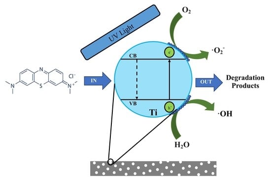
Photocatalysts are materials capable of producing photoexcited electrons by absorbing light. Photoexcited electrons then elevate from the valence band gap to the conduction band gap and generate electron–hole pairs (e-/h+) that produce transformation of reaction participants. The resulting pair (e-/h+) acts to reduce and/or oxidize compounds adjacent to the reactant surfaces, making this method of contaminant treatment particularly effective for organic contaminants [24]. TiO2, ZnO, SnO2, and CeO2 are heterogeneous photocatalysts that are abundant in nature and utilized in semi-conductor applications [25]. Heterogenous metal oxides such as titanium are widely used in photocatalytic applications because of the ability to produce positive electron holes that act to oxidize organic solutions and decompose water in the presence of UV light under ambient conditions [26,27]. TiO2 is considered a superior photocatalyst for organic pollutants in comparison to other metal oxides because it possesses photostability and low toxicity [28,29,30]. The band gap is a measure of energy needed to promote an electron from the valence band to the conduction band and is generally considered a measure of reactivity of the photocatalyst, e.g., the higher the band gap, the more energy garnered during photoexcitation. Anatase has a larger band gap (3.2 eV) than rutile (3.0 eV), which has been shown to reduce the light absorbed, but it increased the oxidation ability of electrons [31]. One means of increasing the band gap, reactivity, and absorbance is to functionalize the catalyst with MAH. The addition of MAH to the TiO2 surface has been shown to increase the band gap, thus making the photocatalyst more reactive [32].
1.4. Photocatalytic Treatment of Organic Contaminants
Photocatalytic decomposition of organic pollutants is a promising technology in which a catalyst generates an ·OH radical by oxidation of OH− anions or generation of O2− radicals by reduction of O2 [33]. Organic contaminants derived from non-point sources resist treatment within traditional best management practice. In order to reduce organic contaminants from non-point sources, water is collected and treated at wastewater facilities using photocatalysis [4]. Current treatment techniques for organic contaminants in wastewater involve slurrying TiO2 in order to optimize the surface area of reactive sites available during treatment [34]. While effective, TiO2 slurries require secondary or membrane filtration to ensure nanoparticulates are not introduced to the environment as new contaminants and to quench free radical presence [35]. As our understanding of nanoparticles in the environment grows, immobilization of TiO2 on substrates for treatment of contaminants has become more prevalent. Different methods of immobilizing TiO2 nanoparticles have been utilized such as bonding to activated carbon [36], plastics [37], and clays [38]. More recently, photocatalytic decomposition methods have been studied for stormwater and groundwater treatment [39,40]. In addition to TiO2, other catalysts can also be utilized as an effective treatment technology [41,42,43,44,45]. The development of innovative technologies which utilize immobilized photocatalysts can be used to mitigate the volume of organic contaminants treated at wastewater facilities.
1.5. Photocatalytic Concrete
The capabilities of photocatalytic concrete to reduce air and organic pollutants have been extensively studied with commercially available cements. TX Active® is a commercially available cement containing TiO2 and has been industrialized in Italy, France, and Belgium [46], along with the United States [47]. The inclusion of TiO2 in pervious concrete has been shown to degrade air pollutants as well [8]. However, the efficiency of a photocatalyst mixed within the concrete structure has been questioned due to the limited amount of photocatalyst exposed to the surface [48]. Therefore, various forms of photocatalytic coatings have been produced to optimize the surface area of the photocatalyst exposed to UV light. The application of a photocatalytic coating has been seen in site demonstrations in Belgium [49] and the United States [50,51], along with many others. Abrasion has been known to dislodge TiO2 from the surface, leaving unreactive pieces of pavement [50]. Further studies elucidated that the photocatalytic capabilities of the coatings significantly decreased after one month [22].
2. Results and Discussion
2.1. Validation of the Functionalization of Ti-MAH
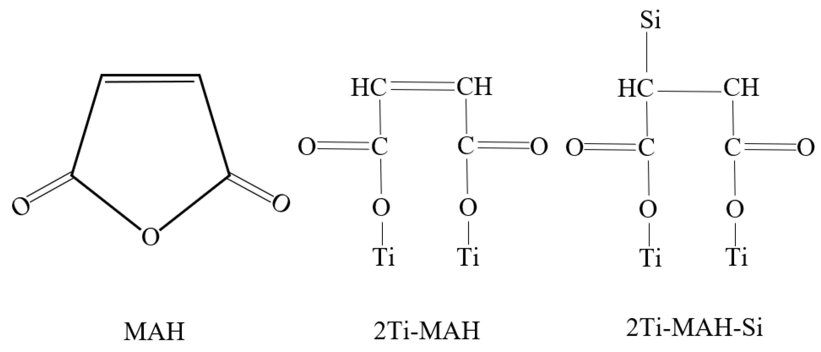
Functionalization of TiO2 to MAH was validated using FTIR and XRD. Ti-MAH composites were prepared at a 1:1 ratio for all analyses. FT-IR measurements show a shift in and broadening of the carboxylate peaks in MAH, verifying functionalization (Figure 1). The annotation of each spectrum is shown in the supplementary information. The major structure arrangement from analysis is two C-O-Ti arranged in an open monodentate configuration (Figure 2) [32].
FTIR analysis verified that 3Ti-MAH was not optimal (Figure 1). Therefore, additional photocatalytic testing was performed using 2Ti-MAH. The photocatalytic testing discussed later corroborates the enhanced reactivity in cement when a 2:1 ratio of the material is compared to a 3:1 ratio, while both are more reactive than TiO2.
XRD denoted both anatase and rutile peaks, with the anatase peak intensity being more abundant (Figure 3a). After TiO2 was functionalized to MAH, an amorphous structure was detected during XRD analysis, starting at about 38° and ending at a 58° 2θ angle (Figure 3b). Therefore, indirect evidence of functionalization is present. The crystallinity index of Ti-MAH was calculated to be 66.75%.
2.2. Validation of Ti-MAH Bonding to Silica within OPC
Immobilizing the photocatalysis (TiO2) within the cement is important to the sustainability and reactivity for continuous treatment. The bonding is theorized to occur in various phases of silicates during cement hydration; specifically, calcium-silica-hydrate (C-S-H) gel remains amorphous in structure during cement hydration. During the process of functionalization, the double bond of the maleic anhydride opens up and is fixed onto amorphous silica, similar to the manner of grafting MAH to a polyolefin [52]. In order to verify that functionalized Ti-MAH bonded to the C-S-H paste during curing, various different forms of amorphous surrogate silicas were used to simulate the bonding of the various silica phases of the cement paste, as well as the point of bonding. This was conducted in a similar process to the functionalization of TiO2 to MAH. Silica was added to methanol at a 1:1 ratio of silica to Ti-MAH. Solutions were continuously stirred for 4 h after equilibration to promote bonding, to be referred to in this paper as Ti-MAH-Si. The resultant solution was heated at 65 °C and continuously stirred for 12 h. Ti-MAH-Si was dried at 35 °C for 24 h, and the dried residuals were ground to an equivalent gradation using a mortar and pestle. FT-IR, XRD, and SEM/EDS analyses were performed on powder from the same batch.
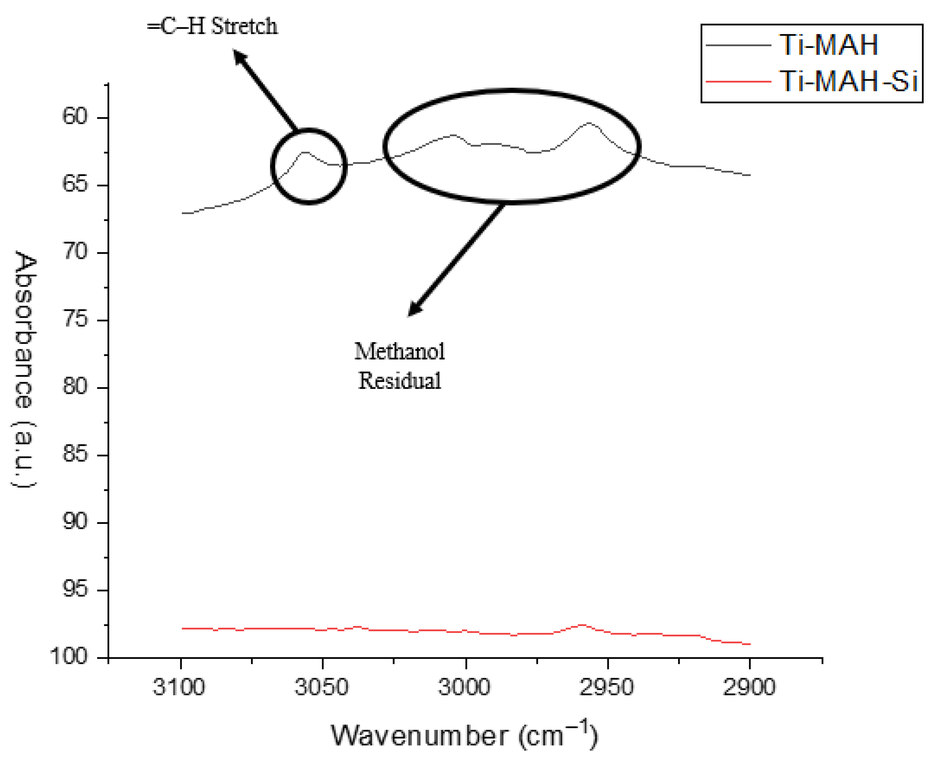
FTIR was performed on Ti-MAH and Ti-MAH-Si to determine bonding points to MAH (Figure 4). The two spectra demonstrate the vibration changes with the silica addition. The shift in and broadening of the MAH carboxylate peaks are still present, while some additional peaks are shown below 1500 cm−1. These vibration changes correlate with the silica spectra and are justified considering the silica addition. The primary peak of interest, which validates the MAH-Si bond, is the C-H stretch peak. The C-H stretch indicates whether a single bond, double bond, or triple bond is present in the structure. Vibrational peaks of the =C-H stretch in MAH are 3124 cm−1 [53].
Figure 5 shows that the =C-H stretch in Ti-MAH is present. This peak is no longer present in the Ti-MAH-Si spectra seen in Figure 5, which verifies that the double bond breaks to bond silicon to Ti-MAH. The theorized structures of MAH, 2Ti-MAH, and 2Ti-MAH-Si are presented in Figure 6. (See the Supplementary Materials).
Powders prepared for FTIR were also used for scanning electron microscopy (SEM) analysis. Figure 7 shows an SEM image in backscatter electron mode with energy-dispersive X-ray (EDS) used for elemental mapping of ground silica powder that had undergone functionalization. The Ti-MAH particle within the beam focus exhibits extensive coating of the silica particles, showing evidence of the bond to silica. Some of the rougher surfaces which lack complete coverage are either outside the beam focus or appear to exhibit less TiO2 bonds. Therefore, the same process was conducted on a fumed silica (Figure 8), a common supplementary cementitious material.
Fumed silica is a nanoparticle synthesized by pyrolysis processes; therefore, it lacks the rough edges present in the ground silica in Figure 7. In comparison, Figure 9 shows the elemental mapping of titanium and silicon functionalized on fumed silica particles. The elemental mapping imagery very clearly indicates that titanium is always present where silicon is present. From this imagery, it can be determined that the titanium evenly coats the silica particles. While both images validate TiO2 coating the silica, the fumed silica has a more homogenous coating which is more correlative to the C-S-H gel in the cement.
The C-S-H phase is the most abundant hydration product of Portland cement [54]. C-S-H grows in nanocrystalline structures surrounded by amorphous regions called the interfacial transition zone or ITZ [55]. Theoretical bonding of Ti-MAH is proposed in the amorphous regions of C-S-H. In order to support this hypothesis, Ti-MAH was analyzed within the cement paste by SEM after cyclic testing of reactivity was completed (Figure 10a,b). The imagery shows Ti-MAH clumped within certain regions of the cement pastes, with the largest clumps averaging 250 microns in width. These clumps act as micro-aggregated TiO2 within the cement paste.
The heterogenous consistency is theorized to be from Ti-MAH bonding to C-S-H. Further analysis along the boundary of the aggregated TiO2 and the main cement paste composite verified the immobilization of the particles due to bonding within C-S-H (Figure 10b). Herein, amorphous C-S-H is interlocked with the aggregated TiO2 with crystal phases growing into C-S-H, substantiating complete immobilization. An interfacial transition zone (ITZ) is found surrounding the boundary of the aggregate TiO2 clumps, verifying that it acts as an aggregated particle [56].
A cross-section was taken from a randomized section of the sample in order to calculate the average surface area of the TiO2 remaining after continuous cyclic reactivity testing (Figure 11). The SEM cross-section image was converted to a binary threshold in Image J. The surface area of TiO2 relative to the entire sample cross-section was calculated at 6.83% including the aggregated TiO2, as seen in Figure 10a.
Titanium nanoparticles are known to act as nucleation sites for cement hydration products that form around the particle. Aggregated TiO2 is hypothesized to occur as the C-S-H gel crystalizes within the pore space, and nucleation occurs. Additionally, maleic acid is a superplasticizer and dispersant which retards the rate of hydration. Retardation of the hydration and crystallization of cement paste occurs at a slower pace than nucleation, forming ion gradients. Mobile phases such as calcium and aluminum diffuse away from the TiO2 across the ITZ and form crystalline calcium hydrate structures, as seen in Figure 10b. Less mobile phases including the anhydrates and silicates form hydration products near the interfacial zone of aggregated TiO2 and the rest of the cement paste where amorphous C-S-H forms, containing residual water from hydration and ion separation. The formation of this ITZ along the anhydrate boundary clearly immobilizes the titanium within the paste while maintaining the theoretical reduced composite band gap of the Ti-MAH structure. Physical immobilization of the Ti-MAH compound within the paste at preferential orientations is only a portion of the analysis as it does not verify improved photocatalytic reactivity relative to TiO2 inter-ground with cement pastes during mixing.
2.3. Cyclic Photocatalytic Reactivity Testing of TiO2 Versus Ti-MAH in Cement
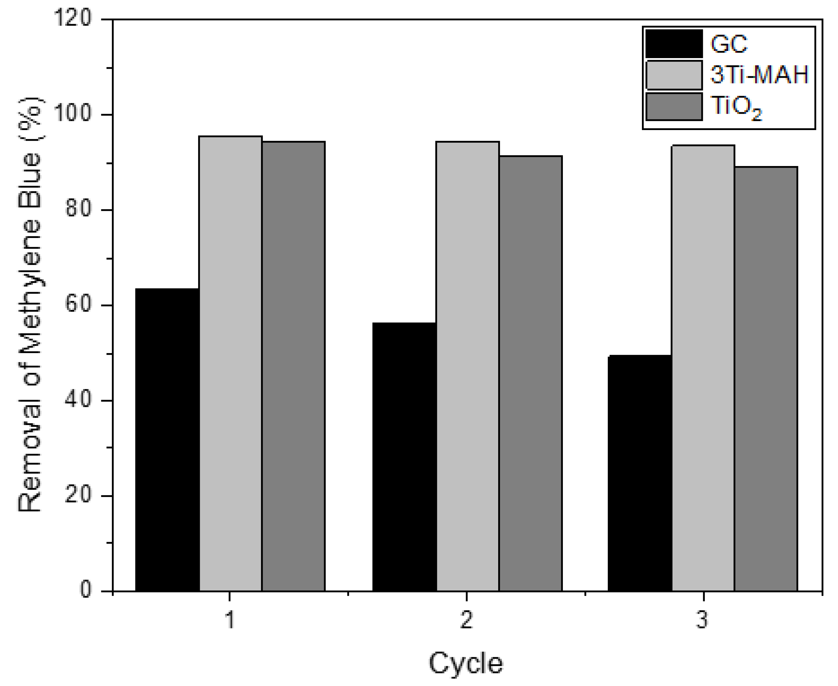
Photocatalytic reactivity testing was first performed on the mixes from Table 1 utilizing 3Ti-MAH and the ISO standard concentration of 10 mg/L methylene blue. Three repeated cycles of reactivity testing were performed on each batch, in order to compare the photocatalytic reactivity of the cement over time and across photocatalysts. Considering the kinetics of dye degradation, specifically methylene blue, have been previously studied [57,58], only cyclic testing was performed for this study. Figure 12 presents the results of the photocatalytic capacities over cycles. The OPC utilized was a gray cement and therefore is denoted as the gray control (GC), while the TiO2 and 3Ti-MAH mixtures are denoted as such. Each cycle of testing was performed over 45 min. The 3Ti-MAH mixture consistently tested more reactive than the gray control and TiO2 mixture and maintained that reactivity over time, which verifies that immobilization of the photocatalyst using Ti-MAH improves reactivity.
After FT-IR analysis was performed on Ti-MAH, it was determined that a 2:1 ratio of TiO2 to MAH could be more reactive. Therefore, additional reactivity testing was conducted on a 2:1 ratio; however, titanium amounts were varied to include both 1.5% and 7% TiO2 by weight of cementitious materials (Table 2). Cycle testing was again conducted for three cycles at 30 min instead of 45 min to determine if 2Ti-MAH was more reactive than 3Ti-MAH (Figure 13). The results indicate that 2Ti-MAH cycled over 30 min performed comparably in the decomposition rates and concentration of MB+ to 3Ti-MAH maintained at 45 min. Therefore, the ratio of 2Ti-MAH was determined to be a more optimal ratio for reactivity and improved performance.
2.4. Stability of MB+ in Photocatalytic Testing
The rates of decomposition of MB+ must be evaluated as a function of the MB+ concentration, mass of TiO2, and pH of the solution as MB+ decomposition is highly pH-dependent. High-pH or alkaline solutions react with methylene blue, a cationic thiazine dye, resulting in the decay of MB+ and the formation of methylene violet Brenthsen when the solution pH rises above 9.0 S/U [23]. The rate of MB+ decomposition is dependent upon the concentration of hydroxyls in solution as well as the dye itself. Methylene violet is essentially a hydrolysis decomposition product that may decay further under sustained alkaline conditions. Therefore, it is necessary to validate the use of MB+ as an indicator of the photocatalytic abilities of cement pastes, as solutions directly in contact with the wetted surface of fresh cements may experience sustained, highly alkaline conditions [59]. Excess hydroxyls from the hydration process such as calcium hydroxide are held in the cement pores until flushed [60]. During flushing of the pores, free hydroxyls diffuse out into the free solution, over time raising the pH of aqueous solutions immediately in contact with the wetted cement surface.
The pH of the initial 10 mg/L MB+ solution was approximately 8 to 8.2 S/U. After each cycle, the treated solutions were measured to determine if a correlation of pH with reactivity or MB+ decay was present in the experimental design. During the first cycle, the pH of the control gray cement, GC, was over 11.0 S/U. However, with each iterative cycle, the pH of the solutions decreased until such time as there was no appreciable difference from the initial to the final pH, occurring at the end of cycle 3. This implies a nucleophile attack on MB+ from the excess hydroxyls freed during the flushing of the cement in the form of Ca(OH)2, which could occur in the initial cycles. As the presence of excess hydroxyls in solutions decreases, the nucleophile attack decreases, which functions to increase the initial decomposition rate of the MB+ compound relative to the final measurement. Each sample possessed the same water-to-cement ratio and weight of cementitious material. Therefore, each sample must also possess the same number of excess hydroxyls released into solution, and hence the nucleophile attack must cease by the third cycle for all samples.
If the nucleophile attack has ceased by the third cycle, the difference in performance between each sample mixture must be attributable to photocatalytic degradation of MB+. Indeed, photocatalytic degradation of MB+ should result in the formation of sulfuric acid and carbon dioxide gas. The sulfuric acid may be neutralized by the buffering capacity of the cement itself until the cement lacks mitigating capacity. Carbon dioxide gas reacts with the cement to form calcium carbonate, reducing the overall pH and making the cement more prone to sulfate attack. The point at which excess hydroxyls are no longer freed by the aqueous solution is commonly considered the carbonation point of the cement or concrete material. The SEM (Figure 10a,b) imagery confirms the lack of portlandite in the samples after continuous cycle testing in the GC control and thus validates that the nucleophile attack ceased.
In an effort to further validate that functionalization is the primary reason for the improved reactivity of the Ti-MAH samples, Hydrion One Drop 1.0–11.0 indicator solution was applied to the top face, bottom face, and a broken cross-section of a 2Ti-MAH sample (Figure 14). Surface dying with phenolphthalein is commonly performed to assess the rate and/or point at which carbonation of the cement occurs [61]. However, phenolphthalein would not show the range of the pH of a cement sample with the distance from an exposed surface and requires an uncarbonated control sample. The indicator dye verified that the pH within the cement sample increased with the distance from the surface exposed to MB+ solutions during treatment. Surfaces directly exposed to the MB+ solution during cycles are dyed yellowish orange, indicating a pH of approximately 6 S/U. As the distances increase from the treatment surface, the dye coloration exhibits a color ramp or gradient from light grayish blue to intense purple, representing a rise in pH above 11 S/U. The cross-section further validates that the pH was reduced to below 8.0 pH in Ti-MAH and that the difference in performance is from the enhanced reactivity due to functionalization.
2.5. Photocatalytic Capabilities of 2Ti-MAH in White Cement Versus Commercially Available Cement
While the increased reactivity of 2Ti-MAH compared to TiO2 was demonstrated in trials utilizing gray cement, additional testing was performed using white cement to compare against a commercially available photocatalytic cement. The exact percent of TiO2 in the commercially available cement is unknown; however, it is estimated to be approximately 5–8%. Therefore, 2Ti-MAH was inter-ground with a white cement base from the same source as the commercially photocatalytic available cement. Four 30 min cycles were performed, as shown in Figure 15. Similar removal rates are seen in cycles 1–3, with 2Ti-MAH being more reactive and retaining a greater degradation percent. Between cycles 3 and 4, the commercially available photocatalytic cement decreases in efficiency by more than two times that of 2Ti-MAH. 2Ti-MAH remains equally as reactive as the cycle before. The rapid decrease in the removal capacity of the commercially available cement signifies fouling on the surface; therefore, further cycles were not tested. Additional experimentation and cycling of 2Ti-MAH against other organic contaminants are needed to understand how it will compare fully to current photocatalytic cements. However, the results validate that using 2Ti-MAH is a superior process for the development of photocatalytic cement.
3. Experimental Methods
Experimental methods are presented in sequence from preparation of the composite materials, functionalization of the catalyst, cement mixtures and curing, and then assessment of reactivity and longevity. Each step of the procedural methods documented below draws upon the background presented above.
3.1. Functionalization of Ti-MAH
Titanium dioxide was originally functionalized to maleic anhydride at ratios of three to one (3Ti-MAH) and two to one (2Ti-MAH), respectively. Ratios listed above were based upon theoretical reactive bonding sites available in the Ti-MAH group, reactive sites of the functionalized material available in order for the group to bind to cementitious media, and, finally, the minimal amount of titanium required. TiO2 and MAH were dissolved in methanol in these three ratios and heated until the solution temperature equilibrated to 65 °C. Solution maintained a constant temperature for 4 h and was continuously stirred in order to allow for complete functionalization to occur [32]. Solution was then placed in an oven at 35 °C or dried in ambient conditions until only powder remained. The resultant powder was ground by a mortar and pestle to an equivalent particle gradation. Analysis of the functionalized material was performed using Fourier-transform infrared spectroscopy (FTIR) and X-ray diffraction (XRD) to verify permanent structural bonding.
3.2. Materials and Mixture Proportions
In order to test the permanence of bonding within the cementitious paste, mixtures were prepared in small batches and placed in containers compliant with ISO testing procedures. Cement paste was mixed using OPC and ASTM-grade de-ionized water (DI water) at a water-to-cement w/c ratio of 0.485. Mixtures included the incorporation of TiO2 or functionalized TiO2 by an equivalent weight of cementitious material. Type I/II OPC conforming to ASTM C150/C150M was used with a Blaine fineness of 373 m2 = kg (1; 821 ft2 = lb) and a Bogue composition of 55% C3S, 17% C2S, 8% C3A, and 10% C4AF [62,63]. Titanium (IV) oxide, Aeroxide® P25, ACROS Organics was purchased from Thermo Fisher Scientific (Waltman, MA, USA).
XRD analysis of P25 indicated TiO2 was composed of primarily anatase and some rutile, with anatase presenting more intense peaks. Maleic anhydride (99% purity, Lot#MKCJ0038) was purchased from Sigma Aldrich Company (St. Louis, MO, USA), and ACS reagent-grade methanol (99.8% purity) was purchased from Thermo Fisher Scientific. MAH and Ti-MAH powders were individually sealed in containers which were stored in a desiccator to prevent hydration. TiO2 and Ti-MAH were inter-ground by a mortar and pestle with the proportioned amounts of cement for their respective mixes (Table 1 and Table 2). The ground powders were all treated as cementitious material with photocatalytic material addition acting as a supplementary cementitious material (SCM). Original testing was performed on 3Ti-MAH with the weight of TiO2 introduced into the cement at seven percent. However, additional testing was performed on 2Ti-MAH with a varying weight of photocatalytic material after FTIR analysis indicated optimization of the composite could improve reactivity. The water-to-cement ratio was kept constant for all mixes at 0.485 throughout the original and revised mixing. Mixture proportions for the batches are shown in Table 1 and Table 2 with each batch being mixed and tested in triplicate.
3.3. Mixing and Curing Procedure
Samples were mixed in transparent borosilicate containers with a diameter of 2-1/8” and height of 2-9/16” for translation to photocatalytic testing described below. (Figure 16). Mixing was performed using hand incorporation of all materials. Each container was vibrated using a vortex mixer set to touch mode for approximately 15 s to remove air and to ensure complete mixing. Samples were then placed in a standard environmental chamber set to 100% humidity, 23 °C, and allowed to cure for 21 days to ensure complete cement hydration. After initial curing was completed, the samples were placed in an environmental chamber maintained at 50% humidity and 23 °C for 7 days to thoroughly dry out prior to testing.
3.4. Photocatalytic Testing
The catalyst reactivity testing procedure was adapted from the International Organization for Standardization standard ISO 10,678 (Fine ceramics (advanced ceramics, advanced technical ceramics)–Determination of photocatalytic activity of surfaces in an aqueous medium by degradation of methylene blue) [64]. Methylene blue (MB+) is an organic chloride salt commonly used to test pollutant reduction capacity in semiconductor photocatalysis because it highlights the efficacy of the photocatalytic process for removal in water pollutants [23]. MB+ has a high absorptivity and a maximum absorption at a wavelength between 660 and 665 nm [11,65,66]. The features of MB+ absorption allow for a drastic color change as the compound breaks down into CO2 and H2O byproducts [67,68,69].
An amount of 35 mL of 10 mg/L methylene blue was pipetted onto the cement and conditioned in a dark room for 12 h prior to reactivity testing to minimize the adsorption properties of the cement. UVA/B/C lights operating at a range of wavelengths from 550 to 250 nm were precisely placed above the target at a height of 4”. Prior to testing, each sample was rinsed in MeOH, followed by DI water to remove lose material and residual dye. An amount of 35 mL of 10 mg/L methylene blue was again pipetted onto each cement sample which was then immediately placed under the lamp upon the target. Each sample was irradiated initially for 45 min when it was removed from the target. Solutions were extracted from the container and cooled in a darkened container prior to analysis.
Methylene blue analysis was conducted using a DR3900 Hach UV–Vis spectrometer and matching quartz cuvettes. Prior to testing, calibration of the methylene blue concentrations was performed with a linear relationship achieved between absorption and concentration. Peak wavelength for methylene blue was measured at 665 nm wavelength, with full spectrum analysis performed every three samples. Each absorbance measurement was performed, at minimum, in triplicate or until variations in values were statistically invariable.
4. Conclusions
Silica was bonded to photocatalytic titanium using the simple and efficient procedure of bridging the two with maleic anhydride (MAH). Bonding the Ti-MAH-Si together allowed for the optimal orientation of the titanium particles within the silicon. Multiple robust lines of evidence were used to verify the bond formation between Ti-MAH and silica. For each iteration, ratio adjustments of Ti to MAH or the mass of titanium within the cement samples were tested to determine the bond strength, reactivity, and longevity of reactivity. The optimal ratio for enhanced reactivity performance was found to be a 2:1 ratio of TiO2/MAH. Additionally, when Ti-MAH bonded within the cement pastes was cycled, the results clearly delineate an increased reduction in the methylene blue (MB+) concentration over time and an improved longevity of the cement pastes. Using effectively orientated and functionalized titanium within cement has great potential to enhance the photocatalytic capacities of concrete and therefore improve the treatment of non-point and point sources of organic contaminants. If the photocatalytic cement were used as a granular filter of media, an enhanced organic removal capacity would occur considering that free radicals would be generated over a greater surface area with a longer contact time. Furthermore, cement represents only one use for bonding Ti-MAH to silicon; there are many applications of use which could include paints, coatings and adhesives, construction building materials, and plastic modifiers. Given the potential uses, ease of preparation and application, and enhancement in performance over time, this technique is a promising means for reducing organic contaminants in air or water.
Supplementary Materials
The following are available online at https://0-www-mdpi-com.brum.beds.ac.uk/article/10.3390/catal11080938/s1, Figure S1: Crystalline Area of TiO2, Figure S2: Crystalline Area of Ti-MAH, Table S1: Rutile Miller Index; Table S2: Anatase Miller Index, Figure S3: FT-IR Spectrum of TiO2, Figure S4: FT-IR Spectrum of Maleic Anhydride, Figure S5: FT-IR Spectrum of Ti-MAH, Figure S6: FT-IR Spectrum of Ti-MAH-Si.
Author Contributions
Funding acquisition, M.L.H.; investigation, H.M.M.; methodology, H.M.M.; supervision, M.L.H.; writing—original draft, H.M.M.; writing—review and editing, M.L.H. All authors have read and agreed to the published version of the manuscript.
Funding
This research was funded in whole or in part by NSF Grant #EEC—1840654.
Institutional Review Board Statement
No living subjects were utilized during this research.
Informed Consent Statement
No informed consent was needed.
Data Availability Statement
All data is available whole or in part within this manuscript and Supplement Information.
Acknowledgments
This technology is protected by a provisional patent.
Conflicts of Interest
The authors declare no conflict of interest.
References
- Brown, J.N. Partitioning of Chemical Contaminants in Urban Stormwater. Ph.D. Thesis, University of Otago, Dunedin, New Zealand, 2002. [Google Scholar]
- Foster, G.D.; Roberts, E.C.; Gruessner, B.; Velinsky, D.J. Hydrogeochemistry and transport of organic contaminants in an urban watershed of Chesapeake Bay (USA). Appl. Geochem. 2000, 15, 901–915. [Google Scholar] [CrossRef]
- ITRC (Interstate Technology & Regulatory Council). PFAS Technical and Regulatory Guidance Document and Fact Sheets PFAS-1; Interstate Technology & Regulatory Council, PFAS Team: Washington, DC, USA, 2020; Available online: https://pfas-1.itrcweb.org/ (accessed on 1 July 2021).
- Mahlambi, M.M.; Ngila, C.J.; Mamba, B. Recent Developments in Environmental Photocatalytic Degradation of Organic Pollutants: The Case of Titanium Dioxide Nanoparticles—A Review. J. Nanomater. 2015, 2015, 1–29. [Google Scholar] [CrossRef] [Green Version]
- Spatari, S.; Yu, Z.; Montalto, F.A. Life cycle implications of urban green infrastructure. Environ. Pollut. 2011, 159, 2174–2179. [Google Scholar] [CrossRef]
- Brown, R.A.; Borst, M. Evaluation of Surface Infiltration Testing Procedures in Permeable Pavement Systems. J. Environ. Eng. 2014, 140, 04014001. [Google Scholar] [CrossRef]
- Welker, A.L.; Barbis, J.D.; Jeffers, P.A. A Side-by-Side Comparison of Pervious Concrete and Porous Asphalt. J. Am. Water Resour. Assoc. (JAWRA) 2012, 48, 809–819. [Google Scholar] [CrossRef]
- Asadi, S.; Hassan, M.; Kevern, J.; Rupnow, T.D. Development of Photocatalytic Pervious Concrete Pavement for Air and Storm Water Improvements. Transp. Res. Rec. J. Transp. Res. Board 2012, 2290, 161–167. [Google Scholar] [CrossRef]
- Kayhanian, M.; Li, H.; Harvey, J.T.; Liang, X. Application of permeable pavements in highways for stormwater runoff management and pollution prevention: California research experiences. Int. J. Transp. Sci. Technol. 2019, 8, 358–372. [Google Scholar] [CrossRef]
- Monrose, J.; Tota-Maharaj, K. Permeable Pavements as Low Impact Development Practices for Urban Runoff Mitigation and Sustainable Stormwater Management within the Built Environment for the Caribbean; Conference: 25th Silver Anniversary Annual Caribbean Water and Wastewater Association (CWWA) Conference & Exhibition at: Port of Spain, Trinidad and Tobago, West Indies 2016; pp. 24–28. Available online: https://cwwa.net/publication/permeable-pavements-as-low-impact-development-practices-for-urban-runoff-mitigation-and-sustainable-stormwater-management-within-the-built-environment-for-the-caribbean-presentation/ (accessed on 31 July 2021).
- Spahr, S.; Teixidó, M.; Sedlak, D.L.; Luthy, R.G. Hydrophilic trace organic contaminants in urban stormwater: Occurrence, toxicological relevance, and the need to enhance green stormwater infrastructure. Environ. Sci. Water Res. Technol. 2020, 6, 15–44. [Google Scholar] [CrossRef] [Green Version]
- Environmental Protection Agency (EPA), Office of Water. Preliminary Data Summary of Urban Storm Water Best Management Practices; EPA-821-R-99-012; Environmental Protection Agency: Washington, DC, USA, 1999.
- Todd, G.; Chessin, R.; Colman, J. Toxicological Profile for Total Petroleum Hydrocarbons (TPH); Agency for Toxic Substances and Disease Registry: Atlanta, Georgia, 1999. [Google Scholar]
- Björklund, K. Sources and Fluxes of Organic Contaminants in Urban Runoff. Ph.D. Thesis, Chalmers University of Technology, Göteborg, Sweden, 2011. [Google Scholar]
- Mangiafico, S.S.; Newman, J.; Merhaut, D.J.; Gan, J.; Faber, B.; Wu, L. Nutrients and Pesticides in Stormwater Runoff and Soil Water in Production Nurseries and Citrus and Avocado Groves in California. HortTechnology 2009, 19, 360–367. [Google Scholar] [CrossRef] [Green Version]
- Ellis, J. Pharmaceutical and personal care products (PPCPs) in urban receiving waters. Environ. Pollut. 2006, 144, 184–189. [Google Scholar] [CrossRef]
- Xiao, F.; Simcik, M.F.; Gulliver, J. Perfluoroalkyl acids in urban stormwater runoff: Influence of land use. Water Res. 2012, 46, 6601–6608. [Google Scholar] [CrossRef] [PubMed]
- Codling, G.; Yuan, H.; Jones, P.D.; Giesy, J.P.; Hecker, M. Metals and PFAS in stormwater and surface runoff in a semi-arid Canadian city subject to large variations in temperature among seasons. Environ. Sci. Pollut. Res. 2020, 27, 18232–18241. [Google Scholar] [CrossRef]
- Hassaan, M.A.; Nemr, A.E. Health and Environmental Impacts of Dyes: Mini Review. Am. J. Environ. Sci. Eng. 2017, 1, 64–67. [Google Scholar] [CrossRef]
- Raval, N.P.; Shah, P.U.; Shah, N.K. Malachite green “a cationic dye” and its removal from aqueous solution by adsorption. Appl. Water Sci. 2016, 7, 3407–3445. [Google Scholar] [CrossRef] [Green Version]
- Delnavaz, M.; Ayati, B.; Ganjidoust, H.; Sanjabi, S. Kinetics study of photocatalytic process for treatment of phenolic wastewater by TiO 2 nano powder immobilized on concrete surfaces. Toxicol. Environ. Chem. 2012, 94, 1086–1098. [Google Scholar] [CrossRef]
- Osborn, D.; Hassan, M.; Asadi, S.; White, J. Durability Quantification of TiO2 Surface Coating on Concrete and Asphalt Pavements. J. Mater. Civ. Eng. 2014, 26, 331–337. [Google Scholar] [CrossRef]
- Mills, A.; Hazafy, D.; Parkinson, J.; Tuttle, T.; Hutchings, M.G. Effect of alkali on methylene blue (C.I. Basic Blue 9) and other thiazine dyes. Dye. Pigment. 2011, 88, 149–155. [Google Scholar] [CrossRef]
- Fujishima, A.; Rao, T.N.; Tryk, D.A. Titanium Dioxide Photocatalysis. J. Photochem. Rev. 2000, 1, 1–21. [Google Scholar] [CrossRef]
- Khan, M.M.; Adil, S.; Al-Mayouf, A. Metal oxides as photocatalysts. J. Saudi Chem. Soc. 2015, 19, 462–464. [Google Scholar] [CrossRef] [Green Version]
- Martha, S.; Sahoo, P.C.; Parida, K.M. An overview on visible light responsive metal oxide based photocatalysts for hydrogen energy production. RSC Adv. 2015, 5, 61535–61553. [Google Scholar] [CrossRef]
- Fujishima, A.; Honda, K. Electrochemical Photolysis of Water at a Semiconductor Electrode. Nature 1972, 238, 37–38. [Google Scholar] [CrossRef] [PubMed]
- Grande, F.; Tucci, P. Titanium Dioxide Nanoparticles: A Risk for Human Health? Mini-Rev. Med. Chem. 2016, 16, 762–769. [Google Scholar] [CrossRef]
- Poulopoulos, S.G.; Yerkinova, A.; Ulykbanova, G.; Inglezakis, V.J. Photocatalytic treatment of organic pollutants in a synthetic wastewater using UV light and combinations of TiO2, H2O2 and Fe(III). PLoS ONE 2019, 14, e0216745. [Google Scholar] [CrossRef] [PubMed]
- Khdary, N.H.; Alkhuraiji, W.S.; Sakthivel, T.S.; Khdary, D.N.; Salam, M.A.; Alshihri, S.; Al-Mayman, S.I.; Seal, S. Synthesis of Superior Visible-Light-Driven Nanophotocatalyst Using High Surface Area TiO2 Nanoparticles Decorated with CuxO Particles. Catalysts 2020, 10, 872. [Google Scholar] [CrossRef]
- Luttrell, T.; Halpegamage, S.; Tao, J.; Kramer, A.; Sutter, E.A.; Batzill, M. Why is anatase a better photocatalyst than rutile?—Model studies on epitaxial TiO2 films. Sci. Rep. 2014, 4, 4043. [Google Scholar] [CrossRef] [Green Version]
- Del Castillo, P.C.H.; Manuel, S.R.; Ruiz, F. An Easy and Efficient Method to Functionalize Titanium Dioxide Nanoparticles with Maleic Anhydride. Soft Nanosci. Lett. 2014, 04, 53–62. [Google Scholar] [CrossRef] [Green Version]
- Umar, M.; Abdul, H. Photocatalytic Degradation of Organic Pollutants in Water; Rashed, M.N., Ed.; IntechOpen: London, UK, 2013; Available online: https://www.intechopen.com/chapters/42060 (accessed on 31 July 2021). [CrossRef] [Green Version]
- Chong, M.N.; Jin, B.; Chow, C.; Saint, C. Recent developments in photocatalytic water treatment technology: A review. Water Res. 2010, 44, 2997–3027. [Google Scholar] [CrossRef]
- Yang, G.; Li, C. Electrofiltration of silica nanoparticle-containing wastewater using tubular ceramic membranes. Sep. Purif. Technol. 2007, 58, 159–165. [Google Scholar] [CrossRef]
- Alalm, M.G.; Tawfik, A.; Ookawara, S. Enhancement of photocatalytic activity of TiO2 by immobilization on activated carbon for degradation of pharmaceuticals. J. Environ. Chem. Eng. 2016, 4, 1929–1937. [Google Scholar] [CrossRef]
- Laurance, J. Photocatalytic Treatment of Stormwater Runoff Using Puralytics LilyPad. Honors Baccalaureate of Science in Environmental. Engineering Thesis, Oregon State University, Corvallis, OR, USA, 2016. [Google Scholar]
- Mustapha, S.; Ndamitso, M.M.; Abdulkareem, A.S.; Tijani, J.O.; Shuaib, D.T.; Ajala, A.O.; Mohammed, A.K. Application of TiO2 and ZnO nanoparticles immobilized on clay in wastewater treatment: A review. Appl. Water Sci. 2020, 10, 49. [Google Scholar] [CrossRef] [Green Version]
- Doudrick, K.; Monzón, O.; Mangonon, A.; Hristovski, K.; Westerhoff, P. Nitrate Reduction in Water Using Commercial Titanium Dioxide Photocatalysts (P25, P90, and Hombikat UV100). J. Environ. Eng. 2012, 138, 852–861. [Google Scholar] [CrossRef]
- Zhao, C.; Wang, Z.; Wang, C.; Li, X.; Wang, C.-C. Photocatalytic degradation of DOM in urban stormwater runoff with TiO2 nanoparticles under UV light irradiation: EEM-PARAFAC analysis and influence of co-existing inorganic ions. Environ. Pollut. 2018, 243, 177–188. [Google Scholar] [CrossRef]
- Chen, C.-Y.; Hsiao, P.-H.; Wei, T.-C.; Chen, T.-C.; Tang, C.-H. Well incorporation of carbon nanodots with silicon nanowire arrays featuring excellent photocatalytic performances. Phys. Chem. Chem. Phys. 2017, 19, 11786–11792. [Google Scholar] [CrossRef] [PubMed]
- Tang, C.-H.; Chen, K.-Y.; Chen, C.-Y. Solution-processed ZnO/Si based heterostructures with enhanced photocatalytic performance. New J. Chem. 2018, 42, 13797–13802. [Google Scholar] [CrossRef]
- Yang, T.; Yu, D.; Wang, D.; Yang, T.; Li, Z.; Wu, M.; Petru, M.; Crittenden, J. Accelerating Fe(Ⅲ)/Fe(Ⅱ) cycle via Fe(Ⅱ) substitution for enhancing Fenton-like performance of Fe-MOFs. Appl. Catal. B Environ. 2021, 286, 119859. [Google Scholar] [CrossRef]
- Yu, D.; Wang, L.; Yang, T.; Yang, G.; Wang, D.; Ni, H.; Wu, M. Tuning Lewis acidity of iron-based metal-organic frameworks for enhanced catalytic ozonation. Chem. Eng. J. 2021, 404, 127075. [Google Scholar] [CrossRef]
- Yu, D.; Li, L.; Wu, M.; Crittenden, J.C. Enhanced photocatalytic ozonation of organic pollutants using an iron-based metal-organic framework. Appl. Catal. B Environ. 2019, 251, 66–75. [Google Scholar] [CrossRef]
- Cassar, L.; Beeldens, A.; Pimpinelli, N.; Guerrini, G.L. Photocatalysis of cementitious materials. Int. RILEM Symp. Photocatal. Environ. Constr. Mater. 2007, 131–145. [Google Scholar]
- Cackler, T.; Alleman, J.; Kevern, J.; Sikkema, J. Environmental Impact Benefits with “TX Active” Concrete Pavement in Missouri DOT Two-Lift Highway Construction Demonstration; Iowa State University: Ames, IA, USA, 2012. [Google Scholar]
- Yang, L.; Hakki, A.; Wang, F.; Macphee, D.E.; Yang, L.; Hakki, A.; Wang, F.; Macphee, D.E. Photocatalyst efficiencies in concrete technology: The effect of photocatalyst placement. Appl. Catal. B Environ. 2018, 222, 200–208. [Google Scholar] [CrossRef] [Green Version]
- Boonen, E.; Beeldens, A. Recent Photocatalytic Applications for Air Purification in Belgium. Coatings 2014, 4, 553–573. [Google Scholar] [CrossRef] [Green Version]
- Shen, S.; Burton, M.; Jobson, B.; Haselbach, L. Pervious concrete with titanium dioxide as a photocatalyst compound for a greener urban road environment. Constr. Build. Mater. 2012, 35, 874–883. [Google Scholar] [CrossRef]
- Crain, N.; Mcdonald-Buller, E.; Crain, N.; Juenger, M.; Cros, C.; Terpeluk, A.; Burris, L.; Mcdonald-Buller, E.; Sullivan, D.; Street, G. Laboratory and Field Studies of Photocatalytic NOx and O3 Removal by Coatings on Concrete; The University of Texas at Austin: Austin, TX, USA, 2017. [Google Scholar]
- Samay, G.; Nagy, T.; White, J.L. Grafting maleic anhydride and comonomers onto polyethylene. J. Appl. Polym. Sci. 1995, 56, 1423–1433. [Google Scholar] [CrossRef]
- Layman, A. A Study of the Polarized Infrared Spectrum of Maleic Anhydride. Ph.D. Thesis, Montana State University, Bozeman, MT, USA, 1963. [Google Scholar]
- Beaudoin, J.; Odler, I. (Eds.) Lea’s Chemistry of Cement and Concrete, 5th ed.; Butterworth-Heinemann: Oxford, UK, 2019. [Google Scholar]
- Marchon, D.; Flatt, R.J. (Eds.) Science and Technology of Concrete Admixtures; Elsevier Science Woodhead Publishing: Sawston, UK, 2015. [Google Scholar]
- Nicolas, R.S.; Provis, J.L. The Interfacial Transition Zone in Alkali-Activated Slag Mortars. Front. Mater. 2015, 2, 70. [Google Scholar] [CrossRef] [Green Version]
- McIntyre, H.; Hart, M. Photocatalytic Porous Silica-Based Granular Media for Organic Pollutant Degradation in Industrial Waste-Streams. Catalysts 2021, 11, 258. [Google Scholar] [CrossRef]
- Hsiao, P.-H.; Li, T.-C.; Chen, C.-Y. ZnO/Cu2O/Si Nanowire Arrays as Ternary Heterostructure-Based Photocatalysts with Enhanced Photodegradation Performances. Nanoscale Res. Lett. 2019, 14, 244. [Google Scholar] [CrossRef] [Green Version]
- Grubb, J.; Limaye, H.; Kakade, A. Testing pH of Concrete: Need for a Standard Procedure. Concr. Int. 2007, 29, 78–83. [Google Scholar]
- Hansen, K. Cement Hydration Kinetics; National Precast Concrete Association: Carmel, IN, USA, 2015; Available online: https://precast.org/2016/03/cement-hydration-kinetics/ (accessed on 7 March 2021).
- Lo, Y.; Lee, H. Curing effects on carbonation of concrete using a phenolphthalein indicator and Fourier-transform infrared spectroscopy. Build. Environ. 2002, 37, 507–514. [Google Scholar] [CrossRef]
- ASTM. Standard Specification for Portland Cement; ASTM C150/C150M-16e1; ASTM: West Conshohocken, PA, USA, 2016. [Google Scholar]
- Cao, Q.; Kevern, J.T. Using drinking water treatment waste as a low-cost internal curing agent for concrete. ACI Mater. J. 2015, 112, 69–77. [Google Scholar] [CrossRef]
- International Organization for Standardization. Fine Ceramics (Advanced Ceramics, Advanced Technical Ceramics)—Determination of Photocatalytic Activity of Surfaces in an Aqueous Medium by Degradation of Methylene Blue. 2010. (ISO 10678:2010). Available online: https://www.iso.org/standard/46019.html (accessed on 31 July 2021).
- Milošević, M.; Logar, M.M.; Poharc-Logar, A.V.; Jakšić, N.L. Orientation and Optical Polarized Spectra (380–900 nm) of Methylene Blue Crystals on a Glass Surface. Int. J. Spectrosc. 2013, 2013, 923739. [Google Scholar] [CrossRef] [Green Version]
- Dariani, R.; Esmaeili, A.; Mortezaali, A.; Dehghanpour, S. Photocatalytic reaction and degradation of methylene blue on TiO2 nano-sized particles. Optik 2016, 127, 7143–7154. [Google Scholar] [CrossRef]
- Hou, C.; Hu, B.; Zhu, J. Photocatalytic Degradation of Methylene Blue over TiO2 Pretreated with Varying Concentrations of NaOH. Catalysts 2018, 8, 575. [Google Scholar] [CrossRef] [Green Version]
- Li, R.; Jia, Y.; Bu, N.; Wu, J.; Zhen, Q. Photocatalytic degradation of methyl blue using Fe2O3/TiO2 composite ceramics. J. Alloys Compd. 2015, 643, 88–93. [Google Scholar] [CrossRef]
- Xu, C.; Rangaiah, G.; Zhao, X.S. Photocatalytic Degradation of Methylene Blue by Titanium Dioxide: Experimental and Modeling Study. Ind. Eng. Chem. Res. 2014, 53, 14641–14649. [Google Scholar] [CrossRef]
Figure 1.
FTIR analysis of MAH and Ti-MAH.

Figure 2.
Proposed structure arrangement of 2Ti-MAH.

Figure 3.
(a) XRD diffractogram of P25 titanium dioxide. (b) XRD diffractogram of functionalized Ti-MAH powder.
Figure 3.
(a) XRD diffractogram of P25 titanium dioxide. (b) XRD diffractogram of functionalized Ti-MAH powder.

Figure 4.
FT-IR comparison of Ti-MAH and Ti-MAH-Si.

Figure 5.
FTIR comparison of Ti-MAH and Ti-MAH-Si C-H stretch.

Figure 6.
Proposed structure arrangement of MAH, 2Ti-MAH, and 2Ti-MAH-Si.

Figure 7.
SEM backscatter image with XPS elemental mapping. Silica grains are shown in green hues, while titanium is shown in red. The silica grain shown in the beam focus is thoroughly coated on all faces and edges, indicating homogenous bonding.
Figure 7.
SEM backscatter image with XPS elemental mapping. Silica grains are shown in green hues, while titanium is shown in red. The silica grain shown in the beam focus is thoroughly coated on all faces and edges, indicating homogenous bonding.

Figure 8.
SEM backscatter image with XPS elemental mapping. Silica fume grains are shown in blue hues, while titanium is shown in red.
Figure 8.
SEM backscatter image with XPS elemental mapping. Silica fume grains are shown in blue hues, while titanium is shown in red.

Figure 9.
SEM backscatter image with XPS elemental mapping. Silica fume grains are shown in blue hues, while titanium is shown in red.
Figure 9.
SEM backscatter image with XPS elemental mapping. Silica fume grains are shown in blue hues, while titanium is shown in red.

Figure 10.
(a) SEM secondary electron image of TiO2 immobilized with the cement structure. The blue box marks the location of image 11b. (b) SEM secondary electron image of the interlocking of C-S-H and TiO2 along the boundary of the aggregated TiO2.
Figure 10.
(a) SEM secondary electron image of TiO2 immobilized with the cement structure. The blue box marks the location of image 11b. (b) SEM secondary electron image of the interlocking of C-S-H and TiO2 along the boundary of the aggregated TiO2.


Figure 11.
SEM backscatter image converted to binary to calculate an averaged surface area of TiO2.

Figure 12.
Results of photocatalytic testing of TiO2 and 3Ti-MAH.

Figure 13.
Absorbance over cycles comparison of 2T-iMAH (7%) and 2Ti-MAH (5%).

Figure 14.
pH of 2Ti-MAH sample after cycle testing.

Figure 15.
Absorbance over cycles comparison of 2Ti-MAH versus commercially available photocatalytic cement.
Figure 15.
Absorbance over cycles comparison of 2Ti-MAH versus commercially available photocatalytic cement.

Figure 16.
Photocatalytic testing setup.


Table 1.
Mixture designs’ initial testing.
| Mixture | Portland Cement (g) | TiO2 (g) | 3Ti-MAH (g) | DI Water (g) |
|---|---|---|---|---|
| Control | 14.29 | - | - | 6.93 |
| TiO2 (7%) | 13.29 | 1.00 | - | 6.93 |
| 3Ti-MAH (7%) | 12.96 | - | 1.33 | 6.93 |
Table 2.
Mixture designs’ additional testing.
| Mixture | Portland Cement (g) | TiO2 (g) | 2Ti-MAH (g) | DI Water (g) |
|---|---|---|---|---|
| Control | 14.29 | - | - | 6.93 |
| 2Ti-MAH (1.5%) | 12.96 | - | 1.33 | 6.93 |
| 2Ti-MAH (7%) | 12.79 | - | 1.5 | 6.93 |
Publisher’s Note: MDPI stays neutral with regard to jurisdictional claims in published maps and institutional affiliations. |
© 2021 by the authors. Licensee MDPI, Basel, Switzerland. This article is an open access article distributed under the terms and conditions of the Creative Commons Attribution (CC BY) license (https://creativecommons.org/licenses/by/4.0/).
Share and Cite
MDPI and ACS Style
McIntyre, H.M.; Hart, M.L. Immobilization of TiO2 Nanoparticles in Cement for Improved Photocatalytic Reactivity and Treatment of Organic Pollutants. Catalysts 2021, 11, 938. https://0-doi-org.brum.beds.ac.uk/10.3390/catal11080938
AMA Style
McIntyre HM, Hart ML. Immobilization of TiO2 Nanoparticles in Cement for Improved Photocatalytic Reactivity and Treatment of Organic Pollutants. Catalysts. 2021; 11(8):938. https://0-doi-org.brum.beds.ac.uk/10.3390/catal11080938
Chicago/Turabian StyleMcIntyre, Hannah M., and Megan L. Hart. 2021. "Immobilization of TiO2 Nanoparticles in Cement for Improved Photocatalytic Reactivity and Treatment of Organic Pollutants" Catalysts 11, no. 8: 938. https://0-doi-org.brum.beds.ac.uk/10.3390/catal11080938
Note that from the first issue of 2016, this journal uses article numbers instead of page numbers. See further details here.