
Creating and Preserving Nanoparticles during Co-Sintering of Solid Oxide Electrodes and Its Impact on Electrocatalytic Activity


1
Department of Engineering, Wake Forest University, Winston-Salem, NC 27101, USA
2
Center for Functional Materials, Wake Forest University, Winston-Salem, NC 27101, USA
3
National Energy Technology Laboratory, Morgantown, WV 26507, USA
*
Author to whom correspondence should be addressed.
Catalysts 2021, 11(9), 1073; https://0-doi-org.brum.beds.ac.uk/10.3390/catal11091073
Submission received: 18 August 2021
/
Revised: 1 September 2021
/
Accepted: 3 September 2021
/
Published: 6 September 2021
(This article belongs to the Special Issue Novel Catalyst Materials for Low-Temperature Fuel Cells and Electrolyzers)
Abstract
:A novel processing method that creates and preserves ceramic nanoparticles in solid oxide electrodes during co-sintering at traditional sintering temperatures is introduced. Specifically, carbon templated samarium-doped ceria nanoparticles (nSDC) were successfully integrated with commercial lanthanum strontium cobalt ferrite (LSCF) and commercial SDC powders, producing LSCF-SDC-nSDC cathodes upon processing. The effect of nSDC concentration on cathode electrocatalytic activity was investigated at low operational temperatures, 600 °C–700 °C, with symmetrical cells. Low nSDC loadings, ≤5 wt% nSDC, significantly decreased cell polarization resistance whereas higher loadings increased it. The best electrochemical performance was achieved with 5 wt% nSDC, lowering the polarization resistance by 41% at 600 °C. Fuel cell tests demonstrate that adding 5 wt% nSDC increased the maximum fuel cell power density by 38%. Electrochemical impedance spectra showed substantial improvements in both fuel cell polarization resistance and ohmic resistance, indicating that nSDC increased the electrocatalytically active area of the cathode. This work demonstrates a simple, novel method for effectively increasing electrocatalytic activity of solid oxide electrodes at low operational temperatures.
1. Introduction
The main challenge with operating solid oxide fuel cells (SOFC) at low temperatures (≤700 °C) is the slow kinetics of electrode processes, which hampers power output [1,2,3,4,5,6,7]. Such operation temperatures, however, would enable the use of low-cost SOFC materials and reduce cell degradation rates [8,9,10,11,12]. Thus, there is a need to enhance SOFC electrode catalytic activity to achieve adequate power production at low operational temperatures. Electrocatalytically active sites require a three-phase boundary (TPB), an interface between an oxygen ion conductor, pores through which the gas-phase reactant can be supplied, and a material that serves as both an electronic conductor and a catalyst.
Increasing the TPB concentration would enhance low temperature SOFC performance and one approach to achieve this is the infiltration method, wherein nanoparticles or nanoparticle chemical precursors are introduced into a pre-sintered, porous scaffold of the oxygen ion conducting material [13,14,15,16,17,18]. The porous scaffold is sintered at high temperature, 1300 °C–1550 °C, and the infiltrant is subsequently added at ambient temperature. In the case of infiltrating nanoparticle precursors, a calcination step is required to form the desired phase. That calcination step typically ranges between 400 °C and 850 °C depending on the material. The infiltrated electrode microstructure consists of a three-dimensional percolated network of nanoparticles covering the surface of the coarse, porous scaffold. The infiltrant loading required to form a percolated particle network depends on the porosity, characteristic size, morphology of the scaffold, and particle size of the infiltrated phase [19,20]. However, an infiltrant loading between 30 wt% and 40 wt% of the overall electrode is typically used in practice. To achieve this high loading, numerous successive infiltration and calcination steps are required, adding complexity and cost to SOFC manufacturing. In response to this challenge, we introduce a simple method that creates and preserves nanoparticles within SOFC electrodes during sintering, eliminating the need for infiltration altogether.
The method herein introduced combines co-sintering and in situ carbon templating methods. The former is the method traditionally used to fabricate SOFCs, which involves sintering all of the electrode components together in one heat treatment [21,22,23], while the latter is a novel method that our group has developed to prepare ultra-high surface area SOFC materials [24,25,26,27,28,29]. As described in our previous works, the in situ carbon templating method involves two steps: (1) sintering of a hybrid inorganic-organic material containing precursors of the desired SOFC material under an inert atmosphere at high temperature (850 °C–1350 °C) and (2) calcination of the resulting material in air at 500 °C–700 °C. During step one, the organic component of the hybrid material is pyrolyzed, which produces an amorphous carbon template. The template, which remains throughout the entire process, surrounds the nanoparticles and prevents them from coarsening at traditional sintering temperatures. During step two, the carbon template is oxidized to a gas phase at low temperature, leaving behind the desired nanostructured material. The carbon template concentration, which is proportional to the organic component in the hybrid material, is the key factor affecting particle size of the nanostructured material; higher carbon template concentrations result in smaller particles [24,25,26,27,28,29].
In this work, commercial samarium doped ceria (SDC), commercial lanthanum strontium cobalt ferrite (LSCF), and carbon-templated SDC nanoparticles (nSDC-C) were used to prepare novel LSCF-SDC cathodes comprising SDC nanoparticles (nSDC). These novel cathodes, which will be referred to as LSCF-SDC-nSDC, were processed using the two steps of the in situ carbon templating method described above. First, cells with green cathodes comprising LSCF, SDC, and nSDC-C were co-sintered at 1000 °C in argon, an atmosphere that preserves the carbon template. In the second step, cells were calcined at 700 °C in air to remove the carbon template, producing the desired LSCF-SDC-nSDC cathodes. Importantly, the low oxidation temperature of the carbon template does not compromise nanomorphology. In addition, the nSDC concentration in the electrode composite can easily be adjusted by changing the amount of nSDC-C added into the green electrode mixture. The effects of nSDC concentration on the electrochemical behavior of symmetrical cells and fuel cells were analyzed. Symmetrical cell data indicated that high nSDC concentrations (10 wt%–18 wt%) worsened electrochemical performance whereas low nSDC concentrations (3 wt%–5 wt%) significantly improved it. The largest improvement was observed for the 5 wt% nSDC with a 41% decrease in symmetrical cell polarization resistance. Furthermore, the 5 wt% nSDC loading improved both the fuel cell polarization and ohmic resistance, resulting in a 38% increase in maximum power density. With these results, we bring forward a novel and simple approach to improving the electrochemical performance of co-sintered SOFC electrodes at low operational temperatures.
2. Results and Discussion
2.1. Material Characterization
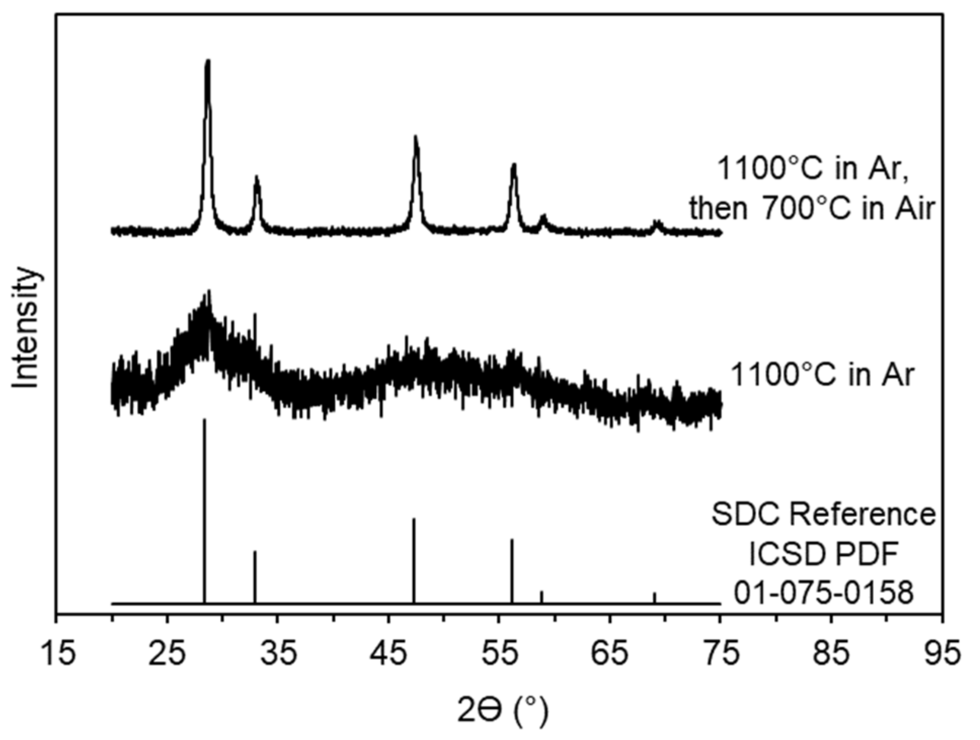
Powder x-ray diffraction (PXRD) patterns of both the sintered and calcined SDC-Glucose hybrid materials are shown in Figure 1. The peaks of the sintered material are very broad, which is characteristic of an amorphous phase. The calcined material pattern matches the SDC reference pattern, indicating that a pure crystalline nSDC phase was produced. The crystallite size of the nSDC, estimated with the Scherrer Equation, was ~15 nm. This value is consistent with our previous works in which we prepared other SOFC nanomaterials using the in situ carbon templating method [26,27,28,30].
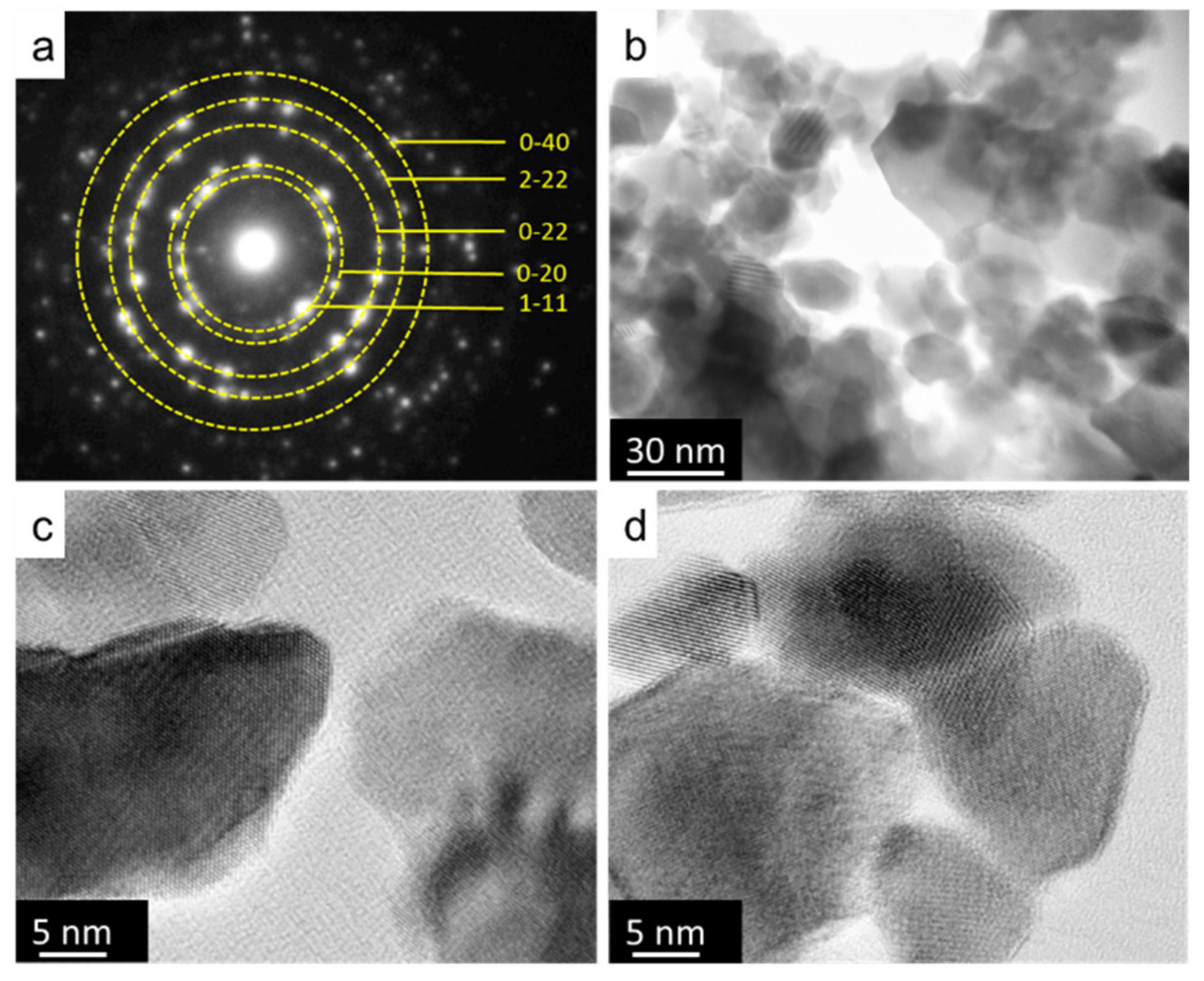
Transmission electron microscopy (TEM) results, shown in Figure 2, provide additional information regarding the crystallinity and morphology of the nSDC particles. The diffraction pattern shown in Figure 2a confirms that a pure crystalline SDC cubic structure formed, consistent with our PXRD results. The TEM micrographs, shown in Figure 2b–d, indicate that the particle size of the nSDC ranged between 10 nm and 25 nm. Assuming particles of spherical geometry and equal size, 10 nm and 25 nm SDC particles correspond to specific surface areas of 35 m2·g−1 and 85 m2·g−1, respectively. The particle sizes observed by TEM and the crystallite sizes estimated with PXRD are within the same range, indicating that the nSDC particles are not polycrystalline.
2.2. Symmetrical Cell Electrochemical Analysis
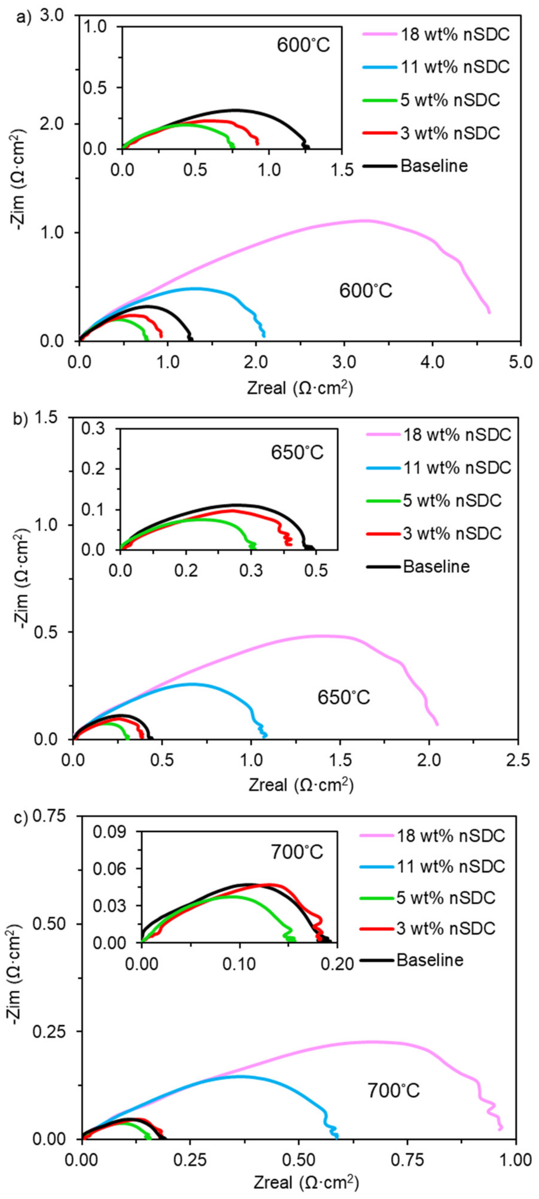
The electrocatalytic activities of LSCF-SDC cathodes containing various amounts of nSDC were evaluated with symmetrical cells. Figure 3 shows Nyquist plots for symmetrical cells with 0 wt%, 3 wt%, 5 wt%, 11 wt%, and 18 wt% nSDC. The high frequency intercept with the abscissa is at 0 Ω·cm2 and the low frequency intercept with the abscissa represents the total cathode polarization resistance. Compared to the baseline cell (0 wt% nSDC), the addition of 3 wt% nSDC decreased the polarization resistance at 600 °C by 28% from 1.27 Ω·cm2 to 0.92 Ω·cm2. Increasing the nSDC concentration to 5 wt% further decreased the polarization resistance to 0.75 Ω·cm2, which is 41% lower than the baseline cell. However, higher loadings of nSDC resulted in worse electrocatalytic activity. The polarization resistance was 2.09 Ω·cm2, 1.6 times higher than baseline, for 11 wt% nSDC and 4.64 Ω·cm2, 3.7 times higher than baseline, for 18 wt% nSDC.
Similar trends were observed at 650 °C and 700 °C; however, the percent improvement in polarization resistance for 3 wt% and 5 wt% nSDC lessened with increasing temperature (Figure 3b,c). At 650 °C, the polarization resistance was reduced, relative to baseline, by 11% and 30% for the 3 wt% and 5 wt% nSDC cells, respectively. At 700 °C, the 3 wt% nSDC cell was nearly the same as the baseline cell and the 5 wt% nSDC showed a 21% reduction, 0.15 Ω·cm2 compared to 0.19 Ω·cm2. For higher nSDC loadings, the percent difference in polarization resistance increased with increasing temperature. For 11 wt% nSDC, the resistance was a factor of 2.4 and 3.1 higher at 650 °C and 700 °C, respectively. The 18 wt% nSDC resistance was 4.7 times higher than the baseline at 650 °C and 5.1 times higher at 700 °C.
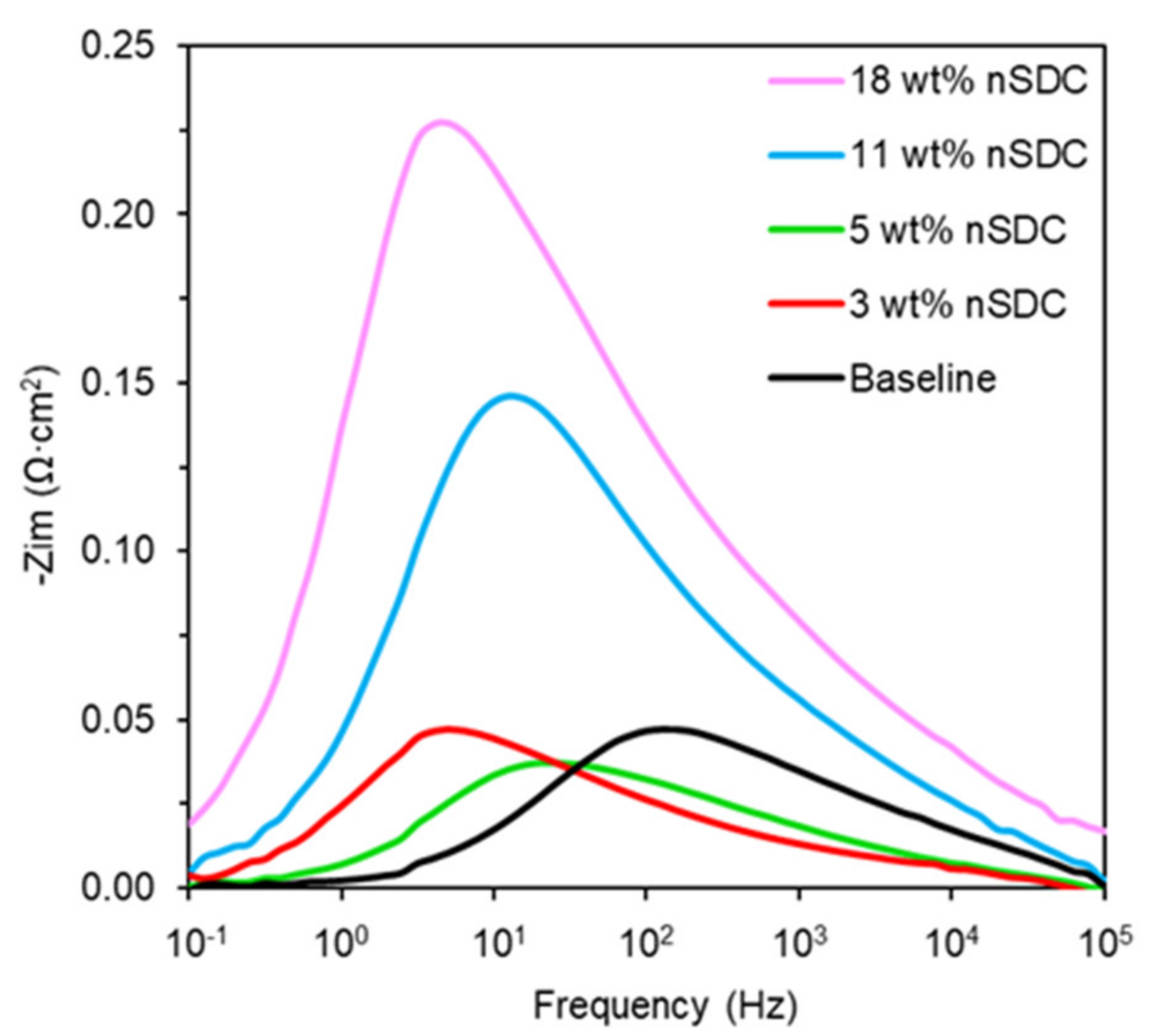
Bode plots of the symmetrical cells provide further insights into the impact of nSDC on the cathode electrochemical processes (Figure 4). Data is only shown for 700 °C because the peak frequencies are essentially the same over the 600 °C–700 °C range. All symmetrical cells show one dominant peak between 5 Hz and 125 Hz, which is considered an intermediate frequency range for SOFC electrodes. The literature attributes cathode processes in the intermediate range to oxygen adsorption kinetics, which include oxygen adsorption, oxygen dissociation, and surface charge transport steps [31,32,33]. Typically, improving cathode electrocatalytic activity and polarization resistance shifts the Bode plot peak to a higher frequency, corresponding to a faster relaxation time. However, lower peak frequencies were observed for the 3 wt% nSDC and 5 wt% nSDC cells even though their polarization resistances were lower than the baseline. A similar trend was previously observed for lanthanum strontium ferrite-yttria stabilized zirconia (LSF-YSZ) cathodes integrated with YSZ nanoparticles [27]. This implies that the shift to slower relaxation times is due to how the in situ carbon templated nanomaterials interact with the coarse LSCF and SDC particles in the cathode.
2.3. Morphological Analysis
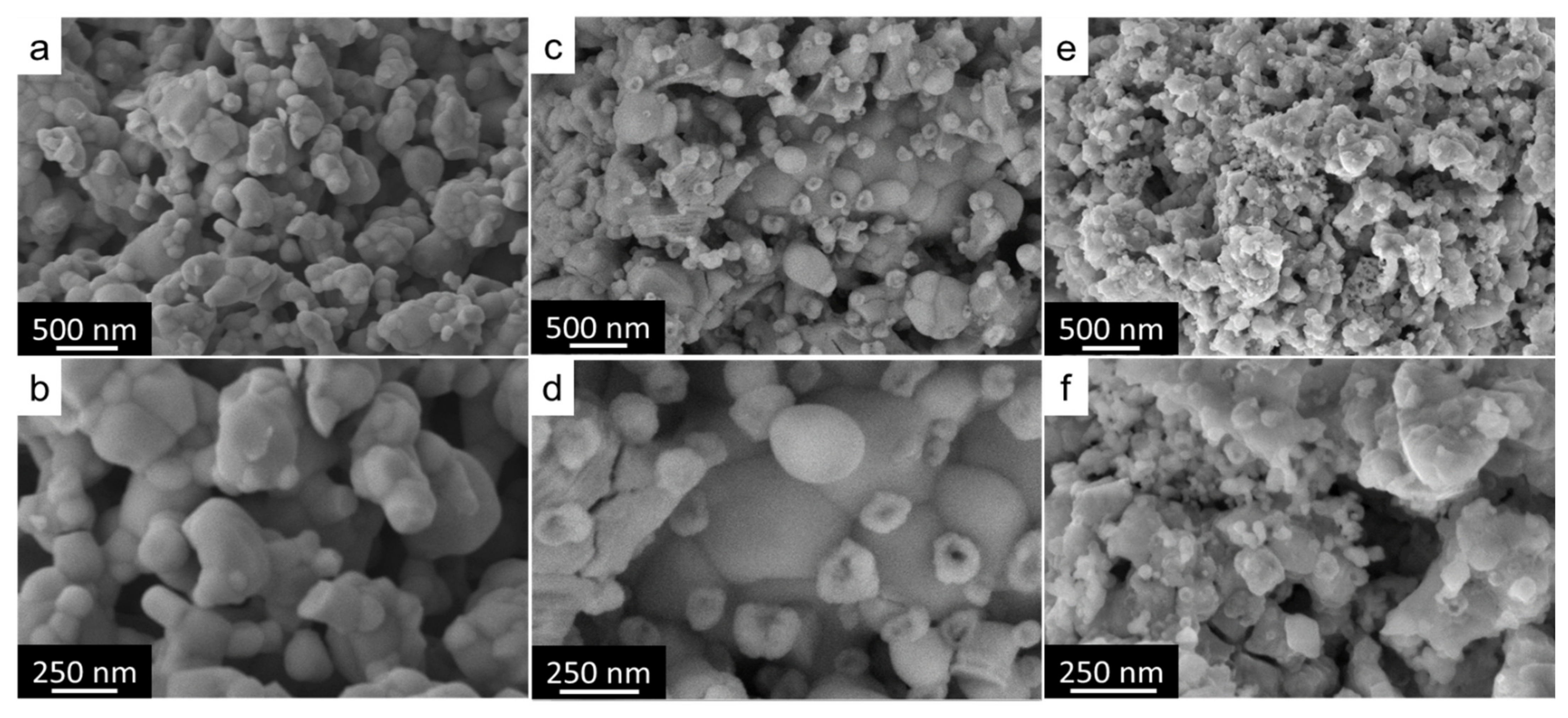
The symmetrical cell results demonstrate that low loadings of nSDC improve polarization resistance while high loadings of nSDC worsen it. To better understand this trend, scanning electron microscopy (SEM) images of LSCF-SDC-nSDC with 0 wt%, 5 wt%, and 18 wt% nSDC were collected (Figure 5). The baseline composite is typical of a traditionally sintered LSCF-SDC electrode, comprising sintered particles with a characteristic size of ~400 nm with some ~100 nm nodules (Figure 5a,b). The 5 wt% nSDC composites (Figure 5c,d) also formed a sintered network of ~400 nm particles; however, the morphology also shows particles in the 70 nm to 200 nm range that do not appear to be well sintered to the coarse particles. In addition, these smaller particles have an irregular surface morphology. Although limitations with the SEM instrumentation did not allow us to image the surface morphology of these particles in greater detail, it is likely that the specific surface area of these particles are considerably higher than the 100 nm nodules observed in the baseline composite. Finally, SEM images of the 18 wt% nSDC composites are shown in Figure 5e,f. Similar to the 5 wt% nSDC composite, sintered coarse particles and ~100 nm particles with an irregular surface morphology were observed. In addition, a high concentration of particle features in the 20 nm–50 nm range was observed.
The morphologies observed by SEM help explain the symmetrical cell results. First, the high concentration of 20 nm–50 nm particles in the 18 wt% nSDC composite appear to compromise electrode particle connectivity. A TPB site in the cathode can only be electrocatalytically active if the SDC at that site is part of a percolated network of SDC particles spanning the electrode and the LSCF at that site is part of a percolated network of LSCF particles that also span the electrode. The morphology observed in Figure 5e,f is likely weakly connected or even isolated particle networks, which would result in a lower density of TPB sites, a lower active area in the cathode, and the higher polarization resistance observed in symmetrical cells. Furthermore, the cathode polarization resistance for symmetrical cells with the higher nSDC loadings worsened relative to the baseline cell with increasing temperature. Here we propose that the decline in electrochemical activity with increasing temperature was likely caused by coarsening of the 20 nm–50 nm particles. Coarsening of these nanoparticles would further weaken particle connectivity, further lower the density of TPB sites and active cathode area, and further increase the polarization resistance.
Unlike the 18 wt% nSDC morphology, the 5 wt% nSDC composite maintained a well-connected network of coarse particles with smaller, higher surface area particles decorating the surface of that coarse, porous scaffold structure. Interestingly, this morphology mimics the morphology of an infiltrated cell. In this case, the coarse particles form percolated networks, similar to the co-sintered baseline cell; however, the additional nanoparticles decorate the surface of the coarse particles further increasing the density of TPB sites and active area of the cathode. This is similar to how infiltrated electrode structures form a high density of active TPB sites. There is one difference between our novel electrode structures and infiltrated electrode structures. Typically, infiltrated electrodes are prepared by infiltrating the electronically conductive phase into a porous scaffold of an oxygen ion conducting material, which is electronically insulating. Thus, the infiltrated phase itself must form a percolated network that spans the electrode to form active TPB sites. In the case of our electrode structure, the nSDC particles do not necessarily have to form a percolated network among themselves to become active TPB sites because the coarse particles consist of both SDC and LSCF phases, providing both oxygen ion and electronic conductivity. The key takeaway from the symmetrical cell results and SEM images is that high loadings of nSDC compromise particle connectivity and, in turn, the cathode active area, whereas low loadings of nSDC enhance the density of active sites without compromising particle connectivity.
2.4. Infiltrated Symmetrical Cell
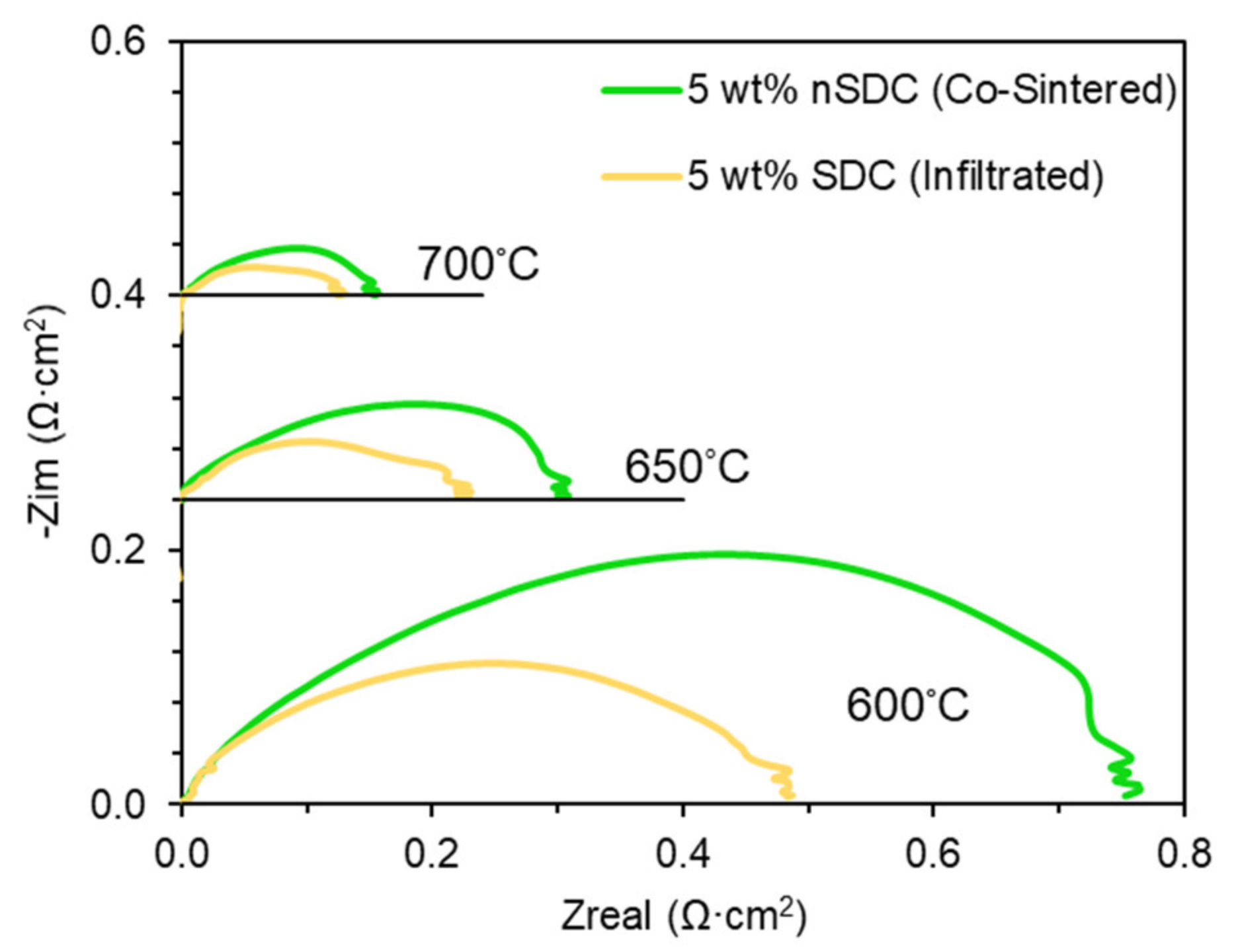
Upon establishing that the best cathode polarization resistance was obtained with the 5 wt% nSDC symmetrical cell, the electrochemical behavior of a symmetrical cell infiltrated with 5 wt% SDC was assessed for comparison (Figure 6). The figure compares Nyquist plots of both cells at 600 °C, 650 °C, and 700 °C. The polarization resistance of the infiltrated cell was lower than the co-sintered LSCF-SDC-nSDC cell. However, the difference in polarization resistance lessened with increasing temperature, changing from a difference of 37% at 600 °C to 21% at 650 °C and 13% at 700 °C. The diminishing improvement with increasing temperature suggests that the promotive effect of the infiltrated cell is not stable. It is important to note that the infiltrated SDC was thermally processed at 450 °C in air, which is typical for infiltrated cells, and, hence, it is likely that the infiltrated SDC particles underwent morphological changes at these higher operating temperatures. The data suggests that long-term degradation studies are needed to better understand the relative performance of these two types of cells.
2.5. Fuel Cell Electrochemical Analysis
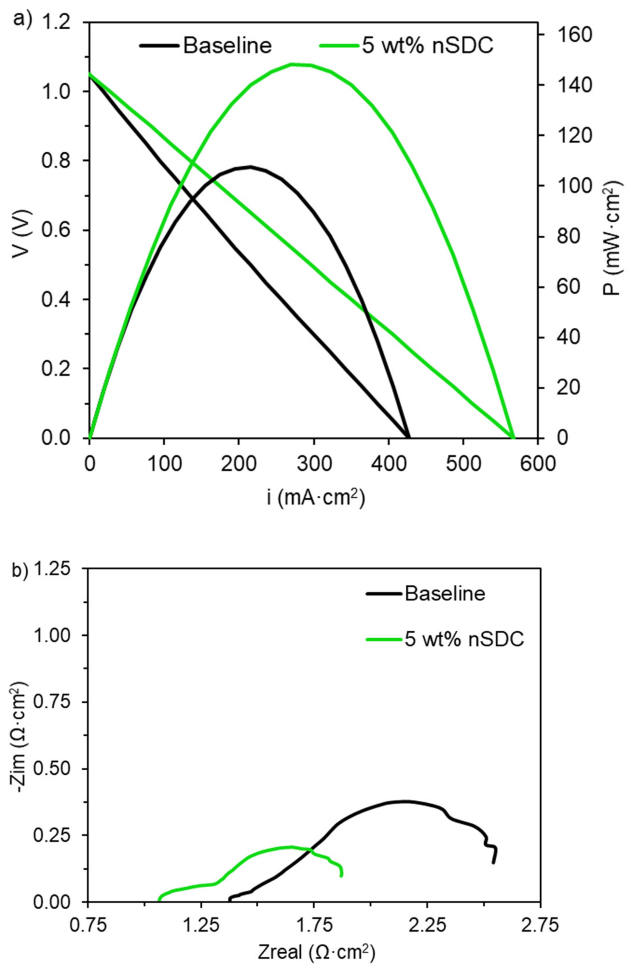
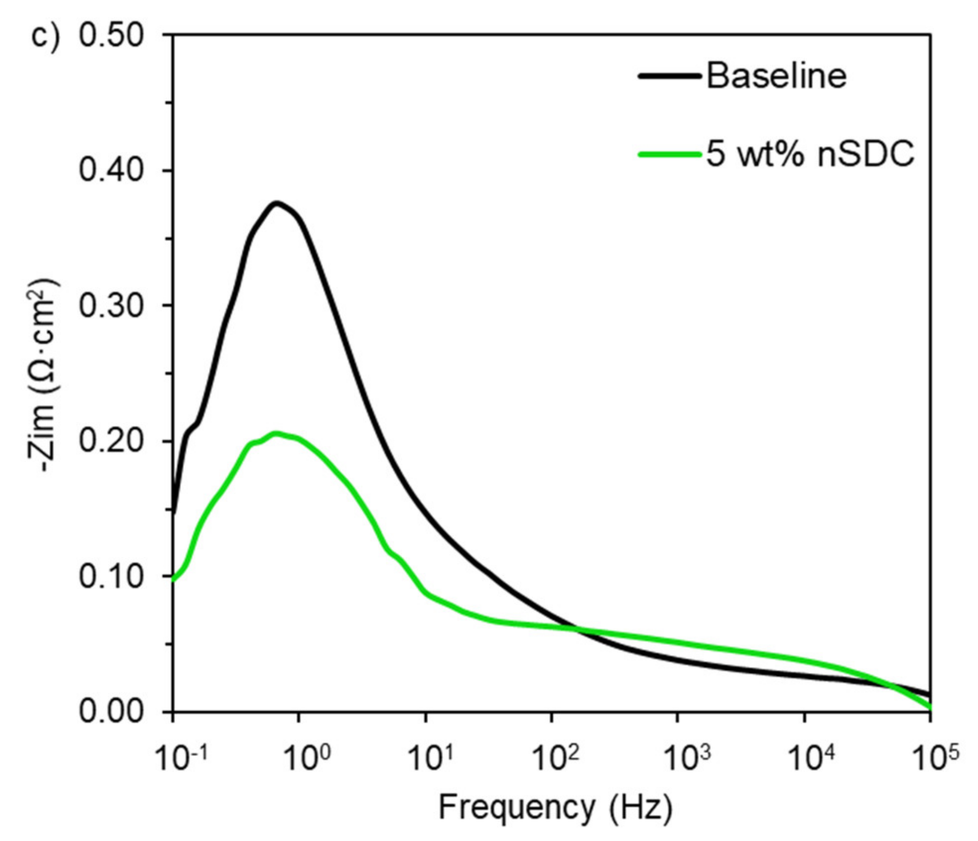
In addition to symmetrical cell studies, the electrochemical behavior of a fuel cell with a co-sintered 5 wt% nSDC cathode was compared to a baseline fuel cell (Figure 7). As shown in Figure 7a, the maximum power density of the 5 wt% nSDC cell was 38% higher than the baseline with a value of 148 mW·cm2 compared to 108 mW·cm2. Nyquist plots shown in Figure 7b indicate that the total polarization resistance of the 5 wt% nSDC fuel cell was 31% lower than the baseline, 0.80 Ω·cm2 compared to 1.16 Ω·cm2. The improvement in polarization resistance with the addition of nSDC is consistent with the symmetrical cell results; however, the polarization resistance values for both fuel cells are several times higher than the symmetrical cell polarization resistance. This suggests fuel cell polarization resistance under current load has a different rate-determining process compared to symmetrical cells, which were measured at open circuit voltage. Indeed, the fuel cell Nyquist plots in Figure 7b show a dominant arc in the low frequency range that was not observed with symmetrical cells. Bode plots, in Figure 7c, show that the rate-limiting fuel cell process has a characteristic frequency of 0.8 Hz for both fuel cells, which is considerably lower than the characteristic frequencies observed for symmetrical cells and is typically assigned to gas-phase mass transport limitations [34,35,36,37,38]. Thus, the primary rate-determining fuel cell process can be attributed to gas-phase mass transport.
Although gas-phase mass transport dominated the fuel cell impedance spectra, there was a significant improvement in the ohmic, serial resistance of the 5 wt% nSDC fuel cell compared to the baseline. Ohmic resistance values correspond to the high frequency intercept with the abscissa in the Nyquist plots. The ohmic resistance of the 5 wt% nSDC cell was 23% lower, 1.06 Ω·cm2 compared to 1.38 Ω·cm2 for the baseline fuel cell. The anode and electrolyte were identical for both fuel cells, thus, the improvement in both polarization and ohmic resistance can be attributed to differences in the cathode. Exclusive improvement in polarization resistance would indicate an improvement in the electrocatalytic activity of the cathode and exclusive improvement in the ohmic resistance would indicate an improvement in electronic or oxygen ion conductivity within the cathode. The fact that both the polarization and ohmic resistances improved to a similar degree suggests that the total electrocatalytically active area of the cathode increased with the addition of 5 wt% nSDC. In other words, the addition of SDC nanoparticles improved both electrocatalytic activity and charge transport by increasing the active area of the cathode.
Overall, this work proves the concept that nanoparticles can be integrated into SOFC electrodes and enhance cell performance by co-sintering. We have previously shown that in situ carbon templating is applicable to a large number of SOFC materials [24,25,26]. Hence, this work provides a procedure that could be used to integrate nanoparticles into a variety of co-sintered SOFC electrodes. Regarding low temperature SOFC operation, researchers have developed electrolyte materials, such as Dy2O3–WO3 co-stabilized Bi2O3 (DWSB) [8,39,40] and lanthanum strontium gallium magnesium oxide (LSGM) [41,42], with better low-temperature oxygen ion conductivity than the state-of-the-art YSZ or SDC. Moreover, a growing number of researchers are considering proton-conducting electrolytes such as doped BaZrO3 and doped BaCeO3 for low temperature SOFC operations owing to the low resistance associated with proton conduction in comparison to oxygen ion conduction [43,44,45]. Given the large range of materials we have successfully processed by the in situ carbon templating method, it is likely that this method can be applied to these alternative materials and their co-sintered electrodes. Improving the performance of such electrodes would be a major step towards realizing low-temperature SOFCs.
3. Materials and Methods
3.1. Material Preparation
The SDC-Glucose inorganic-organic hybrid material was prepared using our previously reported procedures [24,25,26,27,28,29]. Ce(NO3)3·6H2O (99.5%, Alfa Aesar, Haverhill, MA, USA), Sm(NO3)3·6H2O (99.9%, Alfa Aesar, Haverhill, MA, USA), and glucose (100.0%, USBiological, Salem, MA, USA) were dissolved in deionized water in a 4:1:475:22.5 Ce:Sm:H2O:Glucose molar ratio with magnetic stirring. The solution was then heated at 120 °C until a viscous material formed. Then, the viscous material was heated to 1100 °C under an argon atmosphere (G01 AR300, Arc3, Dunn, NC, USA) flowing at a rate of 750 mL·min−1. The temperature was increased from ambient temperature to 850 °C at 5 °C·min−1 and from 850 °C to 1100 °C at 2 °C·min−1, held at 1100 °C for 2 h, and then decreased to 850 °C and ambient temperature at the same respective ramp rates. This process produced carbon-templated SDC nanoparticles (nSDC-C). Subsequent calcination of the nSDC-C at 700 °C in air produced SDC nanoparticles (nSDC).
3.2. Material Characterization
Powder x-ray diffraction (PXRD) was conducted on a nSDC-C sample before and after calcination in air at 700 °C for 2 h. The PXRD patterns were collected with a Bruker D2 Phaser X-ray diffractometer (Bruker AXS LLC, Madison, WI, USA) with CuKα radiation, a 20–75° 2θ range, a 0.03° increment, and a 0.3 s time steps. High-resolution transmission electron microscopy (HR-TEM), electron diffraction, and diffraction contrast were performed on an nSDC sample with a JEM-2100 (JEOL Ltd., Peabody, MA, USA) at 200 kV.
3.3. Symmetrical and Fuel Cell Fabrication
Cathode inks were prepared by physically mixing nSDC-C, commercial SDC (SDC20-TC, Nexceris, Lewis Center, OH, USA), commercial LSCF (LSCF-HP, Nexceris, Lewis Center, OH, USA), and an ink vehicle (VEH, Nexceris, Lewis Center, OH, USA). Five cathode inks were prepared, each with a different concentration of nSDC: 0 wt% (baseline), 3 wt%, 5 wt%, 11 wt%, and 18 wt%. For symmetrical cells, SDC electrolytes were prepared by sintering pressed powder at 1400 °C in air for 5 h. The diameter and thickness of the resulting pellets were 13.5 mm and 0.6 mm, respectively. A film of cathode ink was then applied symmetrically to each side of the electrolyte. The symmetrical cells were sintered in argon at 1000 °C (2 °C·min−1) for 2 h and subsequently calcined in air at 700 °C (2 °C·min−1) for 2 h to remove the carbon templates from the cathodes. The baseline cell was sintered directly in air at 1000 °C. For comparison, a different baseline cell was infiltrated with 5 wt% SDC using the traditional infiltration technique. The electrodes were filled with a solution of Ce(NO3)3·6H2O, Sm(NO3)3·6H2O, and citric acid (CA, ≥99.5%, USBiological, Salem, MA, USA) in a Ce:Sm:CA molar ratio of 0.8:0.2:1 and heated in air at 450 °C (2 °C·min−1) for 2 h to produce the SDC phase. In all cases, the electrodes’ thickness and effective area were ~20 μm and 0.32 cm2, respectively.
For fuel cells, ~250 μm thick yttria stabilized zirconia (YSZ) substrates (YSZ8-2.0, Nexceris, Lewis Center, OH, USA) coated with ~20 μm SDC barrier layers were used as electrolytes. The SDC barrier layers were screen-printed onto the YSZ substrates and sintered at 1400 °C (2 °C·min−1) for 5 h in air. The anode ink (66 wt% NiO–34 wt% YSZ, 77–73 wt% solids loading, Nexceris, Lewis Center, OH, USA) was applied onto one side of the electrolyte and sintered at 1300 °C for 2 h in air. The cathode inks were subsequently applied onto the opposite side of the electrolyte and sintered in argon at 1000 °C for 2 h followed by calcination in air at 700 °C for 2 h to remove the carbon template. The baseline cell was sintered directly in air at 1000 °C. The final thicknesses and cross sectional areas were ~100 μm and 0.71 cm2 for the anodes and ~50 μm and 0.32 cm2 for the cathodes.
3.4. Symmetrical and Fuel Cell Characterization
Electrochemical performance was investigated with electrochemical impedance spectroscopy (EIS) and current-voltage (I-V) measurements using a Gamry Interface 5000E potentiostat (Gamry Instruments, Warminster, PA) with four probes. Silver ink and silver wires were applied onto the electrodes for current collection. The test conditions for symmetrical and fuel cells are summarized in Table 1. EIS experiments were conducted in potentiostatic mode with a dc voltage of 0 V (symmetrical cells) and 0.7 V (fuel cells), 20 mV ac perturbation, and 105–10−1 Hz frequency range. The symmetrical cells were tested in air at 600 °C, 650 °C, and 700 °C and the impedance values were divided by two to account for the two electrodes. Fuel cell experiments were conducted at 700 °C with humidified hydrogen (3% H2O) flowing to the anode at a rate of 100 mL·min−1 and the cathode was exposed to air. Cathode composite morphology was examined with scanning electron microscopy (SEM) using a ZEISS GeminiSEM 300 (Carl Zeiss Microscopy LLC, White Plains, NY, USA).
4. Conclusions
LSCF-SDC cathodes comprising SDC nanoparticles were realized by a simple co-sintering process. Symmetrical cell data indicated that high concentrations of SDC nanoparticles (>10 wt%) worsened polarization resistance while low concentrations of SDC nanoparticles (≤5 wt%) improved it. The best symmetrical cell performance was achieved with a nSDC loading of 5 wt%. Regarding fuel cell performance, the 5 wt% nSDC cathode loading increased the maximum power density by 38% due to a significant reduction in both the polarization and ohmic resistance. The results bring to light a novel procedure for creating and preserving nanoparticles during SOFC electrode co-sintering, which improves electrode activity.
Author Contributions
Conceptualization, S.P.M. and M.D.G.; Methodology, S.P.M. and M.D.G.; Formal Analysis & Investigation, S.P.M.; Writing—Original Draft Preparation, S.P.M.; Writing—Review & Editing, S.P.M. and M.D.G.; Project Administration, M.D.G.; Funding Acquisition, M.D.G. All authors have read and agreed to the published version of the manuscript.
Funding
This research was funded by the National Science Foundation (NSF) Faculty Early Career Development (CAREER) award (CMMI-1651186) and the National Energy Technology Laboratory’s ongoing research under the RSS Contract 89243318CFE000003.
Data Availability Statement
Acknowledgments
We would like to thank Xueyan Song for assistance with collection and analysis of TEM data.
Conflicts of Interest
The authors declare no conflict of interest.
Disclaimer
This project was funded by the Department of Energy, National Energy Technology Laboratory, an agency of the United States Government, through a support contract with Leidos Research Support Team (LRST). Neither the United States Government nor any agency thereof, nor any of their employees, nor LRST, nor any of their employees, makes any warranty, expressed or implied, or assumes any legal liability or responsibility for the accuracy, completeness, or usefulness of any information, apparatus, product, or process disclosed, or represents that its use would not infringe privately owned rights. Reference herein to any specific commercial product, process, or service by trade name, trademark, manufacturer, or otherwise, does not necessarily constitute or imply its endorsement, recommendation, or favoring by the United States Government or any agency thereof. The views and opinions of authors expressed herein do not necessarily state or reflect those of the United States Government or any agency thereof.
References
- Mogensen, M.; Skaarup, S. Kinetic and Geometric Aspects of Solid Oxide Fuel Cell Electrodes. Solid State Ion. 1996, 86–88, 1151–1160. [Google Scholar] [CrossRef]
- Steele, B.C.H.; Hori, K.M.; Uchino, S. Kinetic Parameters Influencing the Performance of IT-SOFC Composite Electrodes. Solid State Ion. 2000, 135, 445–450. [Google Scholar] [CrossRef]
- Haile, S.M. Fuel Cell Materials and Components. Acta Mater. 2003, 51, 5981–6000. [Google Scholar] [CrossRef]
- Ji, S.; Chang, I.; Lee, Y.H.; Park, J.; Paek, J.Y.; Lee, M.H.; Cha, S.W. Fabrication of low-temperature solid oxide fuel cells with a nanothin protective layer by atomic layer deposition. Nanoscale Res. Lett. 2013, 8, 48. [Google Scholar] [CrossRef] [PubMed] [Green Version]
- Kim, Y.B.; Hus, C.-M.; Connor, S.T.; Gur, T.M.; Cui, Y.; Prinz, F.B. Nanopore Patterned Pt Array Electrodes for Triple Phase Boundary Study in Low Temperature SOFC. J. Electrochem. Soc. 2010, 157, B1269–B1274. [Google Scholar] [CrossRef] [Green Version]
- Ji, S.; Chang, I.; Chao, G.Y.; Lee, Y.H.; Shim, J.H.; Cha, S.W. Application of dense nano-thin platinum films for low-temperature solid oxide fuel cells by atomic layer deposition. Int. J. Hydrogen Energy 2014, 39, 12402–12408. [Google Scholar] [CrossRef]
- Egger, A.; Bucher, E.; Yang, M.; Sitte, W. Comparison of Oxygen Exchange Kinetics of the IT-SOFC Cathode Materials La0.5Sr0.5CoO3-δ and La0.6Sr0.4CoO3-δ. Solid State Ion. 2012, 225, 55–60. [Google Scholar] [CrossRef]
- Wachsman, E.D.; Lee, K.T. Lowering the Temperature of Solid Oxide Fuel Cells. Science 2011, 334, 935–939. [Google Scholar] [CrossRef]
- Gao, Z.; Mogni, L.V.; Miller, E.C.; Railsback, J.G.; Barnett, S.A. A Perspective on Low-Temperature Solid Oxide Fuel Cells. Energy Environ. Sci. 2016, 9, 1602–1644. [Google Scholar] [CrossRef]
- Yang, G.; Su, C.; Shi, H.; Zhu, Y.; Song, Y.; Zhou, W.; Shao, Z. Toward Reducing the Operation Temperature of Solid Oxide Fuel Cells: Our Past 15 Years of Efforts in Cathode Development. Energy Fuels 2020, 34, 15169–15194. [Google Scholar] [CrossRef]
- Kilner, J.A.; Burriel, M. Materials for Intermediate-Temperature Solid-Oxide Fuel Cells. Annu. Rev. Mater. Res. 2014, 44, 365–393. [Google Scholar] [CrossRef]
- Fabbri, E.; Bi, L.; Pergolesi, D.; Traversa, E. Towards the Next Generation of Solid Oxide Fuel Cells Operating Below 600 °C with Chemically Stable Proton-Conducting Electrolytes. Adv. Mater. 2012, 24, 195–208. [Google Scholar] [CrossRef] [PubMed]
- Vohs, J.M.; Gorte, R.J. High-Performance SOFC Cathodes Prepared by Infiltration. Adv. Mater. 2009, 21, 943–956. [Google Scholar] [CrossRef]
- Jiang, S.P. A Review of Wet Impregnation—An Alternative Method for the Fabrication of High Performance and Nano-structured Electrodes of Solid Oxide Fuel Cells. Mater. Sci. Eng. A 2006, 418, 199–210. [Google Scholar] [CrossRef]
- Jiang, Z.; Xia, C.; Chen, F. Nano-structured Composite Cathodes for Intermediate-Temperature Solid Oxide Fuel Cells via an Infiltration/Impregnation Technique. Electrochim. Acta 2010, 55, 3595–3605. [Google Scholar] [CrossRef]
- He, H.; Huang, Y.; Regal, J.; Boaro, M.; Vohs, J.M.; Gorte, R.J. Low-Temperature Fabrication of Oxide Composites for Solid-Oxide Fuel Cells. J. Am. Ceram. Soc. 2004, 87, 331–336. [Google Scholar] [CrossRef]
- Ding, D.; Li, X.; Lai, S.Y.; Gerdes, K.; Liu, M. Enhancing SOFC Cathode Performance by Surface Modification through Infiltration. Energy Environ. Sci. 2014, 7, 552–575. [Google Scholar] [CrossRef]
- Shah, M.; Barnett, S.A. Solid Oxide Fuel Cell Cathodes by Infiltration of La0.6Sr0.4Co0.2Fe0.8O3-δ into Gd-Doped Ceria. Solid State Ion. 2008, 179, 2059–2064. [Google Scholar] [CrossRef]
- Synodis, M.J.; Porter, C.L.; Vo, N.M.; Reszka, A.J.L.; Gross, M.D.; Snyder, R.C. A Model to Predict Percolation Threshold and Effective Conductivity of Infiltrated Electrodes for Solid Oxide Fuel Cells. J. Electrochem. Soc. 2013, 160, F1216–F1224. [Google Scholar] [CrossRef]
- Reszka, A.J.L.; Snyder, R.C.; Gross, M.D. Insights into the Design of SOFC Infiltrated Electrodes with Optimized Active TPB Density via Mechanistic Modeling. J. Electrochem. Soc. 2014, 161, F1176–F1183. [Google Scholar] [CrossRef]
- Kim, J.D.; Kim, G.D.; Moon, J.W.; Park, Y.I.; Lee, W.H.; Kobayashi, K.; Nagai, M.; Kim, C.E. Characterization of LSM-YSZ Composite Electrode by AC Impedance Spectroscopy. Solid State Ion. 2001, 143, 379–389. [Google Scholar] [CrossRef]
- Choi, J.H.; Jang, J.H.; Oh, S.M. Microstructure and Cathodic Performance of La0.9Sr0.1MnO3/Yttria-Stabilized-Zirconia Composite Electrodes. Electrochim. Acta 2001, 46, 867–874. [Google Scholar] [CrossRef]
- Matsuzaki, Y.; Yasuda, I. Electrochemical properties of reduced-temperature SOFCs with mixed ionic–electronic conductors in electrodes and/or interlayers. Solid State Ion. 2002, 152–153, 463–468. [Google Scholar] [CrossRef]
- Muhoza, S.P.; Barrett, T.E.; Cottam, M.A.; Soll, S.E.; Yuce, M.D.; Prathab, V.S.; Hambright, S.K.; Rezazad, M.; Racchi, O.; Gross, M.D. High Surface Area SOFC Electrode Materials Prepared at Traditional Sintering Temperatures. J. Electrochem. Soc. 2018, 165, F46–F54. [Google Scholar] [CrossRef]
- Muhoza, S.P.; Barrett, T.E.; Soll, S.E.; Gross, M.D. Nanostructured SOFC Electrode Scaffolds Prepared via High Temperature in situ Carbon Templating of Hybrid Materials. ECS Trans. 2017, 78, 1407–1416. [Google Scholar] [CrossRef]
- Muhoza, S.P.; Cottam, M.A.; Gross, M.D. High Temperatures Fabrication of Nanostructured Yttria-Stabilized-Zirconia (YSZ) Scaffolds by In Situ Carbon Templating Xerogels. J. Vis. Exp. 2017, 122, e55500. [Google Scholar] [CrossRef] [PubMed]
- Muhoza, S.P.; McCormack, A.; Garrett, R.W.; Yuce, M.D.; Prathab, V.S.; Hambright, S.K.; Cottam, M.A.; Gross, M.D. Processing Nano-YSZ in Solid Oxide Fuel Cells: The Effect of Sintering Atmosphere on Thermochemical Stability. J. Electrochem. Soc. 2019, 166, F53–F58. [Google Scholar] [CrossRef]
- Muhoza, S.P.; Taylor, T.H.; Song, X.; Gross, M.D. The Impact of Sintering Atmosphere and Temperature on the Phase Evolution of High Surface Area LSCF Prepared by In Situ Carbon Templating. J. Electrochem. Soc. 2021, 168, 034519. [Google Scholar] [CrossRef]
- Cottam, M.; Muhoza, S.; Gross, M.D. Preserving Nanomorphology in YSZ Scaffolds at High Temperatures via In Situ Carbon Templating of Hybrid Materials. J. Am. Ceram. Soc. 2016, 99, 2625–2631. [Google Scholar] [CrossRef]
- Muhoza, S.P.; Lee, S.; Song, X.; Guan, B.; Yang, T.; Gross, M.D. Enhancing Activity, Charge Transport, Power Production, and Stability of Commercial Solid Oxide Fuel Cells with Yttria-Stabilized Zirconia Nanoparticles. J. Electrochem. Soc. 2020, 167, 024517. [Google Scholar] [CrossRef]
- Chen, Y.; Bu, Y.; Zhang, Y.; Yan, R.; Ding, D.; Zhao, B.; Yoo, S.; Dang, D.; Hu, R.; Yang, C.; et al. A Highly Efficient and Robust Nanofiber Cathode for Solid Oxide Fuel Cells. Adv. Energy Mater. 2017, 7, 1601890. [Google Scholar] [CrossRef]
- Xu, H.; Zhang, H.; Chu, A. An Investigation of Oxygen Reduction Mechanism in Nano-sized LSCF-SDC Composite Cathodes. Int. J. Hydrogen Energy 2016, 41, 22415–22421. [Google Scholar] [CrossRef] [Green Version]
- Xu, X.; Jiang, Z.; Fan, X.; Xia, C. LSM-SDC Electrodes Fabricated with an Ion-Impregnating Process for SOFCs with Doped Ceria Electrolytes. Solid State Ion. 2006, 177, 2113–2117. [Google Scholar] [CrossRef]
- Endler, C.; Leonide, A.; Weber, A.; Tietz, F.; Ivers-Tiffée, E. Time-Dependent Electrode Performance Changes in Intermediate Temperature Solid Oxide Fuel Cells. J. Electrochem. Soc. 2010, 157, B292–B298. [Google Scholar] [CrossRef]
- Kornely, M.; Menzler, N.H.; Weber, A.; Ivers-Tiffée, E. Degradation of a High Performance SOFC Cathode by Cr-Poisoning at OCV Conditions. Fuel Cells 2013, 13, 506–510. [Google Scholar] [CrossRef]
- Weber, A.; Szász, J.; Dierickx, S.; Endler-Schuck, C.; Ivers-Tiffée, E. Accelerated Lifetime Tests for SOFCs. ECS Trans. 2015, 68, 1953–1960. [Google Scholar] [CrossRef]
- Wuillemin, Z.; Antonetti, Y.; Beetschen, C.; Millioud, O.; Ceschini, S.; Madi, H.; Van herle, J. Local Activation and Degradation of Electrochemical Processes in a SOFC. ECS Trans. 2013, 57, 561–570. [Google Scholar] [CrossRef]
- Caliandro, P.; Nakajo, A.; Diethelm, S.; Van herle, J. Model-assisted identification of solid oxide cell elementary processes by electrochemical impedance spectroscopy measurements. J. Power Sources 2019, 436, 226838. [Google Scholar] [CrossRef]
- Jung, D.W.; Duncan, K.L.; Wachsman, E.D. Effect of Total Dopant Concentration and Dopant Ratio on Conductivity of (DyO1.5)x-(WO3)y-(BiO1.5)1-x-y. Acta Mater. 2010, 58, 355–363. [Google Scholar] [CrossRef]
- Wachsman, E.; Ishihara, T.; Kilner, J. Low-Temperature Solid-Oxide Fuel Cells. MRS Bull. 2014, 39, 773–779. [Google Scholar] [CrossRef] [Green Version]
- Ishihara, T.; Matsuda, H.; Takita, Y. Effects of Rare Earth Cations Doped for La Site on the Oxide Ionic Conductivity of LaGaO3-based Perovskite Type Oxide. Solid State Ion. 1995, 79, 147–151. [Google Scholar] [CrossRef]
- Huang, K.; Tichy, R.; Goodenough, J.B. Superior Perovskite Oxide-Ion Conductor; Strontium- and Magnesium-Doped LaGaO3: III, Performance Tests of Single Ceramic Fuel Cells. J. Am. Ceram. Soc. 1998, 81, 2581–2585. [Google Scholar] [CrossRef]
- Zhang, W.; Hu, Y.H. Progress in Proton-Conducting Oxides as Electrolytes for Low-Temperature Solid Oxide Fuel Cells: From Materials to Devices. Energy Sci. Eng. 2021, 9, 984–1011. [Google Scholar] [CrossRef]
- Lin, Y.; Ran, R.; Zheng, Y.; Shao, Z.; Jin, W.; Xu, N.; Ahn, J. Evaluation of Ba0.5Sr0.5Co0.8Fe0.2O3-δ as a Potential Cathode for an Anode-Supported Proton-Conducting Solid Oxide Fuel Cell. J. Power Sources 2008, 180, 15–22. [Google Scholar] [CrossRef]
- Cervera, R.B.; Oyama, Y.; Miyoshi, S.; Kobayashi, K.; Yagi, T.; Yamaguchi, S. Structural Study and Proton Transport of Bulk Nanograined Y-Doped BaZrO3 Oxide Protonics Materials. Solid State Ion. 2008, 179, 236–242. [Google Scholar] [CrossRef]
Figure 1.
Powder x-ray diffraction patterns of SDC-Glucose hybrid material sintered at 1100 °C in argon for 2 h and subsequently calcined at 700 °C in air for 2 h.
Figure 1.
Powder x-ray diffraction patterns of SDC-Glucose hybrid material sintered at 1100 °C in argon for 2 h and subsequently calcined at 700 °C in air for 2 h.

Figure 2.
TEM (a) electron diffraction pattern and (b–d) micrographs of SDC nanoparticles obtained by sintering the SDC-Glucose hybrid material in argon and subsequently calcining it in air.
Figure 2.
TEM (a) electron diffraction pattern and (b–d) micrographs of SDC nanoparticles obtained by sintering the SDC-Glucose hybrid material in argon and subsequently calcining it in air.

Figure 3.
Nyquist plots for LSCF-SDC-nSDC symmetrical cells as a function of nSDC loading at (a) 600 °C, (b) 650 °C, and (c) 700 °C.
Figure 3.
Nyquist plots for LSCF-SDC-nSDC symmetrical cells as a function of nSDC loading at (a) 600 °C, (b) 650 °C, and (c) 700 °C.

Figure 4.
Bode plots for LSCF-SDC-nSDC symmetrical cells as a function of nSDC loading tested at 700 °C.
Figure 4.
Bode plots for LSCF-SDC-nSDC symmetrical cells as a function of nSDC loading tested at 700 °C.

Figure 5.
SEM images of (a,b) LSCF-SDC baseline composite and LSCF-SDC-nSDC composites comprising: (c,d) 5 wt% nSDC and (e,f) 18 wt% nSDC.
Figure 5.
SEM images of (a,b) LSCF-SDC baseline composite and LSCF-SDC-nSDC composites comprising: (c,d) 5 wt% nSDC and (e,f) 18 wt% nSDC.

Figure 6.
Nyquist plots comparing co-sintered LSCF-SDC-nSDC and LSCF-SDC infiltrated with SDC symmetrical cells at 600 °C, 650 °C, and 700 °C.
Figure 6.
Nyquist plots comparing co-sintered LSCF-SDC-nSDC and LSCF-SDC infiltrated with SDC symmetrical cells at 600 °C, 650 °C, and 700 °C.

Figure 7.
(a) Fuel cell i-V-P performance, (b) Nyquist plots, and (c) Bode plots for an LSCF-SDC baseline cathode versus an LSCF-SDC-nSDC cathode comprising 5 wt% nSDC at 700 °C.
Figure 7.
(a) Fuel cell i-V-P performance, (b) Nyquist plots, and (c) Bode plots for an LSCF-SDC baseline cathode versus an LSCF-SDC-nSDC cathode comprising 5 wt% nSDC at 700 °C.


Table 1.
Summary of test conditions for symmetrical cells and fuel cells.
| Symmetrical Cells | Fuel Cells | ||
|---|---|---|---|
| Temperature | 600 °C, 650 °C, and 700 °C | 700 °C | |
| Electrode Atmosphere | Both electrodes: Air | Anode: 97% H2/3% H2O | |
| Cathode: Air | |||
| Electrochemical Impedance Spectroscopy (EIS) | DC Voltage | 0 V | 0.7 V |
| AC Perturbation | 20 mV | ||
| Frequency | 105–10−1 Hz | ||
Publisher’s Note: MDPI stays neutral with regard to jurisdictional claims in published maps and institutional affiliations. |
© 2021 by the authors. Licensee MDPI, Basel, Switzerland. This article is an open access article distributed under the terms and conditions of the Creative Commons Attribution (CC BY) license (https://creativecommons.org/licenses/by/4.0/).
Share and Cite
MDPI and ACS Style
Muhoza, S.P.; Gross, M.D. Creating and Preserving Nanoparticles during Co-Sintering of Solid Oxide Electrodes and Its Impact on Electrocatalytic Activity. Catalysts 2021, 11, 1073. https://0-doi-org.brum.beds.ac.uk/10.3390/catal11091073
AMA Style
Muhoza SP, Gross MD. Creating and Preserving Nanoparticles during Co-Sintering of Solid Oxide Electrodes and Its Impact on Electrocatalytic Activity. Catalysts. 2021; 11(9):1073. https://0-doi-org.brum.beds.ac.uk/10.3390/catal11091073
Chicago/Turabian StyleMuhoza, Sixbert P., and Michael D. Gross. 2021. "Creating and Preserving Nanoparticles during Co-Sintering of Solid Oxide Electrodes and Its Impact on Electrocatalytic Activity" Catalysts 11, no. 9: 1073. https://0-doi-org.brum.beds.ac.uk/10.3390/catal11091073
Note that from the first issue of 2016, this journal uses article numbers instead of page numbers. See further details here.