Article

Lanthanum–Cerium-Modified Nickel Catalysts for Dry Reforming of Methane

by
Mahmud S. Lanre
,
Ahmed E. Abasaeed
*,
Anis H. Fakeeha
,
Ahmed A. Ibrahim
*,
Abdulrahman S. Al-Awadi
,
Abdulrahman bin Jumah
,
Fahad S. Al-Mubaddel
and
Ahmed S. Al-Fatesh
*
Chemical Engineering Department, College of Engineering, King Saud University, P.O. Box 800, Riyadh 11421, Saudi Arabia
*
Authors to whom correspondence should be addressed.
Submission received: 1 June 2022 / Revised: 22 June 2022 / Accepted: 27 June 2022 / Published: 29 June 2022
(This article belongs to the Special Issue Catalytic Reforming of Light Hydrocarbons)

Abstract

:
The catalyst MNi0.9Zr0.1O3 (M = La, Ce, and Cs) was prepared using the sol–gel preparation technique investigated for the dry reforming of methane reaction to examine activity, stability, and H2/CO ratio. The lanthanum in the catalyst LaNi0.9Zr0.1O3 was partially substituted for cerium and zirconium for yttrium to give La0.6Ce0.4Ni0.9Zr0.1−xYxO3 (x = 0.05, 0.07, and 0.09). The La0.6Ce0.4Ni0.9Zr0.1−xYxO3 catalyst’s activity increases with an increase in yttrium loading. The activities of the yttrium-modified catalysts La0.6Ce0.4Ni0.9Zr0.03Y0.07O3 and La0.6Ce0.4Ni0.9Zr0.01Y0.09O3 are higher than the unmodified La0.6Ce0.4Ni0.9Zr0.1O3 catalyst, the latter having methane and carbon dioxide conversion values of 84% and 87%, respectively, and the former with methane and carbon dioxide conversion values of 86% and 90% for La0.6Ce0.4Ni0.9Zr0.03Y0.07O3 and 89% and 91% for La0.6Ce0.4Ni0.9Zr0.01Y0.09O3, respectively. The BET analysis depicted a low surface area of samples ranging from 2 to 9 m2/g. The XRD peaks confirmed the formation of a monoclinic phase of zirconium. The TPR showed that apparent reduction peaks occurred in moderate temperature regions. The TGA curve showed weight loss steps in the range 773 K–973 K, with CsNi0.9Zr0.1O3 carbon deposition being the most severe. The coke deposit on La0.6Ce0.4Ni0.9Zr0.1O3 after 7 h time on stream (TOS) was the lowest, with 20% weight loss. The amount of weight loss increases with a decrease in zirconium loading.

1. Introduction

Research based on CO2 absorption and H2 production to solve global warming has led to the use of methane dry reforming (DRM) [1,2,3]. Methane dry reforming compared to partial oxidation and steam reforming in syngas generation produces a H2/CO ratio near unity, which is appropriate for generating liquid hydrocarbons using the Fischer–Tropsch method [4,5,6]. The mole ratio of syngas is less than one due to side reaction; the reverse water gas shift (RWGS) step could take place in CH4 reforming [7,8,9].
CO2 + H2 → CO + H2O
Hydrogen produced from greenhouse gases can decarbonize the electricity and transport sectors when substituted for fossil fuels such as coal, diesel, gasoline, and natural gas [10,11]. Due to the highly endothermic inherent features of the DRM reaction, it is performed at high temperatures (973 K–1173 K), giving rise to possible complications which affect catalyst stability and can cause the sintering of active sites [12,13].
The dry reforming of the methane reaction sequence first involves methane adsorption [14]. Generally, methane is adsorbed in a dissociated form on metals to give H and CHx species in which the numerical value of x ranges between zero and four, which is dependent on temperature and the metal substrate [7]. When the value of x is zero, this shows that coke is formed at the metal surface. Carbon dioxide dissociation and adsorption on transition metal are controlled by electron transfer and require the creation of an anionic CO2− precursor [7]. The deactivation of catalysts by carbon formation, originating from CH4 cracking and/or CO disproportionation (Boudouard) reaction, hinders the use of dry reforming methane.
Boudouard reaction: 2CO ↔ CO2 + C   ΔH0 = −173 kJ mol−1
Methane cracking: CH4 ↔ 2H2 + C    ΔH0 = +75 kJ mol−1
Though noble metal catalysts such as Rh, Ru, Pt, and Pd possess good catalytic activity and better coke resistance for DRM reaction, costly prices and less availability hinder their usage [15,16,17,18,19]. In the dry reforming of methane, nickel-based catalysts, which are low cost, are widely used [20,21,22,23]. However, they are prone to swift deactivation due to the sintering of nickel sites and coke formation during the DRM reaction [24,25].
Perovskites are metal oxides generally represented as ABO3, with A and B representing the cations of two metals. The commonly used perovskites for the DRM reaction are those with Ni in the B site and A as rare-earth metals in their structure [26]. B site metal stands for the active site, whereas A site metal gives stability and augments catalytic performance [26]. The substitution of either a B or A ion with heterovalent metal ions could change the catalyst structure, generating oxygen vacancies or valence states of the original metal cation which could promote both redox properties and oxygen mobility [27]. The oxides of rare-earth metals allow for an excellent dispersion of nickel. Lanthanum shows higher stability in the DRM reaction for Ni-based catalysts [28,29]. The addition of La augments the medium-strength basicity and nickel accumulation on the catalyst surface [30]. Lanthanum was found to augment the reforming reaction by increasing the presence of NiO sites, thereby enhancing the reducibility of Ni species and carbon gasification, leading to an overall lower carbon deposit [31]. The LaNiO3 catalyst was prepared for the steam and CO2 reforming of methane and it was found that Ni was highly dispersed and resistant to coke deposition [32].
Ce-substituted perovskites possess enough capacity for oxygen storage and high mobility of lattice oxygen to improve catalytic behavior [33,34]. CeO2 can create oxygen vacancies, which can eliminate carbon deposition by activating species of oxygen [34]. The ceria redox cycle between Ce3+ and Ce4+ helps to exude carbon deposited on the catalyst via oxygen vacancies [35]. Additionally, it was reported that CeO2 can increase catalytic activity by enhancing the dispersion of surface-active components and the strong interaction between Ni and CeO2 inhibits crystal growth [36,37]. Cesium minimizes nickel size by enhancing Ni dispersion [38]. The redox chemistry, heat stability, and oxygen-transporting capability of Zr can significantly enhance the catalytic behavior of nanocatalysts [39,40].
The objective of this research work is to evaluate the effect of the partial substitution of lanthanum in the catalyst LaNi0.9Zr0.1O3 for cerium and zirconium for yttrium and to determine the catalytic activity and stability of each of the prepared catalysts for the CO2 reforming of methane.

2. Results and Discussion

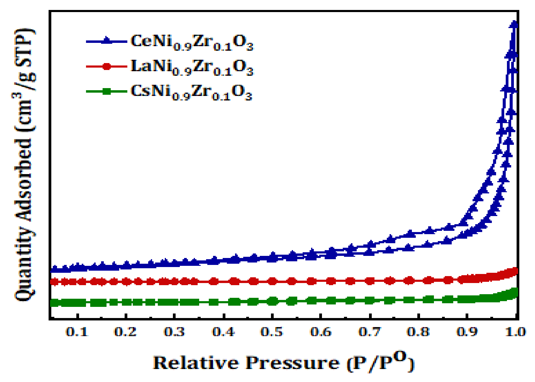
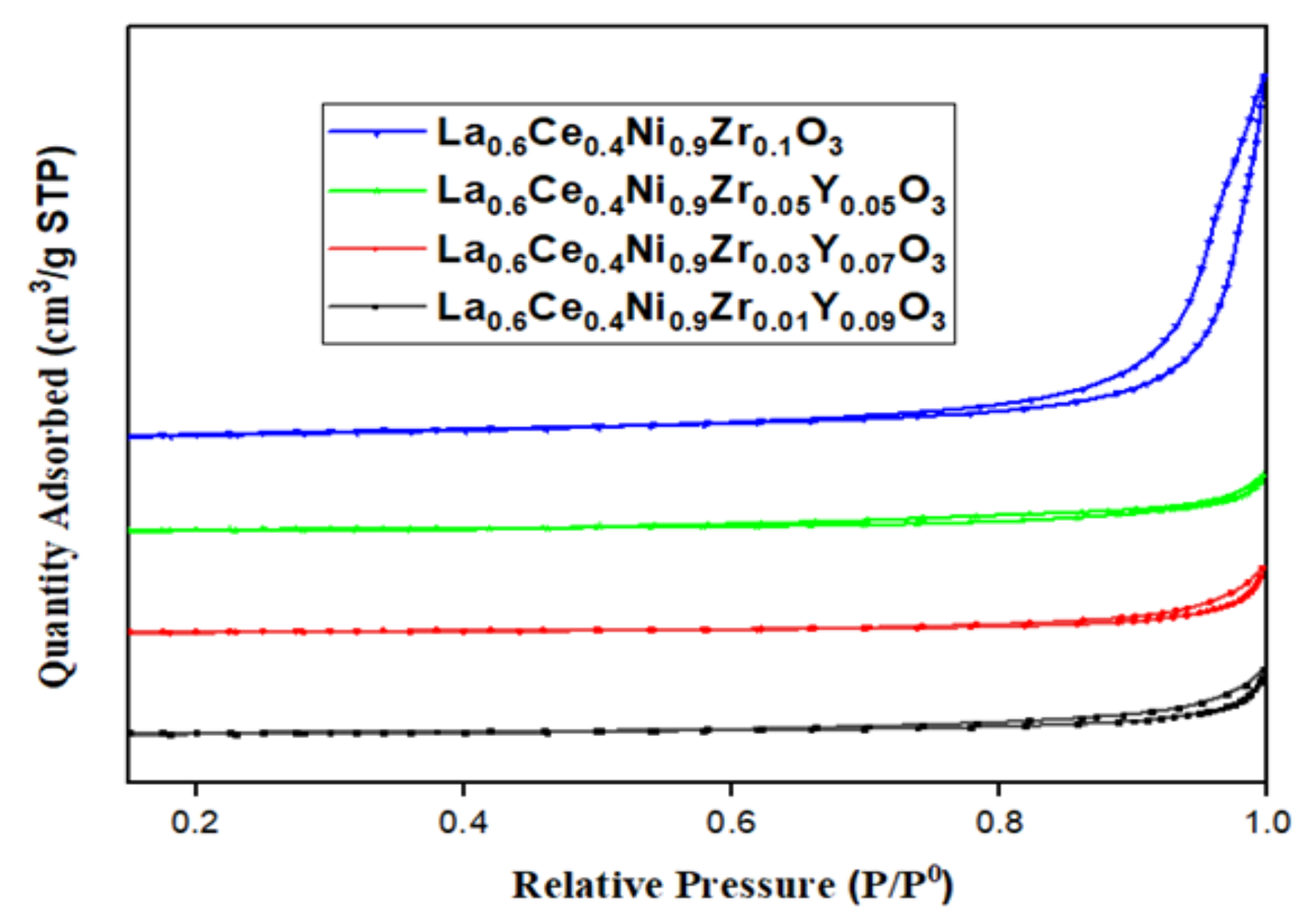
2.1. BET (Brunauer–Emmett–Teller) Analysis

The specific surface area of the catalysts based on the BET method range from 2 to 9 m2/g as shown in Table 1 and Table 2. The specific surface area of the samples is low due to the exposure of the precursor oxides to high temperatures; this is comparable with reported values in the literature [41]. From Table 2, the increase in the amount of yttrium does not significantly affect the surface area of the catalysts. Based on the IUPAC (International Union of Pure and Applied Chemistry) classification, the hysteresis loop of CeNi0.9 Zr0.1O3 is comparable to the H3 type, as shown in Figure 1. The isotherms of yttrium-containing samples shown in Figure 2 are similar in shape and comparable to type III. The surface area of CeNi0.9 Zr0.1O3 is slightly higher than La0.6Ce0.4Ni0.9 Zr0.1O3 and exhibits the highest surface area among the samples, with an isotherm comparable to type IV. The samples have particle sizes ranging from 12 to 35 nm. The isotherm curves shown in Figure 1 and Figure 2 suggest that the materials are mesoporous with a pore diameter greater than 2 nm but less than 50 nm [40].

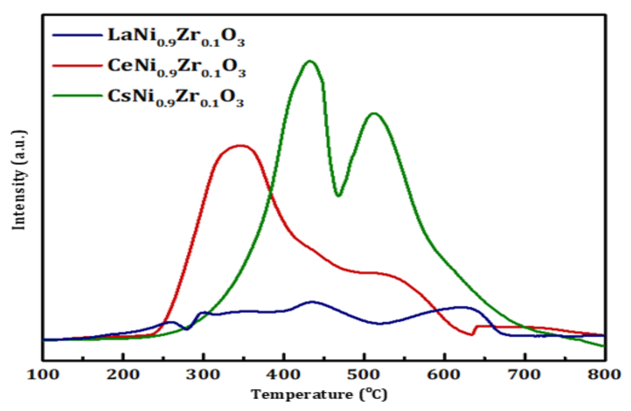
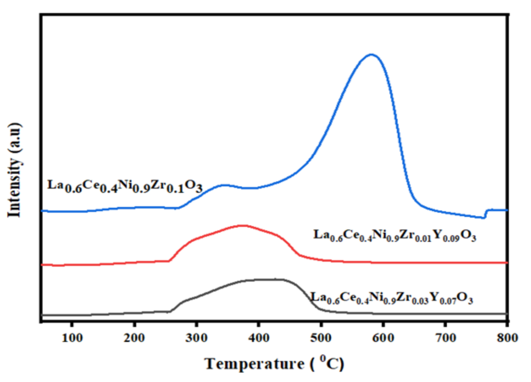
2.2. Temperature-Programmed Reduction (TPR)

The active sites for the catalyst MNi0.9Zr0.1O3 (M = La, Ce, and Cs) samples are Ni and Zr. The reducibility was determined as shown in Figure 3 and Figure 4. The reduction peaks are shown in the lower and moderate temperature regions. The TPR plot suggests that there was more than one element undergoing reduction. The peaks in the moderate temperature region can be attributed to the reduction of Ni3+ to Ni2+. Generally, the reduction becomes easier when the energy of the metal-oxygen bond decreases [41]. The cerium catalyst was reducible at lower temperatures than the lanthanum catalysts (Figure 3). The addition of yttria to lanthanum and cerium catalysts tends to move the reduction peak to the lower temperature region, with one reduction peak shown in Figure 4.

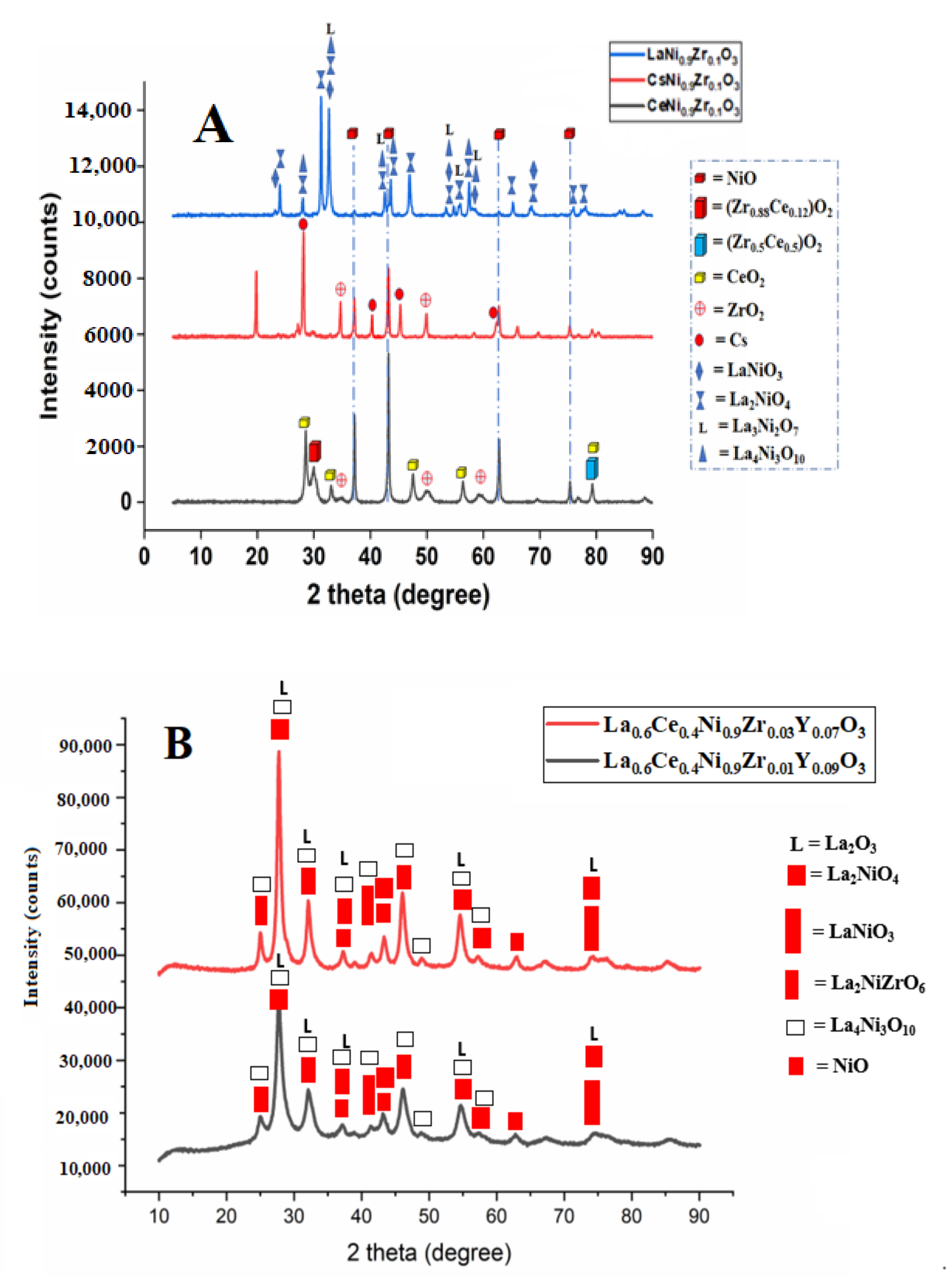
2.3. X-ray Diffraction (XRD) Analysis

The XRD peaks of the catalysts are depicted in Figure 5. The XRD peaks confirmed the formation of a monoclinic phase of zirconium at 2θ = 35.3° [41]. Peaks observed from the XRD include CeO2, NiO, and ZrO2 oxides. The rhombohedral phase of LaNiO3 (JCPDF 34-1028) is in agreement with peaks 2θ = 23.6°, 32.9°, 47.3°, and 60.0° [13]. For the CeNi0.9Zr0.1O3 catalyst, the intensity of the peaks at 2θ = 45.2° is higher, indicating that the substitution of La by Ce resulted in the formation of discrete crystalline phase of CeO2. The Ni in the Ce-Ni systems exists as NiO at the surface of the ceria and Ni2+ ions in the CeO2 lattice [13].

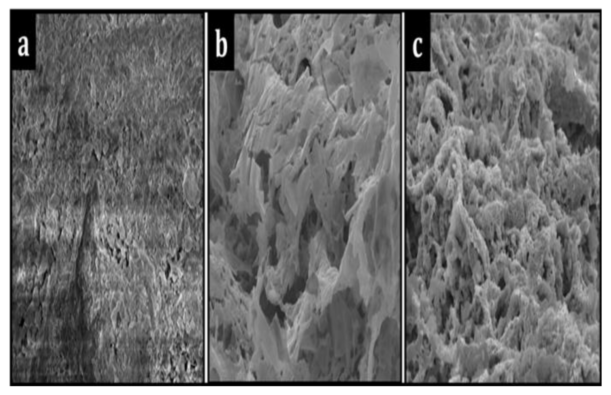
2.4. Scanning Electron Microscope (SEM) Analysis

Figure 6 shows the SEM images of fresh MNi0.9Zr0.1O3 (M = La, Ce, and Cs) catalysts. CeNi0.9Zr0.1O3 and LaNi0.9Zr0.1O3 catalysts appear to have irregularly shaped particles since both Ce and La belong to the same group in the periodic table. CsNi0.9Zr0.1O3 appears to have a less coarse surface.

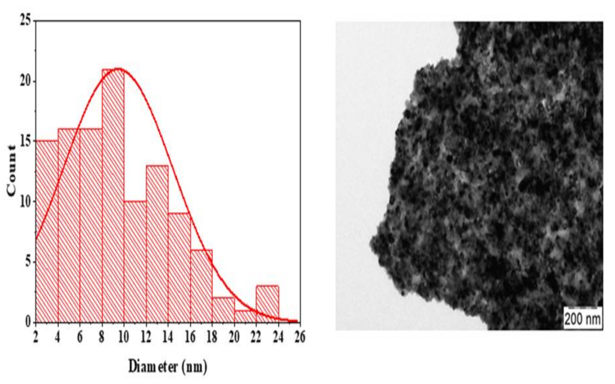
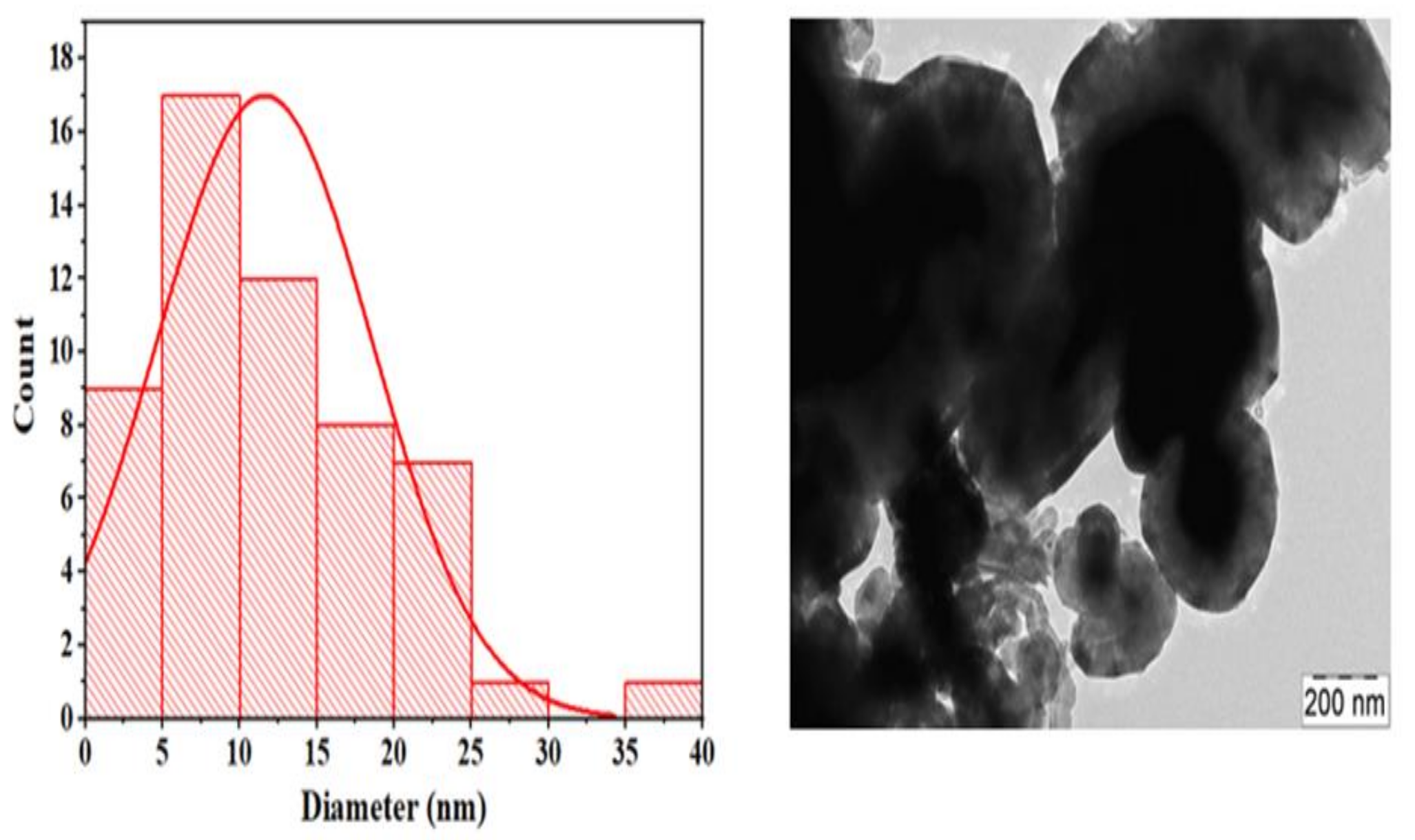
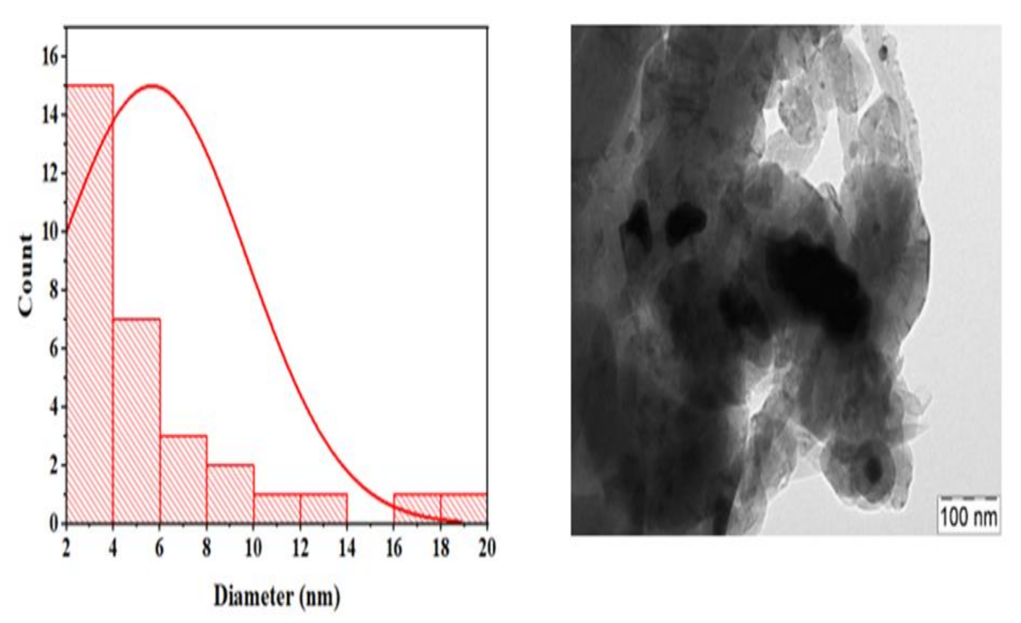
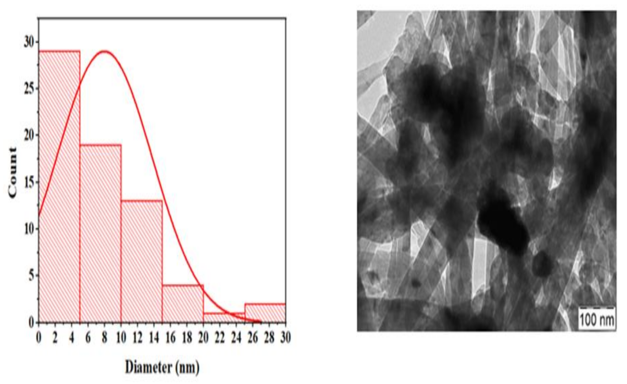
2.5. Transmission Electron Microscope (TEM) Analysis

The TEM analysis for both the fresh and spent catalysts are illustrated in Figure 7, Figure 8, Figure 9 and Figure 10 at 100 and 200 nm magnifications. For the used La0.6Ce0.4Ni0.9Zr0.01Y0.09O3 catalyst, the particles look dispersed with the carbon aggregating on a particular spot, while for the CeNi0.9Zr0.1O3 catalyst, clumsy particles are shown with the carbon spreading across the surface. The nickel particle size distribution expressed in nanometers is plotted for each of the TEM images, with that of the spent catalyst higher than the fresh catalyst samples. From Table 3, the La modification of catalysts significantly reduced the crystalline nickel size from 9.44 nm to 5.68 nm, which further proves the influence of uniform Ni distribution by La, which enhances the catalyst activity.

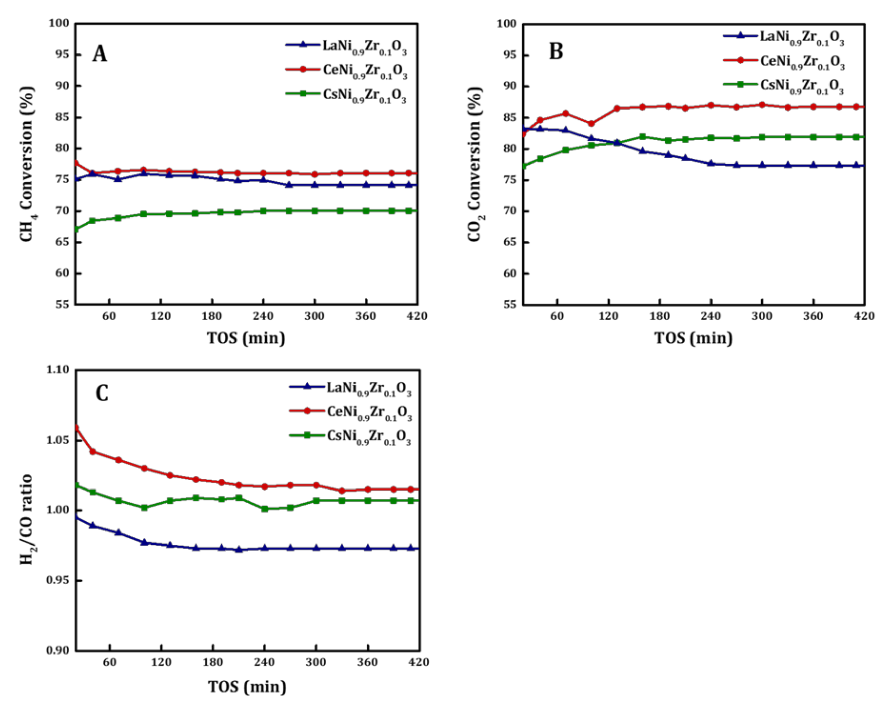
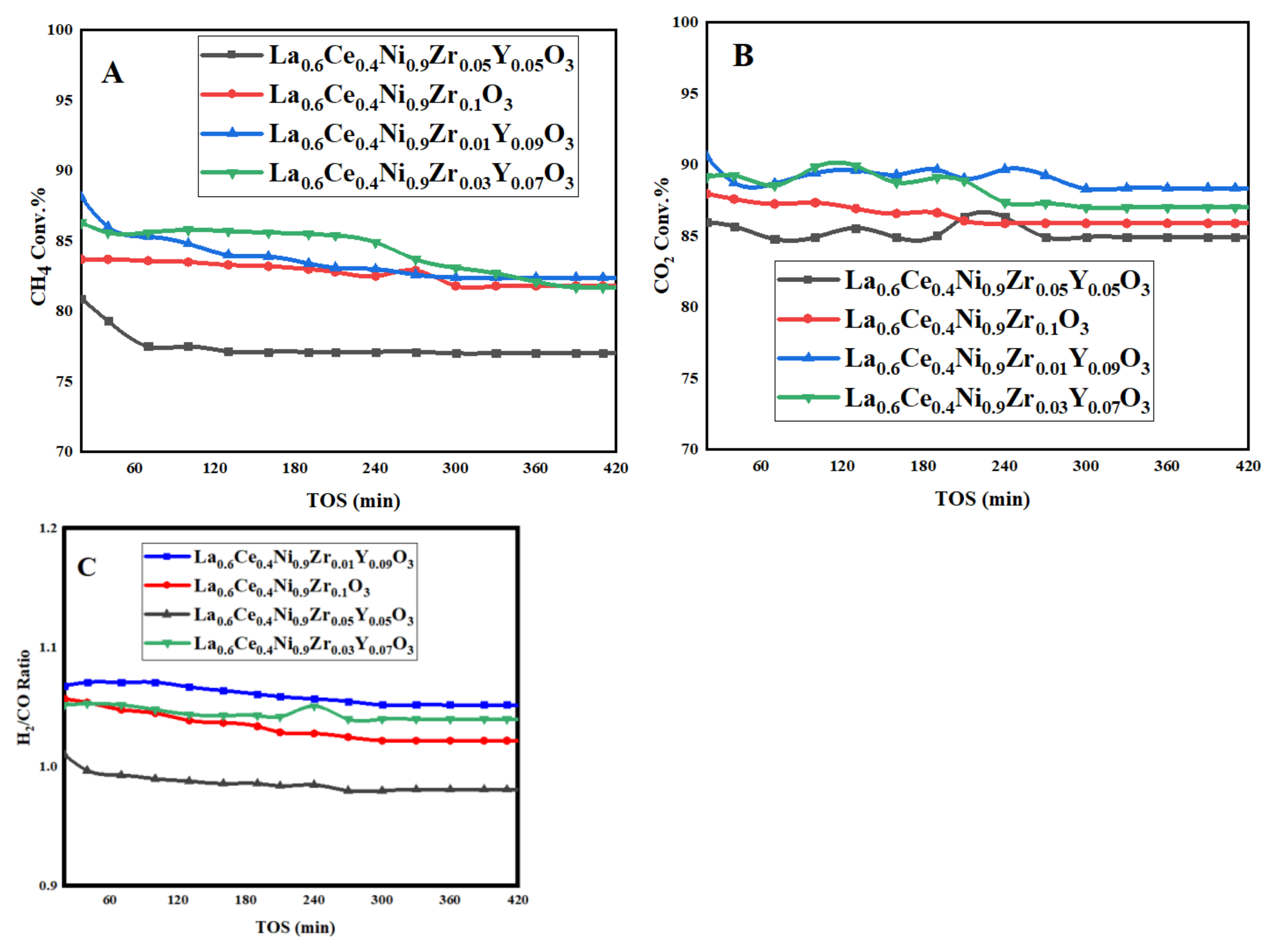
2.6. Catalyst Activity

The CH4 conversion was >75%, CO2 conversion >85%, and H2/CO >0.90, as shown in Figure 11 for the CeNi0.9Zr0.1O3 catalyst. The CsNi0.9Zr0.1O3 catalyst displayed CH4 conversion >70%, CO2 conversion >80%, and H2/CO >0.90, while the LaNi0.9Zr0.1O3 catalyst displayed CH4 conversion >65%, CO2 conversion >75%, and H2/CO >0.90 for the DRM reaction performed at 1073 K for 7 hours’ time on stream. CeO2 modifies the catalytic features of nickel-based catalysts in DRM based on its redox features and enables it to support CO2 activation (Ce2O3 + CO2 → 2CeO2 + CO) [42,43]. The value of the H2/CO ratio theoretically equals one but side reactions in the DRM experiment influence its actual value. The H2/CO ratio values for the tested catalyst are slightly greater than one; hence, the Boudouard reaction is predominant [18]. The CeNi0.9Zr0.1O3 catalyst shows better activity due to the abundance of oxygen vacancies, thereby creating more active sites. Studies have suggested that surface oxygen vacancy is responsible for the activation of methane. Cerium possesses a high enough capacity for oxygen storage and high mobility of lattice oxygen to improve catalytic behavior. An investigation of the influence of cerium on nickel-based catalysts for hydrogen production suggests that the addition of the right amount of cerium can increase oxygen vacancy formation, which can activate oxygen-containing compounds to react with a carbon species as soon as it forms. Lanthanum improved catalytic stability in the dry reforming of methane. The availability of La could lead to La2O2CO3; coke deposited on the interface between Ni and La2O2CO3 can be gasified via the reaction La2O2CO3 + C → La2O3 + 2CO. This reaction effectively suppresses coke formation on the catalyst.
A varying amount of Y was used to modify the catalyst La0.6Ce0.4Ni0.9Zr0.1O3 and the reaction was carried out at 1073 K to evaluate the effect of Y loading on the modified catalyst. The La0.6Ce0.4Ni0.9Zr0.1−xYxO3 (x = 0.05, 0.07, and 0.09) catalyst’s activity increases when the Y loading increases, as shown in Figure 12. The activity of La0.6Ce0.4Ni0.9Zr0.05Y0.05O3 is lower than the unmodified catalyst, hence the need to increase yttrium loading to 0.07 Y and 0.09 Y. The La0.6Ce0.4Ni0.9Zr0.1−xYxO3 catalyst’s activity increases with the increase in yttrium loading. The activities of the yttrium-modified catalysts La0.6Ce0.4Ni0.9Zr0.03Y0.07O3 and La0.6Ce0.4Ni0.9Zr0.01Y0.09O3 are higher than the unmodified La0.6Ce0.4Ni0.9Zr0.1O3 catalyst, with the latter having methane and carbon dioxide conversion values of 84% and 87%, respectively, and the former having methane and carbon dioxide conversion values of 86% and 90% for La0.6Ce0.4Ni0.9Zr0.03Y0.07O3 and 89% and 91% for La0.6Ce0.4Ni0.9Zr0.01Y0.09O3, respectively. Yttrium results in the formation of oxygen vacancies that are believed to contribute to improved catalytic activity. Y2O3 as a basic carrier allows Ni catalyst to be easily reduced and have better activity. Yttrium led to smaller Ni crystallites and enhanced the dispersion of active sites. Furthermore, doping ceria with yttrium was reported to enhance the number of oxygen vacancies and oxygen mobility. Ions of Ce3+ (0.97 Å) can be replaced by Y3+ (1.04 Å) and form a solid solution due to their similar ionic radii. La improves the interaction between the active component and the carrier, causing the even distribution of the Ni, which can be determined from SEM/EDX analysis [44]. Cerium possesses a high enough capacity of oxygen storage and high mobility of lattice oxygen to improve catalytic behavior [45]. CeO2 can create oxygen vacancies, which can eliminate carbon deposition by activating species of oxygen [35]. The ceria redox cycle between Ce3+ and Ce4+ helps to exude carbon deposited on the catalyst via oxygen vacancies [34]. Additionally, it was reported that CeO2 can increase catalytic activity via enhancing the dispersion of the surface-active component and the strong interaction between Ni and CeO2 inhibiting crystal growth [36,37]. Table 4 exhibits the results of this work compared to the literature. This table denotes the suitability of the synthesized catalysts in this process. The addition of yttria to the catalyst system enhances the activity performance as compared to previous work without yttria.

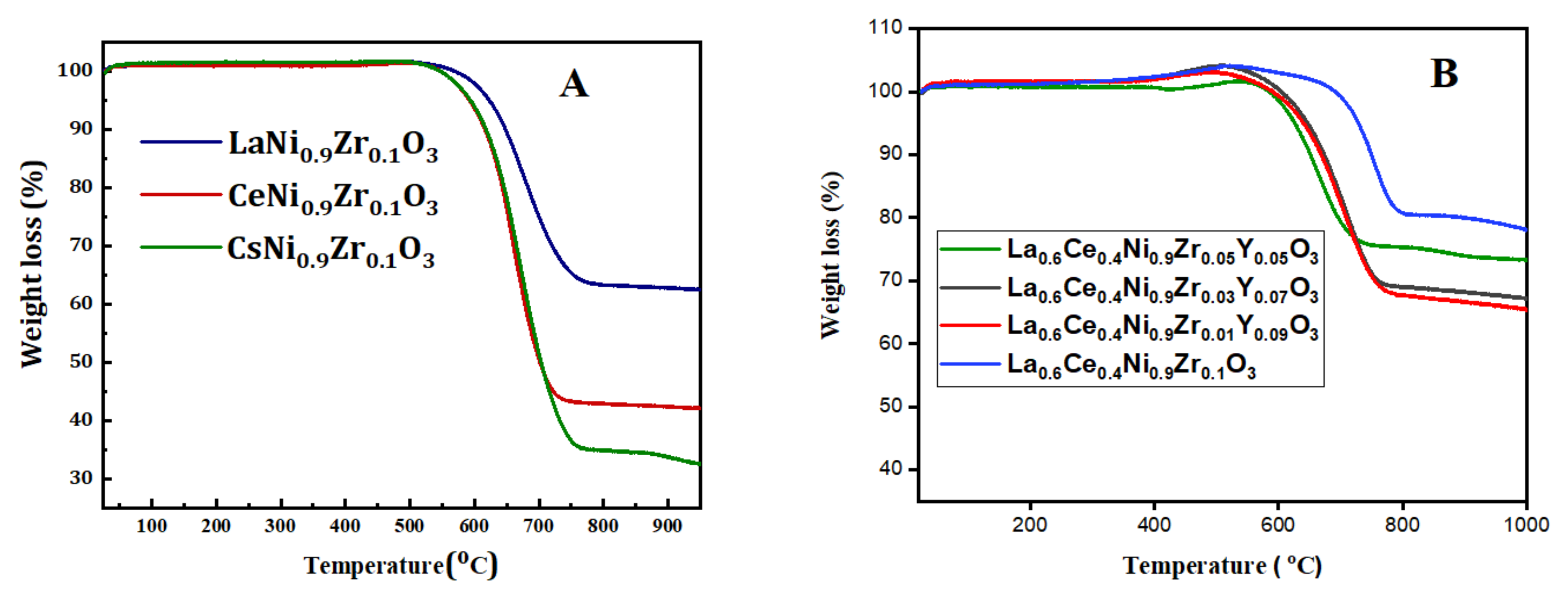
2.7. Thermogravimetric Analysis of the Used Catalyst (TGA)
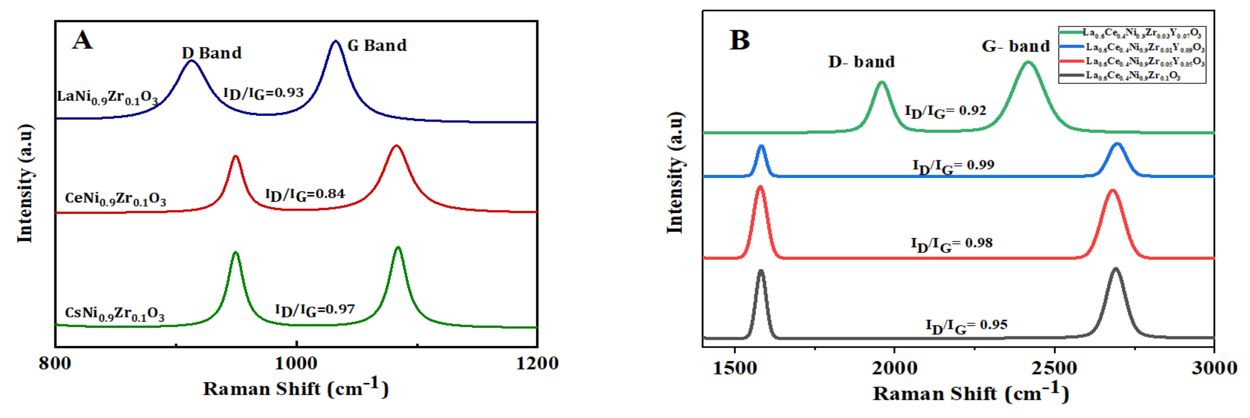
The amount of coke deposited on the catalysts was determined by TGA analysis after 7 h on stream, as depicted in Figure 13. The weight loss step is in the temperature range of 773 K–973 K, with the carbon deposition of CsNi0.9Zr0.1O3 being severe. The amount of carbon deposited on the La0.6Ce0.4Ni0.9Zr0.1O3 catalyst is the lowest, indicating that La improved carbon formation resistance [26]. Although, after adding La, carbon deposits exist in the form of filamentous carbon. Adding La does not only change the way carbon deposition occurs, but may also limit it to some extent [44].

2.8. RAMAN Analysis

Raman spectra of the used catalysts depict two bands with Raman shifts in the range of 950 ± 5 cm−1 and 1100 ± 10 cm−1, as shown in Figure 14A, and of 1574 ± 5 cm−1 and 2650 ± 10 cm−1, as shown in Figure 14B corresponding to D and G bands, respectively. The D band is related to coke deposits with imperfect or disordered structures (amorphous carbon), while the G band is a related to well-ordered structures (graphitic carbon). The value of the ID/IG ratio of the spent catalysts is relatively close. There is an increase in the Raman shift with the modified catalyst with yttrium.

3. Experimental Section

3.1. Catalyst Preparation

The catalysts were prepared by the sol–gel method with propionic acid acting as a solvent, to dissolve nitrates of each metal. In the preparation, La(NO3)3·6H2O (Sigma), Ni(NO3)2·6H2O (Sigma), Ce(NO3)3·6H2O (Sigma), Cs(NO3)3·6H2O (Sigma), Y(NO3)3·6H2O (Sigma) ZrO(NO3)2·6H2O (Sigma) and propionic acid (C3H6O2, Sigma) were used. The nitrates were separately dissolved in propionic acid, stirred, and heated at T = 363 K with oil as a heating medium in a closed vessel. Afterward, the solutions were mixed and stirred continuously for about 2 h at T = 403 K. Thereafter, the propionic acid was evaporated using a rotary evaporator at T = 343 K until a gel was formed. The gel obtained was dried at T = 363 K overnight, and calcined at 998 K for 4 h. The calcined catalysts were ground into powder and used for the DRM reaction.

3.2. Catalytic Testing

The catalysts were tested for DRM at 1073 K reaction temperature under atmospheric pressure. A packed bed stainless-steel reactor (internal diameter, 0.0091 m; height, 0.3 m) was used to perform the experiments. A catalyst mass of 0.10 g was positioned in the reactor over a ball of glass wool. Stainless steel, sheathed thermocouple K-type, axially positioned close to the catalyst bed was used to determine the temperature during the reaction. Preceding the reaction, activation of the perovskite catalysts was achieved at 973 K in an atmosphere of H2. This lasted for 60 min and the remnant H2 was purged with N2. During the dry reforming reaction, the feed volume ratio was kept at 3:3:1 for CH4, CO2, and N2 gases, respectively, with a space velocity of 42 L/h·gcat. The outlet gas from the reactor was connected to an online Gas Chromatograph (GC) with a thermal conductivity detector to analyze its composition. The CH4, CO2 conversion, and H2/CO (syngas ratio) were calculated using Equations (4)–(6):
Methane   conversion   % = CH 4 , in CH 4 , out CH 4 , in 100
Carbon   dioxide   conversion   % = CO 2 , in CO 2 , out CO 2 , in 100
Syngas   Ratio = mole   of   H 2   produced mole   of   CO   produced

3.3. Determination of Catalyst’s Physicochemical Properties

3.3.1. Nitrogen Physisorption

The catalyst’s surface area and the pore size distribution were measured by N2 adsorption–desorption at 77 K using a Micromeritics Tristar II 3020 for porosity and surface area analyzer.

3.3.2. Temperature Programmed Reduction (TPR) Analysis

An amount of 70 mg of the sample was loaded inside the TPR sample holder of a Micromeritics apparatus. Thereafter, TPR measurements were performed at 423 K using Ar gas for 30 min. Afterward, the sample was cooled to ambient temperature. The next step involved heating by the furnace up to 1073 K ramping at 283 K min−1, in an atmosphere of H2/Ar mixture (1:9 vol. %) flowing at 40 mL/min. The thermal conductivity unit recorded the consumption of H2 during the operation.

3.3.3. Thermo-Gravimetric Analysis (TGA)

The quantity of carbon deposited on the spent catalysts was measured by the TG analysis. Here, a platinum pan was filled with 10–15 mg of the used catalysts. Heating was carried out from room temperature up to 1273 K at 293 K min−1 temperature ramp. Change in mass was constantly monitored as the heating progressed.

3.3.4. X-ray Diffraction (XRD) Analysis

The X-ray Diffraction patterns of the perovskite catalysts were recorded on a Miniflex Rigaku diffractometer that was equipped with Cu Kα X-ray radiation. The device was run at 40 kV and 40 mA.

3.3.5. Transmission Electron Microscopy (TEM)

Transmission electron microscopy (JEOL JEM-2100F) with high resolution to give larger magnification was used to carry out the TEM measurement of both the fresh and used catalysts. The electron microscope operated at 200 kV produces the active metal nickel particle sizes and depicts the morphology of carbon deposited on the used catalyst. Before the TEM measurement, the catalysts were first dispersed ultrasonically in ethanol at room temperature. Thereafter, the drop from the suspension was placed in a lacey carbon-coated copper grid to produce the images.

3.3.6. Laser Raman (NMR-4500) Spectrometer

Laser Raman (NMR-4500) Spectrometer (JASCO, Japan) was used to record Raman spectra of the spent catalyst samples. The wavelength of the excitation beam was set to 532 nm, and an objective lens of 100× magnification was used for the measurement. The laser intensity was adjusted to 1.6 mW. Each spectrum was received by averaging 3 exposures on 10 s. Spectra were recorded in the range 1200–3000 cm−1 (Raman shift) and were processed by using Spectra Manager Ver.2 software (JASCO, Tokyo, Japan).

4. Conclusions

The activity of the LaNi0.9Zr0.1O3 catalyst was significantly improved by partial substitution with cerium, which enhances catalyst activity due to the abundance of oxygen vacancies. The methane conversion activity of the best-modified catalyst (La0.6Ce0.4Ni0.9Zr0.01Y0.09O3) is significantly higher than the base catalyst (LaNi0.9Zr0.1O3). La0.6Ce0.4Ni0.9Zr0.1O3 activity is higher than the modified catalyst at 0.05 Y, but lower than 0.07 Y and 0.09 Y, which suggests that the activity of the modified catalyst increases above 0.05 Y. The catalyst activity increases with an increase in yttrium loading, with the La0.6Ce0.4Ni0.9Zr0.01Y0.09O3 catalyst having the best activity with a CH4 conversion >89% and CO2 conversion >91%. The Raman analysis suggests that carbon deposits on the catalysts are graphitic carbon. La0.6Ce0.4Ni0.9Zr0.1O3 has the least carbon, indicating that La improved the carbon formation resistance since thermal resistance is controlled by A-cations. Furthermore, the amount of carbon deposited on the catalyst decreases with the increase in zirconium amount; hence, zirconium also enhances catalyst stability. Supplementary characterization has been explained in the Supplementary Materials.

Supplementary Materials

The following are available online at https://0-www-mdpi-com.brum.beds.ac.uk/article/10.3390/catal12070715/s1, Figure S1. The EDX analysis of fresh catalysts (A) CsNi0.9Zr0.1O3 (B) CeNi0.9Zr0.1O3 (C) LaNi0.9Zr0.1O3; Figure S2. CO2-TPD profiles of fresh catalysts: La0.6Ce0.4Ni0.9Zr0.01Y0.09O3 and La0.6Ce0.4Ni0.9Zr0.1O3; Figure S3. TPO profile of used catalysts: La0.6Ce0.4Ni0.9Zr0.01Y0.09O3.

Author Contributions

Experiment, M.S.L.; writing—original draft, M.S.L. and A.S.A.-F.; preparation of the catalyst, M.S.L. and A.S.A.-F.; characterization of catalyst, M.S.L., A.S.A.-A., A.b.J. and A.A.I.; writing—review and editing, A.H.F., A.E.A., F.S.A.-M. and A.A.I. All authors have read and agreed to the published version of the manuscript.

Funding

The authors would like to sincerely thank Researchers Supporting Project number (RSP-2021/368), King Saud University, Riyadh, Saudi Arabia.

Acknowledgments

The authors would like to extend their sincere appreciation to the Researchers Supporting Project number (RSP-2021/368), King Saud University, Riyadh, Saudi Arabia.

Conflicts of Interest

The authors declare no conflict of interest.

References

  1. Valderrama, G.; Kiennemann, A.; Goldwasser, M.R. La-Sr-Ni-Co-O based perovskite-type solid solutions as catalyst precursors in the CO2 reforming of methane. J. Power Sources 2010, 195, 1765. [Google Scholar] [CrossRef]
  2. Gallego, G.S.; Marín, J.G.; Batiot-Dupeyrat, C.; Barrault, J.; Mondragón, F. Influence of Pr and Ce in dry methane reforming catalysts produced from La1−xAxNiO3−δ perovskites. Appl. Catal. A Gen. 2009, 369, 97. [Google Scholar] [CrossRef]
  3. Steinhauer, B.; Kasireddy, M.R.; Radnik, J.; Martin, A. Development of Ni-Pd bimetallic catalysts for the utilization of carbon dioxide and methane by dry reforming. Appl. Catal. A Gen. 2009, 366, 333. [Google Scholar] [CrossRef]
  4. Liu, H.; Wierzbicki, D.; Debek, R.; Motak, M.; Grzybek, T.; Da Costa, P.; Gálvez, M.E. La-promoted Ni-hydrotalcite-derived catalysts for dry reforming of methane at low temperatures. Fuel 2016, 182, 8. [Google Scholar] [CrossRef]
  5. San-José-Alonso, D.; Juan-Juan, J.; Illán-Gómez, M.J.; Román-Martínez, M.C. Ni, Co and bimetallic Ni-Co catalysts for the dry reforming of methane. Appl. Catal. A Gen. 2009, 371, 54. [Google Scholar] [CrossRef]
  6. Hanley, E.S.; Deane, J.P.; Gallachóir, B.P.Ó. The role of hydrogen in low carbon energy futures–A review of existing perspectives Renew. Sustain. Energy Rev. 2018, 82, 3027. [Google Scholar] [CrossRef]
  7. Al-mubaddel, F.S.; Kumar, R.; Lanre, M.; Frusteri, F.; Aidid, A.; Kumar, V.; Olajide, S.; Hamza, A.; Elhag, A.; Osman, A.I.; et al. Optimizing acido-basic profile of support in Ni supported La2O3 + Al2O3 catalyst for dry reforming of methane. Int. J. Hydrogen Energy 2021, 46, 14225–14235. [Google Scholar] [CrossRef]
  8. Rahmani, F.; Haghighi, M.; Vafaeian, Y.; Estifaee, P. Hydrogen production via CO2 reforming of methane over ZrO2-Doped Ni/ZSM-5 nanostructured catalyst prepared by ultrasound assisted sequential impregnation method. J. Power Sources 2014, 272, 816. [Google Scholar] [CrossRef]
  9. Zhang, L.; Wang, X.; Chen, C.; Zou, X.; Ding, W.; Lu, X. Dry reforming of methane to syngas over lanthanum-modified mesoporous nickel aluminate/γ-alumina nanocomposites by one-pot synthesis. Int. J. Hydrogen Energy 2017, 42, 11333. [Google Scholar] [CrossRef]
  10. Al-Fatish, A.S.A.; Ibrahim, A.A.; Fakeeha, A.H.; Soliman, M.A.; Siddiqui, M.R.H.; Abasaeed, A.E. Coke formation during CO2 reforming of CH4 over alumina-supported nickel catalysts. Appl. Catal. A Gen. 2009, 364, 150. [Google Scholar] [CrossRef]
  11. Itkulova, S.S.; Nurmakanov, Y.Y.; Kussanova, S.K.; Boleubayev, Y.A. Production of a hydrogen-enriched syngas by combined CO2-steam reforming of methane over Co-based catalysts supported on alumina modified with zirconia. Catal. Today 2018, 299, 272. [Google Scholar] [CrossRef]
  12. Sutthiumporn, K.; Maneerung, T.; Kathiraser, Y.; Kawi, S. CO2 dry-reforming of methane over La0.8Sr0.2Ni0.8M0.2O3 perovskite (M = Bi, Co, Cr, Cu, Fe): Roles of lattice oxygen on C–H activation and carbon suppression. Int. J. Hydrogen Energy 2012, 37, 11195. [Google Scholar] [CrossRef]
  13. Sim, Y.; Kwon, D.; An, S.; Ha, J.M.; Oh, T.S.; Jung, J.C. Catalytic behavior of ABO3 perovskites in the oxidative coupling of methane. Mol. Catal. 2020, 489, 110925. [Google Scholar] [CrossRef]
  14. Kathiraser, Y.; Oemar, U.; Saw, E.T.; Li, Z.; Kawi, S. Kinetic and mechanistic aspects for CO2 reforming of methane over Ni based catalysts. Chem. Eng. J. 2015, 278, 62. [Google Scholar] [CrossRef]
  15. Fakeeha, A.H.; Bagabas, A.A.; Lanre, M.S.; Osman, A.I.; Elnour, A.Y.; Abasaeed, A.E.; Al-fatesh, A.S. Catalytic Performance of Metal Oxides Promoted Nickel Catalysts Supported on Mesoporous γ-Alumina in Dry Reforming of Methane. Process 2020, 8, 522. [Google Scholar] [CrossRef]
  16. Xu, L.; Song, H.; Chou, L. Carbon dioxide reforming of methane over ordered mesoporous NiO-MgO-Al2O3 composite oxides. Appl. Catal. B Environ. 2011, 177, 108. [Google Scholar] [CrossRef]
  17. Lanre, M.S.; Al-Fatesh, A.S.; Fakeeha, A.H.; Kasim, S.O.; Ibrahim, A.A.; Al-Awadi, A.S.; Al-Zahrani, A.A.; Abasaeed, A.E.; Sa, A.S.A. Catalytic Performance of Lanthanum Promoted Ni/ZrO2 for Carbon Dioxide Reforming of Methane. Process 2020, 8, 1502. [Google Scholar] [CrossRef]
  18. Fang, X.; Peng, C.; Peng, H.; Iu, W.; Xu, X.; Wang, X.; Li, C.; Hou, W. Methane Dry Reforming over Coke-Resistant Mesoporous Ni-Al2O3 Catalysts Prepared by Evaporation-Induced Self-Assembly Method. ChemCatChem 2015, 7, 3753. [Google Scholar] [CrossRef]
  19. Patel, R.; Fakeeha, A.H.; Kasim, S.O.; Sofiu, M.L.; Ibrahim, A.A.; Abasaeed, A.E.; Kumar, R.; Al-Fatesh, A.S. Optimizing yttria-zirconia proportions in Ni supported catalyst system for H2 production through dry reforming of methane. Mol. Catal. 2021, 510, 111676. [Google Scholar] [CrossRef]
  20. Ewbank, J.L.; Kovarik, L.; Diallo, F.Z.; Sievers, C. Effect of metal-support interactions in Ni/Al2O3 catalysts with low metal loading for methane dry reforming. Appl. Catal. A Gen. 2015, 494, 57. [Google Scholar] [CrossRef] [Green Version]
  21. Oemar, U.; Li Ang, M.; Hidajat, K.; Kawi, S. Enhancing performance of Ni/La2O3 catalyst by Sr-modification for steam reforming of toluene as model compound of biomass tar. RSC Adv. 2015, 5, 17834. [Google Scholar] [CrossRef]
  22. Zou, X.; Wang, X.; Li, L.; Shen, K.; Lu, X.; Ding, W. Development of highly effective supported nickel catalysts for pre-reforming of liquefied petroleum gas under low steam to carbon molar ratios. Int. J. Hydrogen Energy 2010, 35, 12191. [Google Scholar] [CrossRef]
  23. Shen, K.; Wang, X.; Zou, X.; Wang, X.; Lu, X.; Ding, W. Pre-reforming of liquefied petroleum gas over nickel catalysts supported on magnesium aluminum mixed oxides. Int. J. Hydrogen Energy 2011, 36, 4908. [Google Scholar] [CrossRef]
  24. Råberg, L.B.; Jensen, M.B.; Olsbye, U.; Daniel, C.; Haag, S.; Mirodatos, C.; Sjåstad, A.O. Propane dry reforming to synthesis gas over Ni-based catalysts: Influence of support and operating parameters on catalyst activity and stability. J. Catal. 2007, 249, 250. [Google Scholar] [CrossRef]
  25. Liu, D.; Quek, X.Y.; Cheo, W.N.E.; Lau, R.; Borgna, A.; Yang, Y. MCM-41 supported nickel-based bimetallic catalysts with superior stability during carbon dioxide reforming of methane: Effect of strong metal-support interaction. J. Catal. 2009, 266, 380. [Google Scholar] [CrossRef]
  26. Batiot-Dupeyrat, C.; Valderrama, G.; Meneses, A.; Martinez, F.; Barrault, J.; Tatibouët, J.M. Pulse study of CO2 reforming of methane over LaNiO3. Appl. Catal. A Gen. 2003, 248, 143. [Google Scholar] [CrossRef]
  27. Liu, Q.; Gu, F.; Lu, X.; Liu, Y.; Li, H.; Zhong, Z.; Xu, G.; Su, F. Enhanced catalytic performances of Ni/Al2O3 catalyst via addition of V2O3 for CO methanation. Appl. Catal. A Gen. 2014, 488, 37. [Google Scholar] [CrossRef]
  28. Valderrama, G.; Urbina De Navarro, C.; Goldwasser, M.R. CO2 reforming of CH4 over Co–La-based perovskite-type catalyst precursors. J. Power Sources 2013, 234, 31. [Google Scholar] [CrossRef]
  29. Ginsburg, J.M.; Piña, J.; Solh, T.; de Lasa, H.I. Coke Formation over a Nickel Catalyst under Methane Dry Reforming Conditions: Thermodynamic and Kinetic Models. Ind. Eng. Chem. Res. 2005, 44, 4846. [Google Scholar] [CrossRef]
  30. Zhang, X.; Zhang, Q.; Tsubaki, N.; Tan, Y.; Han, Y. Influence of zirconia phase on the performance of Ni/ZrO2. Appl. Catal. A 2015, 34, 135. [Google Scholar] [CrossRef]
  31. Kopyscinski, J.; Schildhauer, T.J.; Biollaz, S.M.A. Production of synthetic natural gas (SNG) from coal and dry biomass—A technology review from 1950 to 2009. Fuel 2010, 89, 1763. [Google Scholar] [CrossRef]
  32. Choi, S.O.; Moon, S.H. Performance of La1−xCexFe0.7Ni0.3O3 perovskite catalysts for methane steam reforming. Catal. Today 2009, 146, 148. [Google Scholar] [CrossRef]
  33. Luo, J.Z.; Yu, Z.L.; Ng, C.F.; Au, C.T. CO2/CH4 Reforming over Ni–La2O3/5A: An Investigation on Carbon Deposition and reaction steps. J. Catal. 2000, 194, 198. [Google Scholar] [CrossRef]
  34. Liu, F.; Zhao, L.; Wang, H.; Bai, X.; Liu, Y. Study on the preparation of Ni–La–Ce-oxide catalyst for steam reforming of ethanol. Int. J. Hydrogen Energy 2014, 39, 10454. [Google Scholar] [CrossRef]
  35. Yang, E.H.; Kim, N.Y.; Noh, Y.-S.; Lim, S.S.; Jung, J.-S.; Lee, J.S.; Hong, G.H.; Moon, D.J. Steam CO2 reforming of methane over La1−xCexNiO3 perovskite catalysts. Int. J. Hydrogen Energy 2015, 40, 11831. [Google Scholar] [CrossRef]
  36. Lima, S.M.; Assaf, J.M.; Peña, M.A.; Fierro, J.L.G. Structural features of La1−xCexNiO3 mixed oxides and performance for the dry reforming of methane. Appl. Catal. A Gen. 2006, 311, 94. [Google Scholar] [CrossRef]
  37. Wang, Y.Z.; Li, F.M.; Cheng, H.M.; Fan, L.Y.; Zhao, Y.X. A comparative study on the catalytic properties of high Ni-loading Ni/SiO2 and low Ni-loading Ni-Ce/SiO2 for CO methanation. J. Fuel Chem. Technol. 2013, 41, 972. [Google Scholar] [CrossRef]
  38. Frontera, P.; Candamano, M.A.; Crea, S.; Barberio, F.M.; Antonucci, P.L. Alkaline-Promoted Zeolites for Methane Dry-Reforming Catalyst Preparation. Adv. Sci. Lett. 2017, 23, 5883. [Google Scholar] [CrossRef]
  39. Therdthianwong, S.; Therdthianwong, A.; Siangchin, C.; Yongprapat, S. Synthesis gas production from dry reforming of methane over Ni/Al2O3 stabilized by ZrO2. Int. J. Hydrogen Energy 2008, 33, 991. [Google Scholar] [CrossRef]
  40. Choque, V.; De la Piscina, P.R.; Molyneux, D.; Homs, N. Ruthenium supported on new TiO2-ZrO2 systems as catalysts for the partial oxidation of methane. Catal. Today 2010, 149, 248. [Google Scholar] [CrossRef]
  41. Talaie, N.; Sadr, M.H.; Aghabozorg, H.; Zare, K. Synthesis and application of LaNiO3 perovskite-type nanocatalyst with Zr for carbon dioxide reforming of methane. Orient. J. Chem. 2016, 32, 2723. [Google Scholar] [CrossRef] [Green Version]
  42. Dama, S.; Ghodke, S.R.; Bobade, R.; Gurav, H.R.; Chilukuri, S. Active and durable alkaline earth metal substituted perovskite catalysts for dry reforming of methane. Appl. Catal. B Environ. 2018, 224, 146. [Google Scholar] [CrossRef]
  43. Lanre, M.S.; Abasaeed, A.E.; Fakeeha, A.H.; Ibrahim, A.A.; Alquraini, A.A.; AlReshaidan, S.B.; Al-Fatesh, A.S. Modification of CeNi0.9Zr0.1O3 Perovskite Catalyst by Partially Substituting Yttrium with Zirconia in Dry Reforming of Methane. Materials 2022, 15, 3564. [Google Scholar] [CrossRef]
  44. Li, J.; Gao, R.; Zhu, L.; Zhang, Y.; Li, Z.; Li, B.; Wang, J.; He, J.; He, Y.; Qin, Z.; et al. Hydrogen-Rich Gas Production with the Ni-La/Al2O3-CaO-C Catalyst from Co-Pyrolysis of Straw and Polyethylene. Catalysts 2022, 12, 496. [Google Scholar] [CrossRef]
  45. Dezvareha, P.; Aghabozorgb, H.; Hossaini Sadrc, M.; Zared, K. Synthesis, characterization, and catalytic performance of La1−xCexNi1−yZryO3 perovskite nanocatalysts in dry reforming of methane. Orient. J. Chem. 2018, 34, 1469–1477. [Google Scholar] [CrossRef] [Green Version]
Figure 1. Nitrogen physisorption isotherms of catalyst MNi0.9Zr0.1O3 (M = La, Ce, and Cs).
Catalysts 12 00715 g001
Figure 2. Nitrogen physisoption isotherms of catalyst La0.6Ce0.4Ni0.9Zr0.1−xYxO3 (x = 0.05, 0.07, and 0.09).
Catalysts 12 00715 g002
Figure 3. H2-TPR profiles of catalyst MNi0.9Zr0.1O3 (M = La, Ce, and Cs).
Catalysts 12 00715 g003
Figure 4. H2-TPR profiles of catalyst La0.6Ce0.4Ni0.9Zr0.1−xYxO3 (x = 0.05, 0.07, and 0.09).
Catalysts 12 00715 g004
Figure 5. XRD patterns of catalyst: (A) MNi0.9Zr0.1O3 (M = La, Ce, and Cs); (B) La0.6Ce0.4Ni0.9Zr0.1−xYxO3 (x = 0.07 and 0.09).
Catalysts 12 00715 g005
Figure 6. SEM image of fresh catalysts: (a) CsNi0.9Zr0.1O3; (b) CeNi0.9Zr0.1O3; (c) LaNi0.9Zr0.1O3.
Catalysts 12 00715 g006
Figure 7. TEM of fresh CeNi0.9Zr0.1O3.
Catalysts 12 00715 g007
Figure 8. TEM of used CeNi0.9Zr0.1O3.
Catalysts 12 00715 g008
Figure 9. TEM of fresh La0.6Ce0.4Ni0.9Zr0.01Y0.09O3.
Catalysts 12 00715 g009
Figure 10. TEM of used La0.6Ce0.4Ni0.9Zr0.01Y0.09.
Catalysts 12 00715 g010
Figure 11. (A) CH4 conversion; (B) CO2 conversion; (C) H2/CO ratio of catalyst MNi0.9Zr0.1O3 (M = La, Ce and Cs) at 1073 K, 1 Atmosphere and GHSV = 42 L/(h·gcat.).
Catalysts 12 00715 g011
Figure 12. (A) CH4 conversion; (B) CO2 conversion; (C) H2/CO ratio of catalyst La0.6Ce0.4Ni0.9Zr0.1−xYxO3 (x = 0.05, 0.07, and 0.09) at 1073 K, 1 Atmosphere and GHSV = 42 L/(h·gcat.).
Catalysts 12 00715 g012
Figure 13. TGA curves of catalysts: (A) MNi0.9Zr0.1O3 (M = La, Ce and Cs) at 1073 K; (B) La0.6Ce0.4Ni0.9Zr0.1−xYxO3 (x = 0.05, 0.07 and 0.09).
Catalysts 12 00715 g013
Figure 14. Raman spectra of used catalyst: (A) MNi0.9Zr0.1O3 (M = La, Ce and Cs); (B) La0.6Ce0.4Ni0.9Zr0.1−xYxO3 (x = 0.05, 0.07, and 0.09).
Catalysts 12 00715 g014
Table 1. Specific surface area (SSA), Pore volume (Pv), and Pore diameter (Pd) of the fresh catalyst samples.
SamplesSSA, m2/gPv, cm3/gPd, nm
CsNi0.9 Zr0.1O35.190.02925.33
LaNi0.9 Zr0.1O35.330.02725.82
CeNi0.9 Zr0.1O39.350.03112.12
Table 2. Specific surface area (SSA), Pore volume (Pv) and Pore diameter (Pd) of the fresh catalyst samples.
SamplesSSA (m2/g)Pv (cm3/g)Pd (nm)
La0.6Ce0.4Ni0.9Zr0.1O38.360.06535.32
La0.6Ce0.4Ni0.9Zr0.05Y0.05O33.240.0116.02
La0.6Ce0.4Ni0.9Zr0.03Y0.07O32.470.01126.62
La0.6Ce0.4Ni0.9Zr0.01Y0.09O32.640.01122.43
Table 3. Nickel particle size derived from TEM analysis.
Catalyst NamesNi Particle Size
Fresh CeNi0.9Zr0.1O39.44 nm
Used CeNi0.9Zr0.1O311.68 nm
Fresh La0.6Ce0.4Ni0.9Zr0.01Y0.09O35.68 nm
Used La0.6Ce0.4Ni0.9Zr0.01Y0.09O38.05 nm
Table 4. Comparison of the results of this work with those of the literature.
Catalyst ConstituentsOperating TemperatureProduct/ConversionRef.
La0.95Ce0.05NiO31023 KCH4 = 50
CO2 = 60
[36]
La0.6Ce0.4NiO31023 KCH4 = 47
CO2 = 58
[36]
La0.3Ce0.7NiO31023 KCH4 = 30
CO2 = 36
[36]
La0.9Ce0.1Ni0.9Zr0.1O31073 KCH4 = 40
CO2 = 60
[45]
La0.9Ce0.1Ni0.8Zr0.2O31073 KCH4 = 60
CO2 = 80
[45]
La0.9Ce0.1Ni0.7Zr0.3O31073 KCH4 = 10
CO2 = 20
[45]
La0.6Ce0.4Ni0.9Zr0.1O31073 KCH4 = 84
CO2 = 87
[this work]
La0.6Ce0.4Ni0.9Zr0.05Y0.05O31073 KCH4 = 80
CO2 =85
[this work]
La0.6Ce0.4Ni0.9Zr0.03Y0.07O31073 KCH4 = 86
CO2 = 90
[this work]
La0.6Ce0.4Ni0.9Zr0.01Y0.09O31073 KCH4 = 89
CO2 = 91
[this work]
Publisher’s Note: MDPI stays neutral with regard to jurisdictional claims in published maps and institutional affiliations.

