
Carbon-Protected BiVO4—Cu2O Thin Film Tandem Cell for Solar Water Splitting Applications

1
Centre for Nanotechnology Research, Vellore Institute of Technology, Vellore 632014, India
2
School of Electronics Engineering, Vellore Institute of Technology, Vellore 632014, India
*
Author to whom correspondence should be addressed.
Catalysts 2023, 13(1), 144; https://0-doi-org.brum.beds.ac.uk/10.3390/catal13010144
Submission received: 30 November 2022
/
Revised: 1 January 2023
/
Accepted: 3 January 2023
/
Published: 7 January 2023
(This article belongs to the Special Issue Advances in Photocatalytic Processes for Sustainable Energy Conversion and Environmental Engineering)
Abstract
:Carbon-protected BiVO4 photoanode and Cu2O photocathode tandem photoelectrochemical (PEC) system has been explored to reduce surface recombination and enhance the stability of the photoelectrodes. In addition to the carbon layer, the electrodeposited FeOOH nanolayer and drop-casted MoS2 co-catalyst layer on the photoanode and photocathode, respectively improve the reaction kinetics. The optimized photoanode (Mo-BiVO4/C/FeOOH) and photocathode (Cu2O/C/MoS2) produces current densities of ~1.22 mA cm−2 at 1.23 V vs. RHE and ~−1.48 mA cm−2 at 0 V vs. RHE, respectively. The obtained photocurrent is higher than bare photoelectrodes without a carbon layer. Finally, a tandem cell has been constructed, and an unassisted current density of ~0.107 mA cm−2 is obtained for a carbon-protected BiVO4–Cu2O tandem PEC cell at zero bias. The improved stability and enhanced photocurrent of the carbon protective layer are attributed to its better charge transfer resistance and minimized surface defects. Carbon protective layer can be a viable option to improve the stability of photoelectrodes in aqueous media.
1. Introduction
Photoelectrochemical (PEC) water splitting is a direct and promising route to store solar energy in the form of chemical energy as hydrogen [1]. A major obstacle in PEC water splitting is finding a single photoelectrode (either photoanode or photocathode) system to achieve a practical solar efficiency of above 10% with straddle band edges, good chemical stability, and easy availability [2]. Tandem PEC system is a potential route to achieve practical solar efficiency by using complementary semiconductors as photoanode and photocathode. The tandem system would provide sufficient photovoltage, maximize the optical absorption, and split water without any external bias [3]. The complementary photoelectrodes can be chosen according to the proposed contour plot in the literature [4]. Despite the possibility of finding complementary photoelectrodes from the contour plot to achieve a maximum efficiency, synthesizing stable materials for achieving the maximum efficiency is cumbersome. Semiconductor oxide materials are mostly preferred since they satisfy most of the basic requirements of being an efficient photoelectrode. Among various semiconductor oxide photoanodes, the BiVO4 photoanode is by far the most frequently used photoanode due to its availability, facile synthesis procedure, and optimum bandgap [5]. Similarly, copper-based oxides are the preferred choice of oxide photocathode materials due to their preparation, availability, and suitable conduction band edge for water reduction reactions [6].
Despite improvements in the performance of semiconductor oxide photoelectrode materials used in PEC water splitting [7], the instability of materials in aqueous solutions, poor charge transport, and high charge carrier recombination impede their further progress [8]. Various strategies have been proposed in the literature to improve the chemical stability of electrode materials. Atomic layer deposition (ALD)-coated TiO2 [9] has been used frequently in the literature as a protective layer for water splitting. The protective layer should be conductive, transparent, compact, and free from pinholes to realize long-term stability. However, the ALD process is a time-consuming, complex and difficult to extend it to large-scale applications. A thin layer of carbon could be an alternative choice as a protective layer for both photoanodes and photocathodes because of its simple preparation, electrical conduction, and moderate transparency in thin films [10].
The reported work proves that carbon-based materials coated with BiVO4 improve charge transfer, enhance stability, and improve the photoelectrochemical performance of the photoanode. Pioneer work from Jyoti Prakash et al. [11] analysed various carbon materials on BiVO4 such as carbon nanotubes (CNT), reduced graphene oxide (rGO), and graphitic carbon nitride (g-C3N4), which improved the charge separation efficiency to 67% and reduced the overall charge transfer resistance. It was noted that the deposition of carbon nanomaterials on the BiVO4 photoanode enhanced charge separation and transport. Xiao Han et al. [12] tested the effect of the addition of an rGO layer on a BiVO4/NiFe nanoarray photoanode. An increase in the current density was observed after the addition of rGO in between BiVO4 and NiFe (BiVO4/rGO/NiFe). The photoanode produced a current density of 1.30 mA cm−2 at 1.23 V vs. RHE, which is three times higher than that of bare BiVO4 (0.46 mA cm−2 at 1.23 V vs. RHE). It was noted that the synergistic effect of the rGO intermediate layer improved the charge separation in the BiVO4 photoanode. Similarly, Guihua Zeng et al. [13] used graphitic carbon nitride as a hole extraction layer on the BiVO4 photoanode. The applied layer increased the charge separation process, which resulted in better stability for 9 h and an excellent current density of 4.20 mA cm−2 at 1.23 V vs. RHE for the BiVO4/g-C3N4/CoOOH photoanode. D. Amaranatha Reddy et al. [14] deposited thin nitrogen and sulphur-doped carbon nanosheets by immersing them in a dithiooxamide ethanol solution. The carbon-coated BiVO4/CoPi photoanode facilitated the charge transfer between the BiVO4 and CoPi layers and as a result, a current density of 3.2 mA cm−2 at 1.23 V vs. RHE was achieved.
Initial work on carbon-coated Cu2O was performed by Pramod et al. [15] demonstrating a copper oxide heterostructure with a thin carbon layer for water reduction reaction. The authors constructed a Cu2O/CuO heterojunction and deposited a carbon layer by thermal decomposition. The Cu2O/CuO/C photocathode produced a stable photocurrent density of −6.5 mA cm−2 at 0 V vs. RHE. The photocathode was stable up to 50 h because of the multifunctional properties of the thin carbon layer. The addition of a carbon layer on photocathodes improves charge transfer and also effectively protects the photocathode against photocorrosion. The carbon coated photocathode was also tested for its performance in a tandem PEC cell by Nelly Kaneza et al. [16] They constructed a tandem PEC cell comprising TiO2 as a photoanode and carbon-coated Cu2O nanoneedles as a photocathode. The onset potential of the Cu2O/C nanoneedles was more positive, and a decent current density was observed at low potentials due to the addition of the carbon layer. The unassisted current density of 64.7 μA cm−2 was produced by the tandem cell.
In this work, we have chosen the frequently used BiVO4 as a photoanode and Cu2O as a photocathode for our model tandem PEC system. In our previous work [17], we demonstrated the PEC performance of the spin-coated TiO2 as a protective layer in Mo-BiVO4/TiO2/FeOOH photoanode and the Cu2O/TiO2/MoS2 photocathode tandem system. In this work, we examine the role of carbon as a protective layer in a tandem PEC cell consisting of a Mo-BiVO4/C/FeOOH photoanode and a Cu2O/C/MoS2 photocathode. The carbon protective layer improved the PEC performance and stability of photoelectrodes and can be considered as one of the viable options to protect photoelectrodes using facile synthesis procedures.
2. Results and Discussions
2.1. Vibrational Analysis
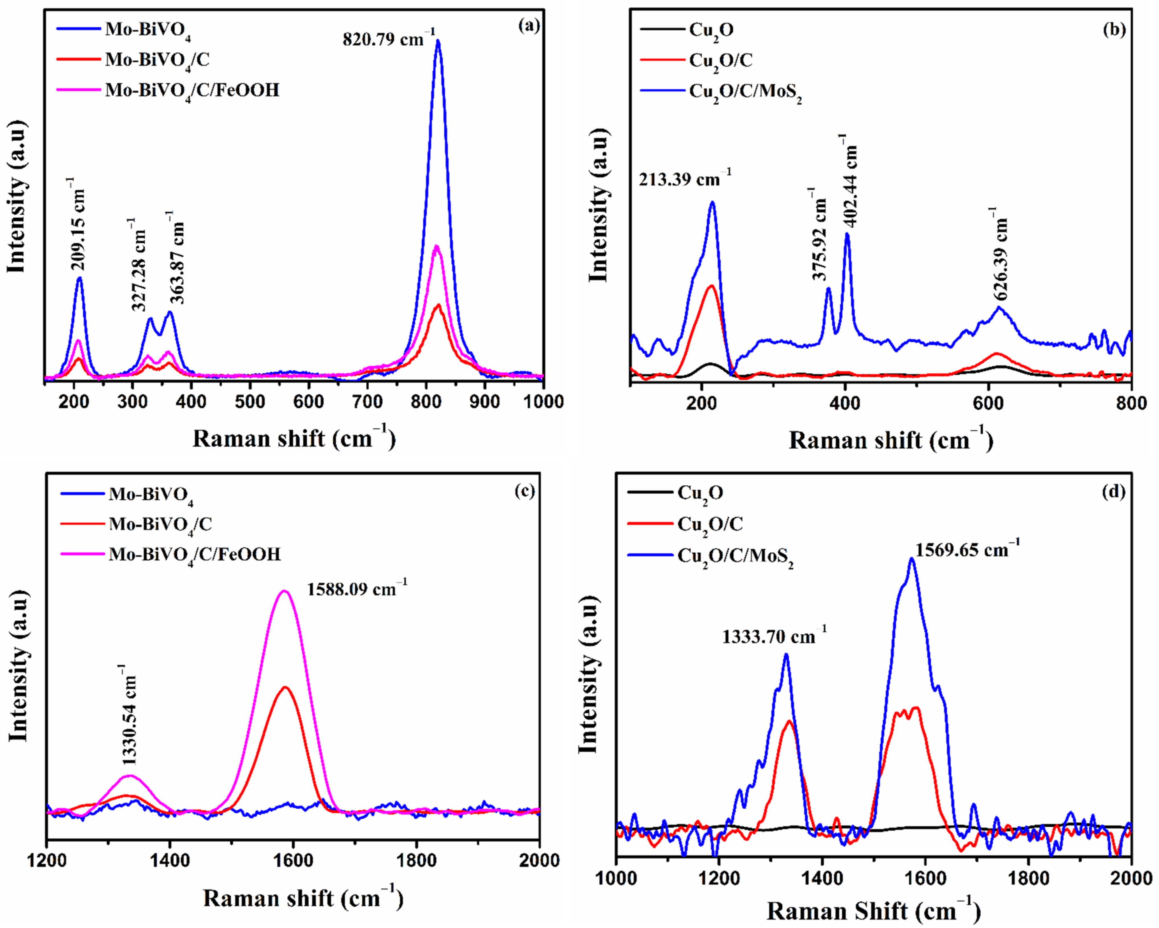
The Raman spectra of the photoanodes and photocathodes are shown in Figure 1a,b. The Raman spectra are useful in analyzing the molecular vibrations in the compounds. The BiVO4 photoanode exhibited signature peaks at 209.15 cm−1, 327.28 cm−1, 363.87 cm−1, and 820.79 cm−1, confirming the monoclinic scheelite phase of BiVO4. The presence of molybdenum doping was manifested as a slight shift in the peak from 823.83 cm−1 to 820.79 cm−1 due to the strain caused by molybdenum in place of vanadium in the crystal lattice, and the small peak at 881.51 cm−1 also represents the vibration of O-Mo-O (Figure S2a in the Supplementary Materials). No significant peaks related to FeOOH were observed. The Raman spectra of Cu2O photocathodes (Figure 1b) revealed the dominant peak at 213.39 cm−1, which corresponds to the second order Raman mode of Cu2O. A small hump-like peak at 626.39 cm−1 signified the infrared allowed mode of Cu2O. The presence of MoS2 was found from the peaks at 375.92 cm−1 and 402.44 cm−1 ascribed to the in-plane and out-plane modes of sulphur and molybdenum vibrations, respectively (Figure S2b) in Supplementary Materials.
The presence of a carbon layer in Mo-BiVO4/C and Mo-BiVO4/C/FeOOH photoanodes was confirmed by the presence of D-band and G-band peaks at 1330.54 cm−1 and 1588.09 cm−2, respectively, in Figure 1c. In Cu2O/C and Cu2O/C/MoS2 photocathodes, the carbon peaks were found at 1333.70 cm−1 and 1569.65 cm−1 in Figure 1d. The D-band represents disorder caused by out of plane vibrations of structural defects and G-band represents in-plane vibrations of sp2 bonded carbon in planar sheets [18]. The significance of Raman peaks on BiVO4 photoanodes and Cu2O photocathodes is tabulated in Tables S1 and S2, respectively in the Supplementary Materials.
The XRD spectra of prepared photoelectrodes are shown in Figure S1a,b in the Supplementary Materials. The results showed that the prepared photoanode exhibited a monoclinic scheelite structure and the prepared photocathode exhibited a cubic phase.
2.2. Morphological Analysis
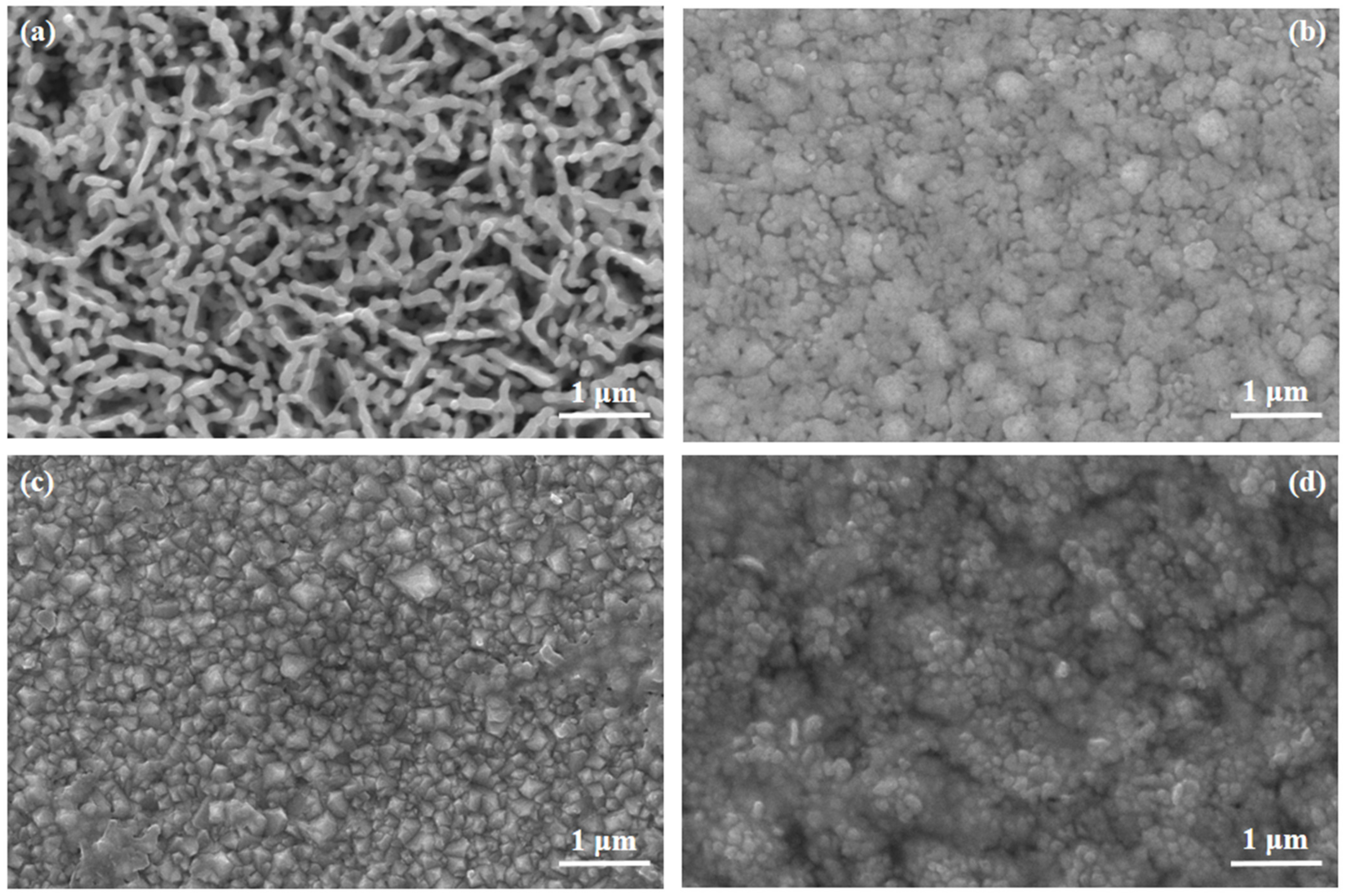
The FESEM surface morphology of the prepared photoelectrodes is shown in Figure 2. The morphology of the BiVO4 photoanode exhibited a dense nanosphere-like network morphology (Figure 2a). The presence of Mo doping was found by energy dispersive X-ray spectroscopy (Figure S4 in the Supplementary Materials). The SEM images also revealed the conformal coating of carbon layers both on the photoanode and photocathode. (Figure 2b). During the carbonization process, the glucose was initially dehydrated, followed by the formation of aromatic functional groups. The aromatic group decomposed as the temperature increased. Finally, the carbonization process formed a thin carbon layer. Carbon, by nature, is a stable material, so it can withstand any harsh environment. The energy dispersive mapping spectra are presented in Figure S4 in the Supplementary Materials. Figure 2c,d presents the top-view morphology of Cu2O photocathodes with and without a carbon layer. A compact coating of electrodeposited Cu2O was observed with smaller grains. The thickness of the Cu2O/C/MoS2 photocathode estimated from the FESEM image was ~1.745 µm (Figure S3d in the Supplementary Materials). From EDS mapping (Figure S5 in the Supplementary Materials), a conformal coating of carbon layer was confirmed. The top view FESEM micrograph and cross-sectional micrograph of Mo-BiVO4/C/FeOOH photoanode and Cu2O/C/MoS2 photocathode are presented in Figure S3a–d, which shows the cross sectional FESEM micrograph of Mo-BiVO4/C/FeOOH and Cu2O/C/MoS2 photocathode, respectively, in the Supplementary Materials. The thickness of the Mo-BiVO4/C/FeOOH photoanode was estimated to be around 520 nm.
2.3. Optical Analysis
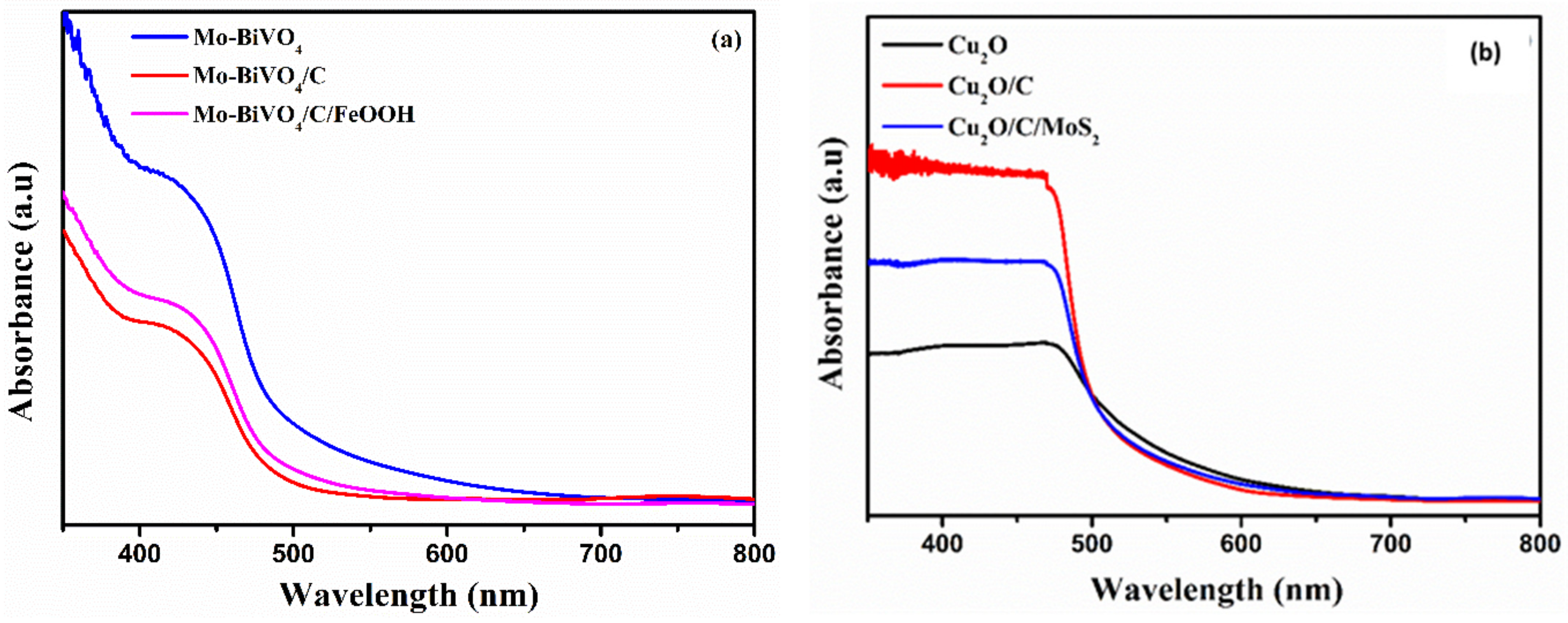
The optical characterization of the photoanodes and photocathodes is presented in Figure 3. The absorption spectra were recorded within the 400–800 nm visible wavelength range. The absorption edge of all photoanodes (Figure 3a) started at ~510 nm verifying the BiVO4 electronic structure. The corresponding bandgap of the photoanode was calculated using Tauc’s plot (Figure S6a–c) in the Supplementary Materials. [19]. The calculated bandgaps of the photoanodes were 2.58, 2.60, and 2.59 eV for Mo-BiVO4, Mo-BiVO4/C, and Mo-BiVO4/C/FeOOH, respectively [20]. The addition of FeOOH and a carbon layer slightly changed the absorption intensity and blue-shifted the bandgap. The transmittance of the photoanodes is presented in Figure S6g. As noticed from Figure S6g, the transmittance of all the photoanodes was within the range of 75–80%. Similarly, the UV-Vis response of Cu2O photocathodes in Figure 3b revealed the absorption edge starting at ~600 nm. The calculated bandgap from Tauc’s plot was ~2.32 eV (Figure S6d–f). The addition of a carbon layer and MoS2 co-catalyst blue-shifted the bandgap (2.46 and 2.44 eV) due to synergetic effects. From the optical analysis, it was concluded that the photoanode absorbs photons up to 510 nm and the photocathode absorbs photons between 510 nm and 600 nm as well as the remaining photons that are not absorbed by the photoanode.
2.4. PEC Performance
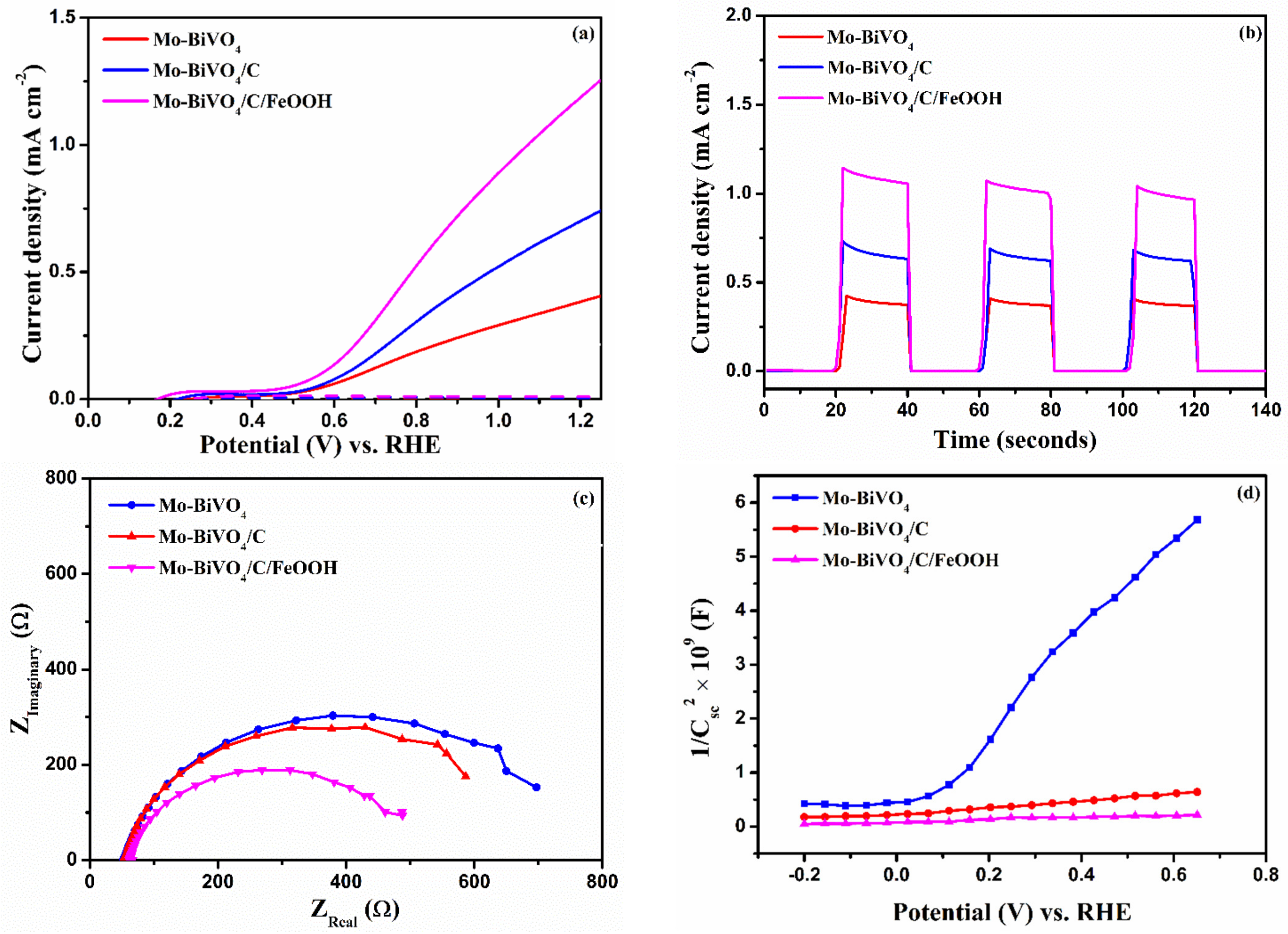
Figure 4a presents the LSV responses of the Mo-BiVO4, Mo-BiVO4/C, and Mo-BiVO4/C/FeOOH photoanodes. The carbon-protected sample exhibited a better photocurrent density of 0.74 mA cm−2 than the unprotected sample (0.40 mA cm−2) at 1.23 V vs. RHE. The onset potential of the carbon-protected sample was slightly shifted to the cathodic side. The increase in photocurrent and cathodic-shift in the onset potential of carbon-protected photoanodes indicates the significant role of carbon in minimizing the surface recombination by reducing surface defects in addition to protecting BiVO4 from electrolytes. The J vs. t curve at Figure 4b showed the proof of photocurrent generated at 1.23 V vs. RHE under chopped conditions. The J vs. t curve also showed no transient spikes when the light was turned on or off, confirming reduction in charge carrier recombination. The reduction in recombination was corroborated by photoluminescence spectroscopy (Figure S7a), in which the reduction in PL intensity was noticed for carbon-protected BiVO4 samples. The increase in photocurrent was further supported by the electrochemical impedance spectra (EIS), which showed minimal charge transfer resistance for carbon-coated samples (Figure 4c). The addition of co-catalyst FeOOH boosted the photocurrent further to 1.24 mA cm−2 at 1.23 V vs. RHE with a cathodic shift in onset potential to 0.41 V vs. RHE for Mo-BiVO4/C/FeOOH. Since the co-catalyst has the ability to reduce the overpotential, the photoanode Mo-BiVO4/C/FeOOH exhibited the best PEC performance among the prepared photoanodes. Similarly, the reduction in recombination is further corroborated by Mott–Schottky analysis (Figure 4d), which shows improved donor density and a cathodic shift in flat band potential for carbon-protected samples compared to bare photoanodes. Various efficiency parameters, such as the applied bias photon-to-current efficiency, charge separation, and injection efficiencies of Mo-BiVO4 photoanodes, are discussed in Section 2.2 in the Supplementary Materials (Figure S9). The results confirm that the charge separation and injection efficiency were higher for carbon protected BiVO4 with FeOOH as a co-catalyst. The stability of the Mo-BiVO4 and Mo-BiVO4/C/FeOOH photoanodes is shown in Figure S8 in the Supplementary Materials. The PEC parameters of photoanodes and photocathodes are tabulated in Table 1.
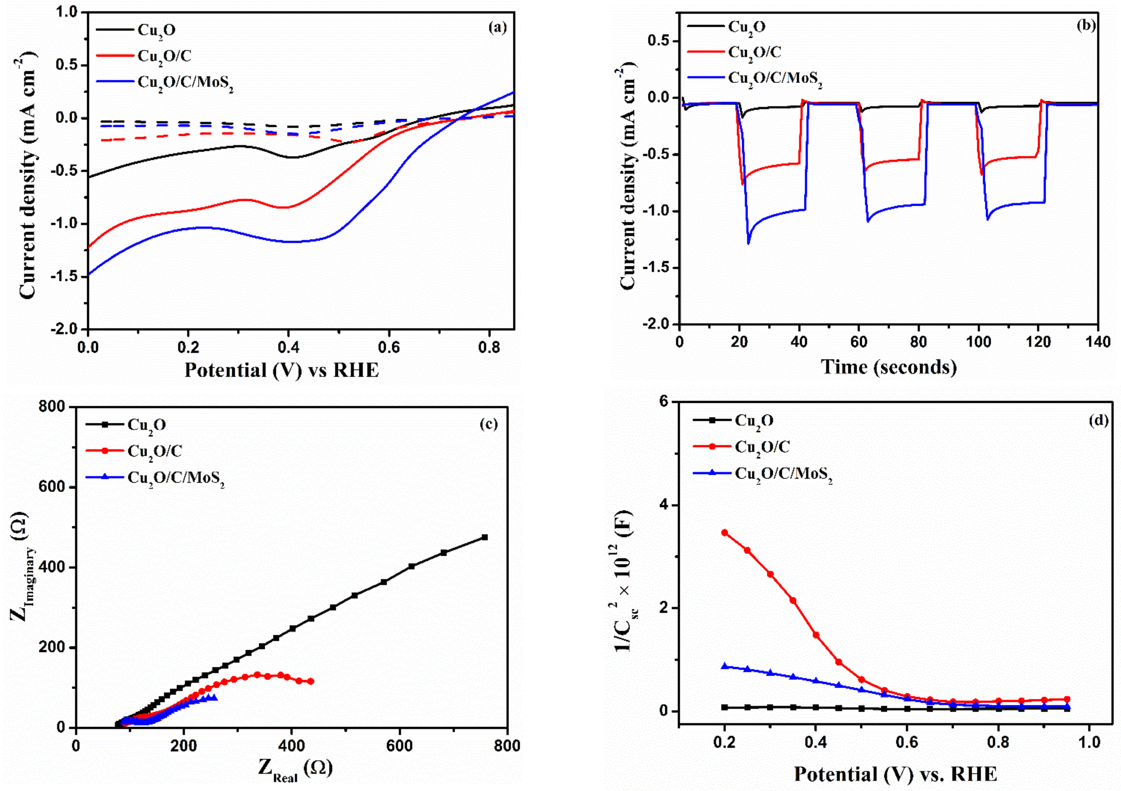
The PEC performance of the photocathode is shown in Figure 5. Cu2O is very sensitive to photocorrosion [21] in the presence of water under illumination. The protective layer plays a dominant role in protecting photocathodes and thus improving PEC performance. The LSV curves (Figure 5a) yielded a cathodic response to the photocathode with an applied bias. The current density of ~−0.55 mA cm−2 at 0 V vs. RHE was recorded for bare Cu2O. The main issue for the low current density of Cu2O is the reduction of cuprous oxide to metallic copper upon illumination. The deposition of a carbon protective layer on Cu2O/C improved the current density to ~−1.21 mA cm−2 at 0 V vs. RHE. The significance of the carbon layer in the photocathode is to protect the photocathode from photocorrosion and promote rapid charge transfer to the surface. The addition of drop-casted MoS2 on the Cu2O/C photocathode attained a maximum current density of ~−1.48 mA cm−2 at 0 V vs. RHE with an onset potential of 0.74 V vs. RHE as a result of the protective nature of carbon and enhanced HER activity of MoS2 catalyst. The J vs. t plot is shown in Figure 5b, indicating the generation of photocurrent as soon as the light is on. The plot also indicated the suppression of charge carrier recombination from the reduction in transient spikes during on and off cycles. The EIS study was also recorded for photocathodes under illumination at the water reduction potential (0 V vs. RHE) and presented in Figure 5c. The charge transfer resistance measured from the fitting using Scribner’s Z-View software exhibited the least resistance for carbon-coated samples compared to bare photocathodes. The equivalent circuit was constructed using the same software for both photoelectrodes using the instant fit option, and the equivalent circuit is shown in Figure S10 in the Supplementary Materials. The reduction in charge carrier recombination of carbon-protected Cu2O was further confirmed with PL spectra (Figure S7b in the Supplementary Materials) showing reduced PL intensity compared to bare Cu2O. The flat band potential, from Mott–Schottky analysis (Figure 5d), of carbon coated samples shifted more towards the anodic side compared to bare photocathodes (anodic shift from 0.565 V vs. RHE for bare Cu2O to 0.74 V vs. RHE for Cu2O/C/MoS2), implying that reduction in recombination as a result of minimized surface defects and suppression of photocorrosion. The increase in the EFB also indicates higher band bending and a larger space charge region potential. The detailed explanation about Mott–Schottky plots of photoanodes and photocathodes has been included in Section 2.4 (Figure S11) in the Supplementary Materials. The stability of the Cu2O and Cu2O/C/MoS2 photoanodes is shown in Figure S8 in the Supplementary Materials.
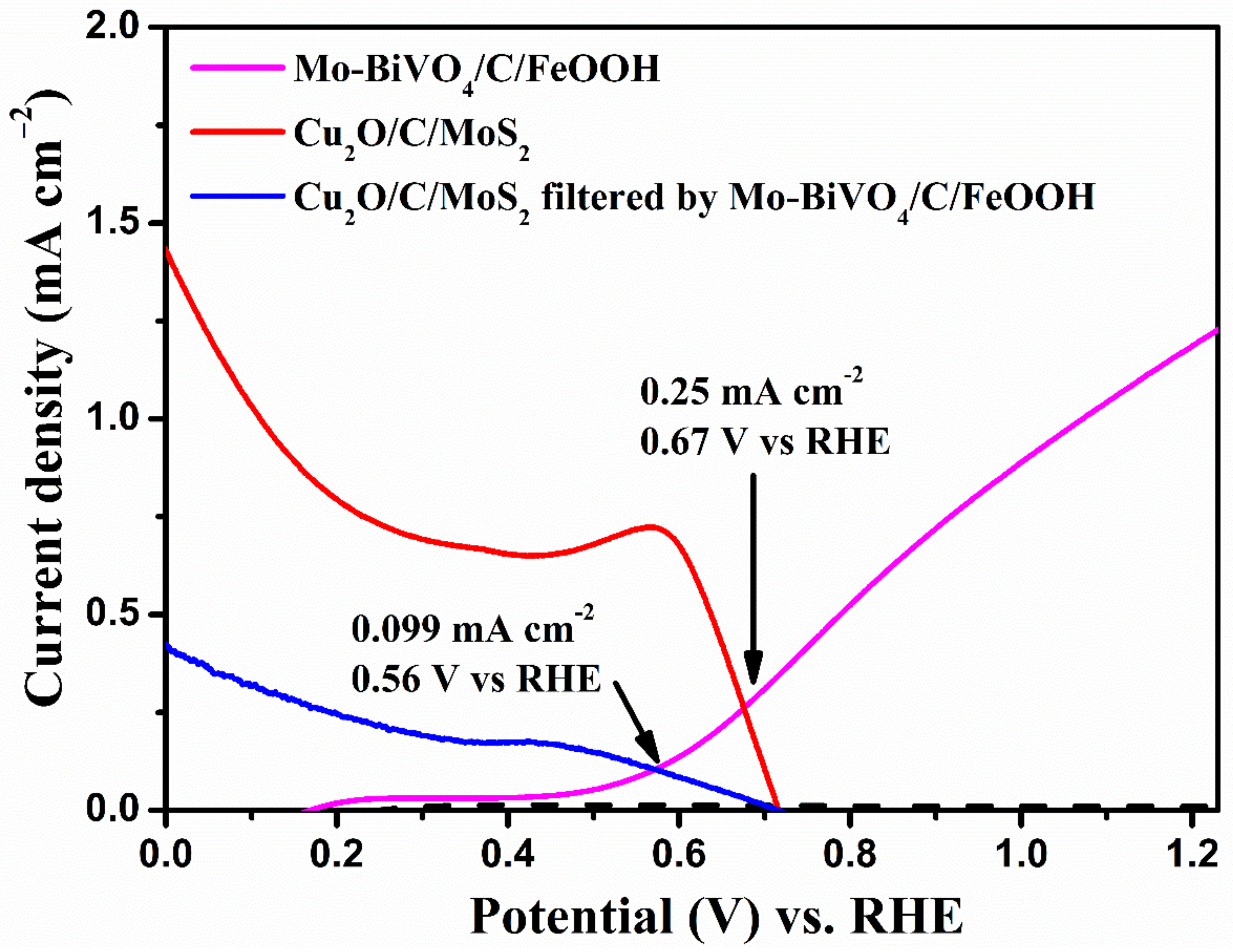
From the individual photoelectrode response, we measured the operating potential and current density of the tandem cell as shown in Figure 6. On overlaying the LSV responses of the Mo-BiVO4/C/FeOOH photoanode and the Cu2O/C/MoS2 photocathode, the operating voltage and current density of 0.67 V vs. RHE and 0.25 mA cm−2 were obtained. In order to mimic the absorption of a tandem PEC cell, Cu2O/C/MoS2 filtered by a Mo-BiVO4/C/FeOOH photoanode was also overlaid to find the operating point, and the obtained values were 0.56 V vs. RHE and 0.099 mA cm−2. The reduction in operating points is obvious because the photocathode absorbs light that is transmitted by the photoanode. The overlay curve for bare BiVO4 and Cu2O is shown in Figure S12 in the Supplementary Materials.
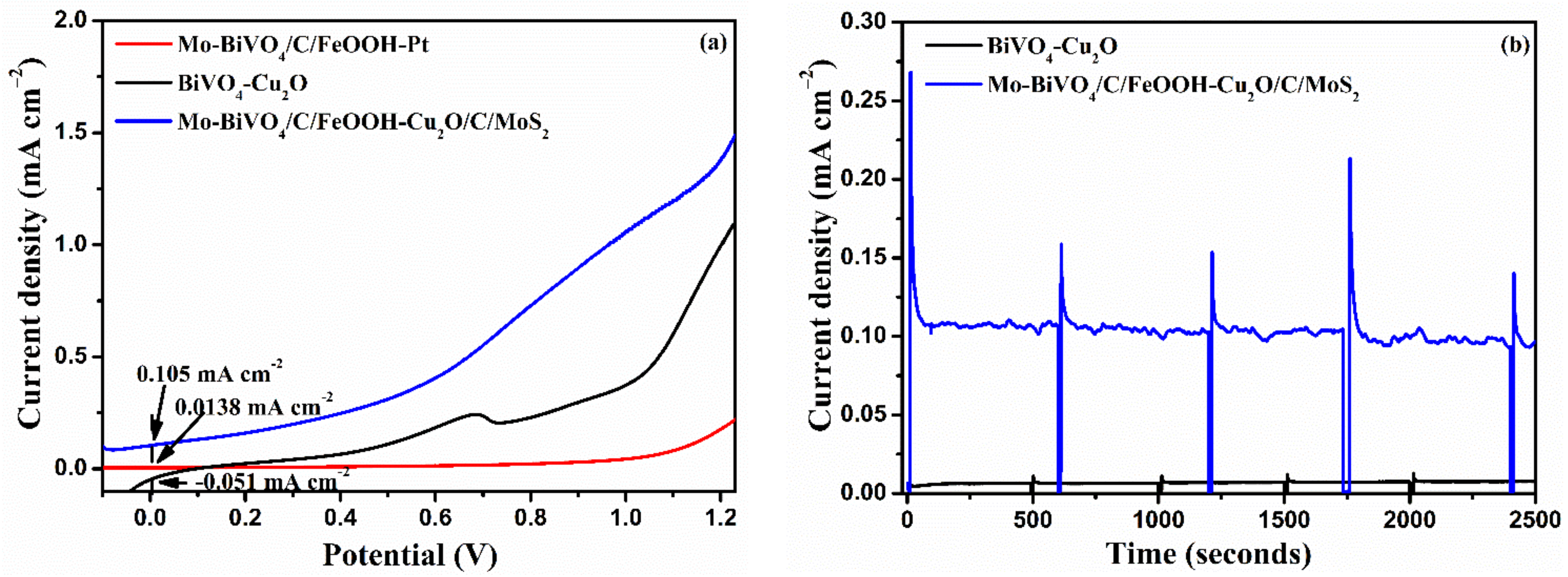
The tandem cell was constructed by placing the photoanode (top) at a 2 cm distance from the photocathode, face to face (Figure S13). The AM 1.5G light illuminated the photoanode on the back side and the photocathode on the front side. Photoelectrochemical tests were analyzed in a two-electrode setup using 0.1 M Na2SO4 (pH 6), electrolyte, which was purged with nitrogen for 30 min. The non-zero operating point obtained in the overlay plot implies the possibility of operation without any external bias. Figure 7a shows the LSV of a Mo-BiVO4/C/FeOOH-Pt, BiVO4-Cu2O, and Mo-BiVO4/C/FeOOH-Cu2O/C/MoS2 tandem PEC cell. In the LSV curves, the prepared tandem cells produced negligible current density in the dark. The Mo-BiVO4/C/FeOOH-Pt cell used for comparison produced a negligible current density up to 1 V, and the unassisted photocurrent was close to 0.0138 mA cm−2. The positive current density of 0.1 mA cm−2 at 0 V vs. RHE observed for the Mo-BiVO4/C/FeOOH-Cu2O/C/MoS2 tandem cell implies that cell could produce photocurrent without an external bias. The unprotected sample produced an unassisted photocurrent density of −0.051 mA cm−2 due to the instability of the photocathodes as well as the possibility of surface defects existing on the surface. The chronoamperometry measurements recorded at zero bias for 3000 s (Figure 7b) further confirmed the stable nature of carbon protected samples with negligible decay during the testing window.
3. Materials and Methods
This work was a continuation of our previous work [17], and the preparation of materials used in the tandem cell has been explained in detail except for the carbon protective layer. We have summarized the preparation methods briefly here.
3.1. Deposition of BiVO4 Photoanodes
The FTO substrates with a surface resistivity of ~7 Ω sq.−1 was ultrasonically cleaned with acetone, isopropanol, and ethanol to remove the impurities from the FTO substrates. A mixture of 4.6 mL of acetylacetone and 0.4 mL of acetic acid was prepared as solution, to which 0.173 g of bismuth nitrate pentahydrate and 0.0097 g of vanadyl acetylacetonate were added. Then, the precursor solution was spin coated on cleaned FTO substrates at 1000 RPM for 30 s. Maximum performance was obtained for coating four layers of BiVO4 [22]. After each spin-coated layer, the photoanodes were annealed at 450 °C for 15 min. Finally, the substrates were annealed at 450 °C for 2 h in a muffle furnace [23]. For Mo doping, three weight percentage (3 at. %) of bis(acetylacetonate)dioxomolybdenum(VI) was added to the precursor solution, and the same procedure was followed.
3.2. Deposition of FeOOH
FeOOH is an oxygen evolution reaction (OER) catalyst deposited by the electrodeposition method. Briefly 0.1 M iron sulphate hexahydrate aqueous solution is prepared. Then, a constant potential of 1.2 V vs. Ag/AgCl was maintained for 5 min. The as-deposited Mo-BiVO4/C/FeOOH was rinsed with a copious amount of DI water and dried at room temperature [24].
3.3. Deposition of Cu2O Photocathode
Cu2O photocathode was electrodeposited using a 0.4 M copper sulphate pentahydrate solution in a 3 M lactic acid solution. Then, the pH of the solution was varied frm 9 to 11 using a 5 M sodium hydroxide solution. Cu2O photocathode was electrodeposited using a typical 3-electrode setup under a constant potential of −0.3 V vs. Ag/AgCl for 1 h. Finally, the as-deposited Cu2O photocathode was rinsed with DI water and dried [25].
3.4. Deposition of a MoS2 Layer
Initially, 0.242 g of sodium molybdate dihydrate and 0.381 g of thiourea were mixed in 60 mL of DI water. The solution was transferred to a 100 mL Teflon-lined stainless steel autoclave, which was kept at 200 °C for 24 h. The black precipitate was washed with DI water and ethanol sequentially and dried at 70 °C overnight [26]. For deposition of MoS2, 1 mg/mL of as-prepared MoS2 was dispersed in n-methyl-2-pyrrolidone and ultrasonicated continuously for 3 h. After the ultrasonication process, the top layer of the solution (supernatant solution) was transferred to another sample vial and drop-cast onto Cu2O/C photocathodes. The photocathode was annealed at 200 °C for 1 h.
3.5. Deposition of the Carbon Layer
A Carbon layer on Mo-BiVO4 photoanode/Cu2O photocathode was achieved by the carbonization of glucose in the N2 atmosphere. Briefly, the as-prepared photoanode/photocathode were immersed in 50 mL of glucose solution (3 mg/mL) overnight and dried at room temperature. Then, the photoanode/ photocathode was kept in a tubular furnace at 400 °C for 4 h in a nitrogen atmosphere. The slow heating melts and carbonizes glucose into a thin carbon layer [15].
3.6. Material Characterization
Raman spectra were obtained using a Horiba Raman microscope (Kyoto, Japan) with a 532 nm green laser as the source at 25% laser power. A field emission scanning electron microscope (FESEM) micrograph was obtained using a FEI Quanta 250 FEG (Hillsboro, Oregon, USA) operated at an accelerating voltage of 20 kV. UV-Vis spectra were obtained using a UV-Vis spectrophotometer (Specord plus, Analytik jena GmBH, Jena, Germany) in the range of 300–800 nm. X-ray diffraction patterns were obtained using an X-ray diffractometer (D8 Advanced, Bruker, Billerica, Massachusetts, USA) with Cu-kα radiation with λ = 1.5418 Å.
3.7. Photoelectrochemical Measurements
Photoelectrochemical performance was recorded using an AMETEK PARSTAT (Berwyn, PA, USA) advanced electrochemical workstation. The illumination source was an oriel class AAA solar simulator with spectral irradiance using an AM 1.5 G filter corrected to a power intensity of 100 mW cm−2. A three-electrode setup was used in PEC testing, with BiVO4 photoanodes/Cu2O photocathodes as the working electrodes, platinum wire as a counter electrode, and Ag/AgCl (satd. KCl) as a reference electrode. The electrolyte used for PEC testing was 0.1 M Na2SO4 (pH 6), which was purged with nitrogen for 30 min before starting the PEC test. Linear sweep voltammetry (LSV) was performed at a scan rate of 20 mVs.−1 for both the photoanode and the photocathode. Electrochemical impedance spectroscopy (EIS) was performed under illumination (100 mW cm−2) with the frequency ranges of 105 Hz to 1 Hz using an AC signal amplitude of 10 mV. A Mott–Schottky plot was obtained at 1 kHz frequency under dark conditions. The active area of the photoanode and photocathode was 1 cm2. The potential of the working electrode was marked with the reference electrode, and it was converted into the reversible hydrogen electrode (RHE) potential scale using the formula, ERHE = EAg/AgCl + 0.059pH + E0Ag/AgCl.
Tandem measurements were performed in 0.1 M Na2SO4 (pH 6) purged with nitrogen for 30 min. The distance between the photoanode and the photocathode was kept at 2 cm. The active area of the cell was restricted to 1 cm2. The PEC performance of the tandem cell was recorded in a 2-electrode configuration using an AMETEK PARSTAT advanced electrochemical workstation. Oriel’s class AAA solar simulator with spectral irradiance using an AM 1.5 G filter corrected to a power intensity of 100 mW cm−2 was used as the illumination source. The stability of the tandem cell was recorded under a zero-bias condition.
4. Conclusions
We constructed and demonstrated the PEC performance of a Mo-BiVO4/C/FeOOH–Cu2O/C/MoS2 tandem PEC cell. The prepared carbon protective layer using the glucose carbonization process yielded a robust conformal coating both on the photoanode and the photocathode. The individual photoanode and photocathode with a carbon protective layer delivered better current density than bare photoelectrodes due to the ability of carbon to protect and facilitate charge transfer as confirmed by the EIS spectra. The flat band potential shifting to the cathodic side for photoanodes and the anodic side for photocathodes signified the improvement in band bending and space charge potential. In addition to the protective layer, the addition of co-catalysts reduced the overpotential, as manifested in a shift in the onset potential of the LSV spectra. The model semiconductor oxides tandem PEC cell Mo-BiVO4/C/FeOOH-Cu2O/C/MoS2 produced a stable current density of 0.10 mA cm−2 in a 2-electrode setup for 3000 s and was higher than the tandem cell without a carbon protective layer. A carbon protective layer can be a viable option to protect photoelectrodes and improve the PEC performance.
Supplementary Materials
The following supporting information can be downloaded at: https://0-www-mdpi-com.brum.beds.ac.uk/article/10.3390/catal13010144/s1, Figure S1: (a) XRD spectra of Mo-BiVO4, Mo-BiVO4/C and Mo-BiVO4/C/FeOOH photoanode and (b) Cu2O, Cu2O/C and Cu2O/C/MoS2 photocathodes, Figure S2: (a) Zoomed Raman Spectra of BiVO4 photoanodes which presents the blue shift in the peak at 823.24 cm-1 to 820.79 cm-1 due to doping of Molybdenum (b) Zoomed Raman Spectra of Cu2O/C/MoS2 photocathode which confirms the presence of MoS2 on Cu2O/C/MoS2 photocathode, Figure S3: FESEM micrograph of (a) Mo-BiVO4/C/FeOOH photoanode, (b) Cu2O/C/MoS2 photocathode and Cross sectional FESEM micrograph of (c) Mo-BiVO4/TiO2/FeOOH photoanode and (d) Cu2O/TiO2/MoS2 photocathode, Figure S4: EDS colour mapping of Mo-BiVO4/C/FeOOH photoanode, Figure S5: EDS colour mapping of Cu2O/C/MoS2 photocathode, Figure S6: Extrapolation of (a) Mo-BiVO4, (b) Mo-BiVO4/C, (c) Mo-BiVO4/C/FeOOH photoanodes and (d) Cu2O, (e) Cu2O/C and (f) Cu2O/C/MoS2 photocathodes to find the bandgap, (g), Transmittance of BiVO4, Mo-BiVO4, Mo-BiVO4/C, Mo-BiVO4/C/FeOOH photoanodes, Figure S7: Photoluminescence spectra of (a) Mo-BiVO4, Mo-BiVO4/C photoanodes and (b) Cu2O, Cu2O/C photocathodes, Figure S8: Chronoamperometry (J vs t) stability tests of (a) Mo-BiVO4, Mo-BiVO4/C/FeOOH photoanodes performed at 1.23 V vs RHE, (b) Cu2O, Cu2O/C/MoS2 photocathodes performed at 0 V vs RHE using 0.1 M Na2SO4 (pH 6) electrolyte in AM 1.5 G illumination with power intensity of 100 mW cm-2, Figure S9: (a) Light harvesting efficiency with respect to standard solar spectrum, (b) LSV curves using 0.1 M Na2SO3 + 0.1 M Na2SO4 (pH 6) electrolyte, (c) Charge injection efficiency, (d) Charge separation efficiency and (e) Applied bias photon-to-current efficiency of Mo-BiVO4, Mo-BiVO4/C and Mo-BiVO4/C/FeOOH photoanodes, Figure S10: EIS equivalent circuit of BiVO4 photoanodes and Cu2O photocathodes, Figure S11: Mott-Schottky plot of (a) Mo-BiVO4, (b) Mo-BiVO4/C and (c) Mo-BiVO4/C/FeOOH photoanodes, (d) Cu2O and (e) Cu2O/C and (f) Cu2O/C/MoS2 photocathodes tested in dark condition at 1 kHz frequency in 0.1 M Na2SO4 (pH 6), Figure S12: Overlayer LSV curves of BiVO4 photoanodes and Cu2O photocathodes tested in 0.1 M Na2SO4 (pH 6) using AM 1.5 G light source with power intensity of 100 mW cm-2, Figure S13: Photographs of of Mo-BiVO4/C/FeOOH-Cu2O/C/Mos2 tandem cell. Table S1: Tabulation of significance of BiVO4 photoanodes. Table S2: Tabulation of significance of Cu2O photocathodes, Table S3: Comparison of Mo-BiVO4/C/FeOOH photoanode and Cu2O/C/MoS2 photocathode with works performed using carbon based materials. Ref from [27,28,29,30,31,32,33,34,35,36,37,38,39,40,41,42,43,44,45].
Author Contributions
S.S.R.R.: methodology and writing-original draft. N.G.A.: funding acquisition and validation. R.S.: methodology, writing and review—original draft, funding acquisition, and validation. All authors have read and agreed to the published version of the manuscript.
Funding
This work was supported by DST—SERB, Government of India. The authors are grateful to DST—SERB project EMR/2017/001185 for the financial support.
Data Availability Statement
Not applicable.
Acknowledgments
We thank the Centre for Nanotechnology Research (CNR), Vellore Institute of Technology for the lab facility and the Central university of Tamil Nadu, Thiruvarur for PL facility.
Conflicts of Interest
The authors declare that they have no known competing financial interest or personal relationships that could have appeared to influence the work reported in this paper.
References
- Liao, C.H.; Huang, C.W.; Wu, J.C.S. Hydrogen Production from Semiconductor-Based Photocatalysis via Water Splitting. Catalysts 2012, 2, 490–516. [Google Scholar] [CrossRef] [Green Version]
- Møller, K.T.; Jensen, T.R.; Akiba, E.; Li, H. Hydrogen—A Sustainable Energy Carrier. Prog. Nat. Sci. Mater. Int. 2017, 27, 34–40. [Google Scholar] [CrossRef]
- Bornoz, P.; Abdi, F.F.; Tilley, S.D.; Dam, B.; Van De Krol, R.; Graetzel, M.; Sivula, K. A Bismuth Vanadate-Cuprous Oxide Tandem Cell for Overall Solar Water Splitting. J. Phys. Chem. C 2014, 118, 16959–16966. [Google Scholar] [CrossRef]
- Prévot, M.S.; Sivula, K. Photoelectrochemical Tandem Cells for Solar Water Splitting. J. Phys. Chem. C 2013, 117, 17879–17893. [Google Scholar] [CrossRef]
- Zhao, M.; Chen, T.; He, B.; Hu, X.; Huang, J.; Yi, P.; Wang, Y.; Chen, Y.; Li, Z.; Liu, X. Photothermal Effect-Enhanced Photoelectrochemical Water Splitting of a BiVO4 photoanode Modified with Dual-Functional Polyaniline. J. Mater. Chem. A 2020, 8, 15976–15983. [Google Scholar] [CrossRef]
- Bagal, I.V.; Chodankar, N.R.; Hassan, M.A.; Waseem, A.; Johar, M.A.; Kim, D.H.; Ryu, S.W. Cu2O as an Emerging Photocathode for Solar Water Splitting—A Status Review. Int. J. Hydrog. Energy 2019, 44, 21351–21378. [Google Scholar] [CrossRef]
- Arunachalam, P.; Nagai, K.; Amer, M.S.; Ghanem, M.A.; Ramalingam, R.J.; Al-Mayouf, A.M. Recent Developments in the Use of Heterogeneous Semiconductor Photocatalyst Based Materials for a Visible-Light-Inducedwater-Splitting System-a Brief Review. Catalysts 2021, 11, 160. [Google Scholar] [CrossRef]
- Zachäus, C.; Abdi, F.F.; Peter, L.M.; Van De Krol, R. Photocurrent of BiVO4 Is Limited by Surface Recombination, Not Surface Catalysis. Chem. Sci. 2017, 8, 3712–3719. [Google Scholar] [CrossRef] [Green Version]
- Moehl, T.; Suh, J.; Sévery, L.; Wick-Joliat, R.; Tilley, S.D. Investigation of (Leaky) ALD TiO2 Protection Layers for Water-Splitting Photoelectrodes. ACS Appl. Mater. Interfaces 2017, 9, 43614–43622. [Google Scholar] [CrossRef]
- Yoon, K.; Lee, J.H.; Kang, J.; Kang, J.; Moody, M.J.; Hersam, M.C.; Lauhon, L.J. Metal-Free Carbon-Based Nanomaterial Coatings Protect Silicon Photoanodes in Solar Water-Splitting. Nano Lett. 2016, 16, 7370–7375. [Google Scholar] [CrossRef]
- Prakash, J.; Prasad, U.; Alexander, R.; Bahadur, J.; Dasgupta, K.; Kannan, A.N.M. Photoelectrochemical Solar Water Splitting: The Role of the Carbon Nanomaterials in Bismuth Vanadate Composite Photoanodes toward Efficient Charge Separation and Transport. Langmuir 2019, 35, 14492–14504. [Google Scholar] [CrossRef]
- Han, X.; Wei, Y.; Su, J.; Zhao, Y. Low-Cost Oriented Hierarchical Growth of BiVO4/RGO/NiFe Nanoarrays Photoanode for Photoelectrochemical Water Splitting. ACS Sustain. Chem. Eng. 2018, 6, 14695–14703. [Google Scholar] [CrossRef]
- Zeng, G.; Deng, Y.; Yu, X.; Zhu, Y.; Fu, X.; Zhang, Y. Ultrathin G-C3N4 as a Hole Extraction Layer to Boost Sunlight-Driven Water Oxidation of BiVO4-Based Photoanode. J. Power Sources 2021, 494, 229701. [Google Scholar] [CrossRef]
- Reddy, D.A.; Kim, Y.; Shim, H.S.; Reddy, K.A.J.; Gopannagari, M.; Praveen Kumar, D.; Song, J.K.; Kim, T.K. Significant Improvements on BiVO4@CoPi Photoanode Solar Water Splitting Performance by Extending Visible-Light Harvesting Capacity and Charge Carrier Transportation. ACS Appl. Energy Mater. 2020, 3, 4474–4483. [Google Scholar] [CrossRef]
- Kunturu, P.P.; Huskens, J. Efficient Solar Water Splitting Photocathodes Comprising a Copper Oxide Heterostructure Protected by a Thin Carbon Layer. ACS Appl. Energy Mater. 2019, 2, 7850–7860. [Google Scholar] [CrossRef] [Green Version]
- Kaneza, N.; Shinde, P.S.; Ma, Y.; Pan, S. Photoelectrochemical Study of Carbon-Modified p-Type Cu2O Nanoneedles and n-Type TiO2-x Nanorods for Z-Scheme Solar Water Splitting in a Tandem Cell Configuration. RSC Adv. 2019, 9, 13576–13585. [Google Scholar] [CrossRef] [Green Version]
- Sitaaraman, S.R.; Nirmala Grace, A.; Sellappan, R. Photoelectrochemical Performance of a Spin Coated TiO2 Protected BiVO4-Cu2O Thin Film Tandem Cell for Unassisted Solar Water Splitting. RSC Adv. 2022, 12, 31380–31391. [Google Scholar] [CrossRef]
- Chhowalla, M.; Ferrari, A.C.; Robertson, J.; Amaratunga, G.A.J. Evolution of Sp2 Bonding with Deposition Temperature in Tetrahedral Amorphous Carbon Studied by Raman Spectroscopy. Appl. Phys. Lett. 2000, 76, 1419–1421. [Google Scholar] [CrossRef]
- Jubu, P.R.; Yam, F.K.; Igba, V.M.; Beh, K.P. Tauc-Plot Scale and Extrapolation Effect on Bandgap Estimation from UV–Vis–NIR Data—A Case Study of β-Ga2O3. J. Solid State Chem. 2020, 290, 121576. [Google Scholar] [CrossRef]
- Zhang, X.; Li, M.; Liu, C.; Zhang, Z.; Zhang, F.; Liu, Q. Enhanced the Efficiency of Photocatalytic Degradation of Methylene Blue by Construction of Z-Scheme g-C3N4/BiVO4 Heterojunction. Coatings 2021, 11, 1027. [Google Scholar] [CrossRef]
- Kumar, M.; Meena, B.; Subramanyam, P.; Suryakala, D.; Subrahmanyam, C. Emerging Copper-Based Semiconducting Materials for Photocathodic Applications in Solar Driven Water Splitting. Catalysts 2022, 12, 1198. [Google Scholar] [CrossRef]
- Luo, W.; Li, Z.; Yu, T.; Zou, Z. Effects of Surface Electrochemical Pretreatment on the Photoelectrochemical Performance of Mo-Doped BiVO 4. J. Phys. Chem. C 2012, 116, 5076–5081. [Google Scholar] [CrossRef]
- Hilliard, S.; Friedrich, D.; Kressman, S.; Strub, H.; Artero, V.; Laberty-Robert, C. Solar-Water-Splitting BiVO4 Thin-Film Photoanodes Prepared By Using a Sol-Gel Dip-Coating Technique. ChemPhotoChem 2017, 1, 273–280. [Google Scholar] [CrossRef]
- Zhang, B.; Wang, L.; Zhang, Y.; Ding, Y.; Bi, Y. Ultrathin FeOOH Nanolayers with Abundant Oxygen Vacancies on BiVO4 Photoanodes for Efficient Water Oxidation. Angew. Chemie Int. Ed. 2018, 57, 2248–2252. [Google Scholar] [CrossRef] [PubMed]
- Bai, S.; Liu, J.; Cui, M.; Luo, R.; He, J.; Chen, A. Two-Step Electrodeposition to Fabricate the p-n Heterojunction of a Cu2O/BiVO4 Photoanode for the Enhancement of Photoelectrochemical Water Splitting. Dalt. Trans. 2018, 47, 6763–6771. [Google Scholar] [CrossRef]
- Zhao, Y.F.; Yang, Z.Y.; Zhang, Y.X.; Jing, L.; Guo, X.; Ke, Z.; Hu, P.; Wang, G.; Yan, Y.M.; Sun, K.N. Cu2O Decorated with Cocatalyst MoS2 for Solar Hydrogen Production with Enhanced Efficiency under Visible Light. J. Phys. Chem. C 2014, 118, 14238–14245. [Google Scholar] [CrossRef]
- Guo, M.; He, Q.; Wang, A.; Wang, W.; Fu, Z. A Novel, Simple and Greenway to Fabricate BiVO4 with Excellent Photocatalytic Activity and Its Methylene Blue Decomposition Mechanism. Crystals 2016, 6, 81. [Google Scholar] [CrossRef] [Green Version]
- Rohloff, M.; Anke, B.; Zhang, S.; Gernert, U.; Scheu, C.; Lerch, M.; Fischer, A. Mo-Doped BiVO4 Thin Films-High Photoelectrochemical Water Splitting Performance Achieved by a Tailored Structure and Morphology. Sustain. Energy Fuels 2017, 1, 1830–1846. [Google Scholar] [CrossRef]
- Wang, X.; Li, G.; Ding, J.; Peng, H.; Chen, K. Facile Synthesis and Photocatalytic Activity of Monoclinic BiVO 4 Micro/Nanostructures with Controllable Morphologies. Mater. Res. Bull. 2012, 47, 3814–3818. [Google Scholar] [CrossRef]
- Aktar, A.; Ahmmed, S.; Hossain, J.; Ismail, A.B.M. Solution-Processed Synthesis of Copper Oxide (CuxO) Thin Films for Efficient Photocatalytic Solar Water Splitting. ACS Omega 2020, 5, 25125–25134. [Google Scholar] [CrossRef]
- Sahoo, D.; Kumar, B.; Sinha, J.; Ghosh, S.; Roy, S.S.; Kaviraj, B. Cost Effective Liquid Phase Exfoliation of MoS2 Nanosheets and Photocatalytic Activity for Wastewater Treatment Enforced by Visible Light. Sci. Rep. 2020, 10, 10759. [Google Scholar] [CrossRef]
- Patil, S.S.; Mali, M.G.; Hassan, M.A.; Patil, D.R.; Kolekar, S.S.; Ryu, S.W. One-Pot in Situ Hydrothermal Growth of BiVO4/Ag/RGO Hybrid Architectures for Solar Water Splitting and Environmental Remediation. Sci. Rep. 2017, 7, 8404. [Google Scholar] [CrossRef] [Green Version]
- Zeng, G.; Hou, L.; Zhang, J.; Zhu, J.; Yu, X.; Fu, X.; Zhu, Y.; Zhang, Y. FeOOH/RGO/BiVO4 Photoanode for Highly Enhanced Photoelectrochemical Water Splitting Performance. ChemCatChem 2020, 12, 3769–3775. [Google Scholar] [CrossRef]
- Li, S.; Jiang, Y.; Jiang, W.; Zhang, Y.; Pan, K.; Wang, S.; Hu, C.; Zhang, L.H.; Xia, L. In-Situ Generation of g-C3N4 on BiVO4 Photoanode for Highly Efficient Photoelectrochemical Water Oxidation. Appl. Surf. Sci. 2020, 523, 146441. [Google Scholar] [CrossRef]
- Hamdani, I.R.; Bhaskarwar, A.N. Cu2O Nanowires Based P-n Homojunction Photocathode for Improved Current Density and Hydrogen Generation through Solar-Water Splitting. Int. J. Hydrog. Energy 2021, 46, 28064–28077. [Google Scholar] [CrossRef]
- Hankin, A.; Bedoya-Lora, F.E.; Alexander, J.C.; Regoutz, A.; Kelsall, G.H. Flat Band Potential Determination: Avoiding the Pitfalls. J. Mater. Chem. A 2019, 7, 26162–26176. [Google Scholar] [CrossRef] [Green Version]
- Yang, Y.; Xu, D.; Wu, Q.; Diao, P. Cu2O/CuO Bilayered Composite as a High-Efficiency Photocathode for Photoelectrochemical Hydrogen Evolution Reaction. Sci. Rep. 2016, 6, 35158. [Google Scholar] [CrossRef] [Green Version]
- Tayebi, M.; Lee, B.K. The Effects of W/Mo-Co-Doped BiVO4 Photoanodes for Improving Photoelectrochemical Water Splitting Performance. Catal. Today 2021, 361, 183–190. [Google Scholar] [CrossRef]
- Tian, C.M.; Li, W.W.; Lin, Y.M.; Yang, Z.Z.; Wang, L.; Du, Y.G.; Xiao, H.Y.; Qiao, L.; Zhang, J.Y.; Chen, L.; et al. Electronic Structure, Optical Properties, and Photoelectrochemical Activity of Sn-Doped Fe2O3 Thin Films. J. Phys. Chem. C 2020, 124, 12548–12558. [Google Scholar] [CrossRef]
- Jessl, S.; Rongé, J.; Copic, D.; Jones, M.A.; Martens, J.; De Volder, M. Honeycomb-Shaped Carbon Nanotube Supports for BiVO4 Based Solar Water Splitting. Nanoscale 2019, 11, 22964–22970. [Google Scholar] [CrossRef]
- Ye, K.H.; Wang, Z.; Gu, J.; Xiao, S.; Yuan, Y.; Zhu, Y.; Zhang, Y.; Mai, W.; Yang, S. Carbon Quantum Dots as a Visible Light Sensitizer to Significantly Increase the Solar Water Splitting Performance of Bismuth Vanadate Photoanodes. Energy Environ. Sci. 2017, 10, 772–779. [Google Scholar] [CrossRef]
- Wang, M.; Wang, Z.; Zhang, B.; Jiang, W.; Bao, X.; Cheng, H.; Zheng, Z.; Wang, P.; Liu, Y.; Whangbo, M.H.; et al. Enhancing the Photoelectrochemical Water Oxidation Reaction of BiVO4 Photoanode by Employing Carbon Spheres as Electron Reservoirs. ACS Catal. 2020, 10, 13031–13039. [Google Scholar] [CrossRef]
- Shi, W.; Zhang, X.; Li, S.; Zhang, B.; Wang, M.; Shen, Y. Carbon Coated Cu2O Nanowires for Photo-Electrochemical Water Splitting with Enhanced Activity. Appl. Surf. Sci. 2015, 358, 404–411. [Google Scholar] [CrossRef]
- Hou, T.F.; Shanmugasundaram, A.; Hassan, M.A.; Johar, M.A.; Ryu, S.W.; Lee, D.W. ZnO/Cu2O-Decorated RGO: Heterojunction Photoelectrode with Improved Solar Water Splitting Performance. Int. J. Hydrog. Energy 2019, 44, 19177–19192. [Google Scholar] [CrossRef]
- Fu, X.; Chang, H.; Shang, Z.; Liu, P.; Liu, J.; Luo, H. Three-Dimensional Cu2O Nanorods Modified by Hydrogen Treated Ti3C2TX MXene with Enriched Oxygen Vacancies as a Photocathode and a Tandem Cell for Unassisted Solar Water Splitting. Chem. Eng. J. 2020, 381, 122001. [Google Scholar] [CrossRef]
Figure 1.
Raman Spectra of (a) Mo-BiVO4, Mo-BiVO4/C, and Mo-BiVO4/C/FeOOH photoanodes, (b) Cu2O, Cu2O/C, and Cu2O/C/MoS2 photocathodes. Presence of a carbon layer in (c) BiVO4 photoanodes and (d) Cu2O photocathodes.
Figure 1.
Raman Spectra of (a) Mo-BiVO4, Mo-BiVO4/C, and Mo-BiVO4/C/FeOOH photoanodes, (b) Cu2O, Cu2O/C, and Cu2O/C/MoS2 photocathodes. Presence of a carbon layer in (c) BiVO4 photoanodes and (d) Cu2O photocathodes.

Figure 2.
FESEM top-view micrographs of (a) Mo-BiVO4, (b) Mo-BiVO4/C photoanodes, and (c) Cu2O and (d) Cu2O/C photocathodes.
Figure 2.
FESEM top-view micrographs of (a) Mo-BiVO4, (b) Mo-BiVO4/C photoanodes, and (c) Cu2O and (d) Cu2O/C photocathodes.

Figure 3.
UV-Vis absorption spectra of (a) Mo-BiVO4, Mo-BiVO4/C, and Mo-BiVO4/C/FeOOH photoanodes; (b) Cu2O, Cu2O/C, and Cu2O/C/MoS2 photocathodes.
Figure 3.
UV-Vis absorption spectra of (a) Mo-BiVO4, Mo-BiVO4/C, and Mo-BiVO4/C/FeOOH photoanodes; (b) Cu2O, Cu2O/C, and Cu2O/C/MoS2 photocathodes.

Figure 4.
(a) Linear sweep voltammetry (LSV) curves, (b) J vs. t at 1.23 V vs. RHE, (c) Electrochemical impedance spectroscopy (EIS), and (d) Mott–Schottky plots of Mo-BiVO4, Mo-BiVO4/C, and Mo-BiVO4/C/FeOOH photoanodes using an AM 1.5 G illumination source with a power intensity of 100 mW cm−2.
Figure 4.
(a) Linear sweep voltammetry (LSV) curves, (b) J vs. t at 1.23 V vs. RHE, (c) Electrochemical impedance spectroscopy (EIS), and (d) Mott–Schottky plots of Mo-BiVO4, Mo-BiVO4/C, and Mo-BiVO4/C/FeOOH photoanodes using an AM 1.5 G illumination source with a power intensity of 100 mW cm−2.

Figure 5.
(a) Linear sweep voltammetry (LSV), (b) J vs. t at 0 V vs. RHE, (c) Electrochemical impedance spectroscopy (EIS), and (d) Mott–Schottky of Cu2O/C and Cu2O/C/MoS2 photocathodes using an AM 1.5 G illumination source with a power intensity of 100 mW cm−2.
Figure 5.
(a) Linear sweep voltammetry (LSV), (b) J vs. t at 0 V vs. RHE, (c) Electrochemical impedance spectroscopy (EIS), and (d) Mott–Schottky of Cu2O/C and Cu2O/C/MoS2 photocathodes using an AM 1.5 G illumination source with a power intensity of 100 mW cm−2.

Figure 6.
Overlay LSV curves of the Mo-BiVO4/C/FeOOH photoanode with the Cu2O/C/MoS2 photocathode to find the operating point of the tandem cell measured at 0.1 M Na2SO4 (pH 6) using an AM 1.5 G light source with a power intensity of 100 mW cm−2.
Figure 6.
Overlay LSV curves of the Mo-BiVO4/C/FeOOH photoanode with the Cu2O/C/MoS2 photocathode to find the operating point of the tandem cell measured at 0.1 M Na2SO4 (pH 6) using an AM 1.5 G light source with a power intensity of 100 mW cm−2.

Figure 7.
(a) 2-electrode LSV of Mo-BiVO4/C/FeOOH-Pt, BiVO4-Cu2O, and Mo-BiVO4/C/FeOOH-Cu2O/C/MoS2 tandem cells, (b) Unassisted Chronoamperometry tests (J vs. t) of BiVO4-Cu2O and Mo-BiVO4/C/FeOOH-Cu2O/C/MoS2 tandem PEC cells tested at zero bias in 0.1 M Na2SO4 (pH 6) using an AM 1.5 G light source with a power intensity of 100 mW cm−2.


Table 1.
Tabulation of PEC performance parameters for BiVO4 photoanodes and Cu2O photocathodes.
| Photoanodes | Onset Potential (V vs. RHE) | Current Density (mA cm−2) at 1.23 V vs. RHE | Flat Band Potential EFB (V) vs. RHE | Charge Transfer Resistance (Rct) Ω | Dopant Concentration (cm−3) |
|---|---|---|---|---|---|
| Mo-BiVO4 | 0.51 V | 0.40 | 0.033 V | 1486 Ω | 4.70 × 10¹⁹ |
| Mo-BiVO4/C | 0.49 V | 0.74 | −0.141 V | 716.3 Ω | 5.68 × 10²⁰ |
| Mo-BiVO4/C/FeOOH | 0.41 V | 1.24 | −0.171 V | 454.8 Ω | 1.56 × 10²¹ |
| Cu2O | 0.61 V | −0.55 | 0.565 V | 1671 Ω | 1.95 × 10²⁰ |
| Cu2O/C | 0.65 V | −1.24 | 0.616 V | 1425 Ω | 7.04 × 10¹⁹ |
| Cu2O/C/MoS2 | 0.75 V | −1.48 | 0.740 V | 1171 Ω | 3.04 × 10²⁰ |
Disclaimer/Publisher’s Note: The statements, opinions and data contained in all publications are solely those of the individual author(s) and contributor(s) and not of MDPI and/or the editor(s). MDPI and/or the editor(s) disclaim responsibility for any injury to people or property resulting from any ideas, methods, instructions or products referred to in the content. |
© 2023 by the authors. Licensee MDPI, Basel, Switzerland. This article is an open access article distributed under the terms and conditions of the Creative Commons Attribution (CC BY) license (https://creativecommons.org/licenses/by/4.0/).
Share and Cite
MDPI and ACS Style
Raghavan, S.S.R.; Andrews, N.G.; Sellappan, R. Carbon-Protected BiVO4—Cu2O Thin Film Tandem Cell for Solar Water Splitting Applications. Catalysts 2023, 13, 144. https://0-doi-org.brum.beds.ac.uk/10.3390/catal13010144
AMA Style
Raghavan SSR, Andrews NG, Sellappan R. Carbon-Protected BiVO4—Cu2O Thin Film Tandem Cell for Solar Water Splitting Applications. Catalysts. 2023; 13(1):144. https://0-doi-org.brum.beds.ac.uk/10.3390/catal13010144
Chicago/Turabian StyleRaghavan, Sitaaraman Srinivasa Rao, Nirmala Grace Andrews, and Raja Sellappan. 2023. "Carbon-Protected BiVO4—Cu2O Thin Film Tandem Cell for Solar Water Splitting Applications" Catalysts 13, no. 1: 144. https://0-doi-org.brum.beds.ac.uk/10.3390/catal13010144
Note that from the first issue of 2016, this journal uses article numbers instead of page numbers. See further details here.