Article

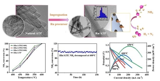
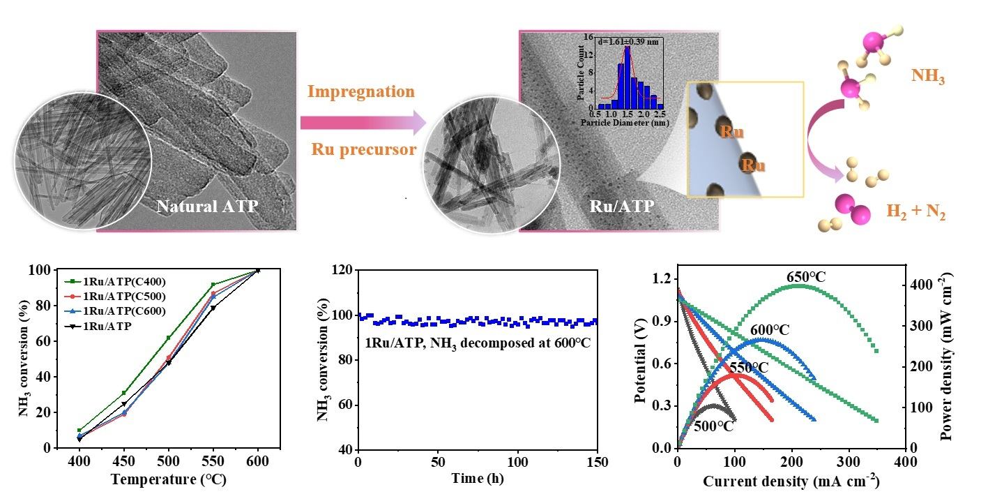
Ru/Attapulgite as an Efficient and Low-Cost Ammonia Decomposition Catalyst

1
School of Materials Science and Engineering, Shanghai University, Shanghai 200444, China
2
Key Laboratory of Advanced Fuel Cells and Electrolyzers Technology of Zhejiang Province, Ningbo Institute of Materials Technology and Engineering, Chinese Academy of Sciences, Ningbo 315201, China
3
College of Materials Science and Engineering, Hubei University of Automotive Technology, Shiyan 442002, China
*
Authors to whom correspondence should be addressed.
Submission received: 6 February 2024 / Revised: 11 March 2024 / Accepted: 13 March 2024 / Published: 16 March 2024

Abstract

:
On-site hydrogen generation from ammonia decomposition is a promising technology to address the challenges of direct transportation and storage of hydrogen. The main problems with the existing support materials for ammonia decomposition catalysts are their high cost and time-consuming preparation process. In this work, ammonia decomposition catalysts consisting of in situ-formed nano-Ru particles supported on a naturally abundant mineral fiber, attapulgite (ATP), were proposed and studied. Also, 1 wt.% Ru was uniformly dispersed and anchored onto the surface of ATP fibers via the chemical method. We found that the calcination temperatures of the ATP support before the deposition of Ru resulted in little difference in catalytic performance, while the calcination temperatures of the 1Ru/ATP precursor were found to significantly influence the catalytic performance. The prepared 1 wt.% Ru/ATP catalyst (1Ru/ATP) without calcination achieved an ammonia conversion efficiency of 51% at 500 °C and nearly 100% at 600 °C, with the flow rate of NH3 being 10 sccm (standard cubic centimeter per minute). A 150 h continuous test at 600 °C showed that the 1Ru/ATP catalyst exhibited good stability with a degradation rate of about 0.01% h−1. The 1Ru/ATP catalyst was integrated with proton ceramic fuel cells (PCFCs). We reported that PCFCs at 650 °C offered 433 mW cm−2 under H2 fuel and 398 mW cm−2 under cracked NH3 fuel. The overall results suggest low-level Ru-loaded ATP could be an attractive, low-cost, and efficient ammonia decomposition catalyst for hydrogen production.

Graphical Abstract

1. Introduction

Hydrogen has been considered a critical enabler for a sustainable energy and net zero carbon emission economy in the future. However, the problems associated with its storage and transportation have driven the researchers to explore new hydrogen carriers and hydrogen storage materials [1]. In the past decade or so, ammonia has emerged as a green energy carrier due to zero-carbon emissions upon decomposition and on-site utilization [2,3]. The most important merit of ammonia is that it can be liquified at mild conditions (at ambient temperature under about 10 atm or at −33 °C under atmospheric pressure), which makes its storage and transportation much easier than that of hydrogen [3,4,5]. Additionally, in terms of explosibility, ammonia is safer than hydrogen owing to its narrower flammability range [6]. Because of these advantages, NH3 has been considered an excellent fuel in fuel cell applications. While in general, high-temperature ceramic fuel cells such as solid oxide fuel cells (SOFCs) may tolerate NH3 gas without severe degradation, medium-temperature fuel cells that rely greatly on precious metals, such as proton ceramic fuel cells (PCFCs), typically require complete decomposition of NH3 to H2 and N2 [7]. Therefore, seeking an efficient cracking catalyst for NH3 application in low-temperature fuel cells is very critical.
Many metals and alloys have been examined as active components for ammonia decomposition catalysts, such as Ru [8], Fe [9], Ni [10], Ir [11], Co [12,13], Ru-Ni [14,15], Ru-Fe [16], Ni-Co [17], Fe-Co [18], Co-Mo [19], and Fe-Ni [20]. Among these single metal catalysts, Ru shows the highest activity towards ammonia decomposition [2,21]. Support materials, such as oxides, carbides, nitrides, and carbon nanotubes, have profound effects on Ru species via structural or electric promotion [22,23,24,25]. While carbides, nitrides, or inorganic electride-based Ru catalysts have shown relatively good catalytic activities [26,27,28,29,30], they may be either difficult to prepare or sensitive to atmosphere exposure, so the cost of preparing such support materials remains relatively high. For example, Hayashi reported excellent NH3 cracking activity using the Ru/C12A7:e catalyst; the preparation of C12A7:e is relatively complicated and requires atmosphere control [31]. Single-phase metal oxides such as Al2O3 [32], SiO2 [33], MgO [34], CaO [35], TiO2 [34] and ZrO2 [36] have also been frequently used as ammonia cracking catalyst supports; however, even with Ru decoration, these single-phase metal oxide-supported catalysts typically yield low conversion efficiencies [34]. Binary or ternary oxides have thus been developed to promote decomposition efficiency. Tan et al. demonstrated high NH3 decomposition efficiency at temperatures above 500 °C using a 2 wt.% Ru/MgO-Al2O3 catalyst [37]. Karakaya et al. [23] developed a ternary ceramic oxide compound (BaO)2(CaO)(Al2O3), which achieved a cracking efficiency of 100% above 500 °C after the impregnation of 1 wt.% Ru [7].
The above studies suggest that coupling a few oxides could be beneficial for NH3 decomposition due to a possible synergetic catalytic effect. There are many minerals in nature that have a nominal chemical formula with multiple metal elements forming complex structures, such as mica and saponite. If such natural minerals could be used as catalyst support, the preparation of NH3 decomposition catalysts could be greatly simplified, and the cost could be more friendly for industrial applications. Attapulgite (ATP), which is also known as palygorskite or Fuller’s earth [38,39,40,41], belongs to the family of phyllosilicates and is an interesting candidate mineral material. Both the names, attapulgite and palygorskite, are closely associate with their initial deposit localities, which are, respectively, the U.S. town of Attapulgus and Palygorskaya on the Popovka River in Russia. The name Fuller’s earth is best known due to its absorbent properties in products sold as absorbents or filters. ATP has also been used for decades to treat diarrhea in several antidiarrheal medications, including Diar-Aid, Diarrest, Diasorb, etc., due to its capability to physically bind to acids and toxic substances in the stomach and the digestive tract, such as adsorbing the diarrheal pathogen. These applications imply that ATP could be a good candidate for absorption of a nanosized metal catalyst.
ATP is an intermediate between di- and trioctahedral phyllosilicates, with the theoretical formula being Mg5Si8O20(OH)2(OH2)4·4H2O per half unit cell proposed by Bradley [42,43,44]. It has a layer structure constructed of double Si-O-Si tetrahedra continuous silicate chains and Mg-(O, OH) octahedra strips forming 2:1 phyllosilicate modules. There are three types of water in the formula, including four as coordinated water (OH2), four as zeolitic water (H2O), and two as hydroxyl groups (OH) [45] (see crystal structure information in later discussion). However, this is the ideal formula. Isomorphic substitution occurs easily within the ATP structure [42]. For example, Al3+ replaces Si4+ in the tetrahedral and Al3+ and Fe3+ substitutes for Mg2+ in the octahedral [46]. Hence, Si8O20Al2Mg2(OH)2(OH2)4·4H2O and (Mg5−y−z R y 3 + z)(Si8−x R x 3 + )O20(OH)2(OH2)4 R x y + 2 z / 2 2 + (H2O)4, where R2+ = Mg2+, R3+ = Al3+ or Fe3+, and □ = vacancy, were proposed to revise the formula of ATP [46,47]. Galan and Carretero suggested that the octahedral sheet contains mainly Mg, Al and Fe with R2+/R3+ close to one, and four of the five structural positions are occupied [44]. And they stated that the theoretical formula of ATP is close to (Mg2 R 2 3 + 1)(Si8−xAlx)O20(OH)2(OH2)4 R x / 2 2 + (H2O)4, where x = 0–0.5 [44]. In reality, the formulas of ATP are even more complicated and variable due to the presence of Ti4+, Na+, K+ and Ca2+ [42], such as Na0.01K0.05Ba0.01Sr0.04(Mg1.96Al1.94Fe0.03Ti0.01)(Si7.97Al0.02Fe0.01)O20(OH)2·8H2O deduced by Ogorodova et al. [48] and (Mg1.95Al1.29Fe0.58Ti0.03)(Si7.5Al0.5Fe0.01)Ca0.08K0.21Na0.49O20(OH)2(OH2)4·4H2O reported byHuang et al. [49].
Additionally, many studies have suggested that there are channels of 3.7 × 6.4 Å stretching along the c-axis of this type of fiber [50]. Such naturally created channels may provide additional benefits as catalyst support due to the probably better dispersion and deposition of metal catalyst atoms or clusters. In fact, it has already been used as support for various nanoparticles catalyzing the C-C coupling reactions [51], the glycerol steam reforming reaction [40,52,53,54], the CO oxidation reaction [55], and the methanol steam reforming reaction [56,57]. These properties and applications clearly suggest that ATP has a superior surface-absorbing capability compared with other minerals, making it very attractive as a potential catalyst support for ammonia decomposition. In addition, the advantages of using ATP as support include its easy availability and lower cost.
In this context, we designed a Ru/ATP composite catalyst for ammonia decomposition. We found that the calcination temperatures of the ATP support before the deposition of Ru result in little difference in catalytic performance, while the calcination temperatures of the 1Ru/ATP precursor are found to significantly influence the catalytic performance. HRTEM (high-resolution transmission electron microscopy) images show that Ru nanoparticles are favorably anchored on the surface of ATP with an average particle size estimated to be about 2 nm. The prepared 1Ru/ATP catalyst achieves ammonia conversion efficiencies of 51% at 500 °C and 100% at 600 °C. The catalyst exhibits excellent stability over the course of a 150 h ammonia decomposition test.
Coupled with the 1Ru/ATP catalyst, our PCFCs achieve 433 mW cm−2 under H2 fuel and 398 mW cm−2 under cracked NH3 fuel at 650 °C. Although Ru is a precious metal, its loading content is relatively low, and there is a possibility to further decrease its content by alloying Ru with other non-precious metals or applying a core–shell structure design [16,58]. In addition, ATP is relatively inexpensive compared with many synthetic support materials. Therefore, 1Ru/ATP could be a promising catalyst for on-site hydrogen production via ammonia decomposition.

2. Results and Discussion

2.1. Crystal Structure and Elementary Composition Analysis of ATP

In terms of crystal structure in ATP, there exist debates in the literature. Bradley showed ATP has a monoclinic structure with the space group of C2/m [43]. Christ et al. concluded that ATP exists in structurally related orthorhombic and monoclinic forms [59]. Chisholm suggested that most ATP samples are mixtures of monoclinic and orthorhombic polymorphs [45,60]. However, regardless of either monoclinic or orthorhombic polymorph, they both have similar lattice parameters in a, b and c, except the β angle is slightly greater than 90o in the monoclinic form. In addition, as mentioned in the Introduction, both polymorphs are constructed of double Si-O-Si tetrahedra continuous silicate chains and Mg-(O, OH) octahedra discontinuous strips as shown in Figure 1a. Note that commonly, the octahedra layer has only four of the five sites occupied [45,46]. The three types of water, i.e., coordinated or crystallographically bound water (OH2), zeolitic water (H2O), and hydroxyl groups (OH), are also marked in Figure 1a. At relatively low temperatures when the water molecules are not released out of the structure, ATP forms nice water molecule-filled channels parallel to the c axis as shown in Figure 1b. At higher temperatures such as at 887 °C after complete water removal, Post and Heaney observed transition from parallel double tetrahedra and octahedra chains to folded chain structure as in shown Figure 1c with a reduced cross-sectional area of the channels [45].
Based on the XRD analysis of the as-received natural ATP powder (Figure 1d), we confirmed that our ATP mostly consists of an orthorhombic form, with a slightly expanded a, b values and a reduced c value compared with the reference data as shown in Table 1. The three values are also close to the monoclinic form deduced by Post and Heaney [45].
Since the powder is expected to be used at around 400–600 °C, XRD patterns of calcined ATP are also shown in Figure 1d. As presented in Figure 1d, the peaks are broad, indicating that the crystallites are relatively small. The average particle size is around 1 µm. The main peaks that appeared at 2θ = 13.7°, 16.3°, 19.8°, 24.2°, 27.5°, and 35.2° were well-indexed as those of Mg5(Si,Al)8O20(OH)2·8H2O [61]. The characteristic peaks of calcined ATP became less intense and even broader as the calcination temperature increased. We noticed there were a couple newly formed peaks which could be described by either monoclinic or orthorhombic structure in the XRD database. It is possible that these newly formed peaks might have reflected the deformation and folding of the open channels due to the loss of water during heat treatment. However, we were unable to find a reference pdf card that provides peak information for a calcined ATP; we marked those peaks as unknown high-temperature (HT) peaks. Overall, it seems the crystal structure of ATP was not greatly altered after calcination.
The composition of ATP was quantitatively analyzed by ICP-OES, and the number of atoms corresponding to general structural formula, Mg5Si8O20(OH)2(OH2)4·4H2O, are given in Table 2. Our natural ATP is rich in Si, Mg, and Al elements. The tetrahedral substitution in the natural ATP is very low (0.03). This is consistent with the results of several samples reported by Suárez et al. [62]. Although Fe is present in the sample, the ratio of R2+ to R3+ is 1.32; the Al content is less than the Mg content in the octahedral layer. The analysis showed that 3.96 of 5 octahedral sites were occupied [49]. The formula of our ATP sample calculated based on 42 charges has the form of (Mg2.23Al1.24Fe0.45Ti0.03Mn0.01)(Si7.97Al0.03)Ca0.10K0.12Na0.01O20(OH)2(OH2)4·4H2O, which agrees with those reported in other studies [44,63].

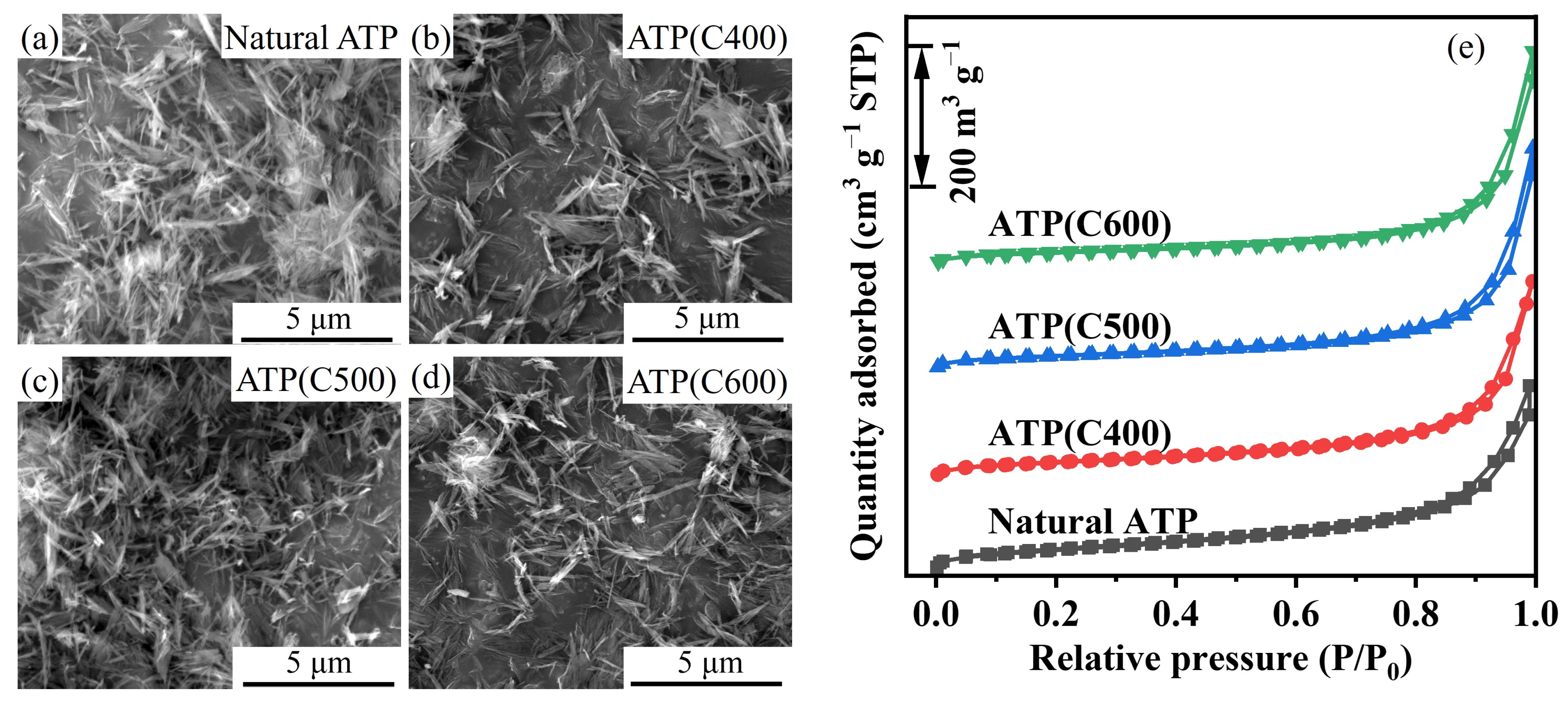
2.2. Thermal Stability and Morphology of Natural ATP

The thermal stability of the ATP used as the catalytic support is studied before the deposition of Ru. The thermal stability of the natural ATP without heat treatment is further investigated using TG-DSC analysis (see Figure 2). ATP has not only different types of water which exist in the crystal structure as previously discussed, but also different types of adsorption water due to exposure to environment [64]. A slight endothermic peak is observed at around 92 °C on the DSC curve, which corresponds to a weight loss of about 10 wt.% on the TG curve. This dehydration step is attributed to the desorption of the adsorbed water and pore water [64]. The endothermic peak, which appears at about 214 °C, with a weight loss of about 4 wt.%, is responsible for the removal of crystallographically bound water [64]. An obvious weight loss of about 5 wt.% and a slight mass change of about 1 wt.% are also observed, although no corresponding peaks are identified on the DSC curve, which results from the possible release of residual crystal water and structural water, respectively [64].
Figure 3 shows the morphologies and N2 adsorption–desorption isotherms of ATP before and after calcination. As demonstrated in Figure 3a, ATP before calcination presents a fiber-like structure, and the stacking of elongated rods into bundles generates slit-like pores and voids with different sizes [65]. The morphologies of ATP(C400), ATP(C500), and ATP(C600) are displayed in Figure 3b–d. The calcined samples exhibit no obvious changes, which is in good agreement with the XRD results. Figure 3e shows the N2 adsorption–desorption isotherms of ATP and the calcined samples, and the properties of these samples are summarized in Table 3. Hysteresis appeared at higher relative pressures (0.8 < P/P0 < 1) for all samples, indicating the presence of interparticle mesopores [55]. The specific surface area was 134.2 m2 g−1 for natural ATP and decreased to 87.2 m2 g−1 for calcined ATP at 600 °C. The pore diameter showed an opposite trend. The pore volume increased followed by a decline when the calcination temperature reached 600 °C. The results are consistent with those reported in the work of Mo et al. [66]. The dehydration of ATP under mild calcination temperature (e.g., 400 °C) should increase the accessibility of molecules into the inner pores; however, it is difficult for the adsorbate (N2, nonpolar) to diffuse into the micropores [66]. Further increasing the calcination temperature to 600 °C lead to the collapse of crystal structure and aggregation of the fibers to form larger pores [61,66].

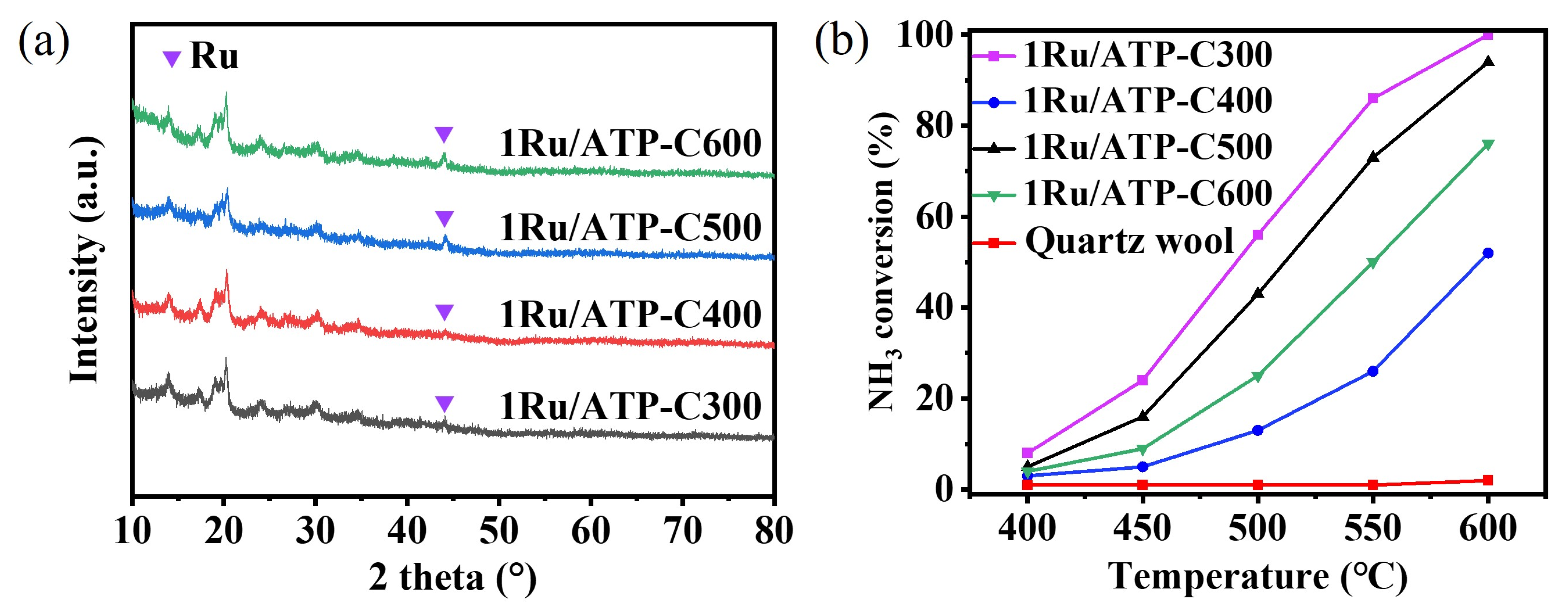
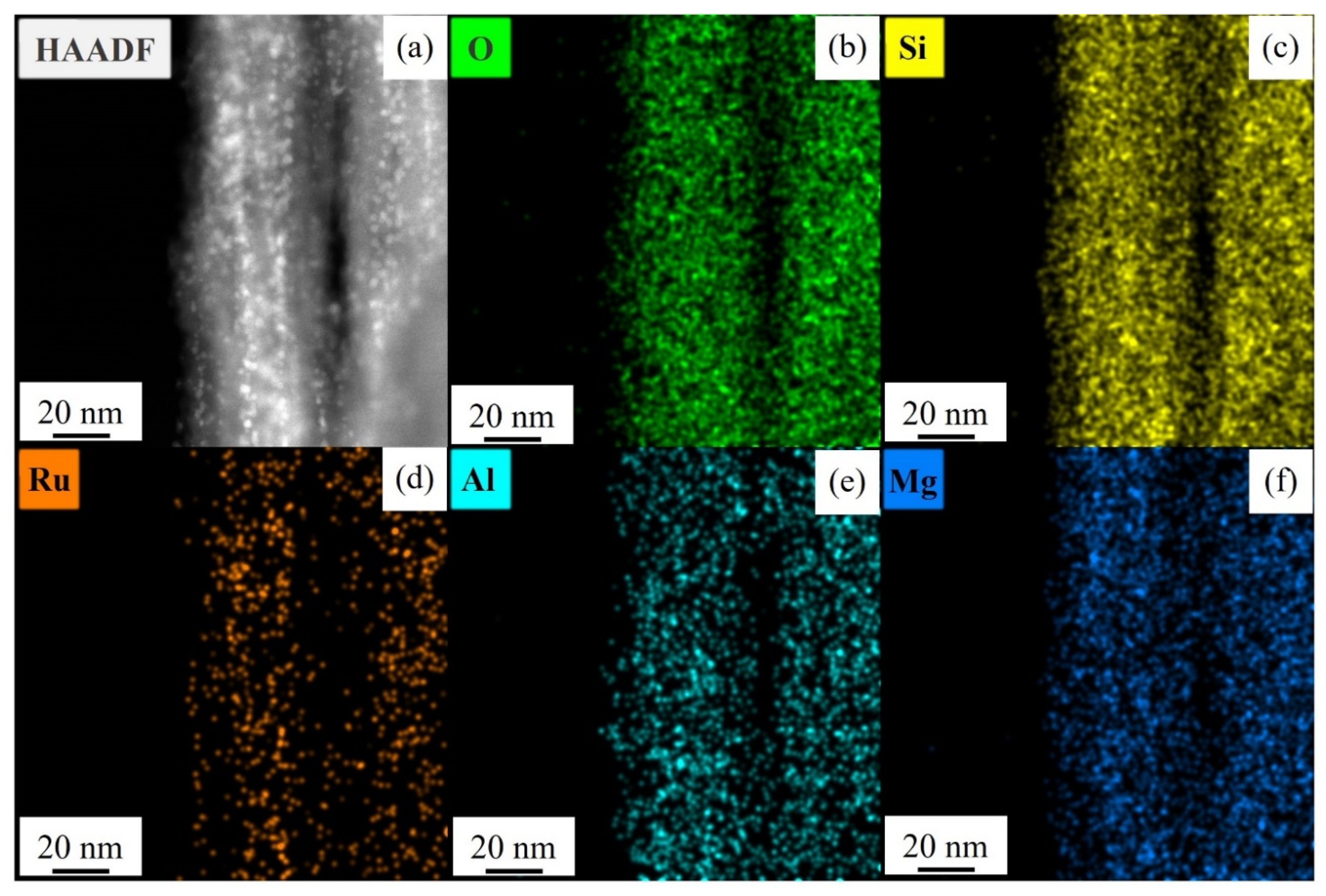
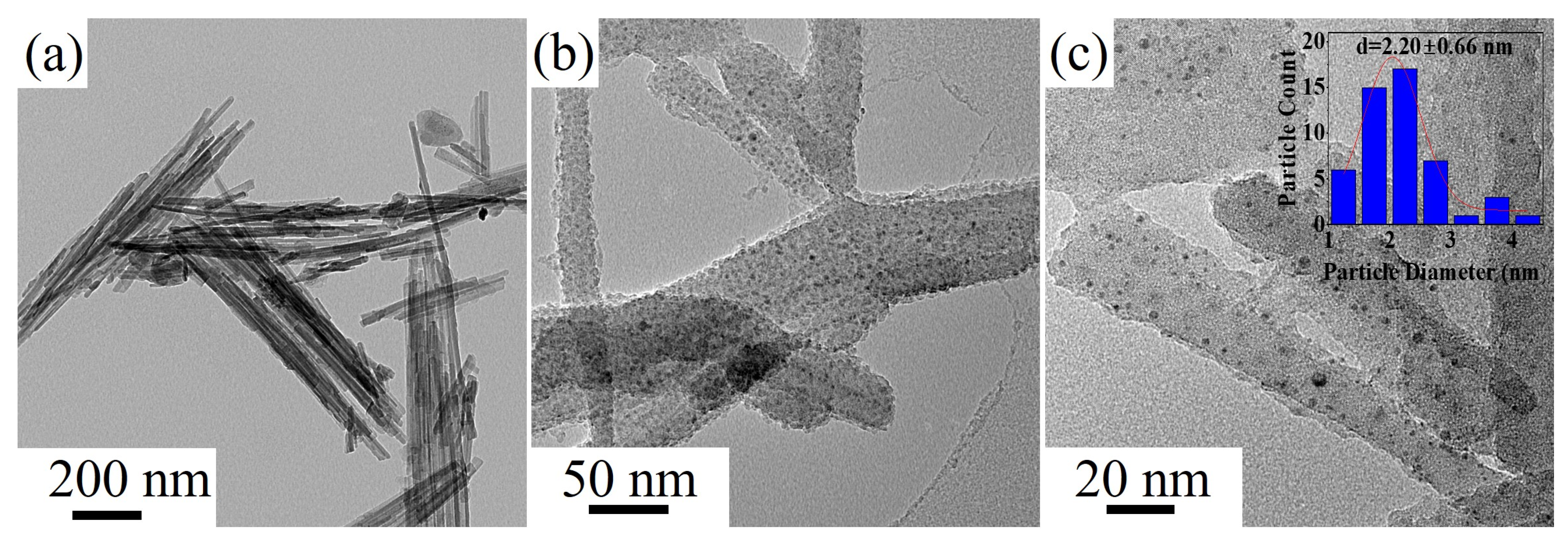
2.3. Characterization and Evaluation of the Ru-ATP Catalyst

In order to study the effect of calcination temperatures on catalytic performance, we heat-treated the 1Ru/ATP precursor and ATP support at different temperatures to prepare two series of catalysts, namely the calcined-1Ru/ATP series and the calcined-ATP series.
The 1Ru/ATP precursor was calcined at 300 °C, 400 °C, 500 °C and 600 °C and then reduced in situ at 600 °C. The obtained catalysts were denoted as 1Ru/ATP-C300, 1Ru/ATP-C400, 1Ru/ATP-C500 and 1Ru/ATP-C600, respectively. Figure 4a presents the XRD profiles of the calcined 1Ru/ATP precursor. The diffraction peaks of ATP in the calcined catalysts are broader and less intense in comparison to natural ATP in Figure 1d, which has been reported in other works [64]. Cao et al. [55] indicated that, in the CuO/ATP catalyst system, the decreased diffraction intensities of CuO/ATP catalysts might originate from the fine dispersion of CuO particles on the surface of ATP clay and the strong interaction between CuO and ATP support. Wang et al. [61] suggested that nickel oxide species in calcined Ni/ATP catalysts may interact with ATP to form Ni(Si, Mg, Al)-O species. In the present study, we believe that the Ru particles are highly dispersed on the surface of ATP or interact with the ATP framework, which leads to the decreased diffraction peak intensity of the calcined catalysts. In addition, the heat treatment of ATP in these catalysts also makes the peaks broader and less intense. We also observe that, as the calcination temperature increases, the intensity of the peak at 2θ = 44.0° attributed to Ru increases. This might be due to the sintering of Ru particles at higher temperatures.
The catalytic performance of the calcined 1Ru/ATP precursor is shown in Figure 4b. 1Ru/ATP-C300 shows the highest NH3 conversion over the entire temperature range, with the NH3 conversion varying from 8% at 400 °C to 100% at 600 °C. The NH3 conversion decreases as the calcination temperature increases from 300 °C to 600 °C, which is ascribed to the agglomeration of particles at higher calcination temperatures. It should be noted that 1Ru/ATP-C400 exhibits the lowest catalytic performance. As also indicated in Figure 4b, the catalytic activity of the quartz wool is negligible since the NH3 conversion is less than 2% between 400 and 600 °C.
We noticed that during the heat treatment, the ATP support experiences weight loss demonstrated in Figure 2 and changes in textual properties listed in Table 3. Considering this, we calcined the ATP support at 400, 500 and 600 °C, and the calcined samples were then used as support to prepare 1Ru/ATP(C400), 1Ru/ATP(C500) and 1Ru/ATP(C600), respectively. After the Ru precursor was impregnated onto the supports, the catalysts were reduced in situ at 300 °C. The natural ATP without calcination was also used to prepare 1Ru/ATP following the same steps. The XRD results of 1Ru/ATP(C400), 1Ru/ATP(C500), 1Ru/ATP(C600) and 1Ru/ATP are given in Figure 5a. We observed that the intensities of the characteristic peaks of ATP are closely related to the calcination temperatures, as is revealed by the XRD results of calcined ATP in Figure 1. No obvious peaks can be attributed to Ru for this series of catalysts, which is due to the higher dispersion and low content of Ru [30].
The obtained ammonia conversion over these catalysts is plotted in Figure 5b. The ammonia conversion over 1Ru/ATP(C600) and 1Ru/ATP(C500) are similar. This series of catalysts yielded very similar NH3 conversions, with the 1Ru/ATP(C400) catalyst offering relatively higher catalytic performance at lower 600 °C. For the 1Ru/ATP catalyst, where the ATP was not calcined before the deposition of Ru, NH3 conversions of 51% at 500 °C and about 100% at 600 °C were realized.
The above results show that the calcination temperatures of ATP support before the deposition of Ru resulted in little difference in catalytic performance, while the calcination temperatures of 1Ru/ATP precursor were found to significantly influence the catalytic performance. On one hand, calcination of ATP only influenced the support. Though the support suffered from a slight weight loss upon heating, the crystal structure of the support was not greatly altered after calcination, as revealed by the XRD results. And it seems that a moderate decline in the surface area did not affect the activity, which can also be found with other support materials, such as SiO2 [33]. On the other hand, we believe that calcination of 1Ru/ATP precursors at higher temperatures leads to the agglomeration of Ru species. Therefore, less crystal facets with greater catalytic activity were exposed.
We understand that the morphology of a catalyst plays an important role in its catalytic activity. The prepared and tested catalysts were thus analyzed using SEM and TEM. As shown in Figure 6a,b, natural ATP without calcination is highly porous, with a diameter of about 40 nm and a length of about 1–2 μm. Compared with natural ATP, the 1Ru/ATP catalyst after reduction shows no observable changes, as shown in Figure 6d,e. Furthermore, the Ru particles are not identifiable due to their small particle sizes under the SEM mode, as shown in Figure 6c,f, consistent with the XRD results.
Figure 7 reveals the TEM images of the natural ATP and the 1Ru/ATP catalysts. Figure 7a,b offers the overall view of ATP, which is highly fibrous. The surface of the ATP is rough, which is beneficial for enlarging the specific surface area of the ATP (see Figure 7c,d). Yin et al. [67] claimed that high surface area could result in good dispersion of Ru species and thus high catalytic activity. The preparation process did not change the fiber-like structure of the ATP in Figure 7e, which agrees with the results of SEM analysis. As demonstrated in Figure 7f–h, numerous fine particles in the 1Ru/ATP catalyst are anchored favorably onto the surface of the ATP fibers. The particle size distribution is shown in the inset of Figure 7g. The average size of these particles is estimated to be about 2 nm according to Equation (1). A few particles shown in the HRTEM images had observable lattice fringes (see Figure 7i–k,m–o). Crystal facets (101) and (002) of Ru nanoparticles were identified. The lattice spacing of 2.05 Å corresponds to the (101) facet, and similarly, the lattice spacing of 2.13 Å and 2.14 Å is related to the (002) facet. The selected electronic diffraction patterns (Figure 7l,p) obtained by applying the Fast Fourier transform to the HRTEM images indicate that the Ru species are in the form of single crystals.
The HAADF-STEM (see Figure 8a) and the corresponding EDS mapping spectra (see Figure 8b–f) of the 1Ru/ATP catalyst after reduction are shown in Figure 8. The EDS mapping with different color spots demonstrates that the studied sample is rich in O, Si, Al, and Mg elements. These elements have a homogeneous distribution. This confirms the existence of crystalline Mg5(Si,Al)8O20(OH)2·8H2O within the ATP, which is in good agreement with the XRD profiles in Figure 1d. The distribution of Ru is the least highlighted due to its content being the lowest.
The catalytic activity of the 1Ru/ATP catalyst in this work is compared to that described in the literature, as demonstrated in Table 4. The ammonia conversion efficiency of the 1Ru/ATP catalyst in this study is superior to those of catalysts with AC [68], ZrO2 [36] as supports and even comparable to that of the cases using CNTs as support [69]. Although the catalytic activity of 1Ru/ATP is lower than that of some other Ru-based catalysts listed in Table 4, most of these catalysts were loaded with higher Ru content or operated at lower flow rate. It is well known that support materials affect the activity of catalysts by resulting in differences in the dispersion, size and electronic structure of Ru nanoparticles [70]. In our study, the average size of Ru nanoparticles is about 2 nm. As revealed in previous studies, Ru particles with a size of about 2 nm achieved the best NH3 conversion owing to an optimal amount of B5-type sites, which have been recognized as highly active for both the dissociation of N2 and the association of N [22,71]. The B5-type sites on the surface of Ru nanoparticles induce the high activity of Ru-based catalysts [72].
Figure 9 demonstrates the morphology of 1Ru/ATP after ammonia decomposition test. The fiber-like structure is retained after the test as shown in Figure 9a. We also observed that the Ru nanoparticles were evenly distributed on the ATP surface in Figure 9b,c. The inset in Figure 9c shows the distribution of the nanoparticles. We found that the size of the nanoparticles increases slightly after the test, which was also reported for other ATP-supported catalysts [52,75].
Figure 10 exhibits the ammonia conversion efficiency of 1Ru/ATP during the long-term test at 600 °C. No obvious degradation for NH3 decomposition occurs during the 150 h operation, and the degradation rate is 0.01% h−1. Regarding the good stability of 1Ru/ATP, the possible reason is due to the strong interaction between Ru and the ATP support, which is conducive to reduction in the coarsening of Ru nanoparticles. Wang et al. found that when the prepared Ni/ATP was used in the steam reforming ethanol reaction, the catalyst maintained good stability for up to 61 h, and they believed that a new species was formed between Ni and ATP, such as Ni(Mg, Al)-O and (NixMg1−x)(OH)4Si2O5, which inhibited the coarsening of Ni particles [61]. A similar conclusion was reached by Cao et al., who prepared ATP-supported CuO nanoparticles to catalyze the CO reaction, showing only slight degradation over a long period of up to 14 h [55]. Thus, ATP is a potential support material for Ru-based ammonia decomposition catalysts.
The possible mechanism of relatively high NH3 conversion efficiency in Ru-loaded ATP catalysts was investigated based on our results and previous studies. First, the activity of Ru-based catalysts is structure-sensitive [33]. Supports may affect Ru particle size and shape [70], which influences the concentration of active sites [70]. In this study, the rough surface of ATP functions as anchoring sites for Ru particles, resulting in an average particle size of about 2 nm. In addition, the structural and textual properties of ATP endow it with remarkable sorption capacity which is mainly influenced by two factors, i.e., mineral fiber surfaces and the channels that stretch along the c-axis [76]. The surface of ATP has silanol groups, surficial oxygen atoms, and structural H2O, along with broken bonds which allow for cations to interact with the ATP surface [76]. The channels possibly permit the exchange of metal cations [76]. In our study, we believe that such surface properties may be helpful for Ru harboring and nucleation. Additionally, the isomorphism effect, mentioned in Section 3.1, results in numerous crystallographic defects [77]. The negatively charged defects can be compensated by exchangeable cations [77]. We suppose that Ru3+ may be electrostatically adsorbed to the ATP surface. In summary, ATP is an efficient support material for Ru thanks to its unique surface properties and crystal structure, lower cost, and easy availability.

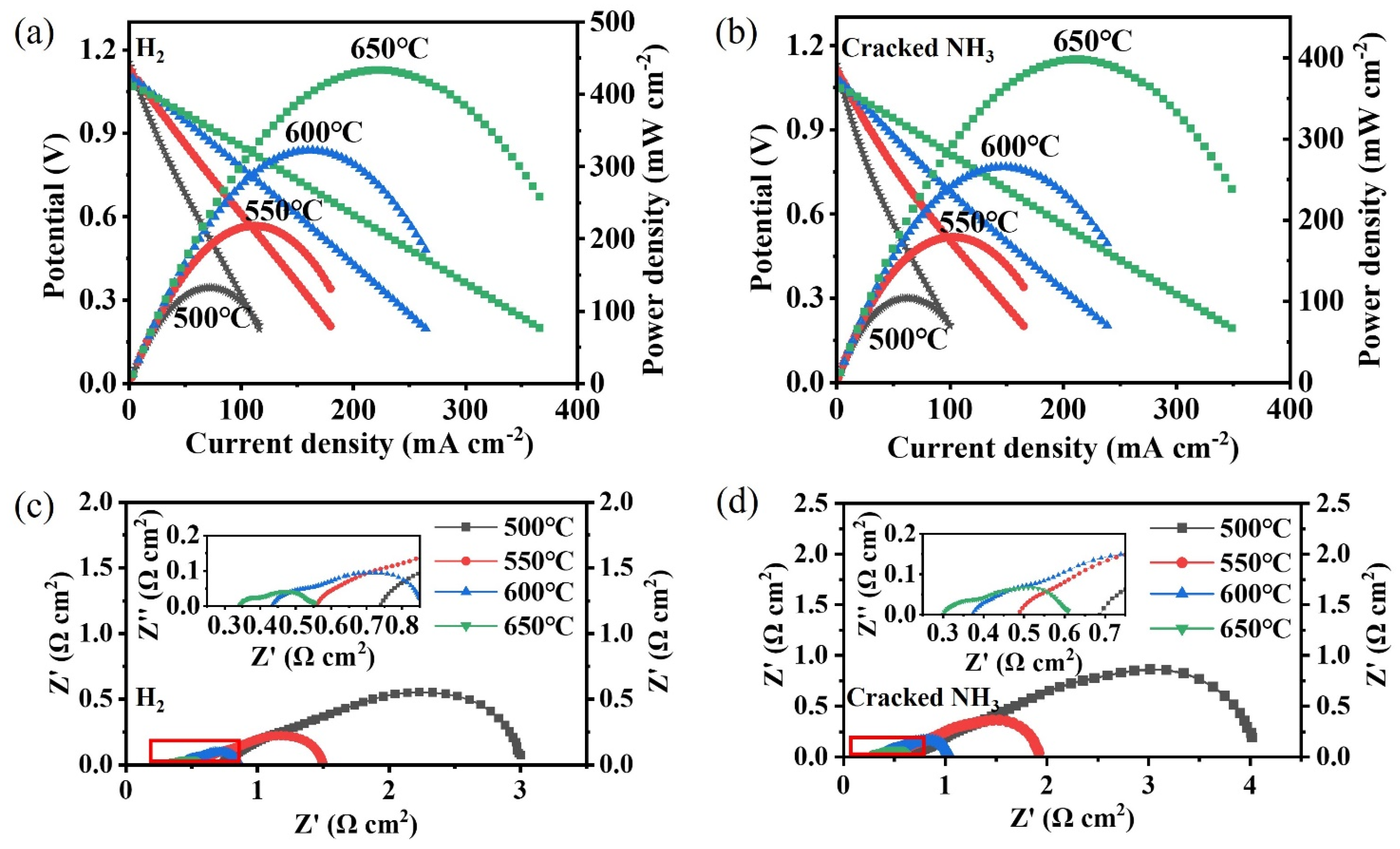
2.4. NH3-Fed Proton Ceramic Fuel Cells with 1Ru/ATP

Proton ceramic fuel cells (PCFCs), which are considered an increasingly important sub-class of solid oxide fuel cells, can directly convert chemical energy stored in H2 into electrical energy. However, Zhu et al. [7] observed a rapid drop in OCV and dramatical increase in ohmic and polarization resistance for PCFCs supplied with uncracked ammonia. This inspired us to integrate 1Ru/ATP with PCFCs.
The PCFCs were first fed with pure H2 as a baseline reference. Figure 11a demonstrates the electrochemical performance of the cells. The maximum power densities are 433, 322, 218, and 132 mW cm−2 at 650, 600, 550, and 500 °C, respectively. The fuel fed into the same cell was changed to NH3 cracked at 600 °C, and the corresponding maximum power densities were 398, 266, 179, and 104 mW cm−2 at 650, 600, 550, and 500 °C, respectively, as shown in Figure 11b. The maximum power densities in cracked NH3 were reduced by 8.1%, 17.4%, 17.9%, and 21% at 650, 600, 550, and 500 °C, respectively. The reduction in electrochemical performance is attributed to the dilution of N2 in H2 [78,79].
Electrochemical impedance spectra (EIS) of the PCFC under H2 and cracked NH3 at different temperatures are plotted in Figure 11c,d. The ohmic resistance (Ro) and polarization resistance (Rp) taken from the EIS are listed Table 5. We found that Ro under cracked NH3 was slightly lower while Rp was higher. Lower Ro is explained by the activation of the cell under H2 [80,81,82]. And higher Rp is mainly explained by the dilution effect of N2 for H2 [83]. A larger increase in Rp results in the reduction in electrochemical performance, although there is a slight reduction in Ro.

3. Materials and Methods

3.1. Preparation of the Samples

Natural ATP (Xuyi, Jiangsu Province, China) was used as the support material without further purification. Calcined ATP samples were prepared to study the thermal stability of ATP. ATP was calcined in ambient air for 2 h at 400 °C, 500 °C, and 600 °C, and the obtained samples were denoted as ATP(C400), ATP(C500), and ATP(C600), respectively.
The catalysts were prepared using the wet impregnation method, with RuCl3 (Energy Chemicals, Anhui Province, China) as the precursor of Ru and natural ATP as support. RuCl3 was dissolved in 20 mL of anhydrous ethanol. After vigorous stirring, a suspension of ATP (1 g) in anhydrous ethanol (20 mL) was added to the RuCl3 solution. Then, the mixed suspension was stirred on a hot plate set at 85 °C until a solid precursor formed and no obvious anhydrous ethanol was left. The solid precursor was then further dried in an oven at 85 °C for 24 h to completely remove the remaining volatiles, followed by grinding with a mortar. The loading of Ru was 1 wt.%, and the powder was denoted as 1Ru/ATP precursor. The 1Ru/ATP precursor was calcined in air for 2 h at different temperatures (300–600 °C). The obtained products were labelled as 1Ru/ATP-C300, 1Ru/ATP-C400, 1Ru/ATP-C500 and 1Ru/ATP-C600, respectively. In addition, another series of catalysts were prepared following the same steps as 1Ru/ATP precursor using calcined ATP samples (i.e., ATP(C400), ATP(C500), ATP(C600)) and non-calcined (natural) ATP as supports, which were recorded as 1Ru/ATP(C400), 1Ru/ATP(C500), 1Ru/ATP(C600) and 1Ru/ATP.

3.2. Characterization of the Samples

Crystalline structure measurements of the support and the catalyst were performed with an X-ray diffractometer (D8 ADVANCE DAVINCI, Karlsruhe, Germany) using Cu Ka radiation (λ = 1.5418 Å). Elemental composition of ATP was analyzed via inductively coupled plasma–optical emission spectrometry (ICP-OES) using Agilent 5110 (USA). The scanning electron microscopy images of samples were recorded using hot field scanning electron microscopy (SEM) (FEI Quanta FEG 250, Waltham, MA, USA) and cold field SEM (S4800, Tokyo, Japan). Transmission electron microscopy (TEM) images of all catalysts were obtained on JEOL2100 (JEM2100, Tokyo, Japan), TF20 (Tecnai F20, Hillsboro, OR, USA), and JEOL JEM-F200 (Tokyo, Japan). HRTEM and high-angle annular darkfield scanning TEM (HAADF-STEM) images were recorded by a HRTEM (Spectra 300, Notre Dame, IN, USA). The average size of the Ru particle (dn) was calculated according to [22]:
d n = i n i d i i n i
where ni stands for the number of particles with diameter di. At least 50 particles were measured from TEM. TG-DSC was conducted on a TGA 8000-Spectrum (PerkinElmer, USA). The sample was heated from ambient temperature to 760 °C at a rate of 10 °C/min in nitrogen. N2 adsorption–desorption isotherms were collected using a surface area and porosity analyzer (Micromeritics ASAP 2460, Norcross, GA, USA). The samples were degassed at 200 °C for 6 h before measurement. The surface area of the samples was calculated using the Brunauer–Emmette–Teller (BET) method. The pore volume and pore size were estimated from desorption isotherms applying the Barrett–Joyner–Halenda (BJH) method.

3.3. Catalytic Performance Test

The catalytic tests were conducted in a continuous-flow quartz reactor (inner diameter: 5 mm) at atmospheric pressure. The catalyst powders (0.1 g) were mechanically mixed with about 0.1 g of inert quartz wool and then packed into the center of a reaction tube, occupying a volume of ca. 0.79 cm3. Prior to the reaction, the catalysts were reduced in situ under H2 flow at 300 °C or 600 °C for 3 h and purged with pure nitrogen. The decomposition of NH3 was carried out in the temperature range of 400–600 °C under pure NH3 with a flow rate of 10 sccm (standard cubic centimeter per minute). The off gas from the reactor was introduced into an ammonia analyzer (RL-B201, Xi’an, China) to obtain the ammonia conversion efficiency.

3.4. Fabrication and Electrochemical Characterization of Fuel Cells

The fabrication and electrochemical characterization of the fuel cells can be found in our previous work [84]. Two separate reactors were used to crack NH3 and perform the fuel cell performance test. Before being supplied into the PCFCs, NH3 was cracked into N2 and H2 over 1Ru/ATP at 600 °C. The cracked gas was directly introduced to the PCFCs. During the electrochemical test, the NH3 cracking temperature was maintained at 600 °C while the temperature of PCFCs varied from 500 to 650 °C. The flow rate of H2 and NH3 was 10 sccm.

4. Conclusions

In this study, the catalytic activity of the Ru/ATP catalyst for NH3 decomposition was investigated. ATP exhibited good thermal stability and retained the fiber-like structure after calcination at 600 °C in air for 2 h. We found that the calcination temperatures of the ATP support before the deposition of Ru resulted in little difference in catalytic performance, while the calcination temperatures of the 1Ru/ATP precursor had a significant effect on catalytic performance. Owing to the high surface area reaching 134 m2 g−1 in the as-received powder and the rough surface of ATP support, Ru nanoparticles were homogeneously and firmly anchored on the surface of ATP, with an average particle size of 2 nm. Ammonia cracking efficiencies of 51% and 100% were achieved on the 1Ru/ATP catalyst at 500 °C and 600 °C, respectively. The ammonia cracking efficiency was stable during the 150 h long-term test, presenting the excellent stability of the 1Ru/ATP catalyst. Coupled with the 1Ru/ATP catalyst and tested at 650 °C, our PCFCs achieved a peak power density of 433 mW cm−2 under H2 fuel and 398 mW cm−2 under cracked NH3. Furthermore, as ATP is inexpensive, it could be used as a support for other catalysts, such as bimetallic catalysts or core–shell-structured Ru-non-precious metals with reduced content of Ru. Related work is undergoing.

Author Contributions

Conceptualization, L.Z.; Methodology, Q.T., H.T. and L.Z.; Software, H.T.; Validation, Q.T.; Formal analysis, J.S., Y.W., H.L., W.G., C.D., F.L. and L.Z.; Investigation, G.C.; Resources, W.G.; Data curation, G.C.; Writing—original draft, Q.T.; Writing—review and editing, J.S. and L.Z.; Supervision, C.D. and L.Z.; Funding acquisition, L.Z. All authors have read and agreed to the published version of the manuscript.

Funding

The work was supported by the Ningbo Municipal People’s Government (Grant No. 2021A-162-G, Grant No. 2022Z027, Grant No. 2023Z103), National Key R&D Program of China (No. 2022YFB4002203), and Chinese Academy of Science.

Data Availability Statement

The data presented in this study are available.

Conflicts of Interest

The authors declare no conflicts of interest.

References

  1. Li, R.; Kawanami, H. A Recent Review of Primary Hydrogen Carriers, Hydrogen Production Methods, and Applications. Catalysts 2023, 13, 562. [Google Scholar] [CrossRef]
  2. Afif, A.; Radenahmad, N.; Cheok, Q.; Shams, S.; Kim, J.H.; Azad, A.K. Ammonia-fed fuel cells: A comprehensive review. Renew. Sustain. Energy Rev. 2016, 60, 822–835. [Google Scholar] [CrossRef]
  3. Sun, S.C.; Jiang, Q.Q.; Zhao, D.Y.; Cao, T.T.; Sha, H.; Zhang, C.K.; Song, H.T.; Da, Z. Ammonia as hydrogen carrier: Advances in ammonia decomposition catalysts for promising hydrogen production. Renew. Sustain. Energy Rev. 2022, 169, 112918. [Google Scholar] [CrossRef]
  4. Wang, B.; Li, T.; Gong, F.; Othman, M.H.D.; Xiao, R. Ammonia as a green energy carrier: Electrochemical synthesis and direct ammonia fuel cell-a comprehensive review. Fuel Process. Technol. 2022, 235, 107380. [Google Scholar] [CrossRef]
  5. Yi, Y.; Chen, J.; Xu, M.; Yang, G.; Ran, R.; Zhou, W.; Wang, W.; Shao, Z. Exsolved Nanoparticles Decorated Double Perovskites as High-Performance Anodes for Direct-Ammonia Solid Oxide Fuel Cells. Catalysts 2023, 13, 996. [Google Scholar] [CrossRef]
  6. El-Shafie, M.; Kambara, S. Recent advances in ammonia synthesis technologies: Toward future zero carbon emissions. Int. J. Hydrogen Energy 2023, 48, 11237–11273. [Google Scholar] [CrossRef]
  7. Zhu, L.Z.; Cadigan, C.; Duan, C.C.; Huang, J.K.; Bian, L.Z.; Le, L.; Hernandez, C.H.; Avance, V.; O’Hayre, R.; Sullivan, N.P. Ammonia-fed reversible protonic ceramic fuel cells with Ru-based catalyst. Commun. Chem. 2021, 4, 121. [Google Scholar] [CrossRef] [PubMed]
  8. Borisov, V.A.; Iost, K.N.; Temerev, V.L.; Simunin, M.M.; Leont’eva, N.N.; Mikhlin, Y.L.; Volochaev, M.N.; Shlyapin, D.A. Ammonia decomposition Ru catalysts supported on alumina nanofibers for hydrogen generation. Mater. Lett. 2022, 306, 130842. [Google Scholar] [CrossRef]
  9. Duan, X.Z.; Qian, G.; Zhou, X.G.; Sui, Z.J.; Chen, D.; Yuan, W.K. Tuning the size and shape of Fe nanoparticles on carbon nanofibers for catalytic ammonia decomposition. Appl. Catal. B-Environ. 2011, 101, 189–196. [Google Scholar] [CrossRef]
  10. Atsumi, R.; Noda, R.; Takagi, H.; Vecchione, L.; Di Carlo, A.; Del Prete, Z.; Kuramoto, K. Ammonia decomposition activity over Ni/SiO2 catalysts with different pore diameters. Int. J. Hydrogen Energy 2014, 39, 13954–13961. [Google Scholar] [CrossRef]
  11. Papapolymerou, G.; Bontozoglou, V. Decomposition of NH3 on Pd and Ir—Comparison with Pt and Rh. J. Mol. Catal. A-Chem. 1997, 120, 165–171. [Google Scholar] [CrossRef]
  12. Yakovenko, R.E.; Krasnyakova, T.V.; Saliev, A.N.; Shilov, M.A.; Volik, A.V.; Savost’yanov, A.P.; Mitchenko, S.A. Ammonia Decomposition over Cobalt-Based Silica-Supported Fischer-Tropsch Synthesis Catalysts. Kinet. Catal. 2023, 64, 180–190. [Google Scholar] [CrossRef]
  13. Wang, L.; Yi, Y.; Guo, H.; Du, X.; Zhu, B.; Zhu, Y. Highly Dispersed Co Nanoparticles Prepared by an Improved Method for Plasma-Driven NH3 Decomposition to Produce H2. Catalysts 2019, 9, 107. [Google Scholar] [CrossRef]
  14. Lucentini, I.; Colli, G.G.; Luzi, C.D.; Serrano, I.; Martínez, O.M.; Llorca, J. Catalytic ammonia decomposition over Ni-Ru supported on CeO2 for hydrogen production: Effect of metal loading and kinetic analysis. Appl. Catal. B-Environ. 2021, 286, 119896. [Google Scholar] [CrossRef]
  15. Lucentini, I.; Casanovas, A.; Llorca, J. Catalytic ammonia decomposition for hydrogen production on Ni, Ru and Ni-Ru supported on CeO2. Int. J. Hydrogen Energy 2019, 44, 12693–12707. [Google Scholar] [CrossRef]
  16. Chen, C.; Chen, Y.W.; Ali, A.M.; Luo, W.J.; Wen, J.; Zhang, L.H.; Zhang, H. Bimetallic Ru-Fe Nanoparticles Supported on Carbon Nanotubes for Ammonia Decomposition and Synthesis. Chem. Eng. Technol. 2020, 43, 719–730. [Google Scholar] [CrossRef]
  17. Wu, Z.W.; Li, X.; Qin, Y.H.; Deng, L.D.; Wang, C.W.; Jiang, X.M. Ammonia decomposition over SiO2-supported Ni-Co bimetallic catalyst for COx-free hydrogen generation. Int. J. Hydrogen Energy 2020, 45, 15263–15269. [Google Scholar] [CrossRef]
  18. Zhang, J.; Müller, J.O.; Zheng, W.Q.; Wang, D.; Su, D.S.; Schlögl, R. Individual Fe-Co alloy nanoparticles on carbon nanotubes: Structural and catalytic properties. Nano Lett. 2008, 8, 2738–2743. [Google Scholar] [CrossRef]
  19. Duan, X.Z.; Ji, J.; Yan, X.D.; Qian, G.; Chen, D.; Zhou, X.G. Understanding Co-Mo Catalyzed Ammonia Decomposition: Influence of Calcination Atmosphere and Identification of Active Phase. Chemcatchem 2016, 8, 938–945. [Google Scholar] [CrossRef]
  20. Yi, Y.H.; Wang, L.; Guo, Y.J.; Sun, S.Q.; Guo, H.C. Plasma-assisted ammonia decomposition over Fe-Ni alloy catalysts for COx-Free hydrogen. Aiche J. 2019, 65, 691–701. [Google Scholar] [CrossRef]
  21. Yin, S.F.; Xu, B.Q.; Zhou, X.P.; Au, C.T. A mini-review on ammonia decomposition catalysts for on-site generation of hydrogen for fuel cell applications. Appl. Catal. A-Gen. 2004, 277, 1–9. [Google Scholar] [CrossRef]
  22. Duan, X.Z.; Zhou, J.H.; Qian, G.; Li, P.; Zhou, X.G.; Chen, D. Carbon Nanofiber-Supported Ru Catalysts for Hydrogen Evolution by Ammonia Decomposition. Chin. J. Catal. 2010, 31, 979–986. [Google Scholar] [CrossRef]
  23. Karakaya, C.; Huang, J.; Cadigan, C.; Welch, A.; Kintner, J.; Beach, J.; Zhu, H.Y.; O’Hayre, R.; Kee, R.J. Development, characterization, and modeling of a high-performance Ru/B2CA catalyst for ammonia synthesis. Chem. Eng. Sci. 2022, 247, 116902. [Google Scholar] [CrossRef]
  24. Li, G.; Kanezashi, M.; Tsuru, T. Catalytic Ammonia Decomposition over High-Performance Ru/Graphene Nanocomposites for Efficient COx-Free Hydrogen Production. Catalysts 2017, 7, 23. [Google Scholar] [CrossRef]
  25. Fang, H.H.; Wu, S.; Ayvali, T.; Zheng, J.; Fellowes, J.; Ho, P.L.; Leung, K.C.; Large, A.; Held, G.; Kato, R.; et al. Dispersed surface Ru ensembles on MgO(111) for catalytic ammonia decomposition. Nat. Commun. 2023, 14, 647. [Google Scholar] [CrossRef]
  26. Hara, M.; Kitano, M.; Hosono, H. Ru-Loaded C12A7:e- Electride as a Catalyst for Ammonia Synthesis. ACS Catal. 2017, 7, 2313–2324. [Google Scholar] [CrossRef]
  27. Li, G.R.; Tan, Y.H.; Lei, Z.P.; Yin, F.X.; He, X.B. Ni Nanoparticles Supported on High Surface Area Carborundum for Enhanced Hydrogen Production by Ammonia Decomposition. Acs. Appl. Nano Mater. 2023, 6, 9892–9900. [Google Scholar] [CrossRef]
  28. Ma, Z.; Zhao, S.; Xiong, X.; Hu, B.; Song, C. Effect of Graphitic Carbon Nitride on the Electronic and Catalytic Properties of Ru Nanoparticles for Ammonia Synthesis. Catal. Lett. 2016, 146, 2324–2329. [Google Scholar] [CrossRef]
  29. Chen, Y.-L.; Juang, C.-F.; Chen, Y.-C. The Effects of Promoter Cs Loading on the Hydrogen Production from Ammonia Decomposition Using Ru/C Catalyst in a Fixed-Bed Reactor. Catalysts 2021, 11, 321. [Google Scholar] [CrossRef]
  30. Baek, S.-H.; Yun, K.; Kang, D.-C.; An, H.; Park, M.B.; Shin, C.-H.; Min, H.-K. Characteristics of High Surface Area Molybdenum Nitride and Its Activity for the Catalytic Decomposition of Ammonia. Catalysts 2021, 11, 192. [Google Scholar] [CrossRef]
  31. Hayashi, F.; Toda, Y.; Kanie, Y.; Kitano, M.; Inoue, Y.; Yokoyama, T.; Hara, M.; Hosono, H. Ammonia decomposition by ruthenium nanoparticles loaded on inorganic electride C12A7:e. Chem. Sci. 2013, 4, 3124–3130. [Google Scholar] [CrossRef]
  32. Meng, Q.; Liu, H.; Xu, K.; Wang, W.; Jia, C. CeO2−x modified Ru/γ-Al2O3 catalysts for ammonia decomposition reaction. J. Rare Earths 2023, 41, 801–809. [Google Scholar] [CrossRef]
  33. Lee, H.J.; Park, E.D. Ammonia Decomposition over Ru/SiO2 Catalysts. Catalysts 2022, 12, 1203. [Google Scholar] [CrossRef]
  34. Yin, S.F.; Zhang, Q.H.; Xu, B.Q.; Zhu, W.X.; Ng, C.F.; Au, C.T. Investigation on the catalysis of COx-free hydrogen generation from ammonia. J. Catal. 2004, 224, 384–396. [Google Scholar] [CrossRef]
  35. Podila, S.; Al-Zahrani, A.A.; Pasupulety, N.; Alamoudi, M.A. Influence of CaCe ratio on the hydrogen production from ammonia over CaO-CeO2 supported Co catalysts. Arab. J. Chem. 2023, 16, 105235. [Google Scholar] [CrossRef]
  36. Wang, Z.Q.; Qu, Y.M.; Shen, X.L.; Cai, Z.F. Ruthenium catalyst supported on Ba modified ZrO2 for ammonia decomposition to COx-free hydrogen. Int. J. Hydrogen Energy 2019, 44, 7300–7307. [Google Scholar] [CrossRef]
  37. Tan, H.; Li, K.; Sioud, S.; Cha, D.; Amad, M.H.; Hedhili, M.N.; Al-Talla, Z.A. Synthesis of Ru nanoparticles confined in magnesium oxide-modified mesoporous alumina and their enhanced catalytic performance during ammonia decomposition. Catal. Commun. 2012, 26, 248–252. [Google Scholar] [CrossRef]
  38. Pachoulis, M.; Sapalidis, A.A.; Kouvelos, E.P.; Gotzias, A.; Kyzas, G.Z.; Favvas, E.P. Study of Cu2+ and dyes removal by sorption onto palygorskite in batch and continuous flow processes. Desalination Water Treat. 2022, 255, 101–109. [Google Scholar] [CrossRef]
  39. Lokanatha, S.; Mathur, B.K.; Samantaray, B.K.; Bhattacherjee, S. Dehydration and phase-transformation in attapulgite (palygorskite)-an R.D.F. study. J. Mater. Sci. Lett. 1984, 3, 1105–1108. [Google Scholar] [CrossRef]
  40. Wang, Y.S.; Chen, M.Q.; Yang, Z.L.; Liang, T.; Liu, S.M.; Zhou, Z.S.; Li, X.J. Bimetallic Ni-M (M = Co, Cu and Zn) supported on attapulgite as catalysts for hydrogen production from glycerol steam reforming. Appl. Catal. A-Gen. 2018, 550, 214–227. [Google Scholar] [CrossRef]
  41. Suárez, M.; García-Romero, E. FTIR spectroscopic study of palygorskite: Influence of the composition of the octahedral sheet. Appl. Clay Sci. 2006, 31, 154–163. [Google Scholar] [CrossRef]
  42. Suárez, M.; García-Romero, E. Chapter 2—Advances in the Crystal Chemistry of Sepiolite and Palygorskite. In Developments in Clay Science; Galàn, E., Singer, A., Eds.; Elsevier: Amsterdam, The Netherlands, 2011; Volume 3, pp. 33–65. [Google Scholar]
  43. Bradley, W.F. The structural scheme of attapulgite. Am. Mineral. 1940, 25, 405–410. [Google Scholar]
  44. Galan, E.; Carretero, M.I. A new approach to compositional limits for sepiolite and palygorskite. Clays Clay Miner. 1999, 47, 399–409. [Google Scholar] [CrossRef]
  45. Post, J.E.; Heaney, P.J. Synchrotron powder X-ray diffraction study of the structure and dehydration behavior of palygorskite. Am. Mineral. 2008, 93, 667–675. [Google Scholar] [CrossRef]
  46. Lu, Y.S.; Wang, A.Q. From structure evolution of palygorskite to functional material: A review. Microporous Mesoporous Mater. 2022, 333, 111765. [Google Scholar] [CrossRef]
  47. Suárez, M.; Romero, E.A. Macroscopic palygorskite from Lisbom Volcanic Complex. Eur. J. Miner. 2006, 18, 119–126. [Google Scholar] [CrossRef]
  48. Ogorodova, L.; Vigasina, M.; Melchakova, L.; Krupskaya, V.; Kiseleva, I. Thermochemical study of natural magnesium aluminum phyllosilicate: Palygorskite. J. Chem. Thermodyn. 2015, 89, 205–211. [Google Scholar] [CrossRef]
  49. Huang, Y.J.; Li, Z.; Li, S.Z.; Shi, Z.L.; Yin, L.; Hsia, Y.F. Mossbauer investigations of palygorskite from Xuyi, China. Nucl. Instrum. Methods Phys. Res. Sect. B-Beam Interact. Mater. At. 2007, 260, 657–662. [Google Scholar] [CrossRef]
  50. Dong, J.; Zhang, J. 13—Maya Blue Pigments Derived From Clay Minerals. In Nanomaterials from Clay Minerals; Wang, A., Wang, W., Eds.; Elsevier: Amsterdam, The Netherlands, 2019; pp. 627–661. [Google Scholar]
  51. Yang, Q.L.; Wu, H.L.; Zhan, H.Y.; Hou, J.J.; Gao, M.E.; Su, Q.; Wu, S. Attapulgite-anchored Pd complex catalyst: A highly active and reusable catalyst for C-C coupling reactions. React. Kinet. Mech. Catal. 2020, 129, 283–295. [Google Scholar] [CrossRef]
  52. Chen, M.Q.; Zhou, Z.S.; Wang, Y.S.; Liang, T.; Li, X.J.; Yang, Z.L.; Chen, M.G.; Wang, J. Effects of attapulgite-supported transition metals catalysts on glycerol steam reforming for hydrogen production. Int. J. Hydrogen Energy 2018, 43, 20451–20464. [Google Scholar] [CrossRef]
  53. Feng, P.; Huang, K.; Xu, Q.; Qi, W.; Xin, S.; Wei, T.; Liao, L.; Yan, Y. Ni supported on the CaO modified attapulgite as catalysts for hydrogen production from glycerol steam reforming. Int. J. Hydrogen Energy 2020, 45, 8223–8233. [Google Scholar] [CrossRef]
  54. Xu, Q.L.; Zhang, Z.D.; Huang, K.; Xin, S.Z.; Mao, C.; Chen, C.G.; Yang, H.; Yue, Y.; Yan, Y.J. Ni supported on MgO modified attapulgite as catalysts for hydrogen production from glycerol steam reforming. Int. J. Hydrogen Energy 2021, 46, 27380–27393. [Google Scholar] [CrossRef]
  55. Cao, J.L.; Shao, G.S.; Wang, Y.; Liu, Y.P.; Yuan, Z.Y. CuO catalysts supported on attapulgite clay for low-temperature CO oxidation. Catal. Commun. 2008, 9, 2555–2559. [Google Scholar] [CrossRef]
  56. Cao, L.; Lu, M.H.; Li, G.; Zhang, S.Y. Hydrogen production from methanol steam reforming catalyzed by Fe modified Cu supported on attapulgite clay. React. Kinet. Mech. Catal. 2019, 126, 137–152. [Google Scholar] [CrossRef]
  57. Chen, M.Q.; Sun, G.W.; Wang, Y.S.; Liang, D.F.; Li, C.; Wang, J.; Liu, Q. Steam reforming of methanol for hydrogen production over attapulgite-based zeolite-supported Cu-Zr catalyst. Fuel 2022, 314, 122733. [Google Scholar] [CrossRef]
  58. Li, Y.X.; Yao, L.H.; Song, Y.Y.; Liu, S.Q.; Zhao, J.; Ji, W.J.; Au, C.T. Core-shell structured microcapsular-like Ru@SiO2 reactor for efficient generation of COx-free hydrogen through ammonia decomposition. Chem. Commun. 2010, 46, 5298–5300. [Google Scholar] [CrossRef]
  59. Christ, C.L.; Hathaway, J.C.; Hostetle, P.B.; Shepard, A.O. Palygorskite: New X-ray data. Am. Mineral. 1969, 54, 198–205. [Google Scholar]
  60. Chisholm, J.E. Powder-Diffraction Patterns and Structural Models for Palygorskite. Can. Mineral. 1992, 30, 61–73. [Google Scholar]
  61. Wang, Y.S.; Liang, D.F.; Wang, C.S.; Chen, M.Q.; Tang, Z.Y.; Hu, J.X.; Yang, Z.L.; Zhang, H.; Wang, J.; Liu, S.M. Influence of calcination temperature of Ni/Attapulgite on hydrogen production by steam reforming ethanol. Renew. Energy 2020, 160, 597–611. [Google Scholar] [CrossRef]
  62. Suárez, M.; García-Romer, E.; del Rio, M.S.; Martinetto, P.; Dooryhée, E. The effect of the octahedral cations on the dimensions of the palygorskite cell. Clay Miner. 2007, 42, 287–297. [Google Scholar] [CrossRef]
  63. García-Romero, E.; Suárez, M. On the Chemical Composition of Sepiolite and Palygorskite. Clays Clay Miner. 2010, 58, 1–20. [Google Scholar] [CrossRef]
  64. Guo, R.X.; Wang, G.; Liu, W.S. Clever use of natural clay materials in the synthesis of non-symmetric carbonates by utilizing CO2 as a feedstock: Ag/attapulgite nano-catalyst. Dalton Trans. 2020, 49, 10232–10239. [Google Scholar] [CrossRef]
  65. Li, L.; Chen, F.; Shao, J.L.; Dai, Y.; Ding, J.F.; Tang, Z. Attapulgite clay supported Ni nanoparticles encapsulated by porous silica: Thermally stable catalysts for ammonia decomposition to COx free hydrogen. Int. J. Hydrogen Energy 2016, 41, 21157–21165. [Google Scholar] [CrossRef]
  66. Mo, X.X.; Zhuang, Z.Y.; Ren, C.; Li, W. Thermal activation of palygorskite for enhanced fluoride removal under alkaline conditions. Appl. Geochem. 2022, 147, 105484. [Google Scholar] [CrossRef]
  67. Yin, S.F.; Xu, B.Q.; Ng, C.F.; Au, C.T. Nano Ru/CNTs: A highly active and stable catalyst for the generation of COx-free hydrogen in ammonia decomposition. Appl. Catal. B-Environ. 2004, 48, 237–241. [Google Scholar] [CrossRef]
  68. Ren, S.; Huang, F.; Zheng, J.; Chen, S.J.; Zhang, H. Ruthenium supported on nitrogen-doped ordered mesoporous carbon as highly active catalyst for NH3 decomposition to H2. Int. J. Hydrogen Energy 2017, 42, 5105–5113. [Google Scholar] [CrossRef]
  69. Zhao, J.W.; Xu, S.; Wu, H.J.; You, Z.X.; Deng, L.D.; Qiu, X.H. Metal-support interactions on Ru/CaAlOx catalysts derived from structural reconstruction of Ca-Al layered double hydroxides for ammonia decomposition. Chem. Commun. 2019, 55, 14410–14413. [Google Scholar] [CrossRef]
  70. Fang, H.H.; Liu, D.; Luo, Y.; Zhou, Y.L.; Liang, S.J.; Wang, X.Y.; Lin, B.Y.; Jiang, L.L. Challenges and Opportunities of Ru-Based Catalysts toward the Synthesis and Utilization of Ammonia. ACS Catal. 2022, 12, 3938–3954. [Google Scholar] [CrossRef]
  71. Li, G.; Nagasawa, H.; Kanezashi, M.; Yoshioka, T.; Tsuru, T. Graphene nanosheets supporting Ru nanoparticles with controlled nanoarchitectures form a high-performance catalyst for COx-free hydrogen production from ammonia. J. Mater. Chem. A 2014, 2, 9185–9192. [Google Scholar] [CrossRef]
  72. Chen, C.Q.; Wu, K.; Ren, H.J.; Zhou, C.; Luo, Y.; Lin, L.; Au, C.T.; Jiang, L.L. Ru-Based Catalysts for Ammonia Decomposition: A Mini-Review. Energy Fuels 2021, 35, 11693–11706. [Google Scholar] [CrossRef]
  73. Im, Y.; Muroyama, H.; Matsui, T.; Eguchi, K. Investigation on catalytic performance and desorption behaviors of ruthenium catalysts supported on rare-earth oxides for NH3 decomposition. Int. J. Hydrogen Energy 2022, 47, 32543–32551. [Google Scholar] [CrossRef]
  74. Hu, Z.G.; Mahin, J.; Datta, S.; Bell, T.E.; Torrente-Murciano, L. Ru-Based Catalysts for H2 Production from Ammonia: Effect of 1D Support. Top. Catal. 2019, 62, 1169–1177. [Google Scholar] [CrossRef]
  75. Cheng, W.; Wang, Y.S.; Chen, M.Q.; Liang, D.F.; Li, C.; Yang, Z.L.; Wang, J. Hydrogen production from aqueous phase reforming of glycerol over attapulgite-supported nickel catalysts: Effect of acid/base treatment and Fe additive. Int. J. Hydrogen Energy 2022, 47, 7082–7099. [Google Scholar] [CrossRef]
  76. Krekeler, M.P.S.; Guggenheim, S. Defects in microstructure in palygorskite–sepiolite minerals: A transmission electron microscopy (TEM) study. Appl. Clay Sci. 2008, 39, 98–105. [Google Scholar] [CrossRef]
  77. Wang, W.; Wang, A. Palygorskite Nanomaterials: Structure, Properties, and Functional Applications. In Nanomaterials from Clay Minerals; 2019; pp. 21–133. [Google Scholar] [CrossRef]
  78. Jing, J.M.; Lei, Z.; Wang, C.Y.; Zheng, Z.W.; Wang, H.R.; Zhang, P.P.; Yang, Z.B.; Peng, S.P. Boosting Performance of a Protonic Ceramic Fuel Cell by the Incorporation of Active Nano-Structured Layers. Acs Sustain. Chem. Eng. 2023, 11, 10303–10310. [Google Scholar] [CrossRef]
  79. Pan, Y.X.; Zhang, H.; Xu, K.; Zhou, Y.C.; Zhao, B.T.; Yuan, W.; Sasaki, K.; Choi, Y.; Chen, Y.; Liu, M.L. A high-performance and durable direct NH3 tubular protonic ceramic fuel cell integrated with an internal catalyst layer. Appl. Catal. B-Environ. Energy 2022, 306, 121071. [Google Scholar] [CrossRef]
  80. Yang, X.; Xu, Y.S.; Yu, S.F.; Bi, L. A new CoFe1.9Li0.1O4 spinel oxide cathode for proton-conducting solid oxide fuel cells. Ceram. Int. 2022, 48, 34098–34104. [Google Scholar] [CrossRef]
  81. Xu, Y.S.; Xu, X.; Bi, L. A high-entropy spinel ceramic oxide as the cathode for proton-conducting solid oxide fuel cells. J. Adv. Ceram. 2022, 11, 794–804. [Google Scholar] [CrossRef]
  82. Chen, Y.; Yoo, S.; Pei, K.; Chen, D.C.; Zhang, L.; deGlee, B.; Murphy, R.; Zhao, B.T.; Zhang, Y.X.; Chen, Y.; et al. An In Situ Formed, Dual-Phase Cathode with a Highly Active Catalyst Coating for Protonic Ceramic Fuel Cells. Adv. Funct. Mater. 2018, 28, 1704907. [Google Scholar] [CrossRef]
  83. Zhang, H.; Zhou, Y.C.; Pei, K.; Pan, Y.X.; Xu, K.; Ding, Y.; Zhao, B.T.; Sasaki, K.; Choi, Y.M.; Chen, Y.; et al. An efficient and durable anode for ammonia protonic ceramic fuel cells. Energy Environ. Sci. 2022, 15, 287–295. [Google Scholar] [CrossRef]
  84. Tao, H.; Ren, Q.; Zhang, Y.; Yang, L.; Teng, Q.; Xu, K.; Sang, J.; Guan, W.; Zhu, L. High-performance and stable proton ceramic fuel cells prepared via a co-tape casting process. Int. J. Hydrogen Energy 2024, 57, 1498–1505. [Google Scholar] [CrossRef]
Figure 1. (a) A unit cell of ATP viewed along c axis at 300 K; (b) a supercell of ATP consisting of 2a × 2b × 4c viewed along c axis at 300 K; (c) a supercell of ATP consisting of 2a × 2b × 4c viewed along c axis at 1160 K; (d) XRD patterns of natural and calcined ATP.
Catalysts 14 00197 g001
Figure 2. TG-DSC profiles of natural ATP from 30 to 760 °C. The dotted line is used to mark the mass loss.
Catalysts 14 00197 g002
Figure 3. The SEM images of (a) natural ATP and calcined ATP: (b) ATP(C400), (c) ATP(C500), and (d) ATP(C600); and (e) the N2 adsorption–desorption isotherms of the samples.
Catalysts 14 00197 g003
Figure 4. The effect of the heat treatment of the 1Ru/ATP precursor on catalytic performance: (a) The XRD results and (b) catalytic performance of 1Ru/ATP-C300, 1Ru/ATP-C400, 1Ru/ATP-C500, 1Ru/ATP-C600 and bare quartz wool as control test. The samples were reduced at 600 °C.
Catalysts 14 00197 g004
Figure 5. The effect of heat treatment of ATP support on catalytic performance: (a) XRD results and (b) catalytic performance of 1Ru/ATP(C400), 1Ru/ATP(C500), 1Ru/ATP(C600) and 1Ru/ATP. The samples were reduced at 300 °C.
Catalysts 14 00197 g005
Figure 6. The SEM images of (ac) ATP and (df) the 1Ru/ATP catalyst after reduction.
Catalysts 14 00197 g006
Figure 7. TEM images at different magnifications: (ad) natural ATP and (ch) 1Ru/ATP catalyst after reduction. The inset shows the particle size distribution of Ru nanoparticles. Ru crystallite over 1Ru/ATP catalyst after reduction: (ik,mo) HRTEM images and (l,p) diffraction patterns.
Catalysts 14 00197 g007
Figure 8. (a) HAADF-STEM of the 1Ru/ATP catalyst after reduction and the corresponding EDS mapping showing element distribution: (b) O; (c) Si; (d) Ru; (e) Al; (f) Mg.
Catalysts 14 00197 g008
Figure 9. The TEM images of 1Ru/ATP after ammonia decomposition test: (a) particle morphology; (b) and (c) distribution of Ru nanoparticles on the ATP surface under different magnifications, and the inset in (c) shows the measured Ru particle size distribution.
Catalysts 14 00197 g009
Figure 10. Long-term stability of 1Ru/ATP at 600 °C for a period of 150 h.
Catalysts 14 00197 g010
Figure 11. Electrochemical performance of a fuel cell fed with H2 and NH3: (a,b) I–V, I–P curves; (c,d) electrochemical impedance spectroscopy.
Catalysts 14 00197 g011
Table 1. Refined lattice parameters of ATP used in this study and the comparison with reference data * [45].
Xuyi, China
T = 300 K
ICDD (31-0873)
T = 300 K
Alaska *, USA
T = 300 K
Alaska *, USA
T = 1160 K
SystemOrthorhombicOrthorhombicMonoclinicMonoclinic
a (Å)12.84112.72513.28210.755
b (Å)17.91317.87217.83215.355
c (Å)5.2335.2425.2405.281
β (o)9090107.6696.17
V (Å3)1203.71192.11182.5867.1
Table 2. Chemical analysis of ATP.
ElementsSiIVAl 1VIAl 1MgFeTiMn(R2+/R3+) 2OC 3CaKNa
Molar ratio7.970.031.242.230.450.030.011.323.960.100.120.01
1 IVAl and VIAl refer to Al occupation in tetrahedral layers and octahedral layers, respectively; 2 R2+/R3+ represents the relationship between divalent and trivalent octahedral cations; 3 OC means the number of octahedral positions occupied per half unit cell.
Table 3. The textural properties of ATP and calcined ATP.
SamplesBET Surface Area (m2 g−1)Pore Volume (cm3 g−1)Pore Diameter (nm)
ATP134.10.41512.74
ATP(C400)110.00.44217.56
ATP(C500)99.80.49722.47
ATP(C600)87.20.47625.90
Table 4. Catalytic performance of selected Ru-based catalysts for ammonia decomposition.
Active MetalsMetal Content (wt%)Support MaterialsWHSV
(mL g−1 h−1)
Temperature (°C)Conversion (%)Ref.
Ru5AC60004509[68]
Ru3ZrO2300050043[36]
Ru3.5CNTs600045021[69]
Ru2.5CaAlOx-e600050085.5[69]
Ru2.5CaAlOx-w600050098.2[69]
Ru3Fe1.98CNTs6000500100[16]
Ru2.03CNTs6000500100[16]
Ru2Y2O3600050082.6[73]
Ru2La2O3600050095.4[73]
Ru2PrxOy600050093[73]
Ru2Sm2O3600050085.6[73]
Ru7Al2O3(nanorods)6000500100[74]
Ru7CNTs600050093[74]
Ru1(BaO)2(CaO)(Al2O3)3000500100[7]
Ru1ATP600045024This work
Ru1ATP600050051This work
Ru1ATP6000600100This work
Table 5. Ro and Rp of the PCFCs fueled by H2 and NH3 at different temperatures.
Temperatures (°C)H2Cracked NH3
Ro (Ω cm2)Rp (Ω cm2)Ro (Ω cm2)Rp (Ω cm2)
5000.752.260.693.33
5500.560.930.491.43
6000.430.430.370.67
6500.350.200.300.31
Disclaimer/Publisher’s Note: The statements, opinions and data contained in all publications are solely those of the individual author(s) and contributor(s) and not of MDPI and/or the editor(s). MDPI and/or the editor(s) disclaim responsibility for any injury to people or property resulting from any ideas, methods, instructions or products referred to in the content.

