Electrospinning a Dye-Sensitized Solar Cell


1
Faculty of Engineering and Mathematics, Bielefeld University of Applied Sciences, 33619 Bielefeld, Germany
2
Faculty of Technology, Bielefeld University, 33615 Bielefeld, Germany
*
Author to whom correspondence should be addressed.
Catalysts 2019, 9(12), 975; https://0-doi-org.brum.beds.ac.uk/10.3390/catal9120975
Submission received: 21 October 2019
/
Revised: 10 November 2019
/
Accepted: 19 November 2019
/
Published: 21 November 2019
(This article belongs to the Special Issue Innovative Catalytic and Photocatalytic Systems for Environmental Remediation)
Abstract
:Dye-sensitized solar cells (DSSCs) offer new possibilities to harvest solar energy by using non-toxic inexpensive materials. Since they can generally be produced on flexible substrates, several research groups investigated possibilities to integrate DSSCs in textile fabrics, either by coating full fabrics with the DSSC layer structure or by producing fiber-shaped DSSCs which were afterwards integrated into a textile fabric. Here we show a new approach, electrospinning all solid layers of the DSSC. We report on electrospinning the counter electrode with a graphite catalyst followed by a thin nonconductive barrier layer and preparing the front electrode by electrospinning semiconducting TiO2 from a polymer solution dyed with natural dyes. Both electrodes were coated with a conductive polymer before the system was finally filled with a fluid electrolyte. While the efficiency is lower than for glass-based cells, possible problems such as short-circuits—which often occur in fiber-based DSSCs—did not occur in this proof-of-concept. Since graphite particles did not fully cover the counter electrode in this first study, and the typical bathochromic shift indicating adsorption of dye molecules on the TiO2 layer was not observed, several ways are open to increase the efficiency in forthcoming studies.
1. Introduction
Harvesting energy for a growing world population with eco-friendly techniques belongs to the emerging challenges of our time. The primary energy source is the sunlight, providing enough energy for the recent state of consumption [1]. Several challenges, however, have to be taken into account if photovoltaic technologies are used to harvest energy. On the one hand, solutions must be found for energy storage and transport, especially if large solar cell farms are used. On the other hand, materials and production conditions of common inorganic solar cells are usually not environmentally-friendly and cause other problems. For example, CdTe is a typical absorber in thin film solar cells which necessitates a treatment with CdCl2, a highly toxic and scarce material [2]. Chalcogenide photovoltaics are usually based on toxic solvents, such as hydrazine or diamine-dithiol [3]. Perovskite solar cells mostly contain toxic lead [4]. Even organic photovoltaic cells often necessitate highly toxic solvents during preparation [5].
To avoid such toxic materials, dye-sensitized solar cells (DSSCs) can be used. DSSCs contain a front electrode coated with a semiconductor (typically TiO2 or ZnO) on which a monolayer of dye is adsorbed, a back electrode coated with a catalyst (usually graphite or platinum), and an electrolyte (typically based on the redox couple iodine/triiodide) between them.
Such DSSCs can generally reach conversion efficiencies far above 20%, a value in the same order of magnitude as typical for the aforementioned technologies [6]. These high efficiencies, however, are again reached at the expense of environmentally unfriendly materials such as toxic dyes or heavy metals. Using only non-toxic and abundant materials, typical efficiencies of DSSCs are in the range of 1% or below [7]. According to Narayan [8], the low performance of such DSSCs with natural dyes can be attributed to the reduced interaction between the natural dye pigments and the TiO2 or other semiconductors, i.e., a lack of electron transfer from dye to semiconductor. In addition, the light absorption of the natural sensitizer is usually not optimal for normal sunlight. The relatively low photo-voltage, on the other hand, was attributed to inefficient electron/dye cation recombination [9], while the low photo-current is based on the charge transfer in the TiO2/dye molecule/electrolyte interface resistance [7].
This is why several research groups concentrate on optimizing dyes and the other layers of a DSSC. Most recently, Kabir et al. found efficiencies of 0.22% and 0.47% for DSSCs sensitized with betalain and curcumin, respectively [10]. Depending on the cell area, the solvents used, the choice whether platinum or graphite is used as the catalyst, the electrolyte, and a possible nanostructure of the semiconducting layer, efficiencies between 0.0002% and 2.3% are typical for natural dyes as sensitizers [11,12,13,14,15,16,17,18,19]. It should be mentioned that in many cases the given efficiencies are prone to calculation errors, typically by one order of magnitude, sometimes by larger factors [20,21], and should thus be treated with care.
Another important advantage of using DSSCs is the possibility to prepare them on flexible, partly even stretchable substrates. This makes DSSCs the most often investigated type of solar cells used for textile applications, especially for textile architecture which offers large areas to counteract the typically small efficiencies [22]. One of the biggest challenges in the production of DSSCs on textile substrates is the semiconductor. TiO2 needs a sintering step, typically at temperatures around 500 °C which most textile materials cannot bear [23]. This challenge is typically overcome by using glass fiber fabrics [24] or stainless steel fabrics [25]. Alternatively, wires are used as one electrode on which the semiconductor can be sintered unambiguously, resulting in fiber-shaped electrodes which can be integrated into textile fabrics [26,27,28].
Here we report, to the best of our knowledge, for the first time on DSSCs prepared by electrospinning of all solid layers, i.e., both electrodes containing graphite as the catalyst and TiO2 as well as natural dyes, respectively, as well as a separation layer to avoid short-circuits. Although both electrodes are not designed to be transparent and the layers are not yet optimized, efficiencies in the aforementioned typical range for DSSCs sensitized with natural dyes could be reached in this first proof-of-principle.
2. Results
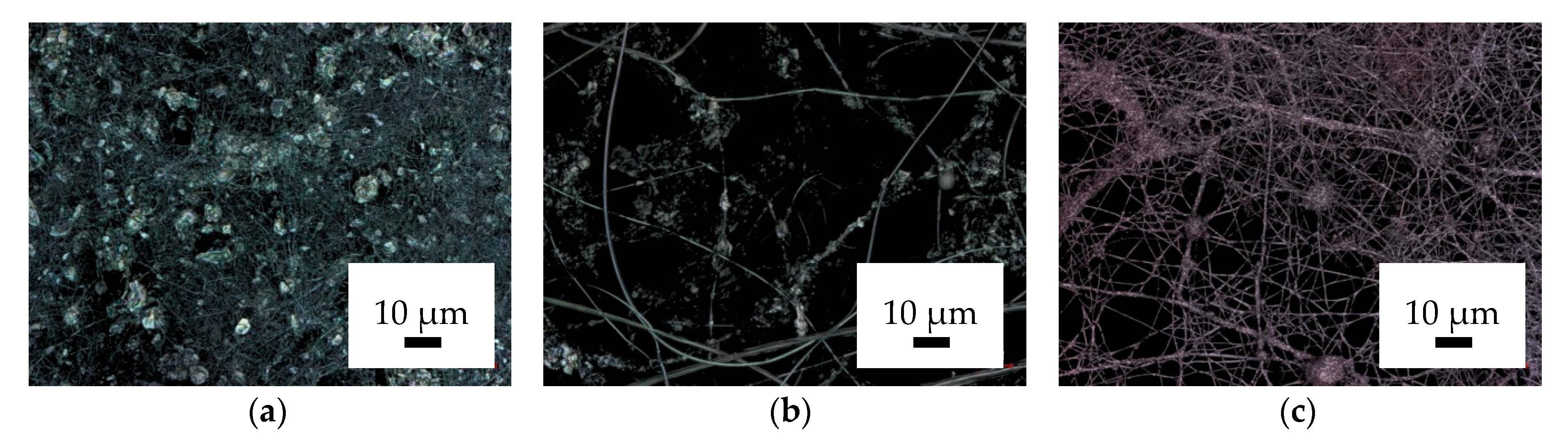
Figure 1 depicts confocal laser scanning microscope (CLSM) images of the polyacrylonitrile (PAN)/graphite nanofiber mat with and without a fine separation layer on top as well as the PAN/TiO2/dye nanofiber mat.
As Figure 1a shows, the graphite particles (with diameters of 4–6 µm) are much thicker than the nanofibers, preventing them from being integrated into the nanofibers. Instead, the graphite particles are arbitrarily spread over the nanofiber layer and are held by the fibers. To avoid a direct contact of the graphite particles with the TiO2 nanofiber mat, a thin PAN layer was electrospun on top. This is visible in Figure 1b as long straight fibers without attached graphite particles.
The nanofiber mat depicted in Figure 1c contains PAN as the spinning agent, the semiconductor TiO2, and two different anthocyanin-based natural dyes. Usually DSSCs are prepared by firstly applying a TiO2 layer, sintering it, and afterwards dyeing the layer. Here, the process was different—TiO2 nanoparticles and dye were mixed in the solution allowing for adsorption of dye molecules on the TiO2 nanoparticles, and the TiO2 was fixed by embedding it in the polymer matrix instead of sintering. The reddish color visible in Figure 1c, and even clearer recognizable by eye, indicates indeed that the dyes have retained their original color in the solution, which is more pink than lilac [29]. This is different from an earlier experiment in which pure PAN nanofiber mats were dip-coated in a TiO2 solution and afterwards dyed without a sintering step—in the latter study a strong bathochromic shift during dyeing was observed [30]. Although this finding indicates a low bonding of the dye molecules on the semiconductor, these nanofiber mats were investigated as possible front electrodes in DSSCs.
For this, the PAN/graphite nanofiber mat with the additional PAN layer and the PAN/TiO2/dye nanofiber mat were dip-coated in poly(3,4-ethylenedioxythiophene) polystyrene sulfonate (PEDOT:PSS) and left for drying on glass plates. Generally, this process leads to fully conductive nanofiber mats which would produce a short-circuit if put together in the form of a DSSC [31]. However, Reference [29] also indicates that the conductivity of nonconductive PAN nanofiber mats dip-coated in PEDOT:PSS significantly depends on the number of dip-coating cycles, suggesting that a thin layer of a not too highly viscous PEDOT:PSS may sink inside the nanofiber mat and in this way possibly reduce conductivity along the upper surface. This idea is supported by the finding that the additional PAN nanofibers on top of the PAN/graphite nanofiber mat strongly protrude from the fabric, as visible in Figure 1b.
Putting the nanofiber mats of the front electrode and the back electrode with dried PEDOT: PSS together shows indeed no short-circuit. Apparently, this simple method results in clearly separated conductive electrodes containing graphite as a catalyst for the back electrode and TiO2/dye for the front electrode, respectively.
After filling this fully electrospun DSSC with a conventional fluid electrolyte (based on iodine/triiodide) and stabilizing the cells with adhesive tape, measurements of their electrical characteristics were performed using a solar simulator to apply a light intensity of 100 mW/cm2. The same measurements were performed for the reference cells with only one electrospun electrode or two glass electrodes.
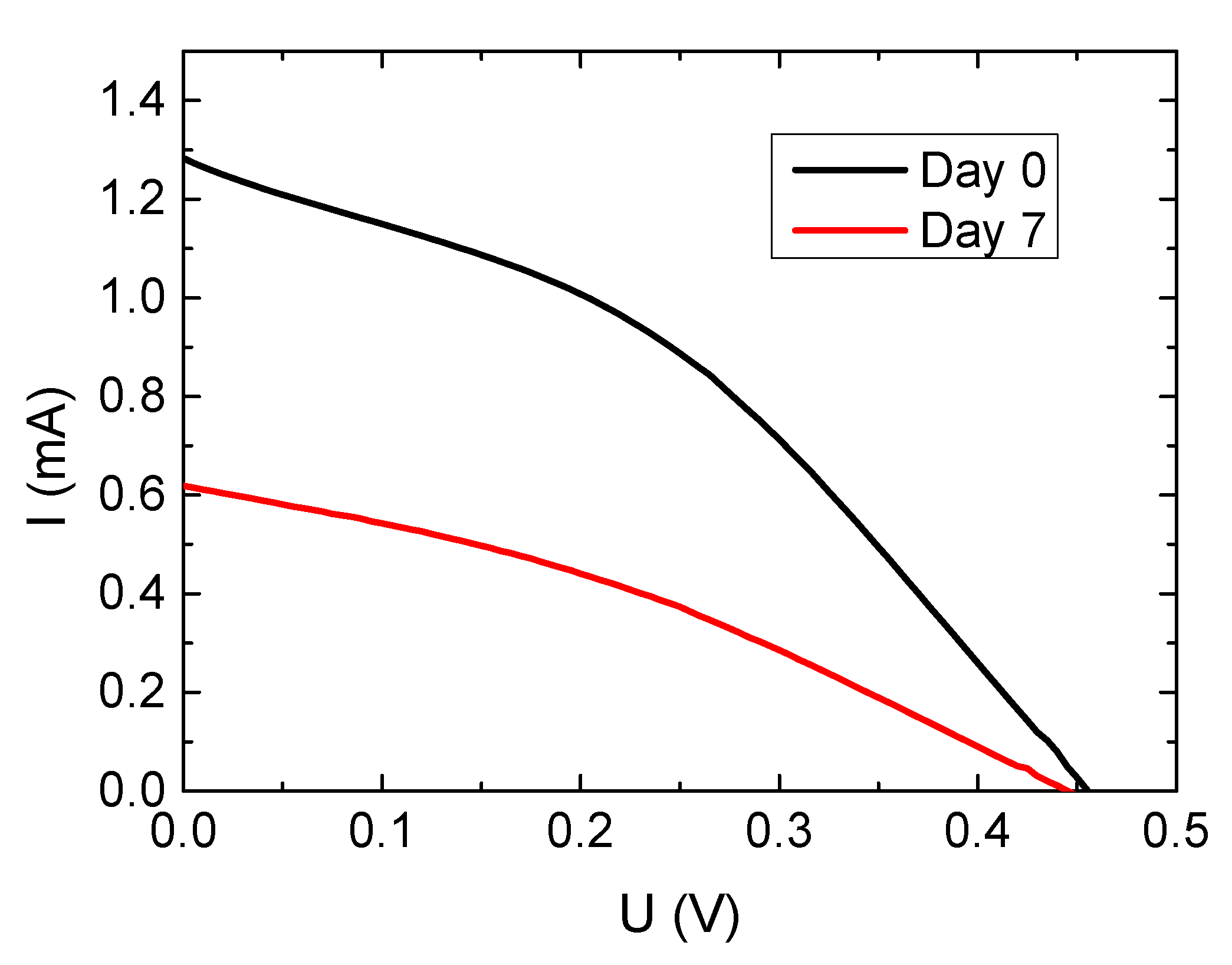
Figure 2 shows firstly the current-voltage characteristics of the fully glass-based reference cell with typical short-circuit currents and open-circuit voltages of DSSCs prepared with natural dyes as sensitizers. Since the cell is not sealed, evaporation of the electrolyte during the first week of measurements results in a reduction of the short-circuit current by approximately a factor of 2.
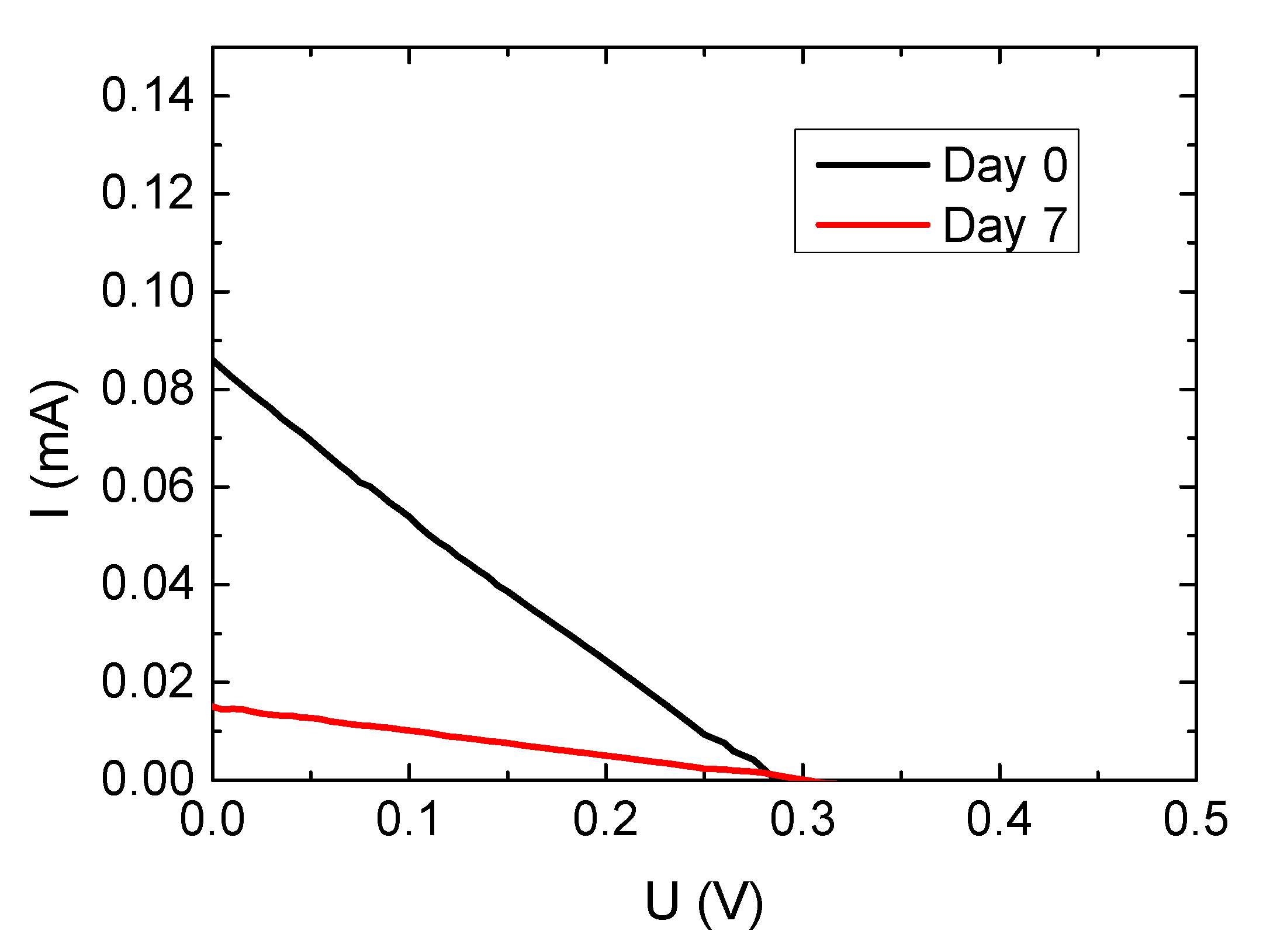
Next, Figure 3 depicts the current-voltage curves measured for the semi-nanofibrous DSSC. While the short-circuit current is reduced by one order of magnitude compared to the purely glass-based cell, it must be mentioned that the characteristics show a solar cell, not just a resistance, as it would be the case for a direct contact between the conductive part of the nanofiber mat and the conductive fluorine-doped tin oxide (FTO) glass. Generally, this DSSC works as a solar cell.
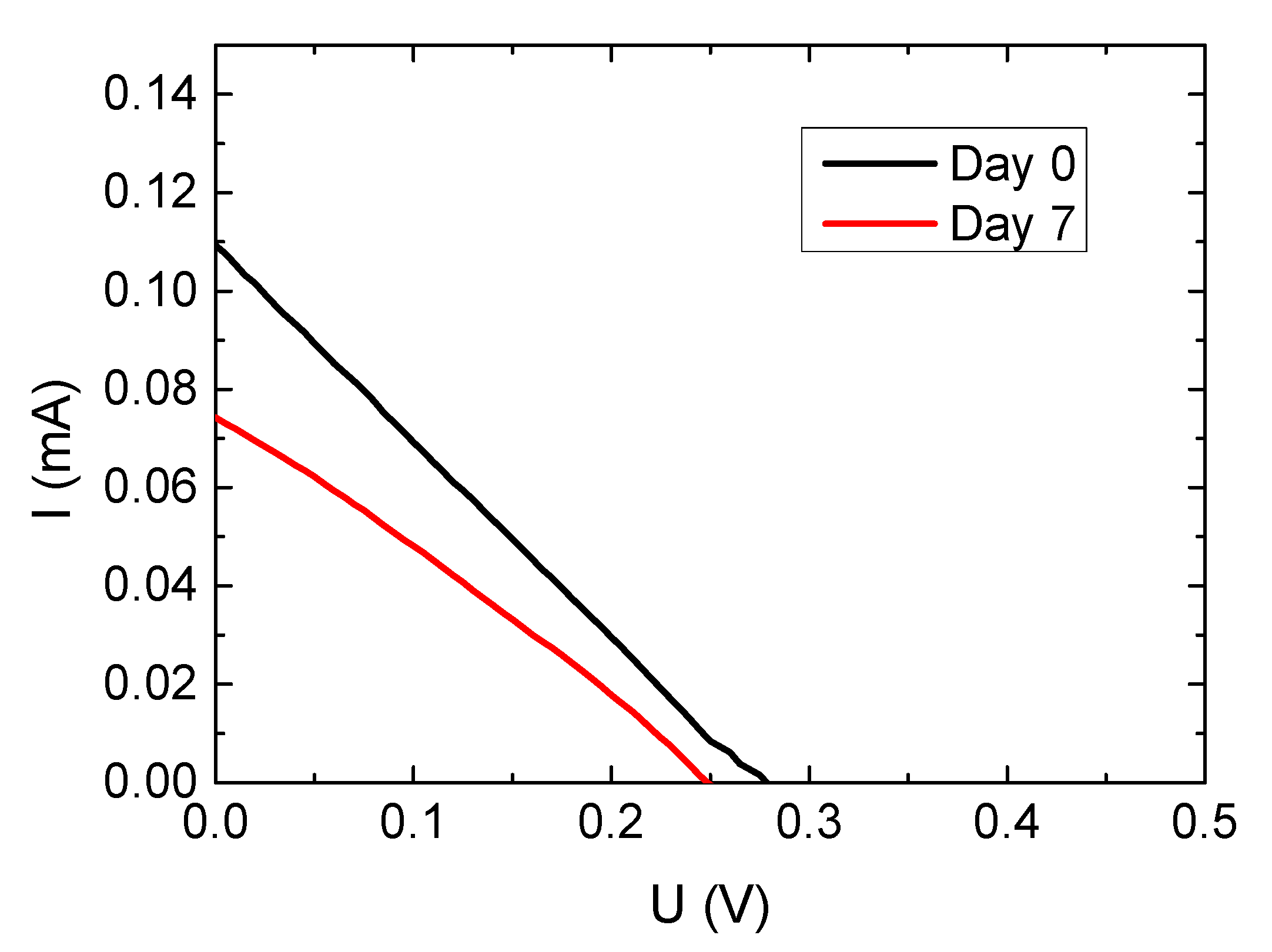
Finally, Figure 4 shows the characteristics of the fully electrospun nanofiber mat.
Surprisingly, short-circuit currents and fill factors are slightly higher than in the semi-nanofibrous cell. This is of special interest since the fully electrospun nanofiber mat does not have a transparent or at least translucent side through which the whole light of the solar simulator can penetrate into the cell. Typically, the transmission through an electrospun nanofiber mat, produced either from pure PAN or from PAN/TiO2, is in the range of 5–15%, depending on the wavelength [32]. Coating the nanofiber mat even with a thin PEDOT:PSS layer reduces the transmission further [31]. This indicates that while it is generally possible to prepare fully electrospun DSSCs, further research is necessary to improve the optical properties, especially the transmission through one of the electrodes, e.g., by preparing one electrode as a combination of nanofibrous mat and nanomembrane which is possible by tailoring the electrospinning parameters correspondingly [33].
It should also be mentioned that the decrease in short-circuit current is less pronounced than for the glass/nanofiber DSSCs, as depicted in Figure 3. The fully electrospun cell is significantly more stable within the first week of measurements. This measurement period, however, has to be extended to longer test series in future experiments.
All characteristic values of the three different samples, measured on day 0 and day 7 after preparation, are summarized in Table 1.
3. Discussion
The aim of this study was a proof-of-principle whether it is generally possible to produce all solid layers of a DSSC by electrospinning. As Figure 4 and Table 1 outline, this is clearly possible. Here, however, some approaches shall be discussed to improve the efficiency of such solar cells, which is necessary to use them for noteworthy energy harvesting. It should be mentioned that the general low efficiency of DSSCs based on natural dyes, as described in the Introduction, is not addressed here since our aim was using such environmentally-friendly non-toxic dyes instead of highly efficient but toxic dyes. Instead, the ideas discussed below to make fully electrospun DSSCs more efficient concentrate on morphological and material optimization approaches based on non-toxic materials. An additional reduction of the efficiency due to the relatively large cell area, as opposed to most other studies [21], can also not be avoided since larger cell areas make upscaling to larger scales easier than an approach based on smallest DSSC areas.
Besides the aforementioned approach to make one of the electrodes more translucent, Figure 1 reveals two more problems which must be solved in future experiments. Firstly, the graphite layer is not closed (Figure 1a), and the contact with the conductive PEDOT:PSS coating is not assured. This means on the one hand that not the whole PEDOT:PSS surface serves as the counter electrode, since graphite or a similar catalyst is necessary to support re-entrance of electrons into the DSSC through the counter electrode. A simple comparison of glass-based cells with and without graphite coating on the counter electrode shows an increase of more than one order of magnitude due to the graphite coating. This underlines that a more even graphite distribution is necessary. Possible approaches to solve this problem include on the one hand testing carbon black, typically showing much smaller diameters than the graphite flakes used here, as a dopant for the PAN nanofibers. Due to the smaller diameters, it can be expected that carbon black is integrated in the polymer fibers or acts as a coating on their surface and thus offers a higher contact area with the PEDOT:PSS serving as the actual counter electrode. On the other hand, using a pure PAN nanofiber mat as counter electrode and dip-coating it in PEDOT:PSS blended with carbon black will also need to be investigated.
Second, as mentioned before, the dye is not adsorbed on the TiO2 nanoparticles in the fibers, as clearly indicated by the missing bathochromic shift (Figure 1c). This is of special importance since the general low efficiency of DSSCs based on natural dyes is attributed to low bonding between dye molecules and semiconductor, a problem which is here clearly visible and must be solved. A possible solution was already suggested in Reference [28], showing that TiO2 can be adhered inside a PAN nanofiber mat and dyed there unambiguously, resulting in the desired adsorption of anthocyanin dye molecules on the semiconductor. This technique, however, must be tested in combination with the simple way of dip-coating nanofiber mats in PEDOT:PSS to make only a part of them conductive as suggested here.
Finally, solid or gel-based electrolytes should be tested to prepare a fully textile DSSC without any fluid inside which would evaporate with time.
It should be mentioned that these suggested optimization steps, while necessitating a certain development time, will finally result in an as easy experimental approach as described here. The general simplicity of the electrospinning process will, opposite to more sophisticated methods necessitating handling fine wires etc., enable a fast and easy process which can simply be upscaled to an industrial scale. This possibility paves the way to large-scale textile DSSCs produced from non-toxic, low-cost materials, as opposed to other fiber-based solutions mainly aiming at a high efficiency at the cost of sustainability, ease of production, and scalability.
With these approaches, an increase of the efficiency and the long-term stability can be expected, which would make purely textile, fully flexible DSSCs competitive with glass-based DSSCs.
4. Materials and Methods
The DSSCs used in this study were prepared by two electrospinning steps. For the counter electrode, a solution of 2.89 g X-PAN (Dralon GmbH, Lingen, Germany) and 4.90 g graphite powder (particles diameter 4–6 µm, purchased from Algin, Neustadt Glewe/Germany) in 18.05 g dimethyl sulfoxide (DMSO, min 99.9%, purchased from S3 Chemicals, Bad Oeynhausen, Germany) was prepared. The thin separation layer on top of the counter electrode was electrospun from 16% X-PAN in DMSO. For the front electrode, a solution of 41.2 g DMSO, 5.0 g forest fruit tea (Mayfair, Wilken Tee GmbH, Fulda, Germany), 10.0 g TiO2 (P25 Titanium IV oxide nanopowder, 21 nm primary particle size, Sigma Aldrich, Saint Louis, MO, USA), and 6.7 g X-PAN was used. Directly before electrospinning, 3 g black bean extract (Badmonkey Botanicals, Tacoma, WA 98448, USA) was added to counteract the possible photo-degradation of the anthocyanins in the tea by the TiO2.
Electrospinning was performed in a needleless electrospinning machine “Nanospider Lab” (Elmarco Ltd., Liberec, Czech Republic). The spinning parameters used here were: high-voltage 80 kV, nozzle diameter 0.8 mm (front electrode) or 1.5 mm (back electrode), carriage speed 100 mm/s, bottom electrode/substrate distance 240 mm, ground electrode/substrate distance 50 mm, temperature in the chamber 24 °C, and relative humidity in the chamber 32%.
Afterwards, the nanofiber mats were dip-coated in PEDOT:PSS purchased from Sigma-Aldrich Chemie GmbH, Munich, Germany), placed on glass plates (in case of the counter electrode with the separation layer on top), and left for drying. Finally, the electrodes were pressed together and fixed with adhesive tape before the iodine/triiodide electrolyte (from Man Solar, Petten, The Netherlands) was filled in. The efficient cell area was 6 cm2.
Reference cells of identical cell areas were performed using FTO (fluorine-doped tin oxide) coated glasses (Man Solar) for both electrodes, in case of the front electrode using FTO glasses coated with TiO2, or only the counter electrode. The catalyst on the latter was applied by a graphite pencil.
The nanofiber mat morphologies were investigated using a confocal laser scanning microscope (CLSM) VK-8710 (Keyence, Neu-Isenburg, Germany). Measuring current-voltage curves of the DSSCs was performed with a Keithley 2450 sourcemeter, while the samples were illuminated with a solar simulator LS0500 with AM 1.5 G spectrum (LOT-Quantum Design GmbH, Darmstadt, Germany) applying 100 mW/cm2. All values were averaged over 3 nominally identical samples.
5. Conclusions
This study revealed that in general, all solid layers of a DSSC can be electrospun. Without any further optimization, short-circuit currents are approximately one order of magnitude lower than for the glass-based reference cell. Thus, different approaches are suggested to further increase the efficiency of the fully textile DSSC and to pave a way to its utilization in real textile-based applications.
Author Contributions
Conceptualization, S.K. and I.J.J.; methodology, S.K. and D.W.; formal analysis, S.K.; investigation, S.K., D.W. and A.E.; writing—original draft preparation, A.E.; writing—review and editing, all authors; visualization, A.E.
Funding
This research was funded by Deutsche Bundesstiftung Umwelt DBU (German Federal Environmental Foundation), HiF funds of Bielefeld University of Applied Sciences, and the PhD funds of Bielefeld University of Applied Sciences. The APC is funded by the Open Access Publication Fund of Bielefeld University of Applied Sciences and the Deutsche Forschungsgemeinschaft (DFG, German Research Foundation)–414001623.
Acknowledgments
The publication of this article was funded by Bielefeld University of Applied Sciences.
Conflicts of Interest
The authors declare no conflict of interest. The funders had no role in the design of the study; in the collection, analyses, or interpretation of data; in the writing of the manuscript; or in the decision to publish the results.
References
- Kleidon, A. Sonne statt Flaute. Phys. Unserer Zeit 2019, 50, 120–127. [Google Scholar] [CrossRef]
- Hashmi, G.A.M.; Syed, W.A.A.; Hayat, M.; Shah, W.H.; Shah, N.A. SrCl2 an environment friendly alternate to CdCl2 treatment for CdTe thin films solar cell application. Mater. Res. Express 2019, 6, 106440. [Google Scholar] [CrossRef]
- Liu, Y.H.; Chen, C.; Zhou, Y.; Kondrotas, R.; Tang, J. Butyldithiocarbamate acid solution processing: Its fundamentals and applications in chalcogenide thin film solar cells. J. Mater. Chem. C 2019, 7, 11068–11084. [Google Scholar] [CrossRef]
- Siddiqui, H. Lead-free perovskite quantum structures towards the efficient solar cell. Mater. Lett. 2019, 249, 99–103. [Google Scholar] [CrossRef]
- Hong, L.; Yao, H.F.; Wu, Z.; Cui, Y.; Zhang, T.; Xu, Y.; Yu, R.N.; Liao, Q.; Gao, B.W.; Xian, K.H.; et al. Eco-Compatible Solvent-Processed Organic Photovoltaic Cells with Over 16% Efficiency. Adv. Mater. 2019, 31, 1903441. [Google Scholar] [CrossRef]
- Freitag, M.; Teuscher, J.; Saygili, Y.; Zhang, X.Y.; Giordano, F.; Liska, P.; Hua, J.L.; Zakeeruddin, S.M.; Moser, J.-E.; Grätzel, M.; et al. Dye-sensitized solar cells for efficient power generation under ambient lighting. Nat. Photonics 2017, 11, 372–378. [Google Scholar] [CrossRef]
- Zhou, H.Z.; Wu, L.Q.; Gao, Y.R.; Ma, T.L. Dye-sensitized solar cells using 20 natural dyes as sensitizers. J. Photochem. Photobiol. A 2011, 219, 188–194. [Google Scholar] [CrossRef]
- Narayan, M.R. Review: Dye sensitized solar cells based on natural photosensitizers. Renew. Sustain. Energy Rev. 2012, 16, 208–215. [Google Scholar] [CrossRef]
- Calogero, G.; Marco, G.D.; Cazzanti, S.; Caramori, S.; Argazzi, R.; Carlo, A.D.; Bignozzi, C.A. Efficient dye-sensitized solar cells using red turnip and purple wild Sicilian prickly pear fruits. Int. J. Mol. Sci. 2010, 11, 254–267. [Google Scholar] [CrossRef]
- Kabir, F.; Sakib, S.N.; Uddin, S.S.; Efaz, E.T.; Himel, M.T.F. Enhance cell performance of DSSC by dye mixture, carbon nanotube and post TiCl4 treatment along with degradation study. Sustain. Energy Technol. Assess. 2019, 35, 298–307. [Google Scholar] [CrossRef]
- Alhamed, M.; Issa, A.S.; Doubal, A.W. Studying of natural dyes properties as photo-sensitizers for dye sensitized solar cells (DSSC). J. Electron Dev. 2012, 16, 1370–1383. [Google Scholar]
- Al-Bath’hi, S.A.M.; Alaei, I.; Sopyan, I. Natural photosensitizers for dye sensitized solar cells. Int. J. Renew. Energy Res. 2013, 3, 138–143. [Google Scholar]
- Juhász Junger, I.; Homburg, S.V.; Meissner, H.; Grethe, T.; Schwarz-Pfeiffer, A.; Fiedler, J.; Herrmann, A.; Blachowicz, T.; Ehrmann, A. Influence of the pH value of anthocyanins on the electrical properties of dye-sensitized solar cells. AIMS Energy 2017, 5, 258–267. [Google Scholar] [CrossRef]
- Lucioli, S.; Di Bari, C.; Forni, C.; Di Carlo, A.; Barrajón-Catalán, E.; Micol, V.; Nota, P.; Teoli, F.; Matteocci, F.; Frattarelli, A.; et al. Anthocyanic pigments from elicited in vitro grown shoot cultures of Vaccinium corymbosum L., cv. Brigitta Blue, as photosensitizer in natural dye-sensitized solar cells (NDSSC). J. Photochem. Photobiol. B 2018, 188, 69–76. [Google Scholar] [CrossRef]
- Li, Y.; Ku, S.-H.; Chen, S.-M.; Ali, M.A.; AlHemaid, F.M.A. Photoelectrochemistry for red cabbage extract as natural dye to develop a dye-sensitized solar cell. Int. J. Electrochem. Sci. 2013, 8, 1237–1245. [Google Scholar]
- Gokilamani, N.; Muthukumarasamy, N.; Thambidurai, M.; Ranjitha, A.; Velauthapillai, D. Utilization of natural anthocyanin pigments as photosensitizers for dye-sensitized solar cells. J. Sol-Gel Sci. Technol. 2013, 66, 212–219. [Google Scholar] [CrossRef]
- Wongcharee, K.; Meeyoo, V.; Chavadej, S. Dye-sensitized solar cell using natural dyes extracted from rosella and blue pea flowers. Sol. Energy Mater. Sol. Cells 2007, 91, 566–571. [Google Scholar] [CrossRef]
- Senthil, T.S.; Muthukumarasamy, N.; Velauthapillai, D.; Agilan, S.; Thambidurai, M.; Balasundaraprabhu, R. Natural dye (cyanidin 3-O-glucoside) sensitized nanocrystalline TiO2 solar cell fabricated using liquid electrolyte/quasi-solid-state polymer electrolyte. Renew. Energy 2011, 36, 2484–2488. [Google Scholar] [CrossRef]
- Hao, S.C.; Wu, J.H.; Huang, Y.F.; Lin, J.M. Natural dyes as photosensitizers for dye-sensitized solar cell. Sol. Energy 2006, 80, 209–214. [Google Scholar] [CrossRef]
- Ehrmann, A.; Blachowicz, T. Comment on ‘Dye-sensitized solar cells using Aloe Vera and Cladode of Cactus extracts as natural sensitizers’. Chem. Phys. Lett. 2019, 714, 227–229. [Google Scholar] [CrossRef]
- Juhász Junger, I.; Udomrungkhajornchai, S.; Grimmelsmann, N.; Blachowicz, T.; Ehrmann, A. Effect of Caffeine Copigmentation of Anthocyanin Dyes on DSSC Efficiency. Materials 2019, 12, 2692. [Google Scholar] [CrossRef] [PubMed]
- Ehrmann, A.; Blachowicz, T. Recent coating materials for textile-based solar cells. AIMS Mater. 2019, 6, 234–251. [Google Scholar] [CrossRef]
- Herrmann, A.; Fiedler, J.; Ehrmann, A.; Grethe, T.; Schwarz-Pfeiffer, A.; Blachowicz, T. Examination of the sintering process dependent micro- and nanostructure of TiO2 on textile substrates. Proc. SPIE 2016, 9898, 98980S. [Google Scholar]
- Opwis, K.; Gutmann, J.S.; Lagunas Alonso, A.R.; Rodriguez Henche, M.J.; Mayo, M.E.; Breuil, F.; Leonardi, E.; Sorbello, L. Preparation of a textile-based dye-sensitized solar cell. Int. J. Photoenergy 2016, 2016, 3796074. [Google Scholar] [CrossRef]
- Jun, M.J.; Cha, S.I.; Seo, S.H.; Kim, H.S.; Lee, D.Y. Float printing deposition to control the morphology of TiO2 photoanodes on woven textile metal substrates for TCO-free flexible dye-sensitized solar cells. RSC Adv. 2016, 6, 67331–67339. [Google Scholar]
- Pu, X.; Song, W.X.; Liu, M.M.; Sun, C.W.; Du, C.H.; Jiang, C.Y.; Huang, X.; Zou, D.; Hu, W.G.; Wang, Z.L. Wearable power-textiles by integrating fabric triboelectric nanogenerators and fiber-shaped dye-sensitized solar cells. Adv. Energy Mater. 2016, 6, 1601048. [Google Scholar] [CrossRef]
- Chai, Z.S.; Zhang, N.N.; Sun, P.; Huang, Y.; Zhao, C.X.; Fan, H.J.; Fan, X.; Mai, W.J. Tailorable and wearable textile devices for solar energy harvesting and simultaneous storage. ACS Nano 2016, 10, 9201–9207. [Google Scholar] [CrossRef]
- Chen, J.; Huang, Y.; Zhang, N.N.; Zou, H.Y.; Liu, R.Y.; Tao, C.Y.; Fan, X.; Wang, Z.L. Micro-cable structured textile for simultaneously harvesting solar and mechanical energy. Nat. Energy 2016, 1, 16138. [Google Scholar] [CrossRef]
- Kohn, S.; Großerhode, C.; Storck, J.L.; Grötsch, G.; Cornelißen, C.; Streitenberger, A.; Grassmann, C.; Schwarz-Pfeiffer, A.; Ehrmann, A. Commercially available teas as possible dyes for dye-sensitized solar cells. Optik 2019, 185, 178–182. [Google Scholar] [CrossRef]
- Mamun, A.; Trabelsi, M.; Klöcker, M.; Sabantina, L.; Großerhode, C.; Blachowicz, T.; Grötsch, G.; Cornelißen, C.; Streitenberger, A.; Ehrmann, A. Electrospun Nanofiber Mats with Embedded Non-Sintered TiO2 for Dye-Sensitized Solar Cells (DSSCs). Fibers 2019, 7, 60. [Google Scholar] [CrossRef]
- Juhász Junger, I.; Wehlage, D.; Böttjer, R.; Grothe, T.; Juhász, L.; Grassmann, C.; Blachowicz, T.; Ehrmann, A. Dye-Sensitized Solar Cells with Electrospun Nanofiber Mat-Based Counter Electrodes. Materials 2018, 11, 1604. [Google Scholar] [CrossRef] [PubMed]
- Kerker, E.; Steinhäußer, D.; Mamun, A.; Trabelsi, M.; Fiedler, J.; Sabantina, L.; Juhász Junger, I.; Schiek, M.; Ehrmann, A.; Kaschuba, R. Spectroscopic Investigation of Highly-Scattering Nanofiber Mats during Drying and Film Formation. Optik 2020. submitted. [Google Scholar]
- Sabantina, L.; Hes, L.; Rodríguez-Mirasol, J.; Cordero, T.; Ehrmann, A. Water Vapor Permeability through PAN Nanofiber Mat with Varying Membrane-Like Areas. Fibres Text. East. Eur. 2019, 27, 12–15. [Google Scholar] [CrossRef]
Figure 1.
CLSM images of different nanofiber mats: (a) PAN/graphite; (b) PAN on top of PAN/graphite; (c) PAN/TiO2/dye.
Figure 1.
CLSM images of different nanofiber mats: (a) PAN/graphite; (b) PAN on top of PAN/graphite; (c) PAN/TiO2/dye.

Figure 2.
Current-voltage (I-U) characteristics of a glass-based DSSC, prepared with an anthocyanin-based dye.
Figure 2.
Current-voltage (I-U) characteristics of a glass-based DSSC, prepared with an anthocyanin-based dye.

Figure 3.
Current-voltage (I-U) characteristics of a glass/nanofiber mat DSSC, prepared with an anthocyanin-based dye. The y-axis differs from Figure 2.
Figure 3.
Current-voltage (I-U) characteristics of a glass/nanofiber mat DSSC, prepared with an anthocyanin-based dye. The y-axis differs from Figure 2.

Figure 4.
Current-voltage (I-U) characteristics of a pure nanofiber mat DSSC, prepared with an anthocyanin-based dye. The y-axis is identical with Figure 3.
Figure 4.
Current-voltage (I-U) characteristics of a pure nanofiber mat DSSC, prepared with an anthocyanin-based dye. The y-axis is identical with Figure 3.


Table 1.
Electric characteristics of the samples presented here, giving the short-circuit current density (JSC), the open-circuit voltage (UOC), the fill factor (FF), and the efficiency.
Table 1.
Electric characteristics of the samples presented here, giving the short-circuit current density (JSC), the open-circuit voltage (UOC), the fill factor (FF), and the efficiency.
| Sample | JSC/mA | UOC/V | FF | Efficiency/% |
|---|---|---|---|---|
| Ref. glass–day 0 | 0.214 | 0.455 | 0.383 | 0.037 |
| Ref. glass–day 7 | 0.103 | 0.445 | 0.339 | 0.016 |
| Glass + nanofiber mat–day 0 | 0.015 | 0.290 | 0.246 | 0.0011 |
| Glass + nanofiber mat–day 7 | 0.003 | 0.305 | 0.265 | 0.0002 |
| Full nanofiber DSSC–day 0 | 0.019 | 0.280 | 0.259 | 0.0014 |
| Full nanofiber DSSC–day 7 | 0.013 | 0.260 | 0.283 | 0.0010 |
© 2019 by the authors. Licensee MDPI, Basel, Switzerland. This article is an open access article distributed under the terms and conditions of the Creative Commons Attribution (CC BY) license (http://creativecommons.org/licenses/by/4.0/).
Share and Cite
MDPI and ACS Style
Kohn, S.; Wehlage, D.; Juhász Junger, I.; Ehrmann, A. Electrospinning a Dye-Sensitized Solar Cell. Catalysts 2019, 9, 975. https://0-doi-org.brum.beds.ac.uk/10.3390/catal9120975
AMA Style
Kohn S, Wehlage D, Juhász Junger I, Ehrmann A. Electrospinning a Dye-Sensitized Solar Cell. Catalysts. 2019; 9(12):975. https://0-doi-org.brum.beds.ac.uk/10.3390/catal9120975
Chicago/Turabian StyleKohn, Sophia, Daria Wehlage, Irén Juhász Junger, and Andrea Ehrmann. 2019. "Electrospinning a Dye-Sensitized Solar Cell" Catalysts 9, no. 12: 975. https://0-doi-org.brum.beds.ac.uk/10.3390/catal9120975
Note that from the first issue of 2016, this journal uses article numbers instead of page numbers. See further details here.