2. Lean Steam/gas (Ratio) Sulfur Tolerant Water Gas Shift
The WGS system mainly contains five general compounds, i.e., CO, CO2, H2, H2O and CH4, which are supposed to maintain a balance under given reaction conditions. Two reactions proceed in a parallel way to decide the final product composition.
- (1)
Water gas shift as the main reaction
- (2)
Methanation of CO as the core side reaction
WGS reaction is mildly exothermic while methanation is commonly known as strongly exothermic. Intensive methanation consumes H
2; in addition, it often leads to an unpredictable, suddenly raised catalyst bed temperature which causes the damage of catalyst structure. In the real industrial process of syngas refining, to obtain a satisfied CO/H
2 ratio, methanation should be strictly avoided in the WGS section [
1,
2,
15,
16]. One useful method is to overfeed the content of water (steam) in the reactant stream which helps to selectively promote the WGS main reaction while effectively suppressing methanation with the reaction equilibrium; thus, a high steam/gas (dry syngas without water) ratio should be applied. For SWGS in the coal/natural gas industry, the steam/gas ratio employed by a pre-reactor (R1) is routinely 1.6 or higher [
12,
13,
17].
Water (steam) consumption became another challenge when a high steam/gas ratio was applied. On the other hand, the overfed steam used to avoid methanation may also overpromote WGS reaction with an equilibrium temperature interval up to several hundred degrees. In such case, the control of WGS reaction depth became undesirably difficult and therefore the catalyst bed temperature rapidly went up. The only way to avoid superfluous heat was reducing the actual catalyst loading for each reactor [
13,
17].
With modified anti-methanation and water-capture features, SWGS catalysts can be used under lean (lower) steam/gas ratio (0.5 or lower) conditions. It was until 2003 that the world’s first industrialization of SWGS with a lean steam/gas ratio was successfully applied in China [
13,
14]. Some plants have been smoothly running for more than 10 years with an average catalyst lifetime of 3–4 years. The adoption of such catalysts requires changes in technological process as explained in
Figure 1 [
17].
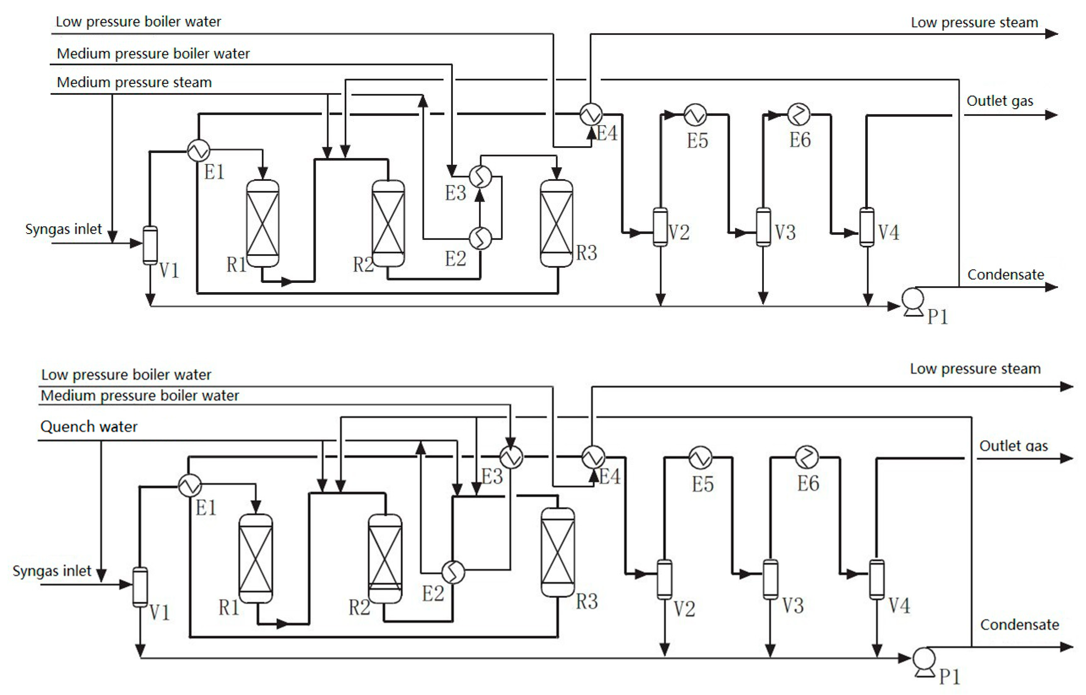
When applied in the SWGS process (
Figure 1), high steam/gas ratio technology (HSGRT) does not require water complementation before a 2nd WGS reactor (R3); however, medium pressure steam used for a reaction will be added into the pre WGS reactor (R1) and 1st WGS reactor (R2), respectively. Instead of steam, lean steam/gas ratio technology (LSGRT) possesses three quench water injections in front of R1, R2 and R3, respectively. In each reactor quench, water vaporized into steam with heat is released from the reaction (there is no need to use out heat), and such improvement has been proven to effectively reduce the actual plant steam consumption and energy cost with the WGS (SWGS) reaction rate being better controlled by the injected quench water amount [
17].
Table 1 presents the real industrial data obtained from a 0.5 million ton/year methanol synthesis project (Zhong Yuan Da Hua Coal Chemistry Group, Henan Province, China) employed Shell gasification for syngas production.
As the original steam/gas ratio (~0.3 or higher) of crude syngas had already satisfied the requirement for LSGRT, there was no water complementary, either in terms of steam or quench water. The steam cost (35–60 ton/hour) fell to nearly zero by technological upgrade from HSGRT to LSGRT. On the other hand, the condensed water generation correspondingly reduced from 30–55 ton/hour to 0–5 ton/hour. Noteworthily, with no extra steam added, the steam/gas ratio of each reactor could be maintained at a uniform (0.23–0.26) by LSGRT as a significant advance. At the same time, with the steam (water) amount inside SWGS system steadily controlled, methanation was effectively suppressed and the undesired catalyst bed temperature ‘flying away’ (the suddenly occurred temperature increasement due to methanation) was also prohibited.
Industrial data from the SWGS plants of a 4 million ton/year Coal-to-Liquid project (Shenhua Ningxia Coal Industry Group, Ningxia Province, China) are more encouraging. The project employed GSP gasification (pressurized pulverized coal gasification) to give an initial steam/gas ratio of ~1.0 for the raw syngas, which already exceeded the steam usage requirement for LSGRT. After upgrading to LSGRT, there was no need to add extra steam into the SWGS process; for a single SWGS reactor R2, the overall saved cost on steam was approximately 1.04 × 10⁹ RMB, equivalent to 1.52 × 10⁸ USD every year.
3. Catalysts Used for Lean Steam/Gas (Ratio) Sulfur Tolerant Water Gas Shift
Syngas from the gasification and partial oxidation of heavy oil, tar sands, coal, coke or biomass contain much larger concentrations of CO (up to 50 mol%) and sulfur levels of 5–50 ppm, as a result of which both sulfur tolerance and effective CO activation are crucial for conventional SWGS catalysts. A standard commercial SWGS catalyst composition is based on Co (Ni)-Mo/alumina, here the core catalytic function relies on the effective CO activation of sulfurized Mo sites while other metal species, e.g., Cobalt, are co-catalytic sites or promoters helping in the effective electron transportations [
10,
11,
18,
19,
20]. The accelerated CO conversion requires more water molecules to finish the reaction. It is, hence, necessary to either operate at higher steam/gas (or H
2O/CO) ratios or use extra volume of catalysts to support the desired CO conversion [
10,
11,
18,
19,
20,
21].
One question is to what extent the water molecules used by high steam/gas conditions are utilized to successfully convert CO into CO
2, or whether the enriched water concentration would affect the WGS reaction in practice. Herein, the interaction between catalytic sites and water molecules becomes a key point. The secret behind LSGRT for SWGS is its
enhanced water (steam) capture by employed catalyst [
13]. It is well known that the WGS catalyst promotes both water gas shift and methanation reactions. In a closed system reaction equilibrium works to draw the final product composition; however, in a constant flow system, e.g., the WGS reactor, the utilization of catalytic sites by different reactants dominates the product output [
12,
18,
21]. By applying a specially designed SWGS catalyst with better water-capture ability, H
2O molecules were selectively enriched on/near the catalytic sites to meet the requirement of accelerated CO conversions, while the H
2 adsorption on catalytic sites was effectively weakened. The first effect greatly promotes the WGS reaction and enables step-wised control of WGS reaction depth with even very limited water amount; the second effect better suppresses the methane formation.
Inclusion of alkali oxides into the Mo–Co/alumina composition brings the above enhanced water capture ability to LSGRT SWGS catalysts. The increase of K
2O content in MgAl
2O
4 spinel modified alumina supported CoMoOx catalyst (general form of conventional Mo–Co/Al
2O
3 catalyst for SWGS) led to higher CO conversions under the lean steam/gas conditions while effectively suppressing the formation of CH
4 [
13,
14]. It was thought that K
2CO
3 helped in the capture of water molecules while the alkalinity of K
2CO
3 also effectively depressed methane formation over the MoS
2 active sites.
A general composition of industrial Mo–Co/alkali/Al2O3 catalyst for LSGRT is given as below (based on the evaluation of X-ray fluorescence spectroscopy, atom weight):
Na 1–3%, Mg 0–1%, Al 65–80%, K 0–15%, Ca 0–5%, Mo 5–10%, and Co 0–5%.
In this paper, we have selected representative samples of a laboratory-developed LSGRT SWGS catalyst (marked as CAT) that has been and is being employed in the SWGS plant of many large scale coal/natural-gas chemistry projects in the Chinese industry. Samples of different running time, and various deactivations were characterized and re-evaluated in laboratory.
4. Catalyst Performances and Characterizations
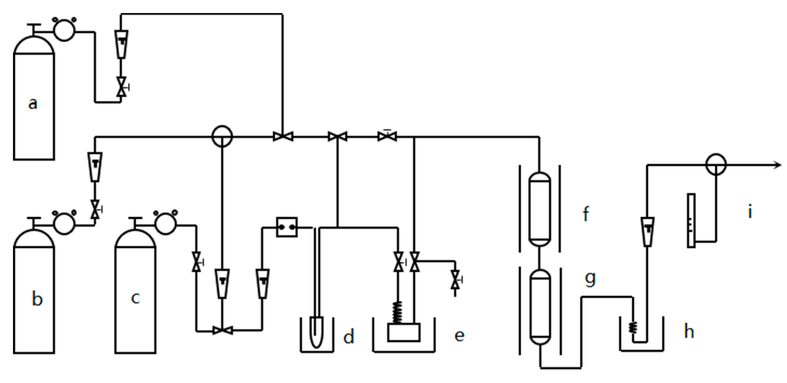
Residual catalytic properties of served/deactivated samples were measured by rationally designed laboratory experiments using as-prepared (sulfurized in factory) CAT for reference. The experimental system (
Figure 2) employed two fixed-bed reactors connected in series in order to better simulate the real SWGS process (R1 used for pre-sulfurization was removed to show the authentic residual catalytic property of served/deactivated industrial samples, all samples were vacuumed immediately at the time of unloading; the reactor 1 and reactor 2 in
Figure 2 simulated the R2 and R3 SWGS reactors in
Figure 1, respectively). Each time, 0.3 ml catalysts ground and sieved into 40–60 mesh were loaded in the isothermal zone of each reactor (quartz wool and quartz sand were used for protection and supporting). N
2 (100 ml/min) was used as a carrier gas to bring steam into the reactors. Water was vaporized in the calibrated two-stage evaporators, and the steam/gas ratio was precisely set at 0.7, a bit higher than the real LSGRT to guarantee the CO conversion over served/deactivated samples. The inlet dry gas (50 ml/min) contained CO of 45 vol%, CO
2 of 5 vol%, H
2 ~50 vol% and H
2S 3000 ppm to make sure a syngas GHSV of 10000 h
–1. It should be noted that the composition of industrial syngas as raw materials to SWGS plants does vary a lot due to many issues, such as the coal type, employed gasifiers and the exact gasifying technologies [
21,
22,
23]. The syngas composition employed in this research, especially the CO content has considered the suggestions from field experts, plant designers, and more importantly the practical CO vol% of several representative commercialized gasifications (typical slurry feed entrained-flow gasifier, e.g., Chevron Texaco Gasifier, gives 30–45 vol% CO; dry feed entrained-flow gasifier, e.g., Shell Gasifier, may give CO percentage of ~60 vol%) [
22,
23,
24,
25]. In order to extend the catalytic lifetime for deactivated samples and for a safety consideration, industrial 3Mp pressure was not employed and all samples were tested under atmosphere pressure; however, as the reaction is volume constant, the current system causes very limited discrepancy in the catalytic property evaluations.
Catalytic performances of different samples at three temperature points (265 °C, 350 °C and 450 °C) are presented in
Figure 3 and
Figure 4, respectively. At each temperature, the catalyst samples were stabilized in N
2 for 1h ahead of test. The reactor outlet flow was analyzed with on-line gas chromatography (Agilent 7890, packed column 1.5 m Φ 3 mm, TCD, FID and FPD). The catalytic performance was measured by CO conversion:
It is clearly shown in
Figure 3, longer-time served CAT always led to a lower CO conversion in the same laboratory experiment, which is an intuitionistic sign of catalyst ‘aging to deactivate’. All samples exhibited very low CO conversion at 265 °C which implies a higher temperature is required for the sufficient catalytic activation. At 450 °C, all samples achieved CO conversion of 10 mol% or much higher (70 mol%). Interestingly, CO conversion at 350 °C showed a huge difference between samples used for 3 and 4 years, while at 450 °C, the difference between these two samples was less. To answer the above question, two notes could be addressed: 1) 310–450 °C is the proper temperature range of industrial High-Temperature WGS (HTS). For HTS, a higher temperature, i.e., 450 °C, possesses more influence on the reaction rate, which could minimize the actual CO conversion difference between differently aged catalysts especially in a stream reactor (*It should be noted that raising catalyst bed temperature is a common way to extend the lifetime of less catalytic, aged catalysts in the chemistry industry although coke formation may also be fastened at the same time) [
1,
4,
12,
16,
18]. 2) WGS at 350 °C or below relies more on the reserved intrinsic properties of the employed catalyst, thus, the poorer performance of 4 years served CAT was amplified. The above results support recent studies focusing on the development of a lower temperature WGS catalyst; the aim of such exploration is to speed up catalytic performance at 300 °C or lower while taking the advantage of WGS reaction equilibrium (WGS process is moderately exothermic) [
1,
6,
7,
8].
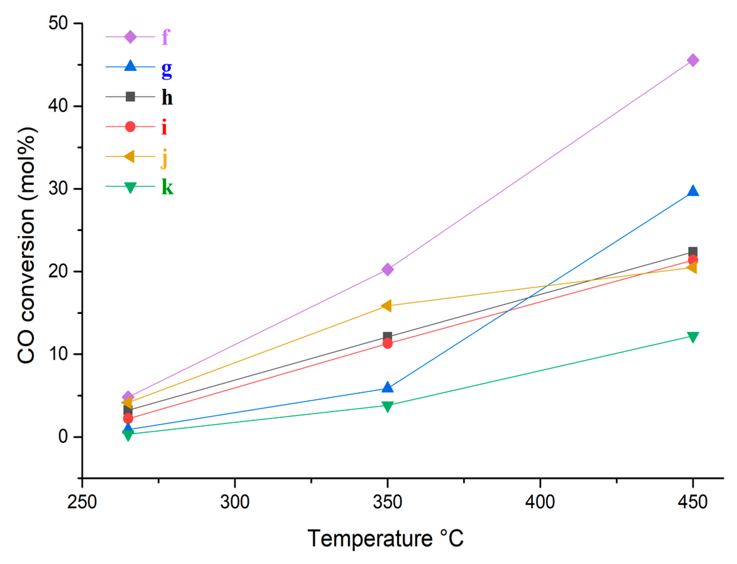
In
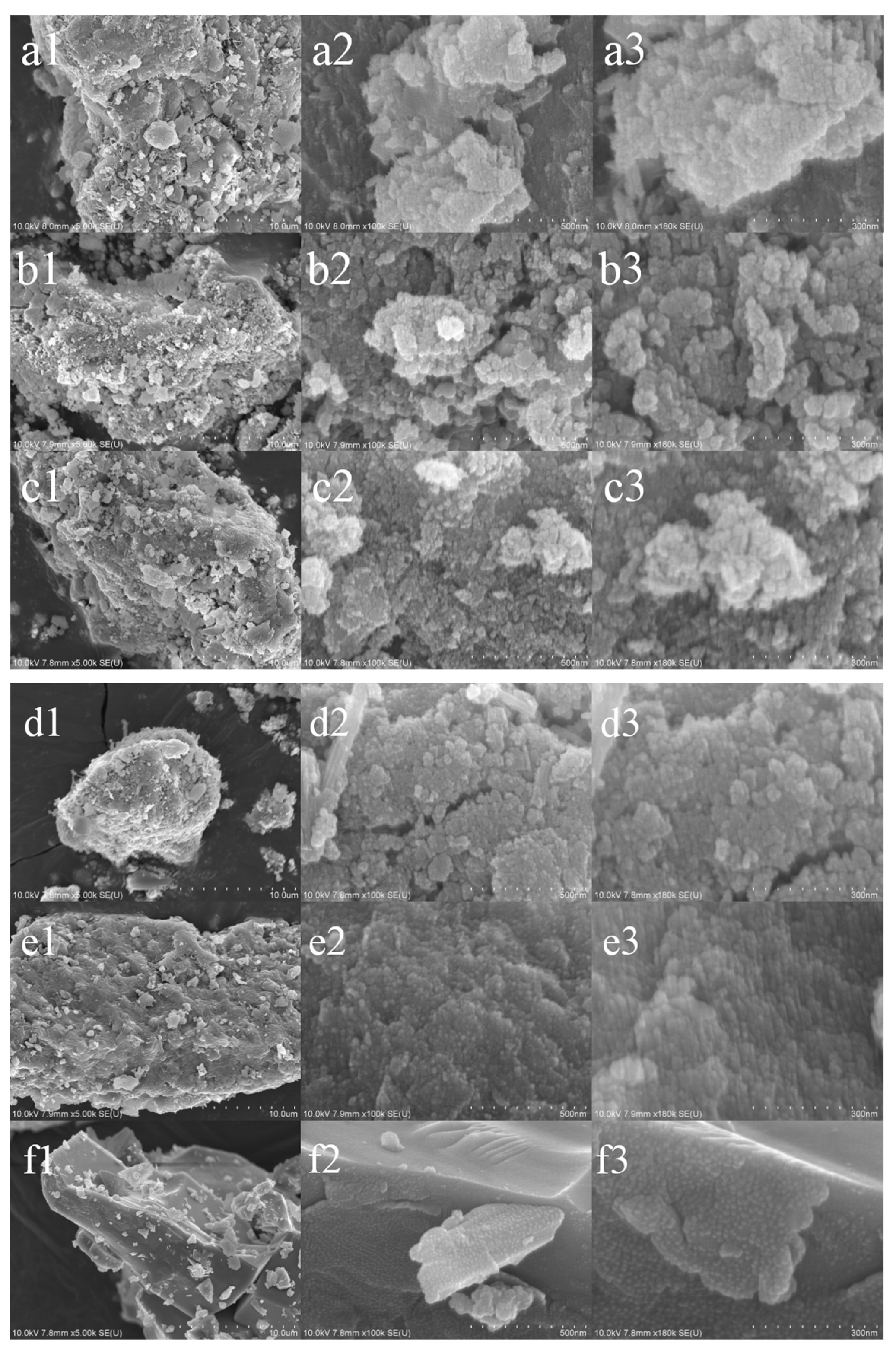
Figure 4, a series of CAT samples accidentally deactivated were evaluated. We carefully selected samples from several large scale Coal-to-Methanol/Liquid oil/Hydrocarbons industrial plants to make sure they are referential. Except one sample deactivated by caking (~45 mol% CO conversion at 450 °C), most of them were not completely deactivated but quite close to the status of CAT 3–4 years served. Their morphology was presented by scanning electron microscopy (SEM) as shown in
Figure 5.
Caking is an early-stage deactivation of alumina-based catalysts serving for years due to which the catalyst particles became loose (not very obviously), further compressed or agglomerated. A general reason for caking could be the high-pressure hydrothermal working conditions, e.g., 3 Mpa for SWGS. As caking is a more ‘physical’ property change, no obvious morphological difference was found between CATs used for 4 years (
Figure 5a), CATs used for 3 years (
Figure 5b), CATs deactivated by caking 1 (
Figure 5c) and CATs deactivated by caking 2 (
Figure 5d).
Water soaking accidently occurs between the WGS plant operating cycles. There are various reasons for the local enrichment of water/steam in a WGS plant, which leads to the catalyst surface being oversaturated with H
2O which could be another important reason for catalyst caking. From SEM results (
Figure 5e), the water-soaked CATs showed very similar morphology as compared to CATs served for years or caked, with only a small difference on the catalyst surface (more obviously seen in
Figure 5e3, the surface of CATs presented special ‘washing’ appearance). CATs deactivated by
sintering exhibited the worst catalytic performance (
Figure 4k) in terms of the lowest CO conversions at the selected three temperatures, indicating the most severe damage of catalytic sites. This is more evidenced by the SEM results (
Figure 5f); the apparent crystallization reflected in the picture brought in the dramatic and irreversible reducing of catalyst surface and active sites. It should be mentioned that there were in fact very unusual catalyst deactivations by ‘poisoning’ in which case poisonous elements (e.g., As and Cl), even in very small amounts, deposited over the catalyst surface (
Figure 6). By far, no strong links were found between the cause of WGS deactivation and the above catalyst poisoning. Such accident rarely occurred and could be attributed to the unsuccessful coal preparation before gasification.
More information about the surficial elemental compositions of different samples are listed in
Table 2 and
Table 3. Trends have been found for the 1–4 years served CATs. Fresh (as-prepared) CAT possessed the highest Mo level and Al level, which fell gradually as the serving years increased. The 1 year served CAT became sulfurized, then the sulfur level decreased at a faster rate than Mo and Al. As more Mo elements were continuously lost from the catalyst surface, the surface level (concentration) of Co elements accordingly increased implying they were comparably more stable in the LSGRT SWGS process. No Cl or As was observed on the surface of as-prepared CAT, but their concentrations went up gradually with the time on stream of WGS increasing. For the industrial SWGS process, it was difficult to completely avoid the accumulation of unexpected poisoning elements over the catalyst surface especially during a long-time plant running.
CaO was introduced in the preparation of CAT as a common method to improve the catalyst mechanical strength. As shown in
Table 2, even in a very small amount, Ca content over the catalyst surface fell gradually with time on stream extending. However, as shown in
Table 3, the sintered CAT and caked CATs exhibited much higher Ca levels than all other samples. The accumulation of Ca over CAT surface might be a direct reason of catalyst particle growth and aggregation, which led to the final deactivation by caking [
12,
26,
27]. In some cases, the slow caking of catalyst particles could be accelerated by high temperatures and finally evolved to the sintering deactivation: 1) The WGS reaction is exothermic, more exothermic is due to higher accompanied methanation side reaction which might occur at aggregated catalyst particles causing locally over-heated sites (hot spot). 2) The local high temperature further accelerates the metal particle growth and finally the aggregation (sintering). 3) The observed high Ca levels of caked and sintered samples supported the above explanations.
All unloaded CATs showed different levels of carbon deposition over the catalyst surfaces as a straightforward evidence of coking deactivation. However, even the sintered CAT and caked CATs have more cokes; coke formation was still not regarded as the main reason for WGS deactivation; a possible reason could be the H2 generated in the WGS reaction suppressed the development of catalyst coking.
Crystal structures of different samples were analyzed with X-ray diffraction (XRD) as shown in
Figure 7,
Figure 8 and
Figure 9. The sharper diffraction peaks of γ-Al
2O
3 in
Figure 7 indicate all CATs served for different years have developed further crystalized alumina structures as compared with fresh CAT, which is a common result for alumina supported catalysts long-term served with steam. Diffraction (a peak at ~61°) from the 008 plane of crystal MoS
2 was clearly observed on the 1 year served CAT, as an early sign of the irreversible loss of mono-layer dispersed MoS
2 which is the active sites for catalytic CO conversion [
28]. Diffractions from the 105 plane (a peak at ~50°) and 002 plane (a peak at ~14°) of crystal MoS
2 were continuously found on CATs served for 3 years and 4 years [
28]. The above results reflected an evolution of the MoS
2 phase supported on CAT when served in the industrial WGS plant under a lean steam/gas ratio, which is supposed to start from a mono-layer distribution and gradually develop into a complex crystal structure. Crystal phases of CaMoO
4 and MgAl
2O
4 were also found to be present on all served CATs indicating an effective alkali modification.
By comparison (
Figure 8), the crystallinity of γ-Al
2O
3 was noted to be less developed on Cl and As poisoned, caked and steam-soaked CATs, which is more similar to the as-prepared CAT. These observations match the fact that CATs in
Figure 8 were not used for a long time due to the deactivation. On the other hand, these XRD observations also indicate caking, as the early stage of alumina supported catalyst blocking or sintering, did not show apparent impact on crystallization. Besides, crystal phases of boehmite (precursor of alumina support) were noted to be formed in the caked and Cl poisoned CATs all pointing to an undesired catalyst structure damage.
In operating catalyst beds both sintering and caking could lead to block formation or aggregation of alumina supported catalyst. However, as seen in our results (
Figure 9), for CATs served in LSGRT SWGS, only sintering leads to very distinguished and complicated crystalline structures. This is further supported by our SEM images (
Figure 5f) since the crystallization of sintered CATs is so apparent and uncontested. In
Figure 8 we also noted the formation of crystallized MoS
2 on the caked CAT sample (
Figure 8d, caking 2), which implies that caking might be another reason leading to the loss of mono layered MoS
2 and, therefore, the dramatic reduction of catalytic sites for SWGS.
For further analyses, Raman spectroscopy (
Figure 10) is employed to draw the surficial properties of different CATs. MoO
3 species (Raman shifts at ~320, ~910 and 1050 cm
−1) are only observed on the as-prepared (un-sulfurized) CAT. All served CATs have formed MoS
2 species on their surface as clearly evidenced by the featured Raman shifts at ~380 and ~410 cm
−1, respectively. The MoS
2 signals gradually drop as the serving time of CAT increases. Both the loss of sulfur contents and the MoS
2 crystallization could lead to a reduced MoS
2 catalyst surface dispersion in a long term SWGS process, which can be reflected by the gradually weakened MoS
2 Raman signals.
Caked, Cl-poisoned, As-poisoned CATs also exhibit clear MoS2 signals in a strong contrast to the sintered CAT which shows only very faint MoS2 Raman bands. For the sintered CAT, a group of unidentified Raman shifts between 800 and 950 cm−1 are observed possibly attributed to the complex interactions between catalyst surface Mo species. Raman shifts between 140 and 150 cm−1 only present in the spectra of as-prepared CAT, 4 years served CAT, and those accidentally deactivated CATs (except sintered CAT). A possible reason could be the variational interactions between the catalyst surface Mo species and support alumina; on the other hand, these signals might be part of the background when there is very weak MoS2 signal. Notably, Cl-poisoned, As-poisoned and water-soaked CATs also exhibited Raman shift of MoO3 at ~1050cm−1. It is assumed that for these CATs, the sulfurization of MoO3 was unpredictably disturbed.
Carbon bands (the D peak around 1350 cm
−1 and the G peak around 1580–1600 cm
−1) are also clearly detected by Laser Raman for the caked CAT, water-soaked CAT, sintered CAT and served CATs (
Figure 10 k–q). The D/G ratio of carbonaceous species was calculated for each sample to describe the extent of carbon formation [
29,
30]. The D/G ratio lies between 0.6 and 0.7 for CATs served for 1–3 years indicating a comparably uniform carbonaceous distribution on the catalyst surface. The 4 years served CAT possesses more diamondlike (DLC) carbons of SP
3 bonding which also implies that more hydrogen contents could exist in the deposited carbon compounds. Unlike carbon deposition obtained in a zeolite catalyzed acidic reaction, where the catalyst surface carbonaceous species are normally deeply dehydrogenated, the WGS reaction generates rich amounts of H
2 with steam which might possess an inverse role to hydrogenate the cokes. The D/G ratio of accidentally deactivated CATs varies in the range of 0.47–1.59; the exact reason may require a future investigation with the help of catalyst accidental deactivation simulation in laboratory conditions. Infrared spectroscopy was employed as a complement to the above Raman studies where comparisons were made with the previous IR studies on supported MoS
2 catalysts or others [
31,
32]
. As seen in
Figure 11, the as-prepared CAT without sulfur presented apparently divergent spectra in a stark contrast to the served, sulfurized CATs; for this sample (
Figure 11a) IR bands only appeared at 1600, 1380, 1280 and 1000 cm
−1. The above bands (IR peaks) became eroded (1380, 1280 and 1000cm
−1) or slightly shifted (1600 cm
−1) in the spectra of served CATs, as a good sign of sulfurization. Meanwhile, new bands at 1450, 1100 (there was even a small peak at 1050 cm
−1 in the spectra of CAT served 1 year which was ‘just sulfurized’ compared with the other 3 served CATs) and 890 cm
−1 appeared; the first two bands were so strong in the spectra that could be a most straightforward evidence showing the occurrence of successful sulfurization. As the serving years of CAT increased (
Figure 11b–e), the bands at 1450 and 1100 cm
−1 became gradually weakened with the WGS catalytic ability accordingly lowered; the 1450 cm
−1 band completely disappeared in the spectra of 4 years served CAT which was the most severely served CAT.
In the spectra of accidently deactivated CATs, 1450 and 890 cm
−1 (there was a shift to 840 cm
−1 in the spectra of sintered CATs) bands were still missing; however, the band at 1100 cm
−1 was clearly shown despite that signals were much weaker for the As-poisoned CAT (
Figure 12f).
Despite the poor resolution in coke analysis, for each sample attempts were also made to capture the possible IR bands of carbonaceous compounds deposited. However, in the commonly used coke domains both aromatic CH stretching modes (2800–3200 cm
−1) and paraffinic carbon CH stretching modes (3000–3200 cm
−1) were not confidentially detected, whereas the observed bands at 2850, 2925, 2960 and 3080 cm
−1 are possibly attributed to the catalyst support frameworks [
30].
The above IR discussions indicated that CATs in a good sulfurized condition mainly possessed two bands at 1450 and 1100 cm−1, respectively. Both bands might be responsible for the effective sulfur tolerant WGS. However, only the change of 1450 cm−1 band was noted more sensitive for those deactivated CATs, and therefore, it is more important to assess the remaining catalytic properties. Notably, this new finding was not reported in the previous studies of high steam/gas ratio sulfur tolerant WGS. Compared with the IR results, although more intensive in signals, Raman spectra only indicated an overall reduction of catalyst surface MoS2 species on the deactivated CATs (Raman shifts at ~380 and ~410 cm−1).

 ,
, 


