Hardening and Creep of Ion Irradiated CLAM Steel by Nanoindentation

1
State Key Laboratory for Turbulence and Complex System, Department of Mechanics and Engineering Science, BIC-ESAT, College of Engineering, Peking University, Beijing 100871, China
2
CAPT, HEDPS and IFSA, Collaborative Innovation Center of MoE, Peking University, Beijing 100871, China
*
Author to whom correspondence should be addressed.
Crystals 2020, 10(1), 44; https://0-doi-org.brum.beds.ac.uk/10.3390/cryst10010044
Submission received: 1 December 2019
/
Revised: 6 January 2020
/
Accepted: 13 January 2020
/
Published: 17 January 2020
(This article belongs to the Special Issue Indentation Testing for Materials Characterization of Crystalline Solids)
Abstract
:Ion irradiation, combined with nanoindentation, has long been recognized as an effective way to study effects of irradiation on the mechanical properties of metallic materials. In this research, hardening and creep of ion irradiated Chinese low activation martensitic (CLAM) steel are investigated by nanoindentation. Firstly, it is demonstrated that ion irradiation results in the increase of hardness, because irradiation-induced defects impede the glide of dislocations. Secondly, the unirradiated CLAM steel shows indentation creep size effect (ICSE) that the indentation creep strain decreases with the applied load, and ICSE is found to be associated with the variations of geometrical necessary dislocations (GNDs) density. However, ion irradiation results in the alleviation of ICSE due to the irradiation hardening. Thirdly, ion irradiation accelerates nanoindentation creep due to the large numbers of irradiation-induced vacancies whose diffusion controls creep deformation. Meanwhile, owing to the annihilation of vacancies, ion irradiation has a significant influence on the primary creep while only negligible influence has been observed for the steady-state creep.
1. Introduction
In the environment of fission/fusion reactors, metallic materials suffer from the bombardment of high energy particles which results in the formation of irradiation-induced defects, such as interstitials, vacancies, dislocation loops, stacking fault tetrahedra (SFTs), etc. [1,2,3]. The mechanical properties of metallic materials could be dramatically degraded by these defects, which is termed as the irradiation effects on mechanical properties including irradiation hardening, embrittlement, creep, and so on [4,5,6]. Hence, a deep understanding of irradiation effects is vital to the development of advanced structural materials for nuclear reactors. As opposed to extremely costly, lengthy, and complicated neutron irradiation, ion irradiation has been widely adopted due to its low costs, short irradiation times, and controllable irradiation conditions [7,8]. However, ion irradiation does have some drawbacks, such as limited penetration depth (several micrometers), and thus making it quite difficult to characterize mechanical properties of ion irradiated materials through conventional mechanical tests [9,10,11].
The fact that ion irradiation influences only a thin surface layer makes ion irradiated samples suitable for nanoindentation tests [12]. Depth-dependent hardness can be directly attained through Continuous Stiffness Measurement [13]. In recent years, a large number of nanoindentation tests have been conducted to investigate the irradiation hardening of metallic materials [9,10,14,15,16,17,18,19,20,21,22]. Meanwhile, several methods have been developed to obtain nanoindentation creep behavior, including constant rate of loading method [23], constant depth method [24], constant strain rate method [25], constant load method [26], and rate jump method [27]. Constant load method is the most widely used method due to the simple measurement and rapid data collection. With the constant load method, much research has been done to study the creep deformation of thin films [28,29,30,31,32,33,34,35,36,37,38]. Specifically, Huang et al. [38] demonstrated the feasibility of a high temperature nanoindentation creep study on ion irradiated oxide dispersion strengthened alloy. In short, these studies confirm that nanoindentation is an effective method for characterizing hardness and creep behavior of ion irradiated specimens.
Chinese low activation martensitic steel is a primary candidate structural material for the future fusion reactors due to its superior swelling resistance and thermos-mechanical properties. During the past decade, detailed studies have been conducted about the microstructure and mechanical properties of Chinese low activation martensitic (CLAM) steel before and after irradiation [17,18,19,20,21,39,40,41,42,43,44,45,46,47,48]. However, the creep behavior of irradiated CLAM steel has not been studied so far. In the present research, ion irradiation, combined with nanoindentation, is utilized to investigate the irradiation hardening and creep of CLAM steel. We seek to provide a comprehensive description of the nanoindentation hardness and creep behavior for CLAM steel before and after ion irradiation, and analyze the underlying mechanisms.
2. Materials and Methods
2.1. Specimen Preparation
The sample of CLAM steel (Heat 1506) [49] was provided by the FDS (Fusion Design Study) team in the Institute of Nuclear Energy Safety Technology, Chinese Academy of Sciences (Hefei, Anhui, China). The heat treatment consisted of quenching at 1273 K for 40 min followed by water cooling, and tempering at 1013 K for 90 min followed by air cooling [49]. The 6 mm × 6 mm × 2 mm specimens were fabricated through line cutting. The top surfaces were mechanically grinded and polished with a final step of 0.05 μm colloidal silica. Finally, the specimens were electrochemically polished with a polishing solution of 10% HClO4 + 90% C2H5OH at room temperature and 24 V to remove stressed layers caused by mechanical grinding and polishing from the surfaces.
To characterize the lath martensitic structure of CLAM steel, electron backscatter diffraction (EBSD) mapping was performed on the electrochemically polished surface of unirradiated specimen in a Quanta 650 FEG microscope (FEI Company, Hillsboro, OR, USA) equipped with an EBSD detector (Oxford Instrument plc, Abingdon, Oxon, UK) operating at a voltage of 20 kV and a step size of 0.22 μm.
2.2. Ion Irradiation
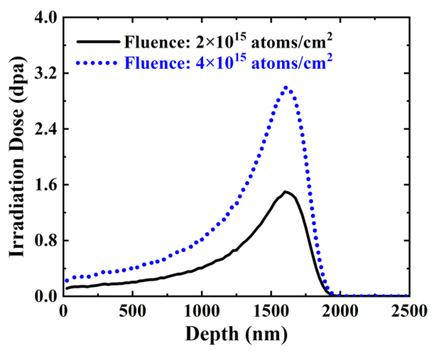
The specimens were irradiated at 393 ± 15 K using 6 MeV Si3+ via a 2 × 1.7 MeV tandem accelerator facility in Laboratory of Heavy Ion Physics, Peking University (Beijing, China). A heater with a thermal couple was used to control the irradiation temperature and another thermal couple was used to measure actual irradiation temperature. Figure 1 shows the irradiation dose–depth curves of CLAM steel specimens to a total fluence of 2 × 10¹⁵ atoms/cm2 and 4 × 10¹⁵ atoms/cm2. Irradiation dose profiles were calculated through SRIM 2008 output vacancy file using quick Kin-chin and Pease method [50,51]. The calculated maximum implant depth is about 2 μm.
As for the fluence of 2 × 10¹⁵ atoms/cm2, the peak irradiation dose is about 1.5 dpa (displacements per atom), while the average irradiation dose ranging from 0 nm to 1000 nm is about 0.2 dpa. As for the fluence of 4 × 10¹⁵ atoms/cm2, the peak irradiation dose is about 3.0 dpa, while the average irradiation dose ranging from 0 nm to 1000 nm is about 0.4 dpa. The detailed ion irradiation conditions for all specimens are given in Table 1.
2.3. Nanoindentation Tests
After ion irradiation, nanoindentation tests were performed at room temperature using Agilent Nano Indenter G200 (Agilent Technologies Inc., Santa Clara, CA, USA) with a Berkovich indentation tip. The area function of the indenter was calibrated through nanoindentation data obtained from fused silica.
The Continuous Stiffness Measurement [13] was used to characterize hardness–depth curves continuously up to the depth of 2000 nm. The strain rate was set to be 0.05 s−1. Before each hardness test, the indenter was set to wait until the initial thermal drift was below 0.5 nm/s [52,53]. For each specimen, five indents were tested with a spacing of 60 μm to avoid the interactions of their generated stress fields.
Nanoindentation creep tests were conducted via the constant load method. In all cases, the loading rate was set to reach the peak load in 15 s, and subsequently, the peak load was maintained for 30 s. The unirradiated specimen was tested with peak loads of 2 mN, 8 mN, 15 mN, 20 mN, and 150 mN. The 6 MeV Si3+ irradiated specimens were tested with peak loads of 2 mN, 8 mN, 15 mN, and 20 mN. The indenter load and depth were recorded continuously with time. Before each creep test, the indenter was set to wait until the initial thermal drift was below 0.05 nm/s. For each specimen, the tests were repeated ten times under the same conditions with a spacing of 60 μm to avoid the interactions of their generated stress field.
For all measurements, indentation depth was corrected by actual thermal drift which was measured through a 60 s dwell period at 90% of the unloading stage. The results of these five or ten indents were averaged to reduce the noise of hardness and creep results.
3. Results
3.1. Microstructure Analysis
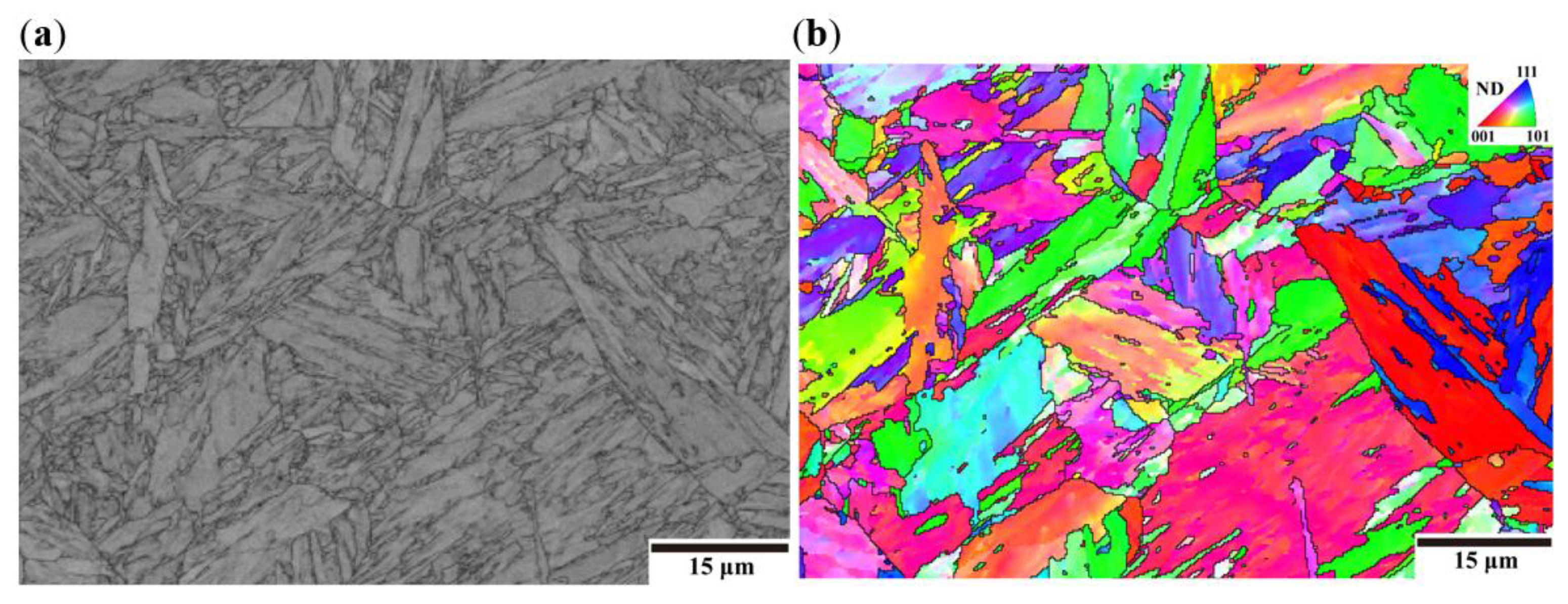
Figure 2a shows an image quality (IQ) map and Figure 2b shows an inverse pole figure (IPF) color map of the unirradiated CLAM steel obtained from the FE-SEM/EBSD measurements. The qualities of Kikuchi lines for each measurement are reflected through the IQ map. The low image quality corresponds to the dark gray-scale level at grain boundaries. It clearly reveals a typical lath martensitic structure, such as laths, blocks, and packets in a prior austenite grain as Kitahara et al. have shown [54]. The colors in Figure 2b represent the crystallographic orientation normal to the observed plane, as shown by the stereographic triangle in the inset. The boundaries in Figure 2b are drawn for misorientation angles between adjacent points greater than 15°, and the equivalent grain size calculated through the HKL channel 5 software (Oxford Instruments plc, Abingdon, Oxon, UK) is 1.9 μm, which is similar to the previous result of 0.20 wt.% C martensitic steel (2.1 μm) [54].
3.2. Nanoindentation Hardness
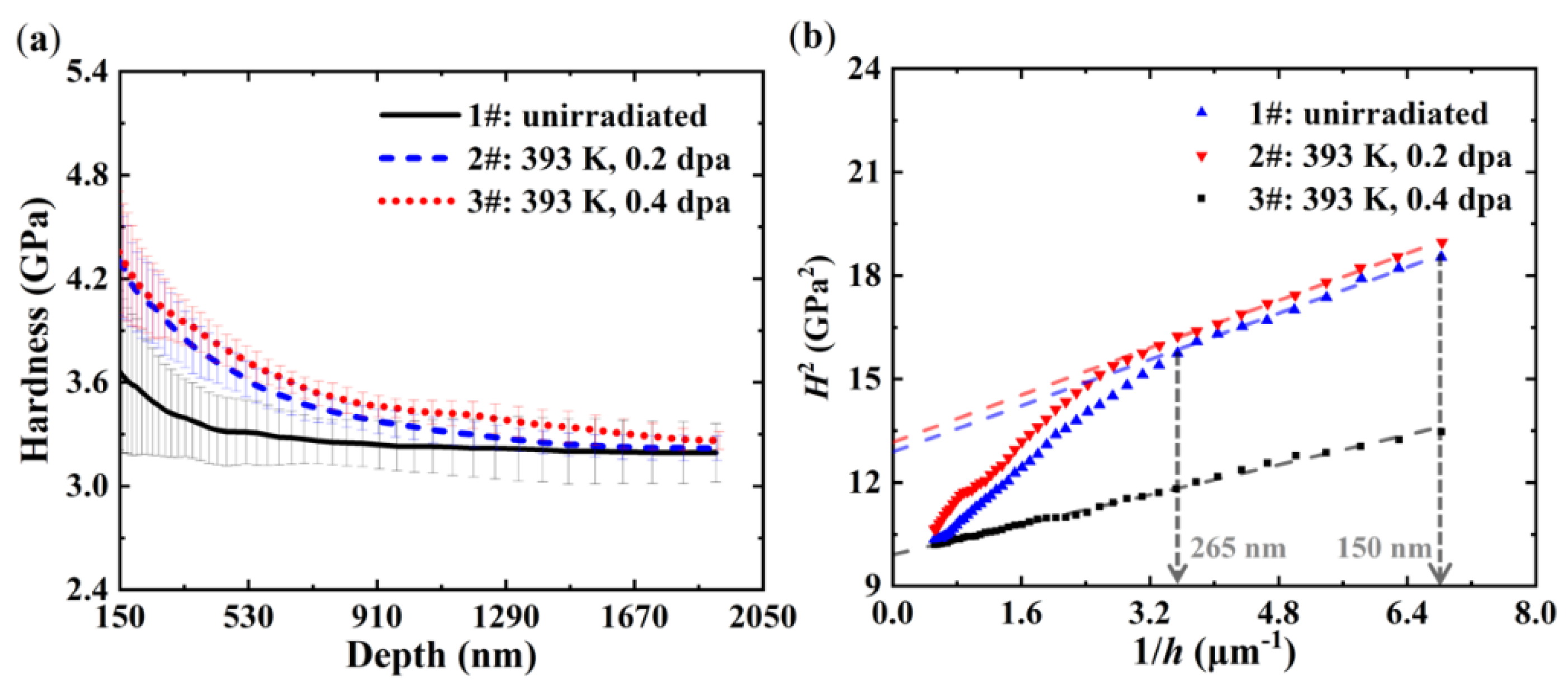
Nanoindentation hardness tests have been performed on both the unirradiated and 6 MeV Si3+ irradiated CLAM steel specimens. The actual thermal drift for hardness tests is ~0.1 nm/s. Figure 3a shows the hardness–depth curves of all specimens, where only the hardness at depth greater than 150 nm is presented due to the uncertainties from surface roughness [55], blunt tip on a sharp indenter [56], and elastic deformation effects [57]. Each line is the average hardness over five indents, and the error bars present the standard deviations. The large error bars are mainly attributed to the hierarchical lath martensitic structure as shown in Figure 2 [58,59,60]. The hardness–depth curves in Figure 3a clearly show that the hardness decreases with depth, which is the so-called indentation size effect (ISE) attributed to the variations of geometrical necessary dislocations (GNDs) density under the indenter [61]. The plastic zone under the indenter is generally three to five times the indentation depth for metals [11]. In addition, Figure 3a shows that hardness for depth greater than 1500 nm converges to a similar value for both the unirradiated and irradiated specimens. This indirectly illustrates that the effect of microstructural change due to irradiation temperature of 393 ± 15 K on hardness could be neglected.
Figure 3b shows curves of H2 versus 1/h for average hardness of all specimens, where H represents the hardness and h is the indentation depth. On the one hand, the curve for the unirradiated specimen shows a good linearity, which can be well fitted by the Nix–Gao model [61]:
where H0 represents the hardness at infinite depth, which can be considered as the bulk hardness, and h* is a characteristic length.
On the other hand, the curves for the irradiated specimens are approximately bilinear. When the indentation depth is greater than ~265 nm, the plastic zone extends beyond the irradiated layer and the hardness is largely affected by the unirradiated substrate [21,22,57,62,63]. However, when the indentation depth is less than ~265 nm, the hardness is affected mainly by the irradiated layer and can be well fitted by the Nix–Gao model, as reported by Kasada et al. [64].
Table 2 lists the extrapolated bulk hardness H0 for all specimens, which clearly shows that the hardness increases after irradiation and the magnitude of irradiation hardening increases with the irradiation dose.
3.3. Nanoindentation Creep
To investigate nanoindentation creep behavior of the unirradiated and 6 MeV Si3+ irradiated CLAM steel, systematic nanoindentation creep tests have been conducted via the constant load method. The actual thermal drift for creep tests is ~0.01 nm/s, with the actual deviation in 30 s dwell time to be ~0.3 nm.
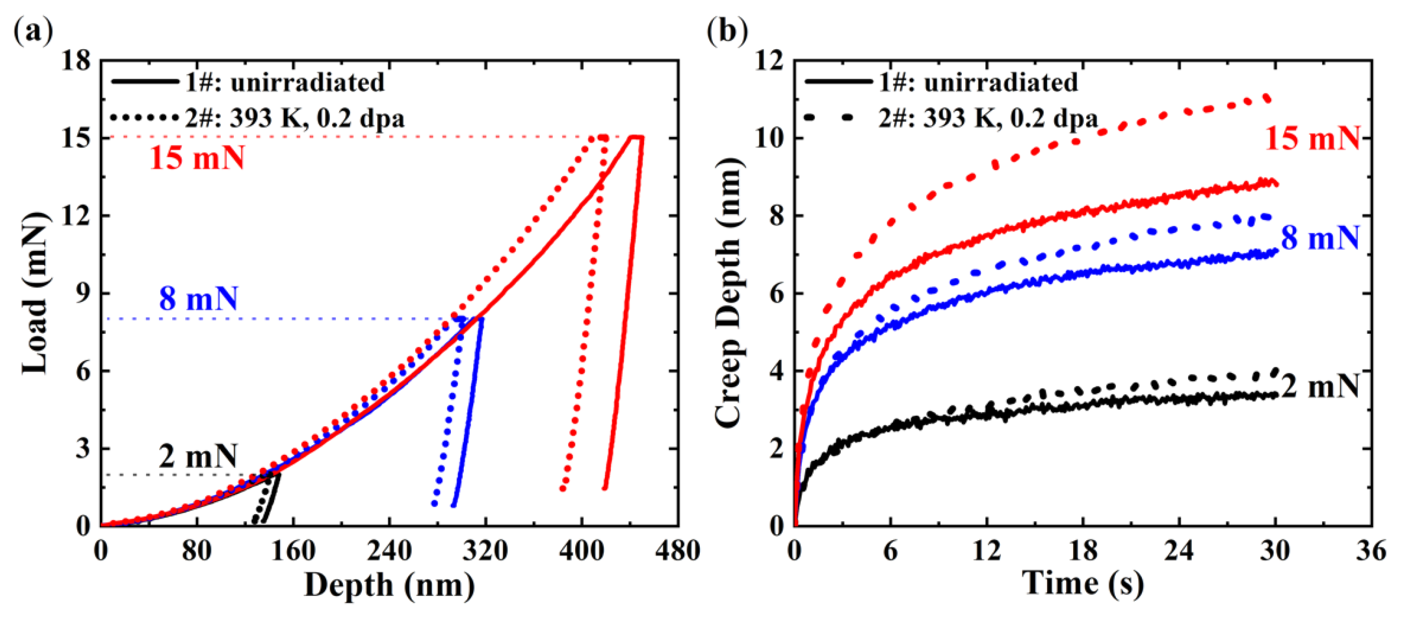
Figure 4a shows the typical average load–depth curves of 1# unirradiated and 2# Si3+ irradiated specimens obtained from nanoindentation creep tests performed at different peak loads of 2 mN, 8 mN, and 15 mN. It shows that a larger load is needed for 2# Si3+ irradiated specimen than 1# unirradiated specimen to reach the same depth, which is consistent with the larger hardness shown in Figure 3a. Figure 4b shows the corresponding average creep depth–time curves at the 30 s constant load stage shown in Figure 4a, with the starting time and depth of this stage to be set to zero for comparison. It clearly shows that under the same conditions, 2# Si3+ irradiated specimen sinks in deeper than 1# unirradiated specimen. Meanwhile, the creep depth increases with the applied load in both specimens before and after irradiation.
However, it is worth noting that nanoindentation creep behavior is an inherent property of CLAM steel, which should not be affected by load condition. Therefore, to exclude the influence of load condition, an indentation creep strain similar to the CIT shown in ISO standard [65] is defined to be creep depth divided by its current depth:
where is the current depth, is the starting depth of the constant load stage.
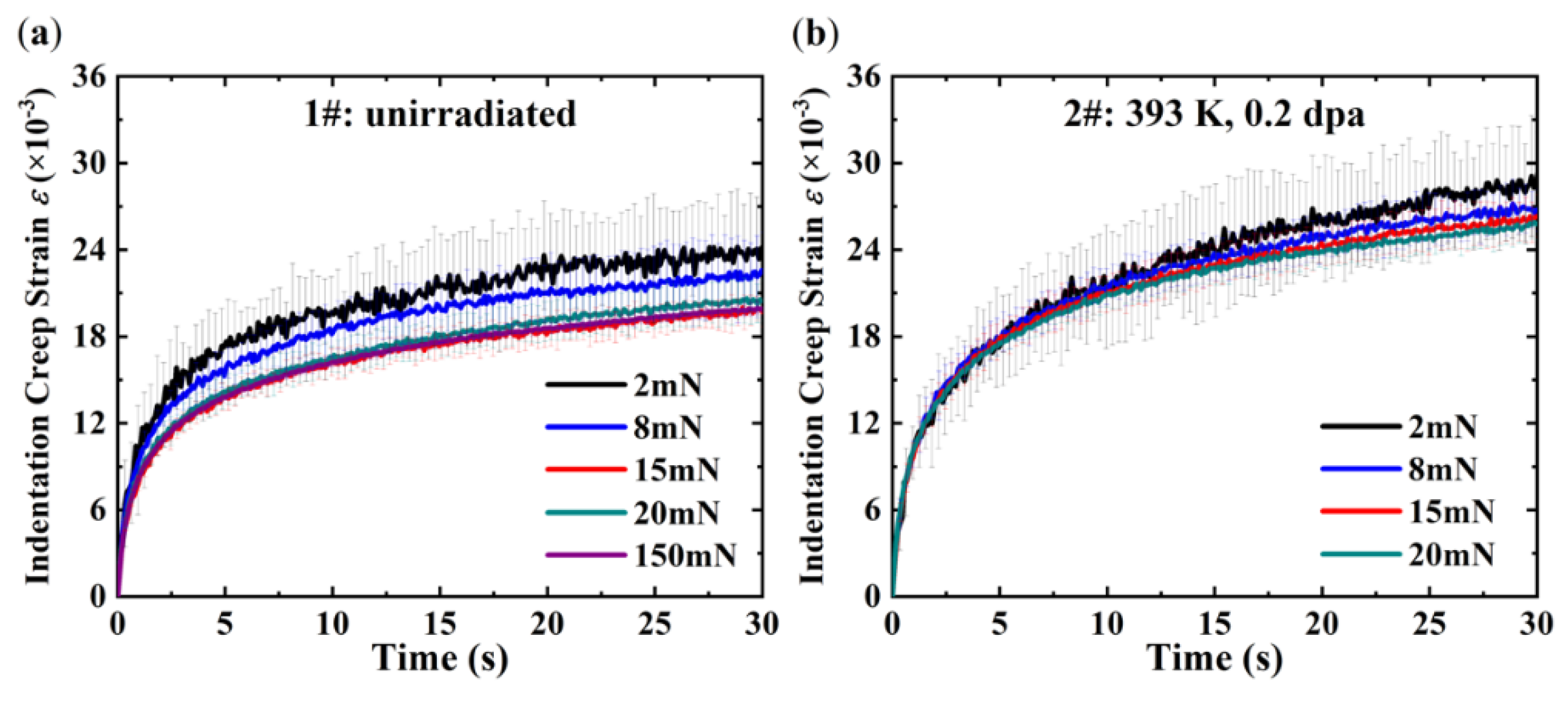
Figure 5a shows the indentation creep strain–time curves of 1# unirradiated specimen under different loads of 2 mN, 8 mN, 15 mN, 20 mN, and 150 mN. It can be found that the indentation creep strain decreases with the applied load when the load is less than 15 mN. Similar to the ISE, this phenomenon can be called as indentation creep size effect (ICSE), which will be discussed in Section 4.2. However, when the load is greater than 15 mN, the ICSE is negligible. Figure 5b shows the indentation creep strain–time curves of 2# Si3+ irradiated specimen under different loads of 2 mN, 8 mN, 15 mN, and 20 mN. It illustrates that the ICSE is alleviated after irradiation.
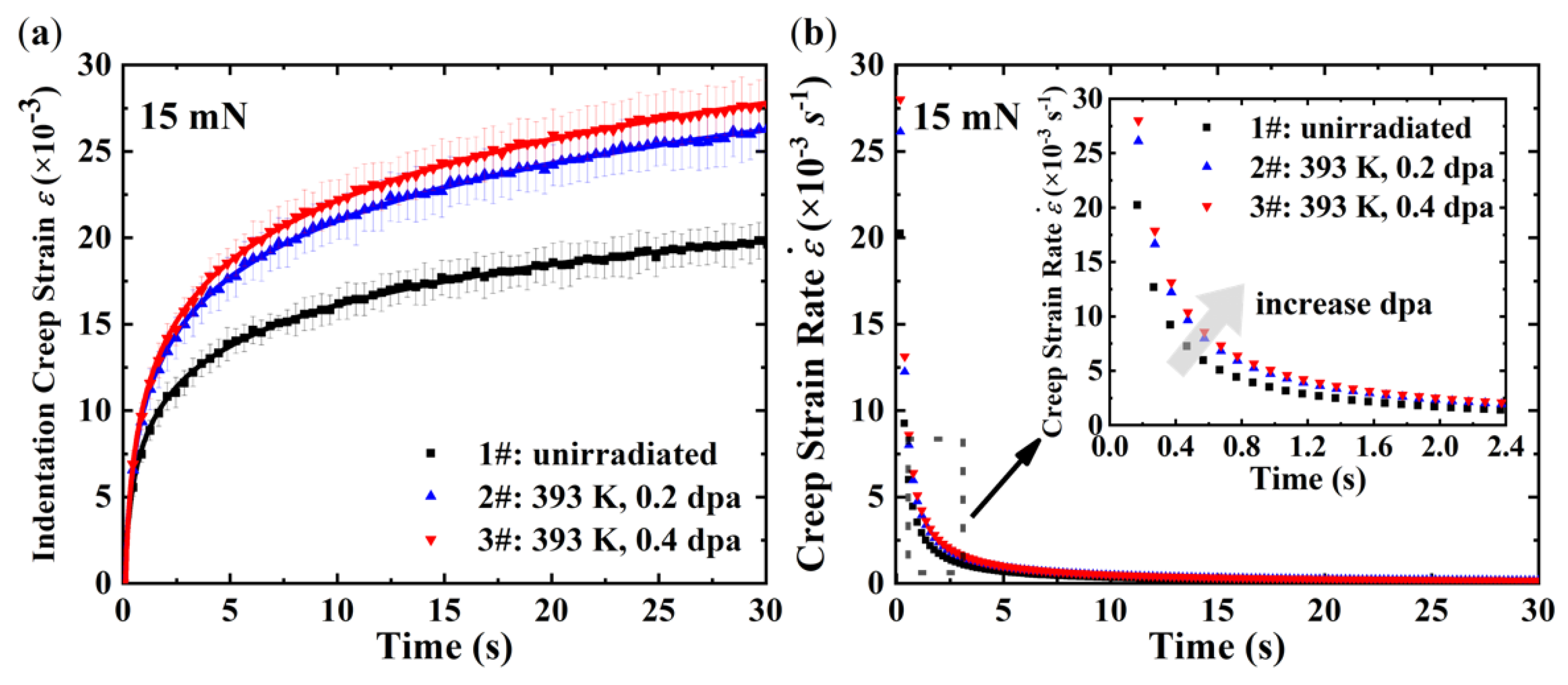
To further illustrate the effects of ion irradiation on nanoindentation creep behavior of CLAM steel, Figure 6a shows the indentation creep strain–time curves of all specimens under the load of 15 mN. It reveals that under the same conditions, the indentation creep strain of ion irradiated specimens is greater than the unirradiated specimen, which means the acceleration of nanoindentation creep after ion irradiation. Meanwhile, this acceleration is irradiation dose-dependent and a higher irradiation dose results in faster nanoindentation creep.
To investigate the effects of ion irradiation on the evolution of nanoindentation creep behavior, creep strain rate is calculated by fitting the indentation creep strain–time curves in Figure 6a. The fit curves are also shown in Figure 6a. The fitting protocol is found to produce very good fits to the experimental results. Figure 6b shows the calculated creep strain rate–time curves. It can be found that the creep strain rate of all specimens decreases with creep time and then reaches a steady state. Moreover, the magnified curves are shown in the insert of Figure 6b. It clearly reveals that the difference of the creep strain rate between specimens before and after irradiation decreases with creep time and finally disappears.
4. Discussion
4.1. Irradiation Hardening
Nanoindentation hardness results shown in Figure 3 and Table 2 demonstrate that ion irradiation can result in the increase of hardness and the magnitude of irradiation hardening increases with the irradiation dose. Many previous studies have been conducted on the irradiation hardening of different materials, including CLAM steel [9,10,14,15,16,17,18,19,20,21,22,64]. Generally, by neglecting the effects of implanted ions [64], it is attributed to the fact that irradiation-induced defects such as dislocation loops impede the glide of dislocations and can be quantified by the dispersed barrier model [5,19,21]:
where is the increased value of yield strength due to irradiation, is the number density of the irradiation-induced defects, is the average diameter of the irradiation-induced defects, is the shear modulus of the material, is the magnitude of Burgers vector, is the obstacle strength of irradiation-induced defects, and is the average Taylor factor of a polycrystal (for a BCC polycrystal ).
Since the nanoindentation hardness can be related to yield strength through the Tabor relation [66], one can express the increase of hardness induced by irradiation as:
Due to the fact that , , , and are material constants, the increase of hardness induced by irradiation is thus proportional to , i.e.,
4.2. Indentation Creep Size Effect
It is well-known that creep deformation is a diffusion-controlled process which consists of dislocation based diffusional creep and non-dislocation based diffusional creep [67]. Dislocation based diffusional creep assumes that the rate-controlled process is the diffusion of vacancies between dislocations [68], while non-dislocation based diffusional creep refers to the stress-directed flow of vacancies along grain boundaries [69]. In brief, creep deformation is controlled by the diffusion of vacancies [70].
Characteristic stress to describe stress field under the indenter during nanoindentation creep is taken as the applied load divided by the projected contact area , which is similar to the definition of hardness [71]:
As illustrated in Figure 5a, when the load is less than 15 mN, obvious ICSE that the indentation creep strain decreases with the applied load is observed in the unirradiated CLAM steel. However, when the load is greater than 15 mN, the ICSE is negligible. It can be found in Figure 3a that the ISE is only obvious when the indentation depth is less than ~450 nm, while Figure 4a shows that the starting depth of constant load stage in 1# unirradiated specimen under the load of 15 mN is about 440 nm. Therefore, when the load is less than 15 mN, characteristic stress decreases with the applied load due to the obvious ISE. Nevertheless, when the load is greater than 15 mN, the characteristic stress is almost the same under different loads because the ISE is unobvious as shown in Figure 3a. Meanwhile, considering creep mechanism, the ICSE could be explained by the increase of driving force for the diffusion of vacancies with characteristic stress. Hence, it is reasonable that the ICSE depends heavily on the characteristic stress which is determined by the applied load.
Figure 5b shows that the ICSE is alleviated after irradiation. As stated above, the ICSE in 1# unirradiated specimen is mainly caused by the decrease of characteristic stress with the applied load. However, in ion irradiated specimens, there are two main factors that influence the nanoindentation creep behavior, including the characteristic stress and the irradiation-induced vacancies. On the one hand, irradiation hardening results in the alleviation of the ISE, which is consistent with the fact that the hardness shows a slow change with the depth after irradiation, as shown in Figure 3a. Therefore, the characteristic stress of 2# Si3+ irradiated specimen shows less decrease with the applied load than 1# unirradiated specimen. On the other hand, the irradiation-induced vacancies are independent of the applied load so that they are likely to reduce the dependence of nanoindentation creep behavior on characteristic stress. However, this is just a speculation which needs more experimental verifications. Hence, considering these two factors, the indentation creep strain–time curves show reduced dependence on the applied load.
4.3. Irradiation Creep
To illustrate the effects of ion irradiation on nanoindentation creep behaviors, Figure 6 shows results under the same load of 15 mN to exclude the influence of the ICSE as much as possible. Figure 6a reveals the acceleration of nanoindentation creep after ion irradiation. Actually, high temperature nanoindentation creep study on the ion beam irradiated ODS alloy (PM2000) in Huang et al.’s research [38] has shown the similar tendency. However, the influence of high temperature on creep covers up the influence of ion irradiation, thus making the increase of creep depth due to irradiation difficult to be differentiated from the large errors. It is known that both high temperature and irradiation will induce large numbers of vacancies in metallic materials. The diffusion of these induced vacancies is promoted under the applied load. Therefore, ion irradiation plays a similar role as high temperature in accelerating creep. Meanwhile, Figure 6a also reveals that this acceleration is irradiation dose-dependent and a higher irradiation dose results in faster nanoindentation creep. This is probably because the concentration of the irradiation-induced vacancies increases with the irradiation dose, just as demonstrated by Zhu et al. [72].
Furthermore, Figure 6b illustrates the effects of ion irradiation on the creep strain rate. The creep strain rate shown in Figure 6b is consistent with conventional creep behavior of materials which can be divided into three stages: primary creep, steady-state creep, and tertiary creep [67]. The initial stage in Figure 6b (<~1 s), where the creep strain rate decreases rapidly, corresponds to primary creep when the material experiences hardening through changes in the dislocation substructure [67]. Then the creep strain rate reaches a steady state, which corresponds to steady-state creep when hardening is balanced by dynamic recovery (e.g., dislocation annihilation) [67]. Furthermore, the magnified curves shown in the insert of Figure 6b clearly reveal that the difference of the creep strain rate between specimens before and after irradiation decreases with creep time and finally disappears. This means that ion irradiation has a significant influence on the primary creep, while only negligible influence has been observed for the steady-state creep. This could be due to the fact that the plastic zone under the indenter is so small that the irradiation-induced vacancies in the plastic zone completely annihilate before steady-state creep [38]. However, further verifications are still required to completely clarify this phenomenon. Nevertheless, the observation of creep acceleration after irradiation is qualitatively consistent with that of conventional creep tests [4].
5. Conclusions
In summary, ion irradiation, combined with nanoindentation, is utilized to investigate the irradiation hardening and creep of Chinese low activation martensitic steel. The main conclusions are summarized as follows:
- (1)
- Ion irradiation results in the increase of hardness, because irradiation-induced defects impede the glide of dislocations;
- (2)
- The unirradiated CLAM steel shows indentation creep size effect (ICSE) that the indentation creep strain decreases with the applied load, and ICSE is found to be associated with the variations of geometrical necessary dislocations density. However, ion irradiation results in the alleviation of ICSE due to the irradiation hardening;
- (3)
- Ion irradiation results in the acceleration of nanoindentation creep due to the large numbers of irradiation-induced vacancies whose diffusion controls creep deformation. Meanwhile, owing to the annihilation of vacancies, ion irradiation has a significant influence on the primary creep while only negligible influence has been observed for the steady-state creep.
Author Contributions
Y.L. and W.L. conceived and designed the experiments; Y.L. performed the experiments; Y.L. analyzed the data; Y.L. wrote the paper; W.L., L.Y., L.C., H.S., and H.D. revised the paper; H.D. supervised the whole research. All authors have read and agreed to the published version of the manuscript.
Funding
This research was financially supported by the National Natural Science Foundation of China (Grant Nos. 11632001, 11521202, U1830121), and the Science Challenge Project, No. TZ2018001.
Acknowledgments
The authors would like to thank the FDS team in the Institute of Nuclear Energy Safety Technology, Chinese Academy of Sciences for providing the sample of CLAM steel (Heat 1506) and acknowledge the support by Jianming Xue from the State Key Laboratory of Nuclear Physics and Technology, Peking University, for the accelerator irradiation.
Conflicts of Interest
The authors declare no conflict of interest.
References
- Osetsky, Y.N.; Bacon, D.J.; Serra, A.; Singh, B.N.; Golubov, S.I. One-dimensional atomic transport by clusters of self-interstitial atoms in iron and copper. Philos. Mag. 2003, 83, 61–91. [Google Scholar] [CrossRef]
- Samaras, M.; Victoria, M. Modelling in nuclear energy environments. Mater. Today 2008, 11, 54–62. [Google Scholar] [CrossRef]
- Terentyev, D.; Vörtler, K.; Björkas, C.; Nordlund, K.; Malerba, L. Primary radiation damage in bcc Fe and Fe–Cr crystals containing dislocation loops. J. Nucl. Mater. 2011, 417, 1063–1066. [Google Scholar] [CrossRef]
- Kurata, Y.; Itabashi, Y.; Mimura, H.; Kikuchi, T.; Amezawa, H.; Shimakawa, S.; Tsuji, H.; Shindo, M. In-pile and post-irradiation creep of type 304 stainless steel under different neutron spectra. J. Nucl. Mater. 2000, 283–287, 386–390. [Google Scholar] [CrossRef]
- Was, G.S. Fundamentals of Radiation Materials Science: Metals and Alloys; Springer: New York, NY, USA, 2007; p. 711. [Google Scholar]
- Jiao, Z.; Was, G.S. The role of irradiated microstructure in the localized deformation of austenitic stainless steels. J. Nucl. Mater. 2010, 407, 34–43. [Google Scholar] [CrossRef]
- Was, G.S.; Busby, J.T.; Allen, T.; Kenik, E.A.; Jenssen, A.; Bruemmer, S.M.; Gan, J.; Edwards, A.D.; Scott, P.M.; Andresen, P.L. Emulation of neutron irradiation effects with protons: Validation of principle. J. Nucl. Mater. 2002, 300, 198–216. [Google Scholar] [CrossRef]
- Was, G.S.; Jiao, Z.; Getto, E.; Sun, K.; Monterrosa, A.M.; Maloy, S.A.; Anderoglu, O.; Sencer, B.H.; Hackett, M. Emulation of reactor irradiation damage using ion beams. Scr. Mater. 2014, 88, 33–36. [Google Scholar] [CrossRef]
- Heintze, C.; Bergner, F.; Akhmadaliev, S.; Altstadt, E. Ion irradiation combined with nanoindentation as a screening test procedure for irradiation hardening. J. Nucl. Mater. 2016, 472, 196–205. [Google Scholar] [CrossRef]
- Hardie, C.D.; Roberts, S.G.; Bushby, A.J. Understanding the effects of ion irradiation using nanoindentation techniques. J. Nucl. Mater. 2015, 462, 391–401. [Google Scholar] [CrossRef]
- Hosemann, P.; Kiener, D.; Wang, Y.; Maloy, S.A. Issues to consider using nano indentation on shallow ion beam irradiated materials. J. Nucl. Mater. 2012, 425, 136–139. [Google Scholar] [CrossRef]
- Oliver, W.C.; Pharr, G.M. An improved technique for determining hardness and elastic modulus using load and displacement sensing indentation experiments. J. Mater. Res. 1992, 7, 1564–1583. [Google Scholar] [CrossRef]
- Li, X.; Bhushan, B. A review of nanoindentation continuous stiffness measurement technique and its applications. Mater. Charact. 2002, 48, 11–36. [Google Scholar] [CrossRef]
- Hosemann, P.; Vieh, C.; Greco, R.R.; Kabra, S.; Valdez, J.A.; Cappiello, M.J.; Maloy, S.A. Nanoindentation on ion irradiated steels. J. Nucl. Mater. 2009, 389, 239–247. [Google Scholar] [CrossRef]
- Yabuuchi, K.; Kuribayashi, Y.; Nogami, S.; Kasada, R.; Hasegawa, A. Evaluation of irradiation hardening of proton irradiated stainless steels by nanoindentation. J. Nucl. Mater. 2014, 446, 142–147. [Google Scholar] [CrossRef]
- Reichardt, A.; Lupinacci, A.; Frazer, D.; Bailey, N.; Vo, H.; Howard, C.; Jiao, Z.; Minor, A.M.; Chou, P.; Hosemann, P. Nanoindentation and in situ microcompression in different dose regimes of proton beam irradiated 304 SS. J. Nucl. Mater. 2017, 486, 323–331. [Google Scholar] [CrossRef] [Green Version]
- Chang, Y.; Zhang, J.; Li, X.; Guo, Q.; Wan, F.; Long, Y. Microstructure and nanoindentation of the CLAM steel with nanocrystalline grains under Xe irradiation. J. Nucl. Mater. 2014, 455, 624–629. [Google Scholar] [CrossRef]
- Jiang, S.; Peng, L.; Ge, H.; Huang, Q.; Xin, J.; Zhao, Z. He and H irradiation effects on the nanoindentation hardness of CLAM steel. J. Nucl. Mater. 2014, 455, 335–338. [Google Scholar] [CrossRef]
- Wei, Y.P.; Liu, P.P.; Zhu, Y.M.; Wang, Z.Q.; Wan, F.R.; Zhan, Q. Evaluation of irradiation hardening and microstructure evolution under the synergistic interaction of He and subsequent Fe ions irradiation in CLAM steel. J. Alloys Compd. 2016, 676, 481–488. [Google Scholar] [CrossRef] [Green Version]
- Li, Q.; Shen, Y.; Huang, X.; Xu, Z.; Zhu, J. Irradiation-induced hardening and softening of CLAM steel under Fe ion irradiation. Met. Mater. Int. 2017, 23, 1106–1111. [Google Scholar] [CrossRef]
- Fu, Z.Y.; Liu, P.P.; Wan, F.R.; Zhan, Q. Helium and hydrogen irradiation induced hardening in CLAM steel. Fusion Eng. Des. 2015, 91, 73–78. [Google Scholar] [CrossRef]
- Kasada, R.; Konishi, S.; Yabuuchi, K.; Nogami, S.; Ando, M.; Hamaguchi, D.; Tanigawa, H. Depth-dependent nanoindentation hardness of reduced-activation ferritic steels after MeV Fe-ion irradiation. Fusion Eng. Des. 2014, 89, 1637–1641. [Google Scholar] [CrossRef]
- Mayo, M.J.; Nix, W.D. A micro-indentation study of superplasticity in Pb, Sn, and Sn-38 wt% Pb. Acta Metall. 1988, 36, 2183–2192. [Google Scholar] [CrossRef]
- LaFontaine, W.R.; Yost, B.; Black, R.D.; Li, C.Y. Indentation load relaxation experiments with indentation depth in the submicron range. J. Mater. Res. 1990, 5, 2100–2106. [Google Scholar] [CrossRef]
- Lucas, B.N.; Oliver, W.C. Indentation power-law creep of high-purity indium. Metall. Mater. Trans. A 1999, 30, 601–610. [Google Scholar] [CrossRef]
- Mayo, M.J.; Siegel, R.W.; Narayanasamy, A.; Nix, W.D. Mechanical properties of nanophase TiO2 as determined by nanoindentation. J. Mater. Res. 1990, 5, 1073–1082. [Google Scholar] [CrossRef]
- Alkorta, J.; Martínez-Esnaola, J.M.; Gil Sevillano, J. Critical examination of strain-rate sensitivity measurement by nanoindentation methods: Application to severely deformed niobium. Acta Mater. 2008, 56, 884–893. [Google Scholar] [CrossRef]
- Ding, Z.Y.; Song, Y.X.; Ma, Y.; Huang, X.W.; Zhang, T.H. Nanoindentation investigation on the size-dependent creep behavior in a Zr-Cu-Ag-Al bulk metallic glass. Metals 2019, 9, 613. [Google Scholar] [CrossRef] [Green Version]
- Sun, W.; Jiang, Y.; Sun, G.; Hu, J.; Zhou, T.; Jiang, Z.; Lian, J. Nanoindentation creep behavior and its relation to activation volume and strain rate sensitivity of nanocrystalline Cu. Mater. Sci. Eng. A 2019, 751, 35–41. [Google Scholar] [CrossRef]
- Wang, C.L.; Lai, Y.H.; Huang, J.C.; Nieh, T.G. Creep of nanocrystalline nickel: A direct comparison between uniaxial and nanoindentation creep. Scr. Mater. 2010, 62, 175–178. [Google Scholar] [CrossRef]
- Marques, V.M.F.; Wunderle, B.; Johnston, C.; Grant, P.S. Nanomechanical characterization of Sn–Ag–Cu/Cu joints—Part 2: Nanoindentation creep and its relationship with uniaxial creep as a function of temperature. Acta Mater. 2013, 61, 2471–2480. [Google Scholar] [CrossRef]
- Phani, P.S.; Oliver, W.C. A direct comparison of high temperature nanoindentation creep and uniaxial creep measurements for commercial purity aluminum. Acta Mater. 2016, 111, 31–38. [Google Scholar] [CrossRef]
- Phani, P.S.; Oliver, W.C.; Pharr, G.M. On the measurement of power law creep parameters from instrumented indentation. JOM 2017, 69, 2229–2236. [Google Scholar] [CrossRef]
- Li, H.; Ngan, A.H.W. Size effects of nanoindentation creep. J. Mater. Res. 2004, 19, 513–522. [Google Scholar] [CrossRef]
- Ma, Z.S.; Long, S.G.; Zhou, Y.C.; Pan, Y. Indentation scale dependence of tip-in creep behavior in Ni thin films. Scr. Mater. 2008, 59, 195–198. [Google Scholar] [CrossRef]
- Cao, Z.; Li, P.; Lu, H.; Huang, Y.; Zhou, Y.; Meng, X. Indentation size effects on the creep behavior of nanocrystalline tetragonal Ta films. Scr. Mater. 2009, 60, 415–418. [Google Scholar] [CrossRef]
- Haghshenas, M.; Wang, Y.; Cheng, Y.T.; Gupta, M. Indentation-based rate-dependent plastic deformation of polycrystalline pure magnesium. Mater. Sci. Eng. A 2018, 716, 63–71. [Google Scholar] [CrossRef]
- Huang, Z.; Harris, A.; Maloy, S.A.; Hosemann, P. Nanoindentation creep study on an ion beam irradiated oxide dispersion strengthened alloy. J. Nucl. Mater. 2014, 451, 162–167. [Google Scholar] [CrossRef]
- Huang, Q.; Li, C.; Li, Y.; Chen, M.; Zhang, M.; Peng, L.; Zhu, Z.; Song, Y.; Gao, S. Progress in development of China Low Activation Martensitic steel for fusion application. J. Nucl. Mater. 2007, 367–370, 142–146. [Google Scholar] [CrossRef]
- Liu, S.; Huang, Q.; Peng, L.; Li, Y.; Li, C. Microstructure and its influence on mechanical properties of CLAM steel. Fusion Eng. Des. 2012, 87, 1628–1632. [Google Scholar] [CrossRef]
- Wang, W.T.; Guo, X.Z.; Huang, B.; Tao, J.; Li, H.G.; Pei, W.J. The flow behaviors of CLAM steel at high temperature. Mater. Sci. Eng. A 2014, 599, 134–140. [Google Scholar] [CrossRef]
- Zhong, B.; Huang, B.; Li, C.; Liu, S.; Xu, G.; Zhao, Y.; Huang, Q. Creep deformation and rupture behavior of CLAM steel at 823 K and 873 K. J. Nucl. Mater. 2014, 455, 640–644. [Google Scholar] [CrossRef]
- Zhao, Y.; Zhai, X.; Liu, S.; Li, C.; Huang, Q. High cycle fatigue properties of CLAM steel at 723K and 823K. Fusion Eng. Des. 2015, 100, 608–613. [Google Scholar] [CrossRef]
- Peng, L.; Ge, H.; Dai, Y.; Huang, Q.; Ye, M. Microstructure and microhardness of CLAM steel irradiated up to 20.8 dpa in STIP-V. J. Nucl. Mater. 2016, 468, 255–259. [Google Scholar] [CrossRef]
- Luppo, M.I.; Bailat, C.; Schäublin, R.; Victoria, M. Tensile properties and microstructure of 590 MeV proton-irradiated pure Fe and a Fe-Cr alloy. J. Nucl. Mater. 2000, 283–287, 483–487. [Google Scholar] [CrossRef]
- Peng, L.; Huang, Q.; Li, C.; Liu, S. Preliminary analysis of irradiation effects on CLAM after low dose neutron irradiation. J. Nucl. Mater. 2009, 386–388, 312–314. [Google Scholar] [CrossRef]
- Liu, P.P.; Zhao, M.Z.; Zhu, Y.M.; Bai, J.W.; Wan, F.R.; Zhan, Q. Effects of carbide precipitate on the mechanical properties and irradiation behavior of the low activation martensitic steel. J. Alloys Compd. 2013, 579, 599–605. [Google Scholar] [CrossRef]
- Huang, X.; Shen, Y.; Li, Q.; Xu, Z.; Zhu, J. Microstructural evolution of CLAM steel under 3.5 MeV Fe13+ ion irradiation. Fusion Eng. Des. 2016, 109–111, 1058–1066. [Google Scholar] [CrossRef]
- Zhao, Y.; Liang, M.; Zhang, Z.; Jiang, M.; Liu, S. Fracture toughness and fracture behavior of CLAM steel in the temperature range of 450 °C–550 °C. J. Nucl. Mater. 2018, 501, 200–207. [Google Scholar] [CrossRef]
- Norgett, M.I.; Robinson, M.T.; Torrens, I.M. A proposed method of calculating displacement dose rates. Nucl. Eng. Des. 1975, 33, 50–54. [Google Scholar] [CrossRef]
- Ziegler, J.F. SRIM-2008 Program. Available online: http://www.srim.org/ (accessed on 13 June 2019).
- Trivedi, R.; Cech, V. Mechanical properties of plasma polymer film evaluated by conventional and alternative nanoindentation techniques. Surf. Coat. Technol. 2010, 205, S286–S289. [Google Scholar] [CrossRef]
- Allison, P.G.; Weiss, C.A.; Moser, R.D.; Diaz, A.J.; Rivera, O.G.; Holton, S.S. Nanoindentation and SEM/EDX characterization of the geopolymer-to-steel interfacial transition zone for a reactive porcelain enamel coating. Compos. Part B Eng. 2015, 78, 131–137. [Google Scholar] [CrossRef]
- Kitahara, H.; Ueji, R.; Tsuji, N.; Minamino, Y. Crystallographic features of lath martensite in low-carbon steel. Acta Mater. 2006, 54, 1279–1288. [Google Scholar] [CrossRef]
- Kim, J.Y.; Lee, J.J.; Lee, Y.H.; Jang, J.; Kwon, D. Surface roughness effect in instrumented indentation: A simple contact depth model and its verification. J. Mater. Res. 2006, 21, 2975–2978. [Google Scholar] [CrossRef]
- Kim, J.Y.; Lee, B.W.; Read, D.T.; Kwon, D. Influence of tip bluntness on the size-dependent nanoindentation hardness. Scr. Mater. 2005, 52, 353–358. [Google Scholar] [CrossRef]
- Liu, W.; Chen, L.; Cheng, Y.; Yu, L.; Yi, X.; Gao, H.; Duan, H. Model of nanoindentation size effect incorporating the role of elastic deformation. J. Mech. Phys. Solids 2019, 126, 245–255. [Google Scholar] [CrossRef]
- Miura, T.; Fujii, K.; Fukuya, K.; Takashima, K. Influence of crystal orientation on hardness and nanoindentation deformation in ion-irradiated stainless steels. J. Nucl. Mater. 2011, 417, 984–987. [Google Scholar] [CrossRef]
- Hakamada, M.; Nakamoto, Y.; Matsumoto, H.; Iwasaki, H.; Chen, Y.; Kusuda, H.; Mabuchi, M. Relationship between hardness and grain size in electrodeposited copper films. Mater. Sci. Eng. A 2007, 457, 120–126. [Google Scholar] [CrossRef]
- Hayakawa, M.; Tomatsu, K.; Nakayama, E.; Okamura, K.; Yamamoto, M.; Shizawa, K. Evaluating microscopic hardness in ferritic steel based on crystallographic measurements via electron backscatter diffraction. Mater. Sci. Eng. A 2017, 700, 281–290. [Google Scholar] [CrossRef]
- Nix, W.D.; Gao, H.J. Indentation size effects in crystalline materials: A law for strain gradient plasticity. J. Mech. Phys. Solids 1998, 46, 411–425. [Google Scholar] [CrossRef]
- Xiao, X.; Chen, Q.; Yang, H.; Duan, H.; Qu, J. A mechanistic model for depth-dependent hardness of ion irradiated metals. J. Nucl. Mater. 2017, 485, 80–89. [Google Scholar] [CrossRef] [Green Version]
- Xu, C.; Zhang, L.; Qian, W.; Mei, J.; Liu, X. The studies of irradiation hardening of stainless steel reactor internals under proton and xenon irradiation. Nucl. Eng. Technol. 2016, 48, 758–764. [Google Scholar] [CrossRef] [Green Version]
- Kasada, R.; Takayama, Y.; Yabuuchi, K.; Kimura, A. A new approach to evaluate irradiation hardening of ion-irradiated ferritic alloys by nano-indentation techniques. Fusion Eng. Des. 2011, 86, 2658–2661. [Google Scholar] [CrossRef] [Green Version]
- International Standard ISO 14577-1. Metallic Materials–Instrumented Indentation Test for Hardness and Materials Parameters–Part 1: Test Method; ISO: Geneva, Switzerland, 2015. [Google Scholar]
- Tabor, D. A simple theory of static and dynamic hardness. Proc. R. Soc. A 1948, 192, 247–274. [Google Scholar]
- Kassner, M.E. Fundamentals of Creep in Metals and Alloys, 3rd ed.; Elservier: Amsterdam, The Netherlands, 2015; pp. 1–288. [Google Scholar]
- Weertman, J. Theory of steady-state creep based on dislocation climb. J. Appl. Phys. 1955, 26, 1213–1217. [Google Scholar] [CrossRef]
- Langdon, T.G. Creep at low stresses: An evaluation of diffusion creep and Harper–Dorn creep as viable creep mechanisms. Metall. Mater. Trans. A 2002, 33, 249–259. [Google Scholar] [CrossRef]
- Mehrer, H. Diffusion in Solids: Fundamentals, Methods, Materials, Diffusion-Controlled Processes; Springer: New York, NY, USA, 2007; p. 180. [Google Scholar]
- Goodall, R.; Clyne, T.W. A critical appraisal of the extraction of creep parameters from nanoindentation data obtained at room temperature. Acta Mater. 2006, 54, 5489–5499. [Google Scholar] [CrossRef]
- Zhu, H.; Wang, Z.; Gao, X.; Cui, M.; Li, B.; Sun, J.; Yao, C.; Wei, K.; Shen, T.; Pang, L.; et al. Positron annihilation Doppler broadening spectroscopy study on Fe-ion irradiated NHS steel. Nucl. Instrum. Methods Phys. Res. Sect. B 2015, 344, 5–10. [Google Scholar] [CrossRef]
Figure 1.
SRIM-calculated irradiation dose–depth curves of Chinese low activation martensitic (CLAM) steel specimens irradiated with 6 MeV Si3+ to a total fluence of 2 × 10¹⁵ atoms/cm2 and 4 × 10¹⁵ atoms/cm2.
Figure 1.
SRIM-calculated irradiation dose–depth curves of Chinese low activation martensitic (CLAM) steel specimens irradiated with 6 MeV Si3+ to a total fluence of 2 × 10¹⁵ atoms/cm2 and 4 × 10¹⁵ atoms/cm2.

Figure 2.
(a) Image quality map and (b) inverse pole figure color map of the unirradiated CLAM steel. Colors in (b) represent the crystallographic orientation normal to the observed plane as shown by the stereographic triangle. Black lines in (b) show the boundaries with misorientation angles greater than 15°.

Figure 3.
(a) The hardness–depth curves of the unirradiated and 6 MeV Si3+ irradiated specimens. (b) Curves of H2 versus 1/h for average hardness of the unirradiated and 6 MeV Si3+ irradiated specimens.
Figure 3.
(a) The hardness–depth curves of the unirradiated and 6 MeV Si3+ irradiated specimens. (b) Curves of H2 versus 1/h for average hardness of the unirradiated and 6 MeV Si3+ irradiated specimens.

Figure 4.
(a) The average load–depth curves of 1# unirradiated and 2# Si3+ irradiated specimens over 10 indents obtained from nanoindentation creep tests performed at different peak loads of 2 mN, 8 mN, and 15 mN. (b) Corresponding average creep depth–time curves over 10 indents at the 30 s constant load stage shown in (a).

Figure 5.
(a) The indentation creep strain–time curves of 1# unirradiated specimen under different loads of 2 mN, 8 mN, 15 mN, 20 mN, and 150 mN. (b) The indentation creep strain–time curves of 2# Si3+ irradiated specimen under different loads of 2 mN, 8 mN, 15 mN, and 20 mN.
Figure 5.
(a) The indentation creep strain–time curves of 1# unirradiated specimen under different loads of 2 mN, 8 mN, 15 mN, 20 mN, and 150 mN. (b) The indentation creep strain–time curves of 2# Si3+ irradiated specimen under different loads of 2 mN, 8 mN, 15 mN, and 20 mN.

Figure 6.
(a) The experimental and fitting indentation creep strain–time curves of 1# unirradiated, 2#, and 3# Si3+ irradiated specimens under the load of 15 mN. (b) Creep strain rate–time curves corresponding to (a).
Figure 6.
(a) The experimental and fitting indentation creep strain–time curves of 1# unirradiated, 2#, and 3# Si3+ irradiated specimens under the load of 15 mN. (b) Creep strain rate–time curves corresponding to (a).


Table 1.
Ion irradiation conditions for all specimens.
| Specimens | Ions | Energy (MeV) | Irradiation Temperature (K) | Irradiation Dose 1 (dpa) | Irradiation Time 2 (min) |
|---|---|---|---|---|---|
| 1# | —— | —— | room temperature | unirradiated | 0 |
| 2# | Si3+ | 6 | 393 ± 15 | 0.2 | 53 |
| 3# | Si3+ | 6 | 393 ± 15 | 0.4 | 155 |
1 Irradiation dose represents the average irradiation dose ranging from 0 nm to 1000 nm calculated through SRIM 2008. 2 Irradiation time is determined by the specimen size, fluence, and real-time beam intensity.
Table 2.
The H0 obtained from the Nix–Gao model.
| Specimens | Irradiation Dose (dpa) | H0 (GPa) |
|---|---|---|
| 1# | unirradiated | 3.15 |
| 2# | 0.2 | 3.59 |
| 3# | 0.4 | 3.63 |
© 2020 by the authors. Licensee MDPI, Basel, Switzerland. This article is an open access article distributed under the terms and conditions of the Creative Commons Attribution (CC BY) license (http://creativecommons.org/licenses/by/4.0/).
Share and Cite
MDPI and ACS Style
Liu, Y.; Liu, W.; Yu, L.; Chen, L.; Sui, H.; Duan, H. Hardening and Creep of Ion Irradiated CLAM Steel by Nanoindentation. Crystals 2020, 10, 44. https://0-doi-org.brum.beds.ac.uk/10.3390/cryst10010044
AMA Style
Liu Y, Liu W, Yu L, Chen L, Sui H, Duan H. Hardening and Creep of Ion Irradiated CLAM Steel by Nanoindentation. Crystals. 2020; 10(1):44. https://0-doi-org.brum.beds.ac.uk/10.3390/cryst10010044
Chicago/Turabian StyleLiu, Ying, Wenbin Liu, Long Yu, Lirong Chen, Haonan Sui, and Huiling Duan. 2020. "Hardening and Creep of Ion Irradiated CLAM Steel by Nanoindentation" Crystals 10, no. 1: 44. https://0-doi-org.brum.beds.ac.uk/10.3390/cryst10010044
Note that from the first issue of 2016, this journal uses article numbers instead of page numbers. See further details here.