1. Introduction
Recently, research into the application of liquid crystal displays (LCDs) in various fields, such as televisions, smartphones, laptops, cameras, and other equipment, has been actively conducted. Indeed, LCD technologies remain important because of their advantageous intermediate states between an isotropic liquid and a crystalline solid. These LCDs are driven by an applied voltage, and a transparent conductive substrate on which a metal oxide such as indium tin oxide (ITO) is deposited is commonly used as an electrode [
1,
2,
3,
4,
5,
6,
7,
8,
9]. Owing to its transparency and low resistance, ITO is applied not only to LCDs but also to many fields of displays, such as organic light-emitting diodes (OLEDs), pixel electrodes, and touch panel electrodes. However, ITO cannot be used when flexibility is required or when a low-temperature process is required. Specifically, ITO has issues related to high manufacturing costs, low flexibility, and the requirement for high-temperature processing due to vacuum evaporation and photolithography; moreover, it has limitations in electrode applications owing to its high brittleness [
10,
11,
12,
13,
14]. Furthermore, the ITO unit price is gradually rising due to the depletion of indium, and it is expected that the production of ITO thin films will become impossible in the future; the introduction of low-resistance transparent electrodes that can replace ITO is therefore a necessity [
15,
16,
17,
18].
Recently, studies have been actively conducted to achieve low resistance characteristics through the use of high-conductivity nanomaterials, with the aim of also securing flexibility [
19,
20,
21,
22]. In particular, nanotechnology based on silver nanowires (AgNWs) has been successfully applied to LCD devices [
20]. Although metals, which have the highest conductivity, are attracting attention as potential candidates, they exhibit a high reflection in the visible light region and are not transparent. However, if the use of a metal where then particle dimensions are particularly nanosized is considered, the transmittance requirements could be satisfied while maintaining high conductivity. Therefore, nanomaterials such as AgNWs are promising candidates for transparent electrodes in the LCD industry, and play a key role in realizing flexible LCDs.
In addition, in LCDs, the initial orientation of the liquid crystal molecules is a key factor in determining the device performance. Especially, vertical alignment of nematic liquid crystals (LCs) can provide a high contrast ratio, a wide viewing angle, and rapid LC switching time [
23,
24]. As a conventional alignment layer, polyimide (PI) is commonly employed in displays, since it uniformly aligns the LC molecules in the desired direction, in addition to increasing the pretilt angle and the alignment stability through molecular-level interactions between PI and the LCs [
25,
26,
27]. However, commercial PI alignment layer in LCDs commonly requires a high-temperature curing step for imidization of poly(amic acid)s, restricting the potential applicability to flexible LC displays.
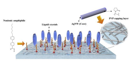
Thus, we herein report the facile and effective alignment method for nematic LCs using the self-assembled alignment layer of nonionic amphiphiles on silver nanowire electrodes. A transparent electrode based on silver nanowires was applied on glass substrate to replace ITO, and the polyvinylpyrrolidone (PVP) capping layer of silver nanowire networks was spontaneously bonded to the nonionic amphiphiles through polar interactions in the confined LC cell (
Figure 1). Due to the transparent nature of AgNWs, in addition to their high conductivity and flexibility, and their simple and low-cost production process, it is possible to create a nanostructured electrode using only a solution coating process without the requirement for a complex deposition process or photolithography. Furthermore, the self-constructed molecular layer of 4-(4-heptylphenyl)benzoic acids as nonionic amphiphiles on AgNWs electrodes served as a new vertical alignment layer to replace conventional PI. This amphiphilic material was mixed with LCs, and then injected into the AgNW-coated cell. The polar carboxyl group of nonionic amphiphiles can bind to polar PVP surface of AgNWs electrode in the LC medium, leading to the spontaneous formation of homeotropic molecular layer on AgNWs network. Moreover, the vertically oriented alkyl chains of self-assembled layer can induce vertical alignment of the LCs.
2. Materials and Methods
2.1. Synthesis of the Ag Nanowires
Polyvinylpyrrolidone (6 g, PVP, MW = 55,000, Sigma Aldrich, St. Louis, WI, USA) was added to glycerol (190 mL, ≥99.5%, Sigma Aldrich, St. Louis, WI, USA) in a 500 mL round-bottomed flask and dissolved by stirring at 80 °C. Upon the complete dissolution of PVP, the mixture was cooled to 25 °C. AgNO3 (1.58 g, Samchun chemicals, Pyeongtaek, Korea) was ground with a pestle and added to the prepared solution; the mixture was stirred to ensure the complete dissolution of the silver salt. Separately, NaCl (58.5 mg, Sigma Aldrich, St. Louis, WI, USA) was dissolved in deionized (DI) water (0.5 mL) in a 50 mL beaker, after which glycerol (10 mL) was added, and the resulting mixture was stirred for 5 min. This NaCl solution was then added to the Ag solution and slowly heated to 210 °C for 20 min under air using a heating mantle while stirring at 50 rpm using a glass rod. This process should be carried out over 10 steps, whereby the temperature is increased by 18 °C every 2 min (one step). After reaching the desired temperature of 210 °C and observing a number of color changes, the reaction was considered to have reached completion, and was cooled to 25 °C. After dividing the prepared solution into 10 conical tubes by 20 mL, deionized (DI) water was added in a 1:1 volume ratio, and the resulting mixture subjected to centrifugation at 8000 rpm for 10 min. After this time, the supernatant was removed from the settled precipitate, and the precipitate was washed three times with DI water with centrifugation to remove any remaining residue. The product was then transferred to a clean beaker, acetone (25 mL, 99.5%, Samchun pure chemical, Pyeongtaek, Korea) was added, and the precipitate was allowed to disperse for 30 s using a digital sonifier (digital sonifier 250, Branson, St. Louis, MO, USA). After allowing the precipitate to settle, the supernatant was removed, and this washing process was repeated a further three times to produce the desired AgNWs.
2.2. Fabrication of the Test LC Cell Containing the AgNW Electrodes and Nonionic Amphiphiles
The bare glass substrate was thoroughly cleaned as follows. After washing in acetone for 10 min under ultrasonication, the glass substrate was washed with isopropyl alcohol for 10 min, then with DI water for 10 min. After drying for 15 min on a hot plate at 100 °C, the cleaned substrate was surface-treated for 30 min with an ultraviolet (UV) ozone cleaner (UVC-30, Jaesung Engineering, Anyang, Korea) to create hydroxyl groups on the surface. This pretreated glass was used as both the upper and lower substrates. Suspensions of AgNWs in ethanol with 3, 5, and 7 mg/mL concentrations were spin-coated onto the substrate at 500 rpm for 30 s prior to annealing at 140 °C for 10 min to give AgNW electrodes on the substrate surface. The 4-(4-heptylphenyl)benzoic acid (Sigma Aldrich, St. Louis, WI, USA) was mixed with nematic LC material of fluorobiphenyl derivative containing alkyl groups (TNI = 75 °C, Δn = 0.095, Δε = −3.1) at the nematic-to-isotropic phase transition temperature of 75 °C. The LC cell gap of the test cell was maintained at 5.25 µm using a spacer (SP-205XX, Sekisui Chemical, Tokyo, Japan), and a UV curable sealant (SP-25XX, Sekisui Chemical, Tokyo, Japan) was used to seal the upper and lower substrates. The sealant was exposed to UV irradiation for 150 s, and subsequently, the LC mixture was injected into the cell by capillary force and annealed at 100 °C for 1 h.
2.3. Measurements
Field emission scanning electron microscopy (FE-SEM) (SU-70, HITACHI, Tokyo, Japan) was performed to confirm the successful preparation of the AgNWs. Polarized optical microscopy (POM) (BX51, Olympus, Tokyo, Japan) was performed to examine the vertical alignment behavior of the liquid crystals. Contact angle measurements (Phoenix MT-A, SEO, Suwon, Korea) were performed to investigate the change in surface properties of the AgNW layer formed on the surface of the glass substrate. To determine the electrical conductivity of the AgNW-coated substrate, the resistance of the substrate was measured using a sheet resistance meter (CMT-SR1000 N, Advanced Instrument Technology, GA, USA). ITO substrate with a resistance value of 0.02 kΩ/cm2 and a thickness of 0.7 mm was used as a reference. In addition, transmittance measurements were performed using UV-vis spectroscopy (Mega-900, Scinco, Seoul, Korea) to examine the optical transmittance of the AgNW-coated substrates according to concentration. To analyze the electro-optical characteristics of the fabricated LC cells, the voltage–transmittance (V–T) curves and response times were measured using an optical analysis table consisting of a laser source (1135P, JDSU, Milpitas, CA, USA), a photodetector (ET-2000, EOT, Edinburgh, United Kingdom), a function generator (33210A, Agilent, Santa Clara, CA, USA), and an oscilloscope (TBS1062, Tektronix, Beaverton, OR, USA). After the LC cell was located between a laser source and a photodetector under cross polarization, the measurement was performed using a function generator and an oscilloscope connected to the LC cell and the photodetector, respectively.
3. Results and Discussion
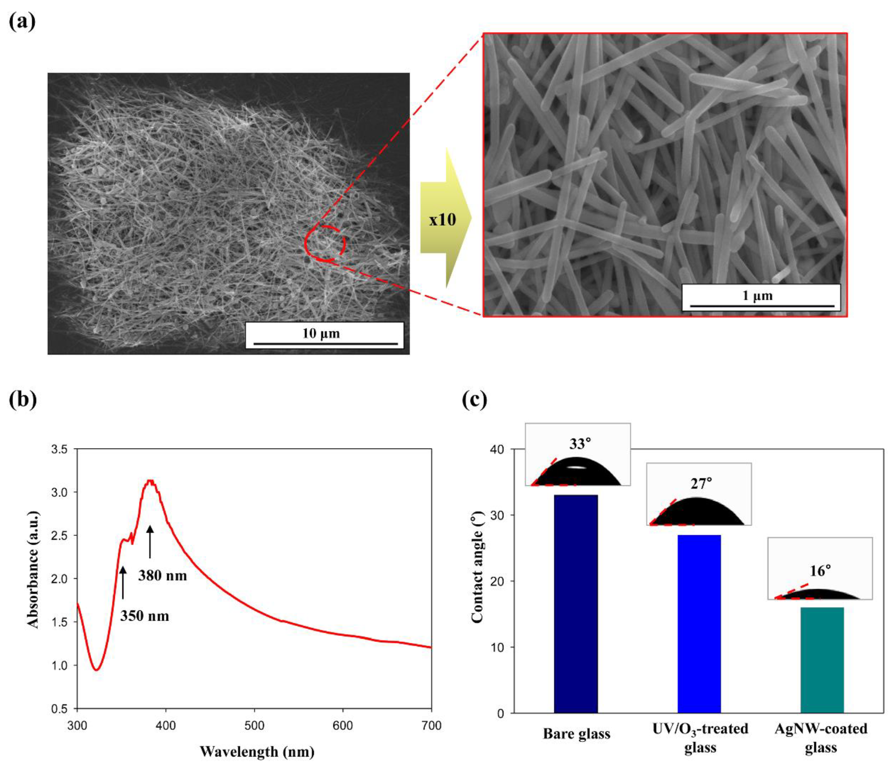
To confirm the successful preparation of the AgNWs, FE-SEM analysis was performed on the AgNW solution. As shown in
Figure 2a, AgNWs with a diameter of about 60 nm and a length of approximately 100 μm were synthesized to form a network. In addition, UV-vis spectrum of the synthesized AgNWs showed characteristic double peaks at around 350 and 380 nm corresponding to the plasmon resonance of bulk silver and transverse plasmon mode of AgNWs, respectively (
Figure 2b) [
28]. The prepared AgNWs solution was spin-coated on the glass substrate to form an AgNW network and produce a transparent electrode to replace conventional ITO [
29,
30]. The surface contact angle was measured by dropping DI water onto the AgNW-coated substrate to ultimately examine the surface energy changes caused by UV/O
3 pretreatment of the substrate and subsequent AgNW coating on the pretreated substrate. As indicated in
Figure 2c, the contact angles of the bare glass, the UV/O
3-treated glass, and the AgNW-coated glass were 33, 27, and 16°, respectively. Upon treatment of the surface with UV/O
3, hydroxyl groups were created, thereby imparting hydrophilic properties on the glass surface. Moreover, this decrease in the contact angle renders the introduction of an AgNW coating more facile due to hydrophilic interactions between hydroxyl groups of glass and hydrophilic pendent groups of PVP capping layer for AgNWs. As a consequence, this causes a further reduction in the contact angle. The fabricated AgNW surface of transparent electrodes was found to be hydrophilic due to the hydrophilic pendent groups of PVP capping layer, which induces vertical alignment of the LCs through polar interactions with the carboxyl groups of the nonionic amphiphiles. These results therefore confirm that the glass substrate was successfully coated with AgNWs to form an alternative transparent electrode to ITO.
To examine the electrical and optical properties of the prepared AgNW-coated electrodes, the resistance and optical transmittance were measured according to the concentration of AgNW solution. It should be noted here that the lower the resistance, the higher the electrical conductivity of the electrode; the resistance of the electrode must be as low as that of the commonly used ITO to be applicable [
31]. Thus,
Figure 3a shows the electrical resistance of the ITO substrate and the resistance values of the substrate coated with AgNW solutions of 3, 5, and 7 mg/mL, indicating values of 0.02, 0.7, 0.3, and 0.05 kΩ/cm
2, respectively. Upon increasing the concentration of the AgNW solution, the electrical resistance decreases due to differences in the densities of the resulting AgNW networks (see
Figure 3b). More specifically, at higher concentrations, the AgNW network becomes denser, thereby reducing the substrate resistance and allowing it to perform the role of an electrode. Importantly, the substrate coated with a 7 mg/mL solution of AgNWs exhibits comparable electrical resistance to ITO, while at lower concentrations, incomplete network formation resulted in higher resistance values and low electrical conductivity. It should also be noted that the use of a concentration greater than 7 mg/mL results in the formation of a thick electrode layer, which in turn produces a rapid decline in optical transmittance (i.e., <90%); accordingly, such a concentration is not suitable for electrode use for display applications. As can be seen in
Figure 3c, optical transmittances of 94.5, 92.1, and 90.4% at 550 nm were achieved for the three AgNW concentrations mentioned above, while ITO had a transmittance of 98.7% compared to bare glass. A concentration of 7 mg/mL was therefore considered optimal in terms of both the electrical resistance and the optical transmittance due to the complete AgNW network formation.
The POM images and black luminance levels of the LC cells were then obtained to confirm the degree of vertical alignment of the LCs based on the effect of the spontaneous alignment layer formation between AgNW network and nonionic amphiphiles (
Figure 4). Black luminance levels of LC cells were obtained by measuring the intensity of laser beam transmitted through LC cell under cross polarization. The test LC cells containing 0.5 and 1.0 wt% of nonionic amphiphile were fabricated by injecting the mixture of LCs with the nonionic amphiphile into the AgNW-coated cells using capillary force [
32,
33].
Figure 4a,c show POM images and black luminance levels of LC cells injected with LCs containing 0.5 wt% amphiphile. As the concentration of AgNWs increases, the degree of vertical alignment of the LCs increases slightly judging from the degree of darkness and black luminance level under cross polarization; however, the uniform vertical alignment in entire area is not possible due to the low concentration of amphiphile employed. As shown in
Figure 4b,d, upon increasing the AgNW concentration, the degree of vertical alignment is enhanced due to the higher amphiphile concentration employed, which gives greater quantities of noncovalently bonded amphiphiles on the AgNW surface, thereby increasing interactions with the liquid crystals. In addition to the amount of nonionic amphiphile employed, the AgNW concentration greatly influences the vertical alignment of the LCs. As shown in
Figure 4e, upon increasing the AgNW concentration, the amount of amphiphile that can form noncovalent bonds increases, and thus a large number of alkyl chains of the amphiphiles can induce stable vertical alignment due to strong interaction with the LC molecules. At AgNW concentrations lower than 7 mg/mL, AgNW network formation is insufficient to achieve perfect homeotropic alignment of LCs. This can be clearly observed in
Figure 4b,d, where at concentration of 3 and 5 mg/mL, a completely dark state cannot be realized.
As shown in
Figure 5, the voltage–transmittance (V–T) curves were measured to confirm the electro-optical characteristics of the manufactured LC cells. For comparison, a PI/ITO substrate was also fabricated and subjected to the same measurements. It is noted that high electrical resistance of the electrode induces the LC molecules to drive at a high voltage, leading to the increase in threshold voltage, which is defined as the voltage at the transmittance of 10%, of the LC cell. The PI/ITO substrate produced a threshold voltage of 2.21 V, while substrates of the 3 and 5 mg/mL AgNW-coated cells gave slightly higher values of 2.39 and 2.34 V, respectively. These results indicate that incomplete network formation of the AgNWs at low concentration resulted in high electrical resistance of electrode substrate, and thus it is not possible to induce a homogeneous alignment switching of the LCs at low threshold voltage. In contrast, the 7 mg/mL AgNW-coated cell exhibited comparable electrical resistance to ITO cell, and stable vertical alignment of LCs was achieved due to the sufficient noncovalent bonding between the amphiphile materials and the AgNW networks, which leads to excellent V–T characteristics with a low threshold voltage of 2.30 V. The V–T data therefore show that a successful electro-optical switching of homeotropic LC device can be induced using the AgNW-coated substrate and a mixture of LCs and the nonionic amphiphile. Thus, the AgNW-coated substrate is able to replace the ITO substrate, while the self-assembled molecular layer of nonionic amphiphiles can be sufficiently implemented as a vertical alignment material for LCDs to replace conventional PI.
As shown in
Figure 6, to compare the electro-optical performances of the AgNW-coated cells with those of PI/ITO cell, the rising time and decay time of each cell were measured to determine the response speed, which refers to the time it takes to repeatedly turn on and off a pixel. The measurement of response speed was based on gray-to-gray method, which is currently the most commonly used measure of response time. This method measures, in terms of time, the display transitions from dark gray to light gray (rising time) or from light gray to dark gray (decay time), whereby 10% transmittance was set to dark gray and 90% to light gray [
34,
35,
36]. It can be seen in
Figure 6 that the rising time of the conventional PI/ITO substrate is 22 ms and the decay time is 15 ms. Similarly, the rising times of the AgNW-coated cells were 77, 62, and 30 ms for AgNW concentrations of 3, 5, and 7 mg/mL, respectively, while the decay times were 36, 28, and 20 ms, respectively. The low response speeds of the 3 and 5 mg/mL AgNW-based cells were due to insufficient formation of the AgNW network, resulting in low electrical conductivity and imperfect vertical alignment of LCs. As a result, the LC molecules cannot be rapidly switched under applied voltage. This slow response time has a disadvantage in that it takes a long time for the color or contrast of pixels to change, causing flickering of the screen or reducing the resolution. In contrast, the cell coated with 7 mg/mL AgNW exhibited a faster response speed than the other cells, resulting in a high performance similar to that of a PI/ITO substrate. Due to the formation of a denser and more complete AgNW network, the spontaneous alignment layer formation of nonionic amphiphiles on the AgNW surface was excellent, and voltage control of LCs was facile owing to low resistance of AgNW electrode, thereby resulting in an excellent response speed. This in turn can prevent flickering of the screen and maintain an excellent resolution.


