1. Introduction
Liquid crystalline materials have been of particular interest for several decades because of their anisotropic structural properties that can induce unique electric, magnetic or thermal responding behaviors [
1,
2]. A variety of anisotropic physical properties exhibited by liquid crystals (LCs) strongly depend on the specific molecular arrangement, which depend on the orientation of LC molecules [
3]. It was demonstrated that physical properties of LCs may be changed by doping with different types of nanoparticles [
4,
5,
6,
7]. The doping process of LCs can prepare novel materials that can have additional very interesting properties which are absent in original LC substances which can offer many practical applications in nanosensors development, liquid crystal display industry, optical processing, photonics and magneto-optics [
8]. Nematic liquid crystals (NLCs) doped with magnetic nanoparticles (ferronematics) are magnetically active anisotropic fluids which are a manifestation of the original idea [
9] that suggested that doping liquid crystals with fine magnetic particles may enhance their sensitivity to magnetic fields. Experiments on ferronematics confirmed that magnetic particles affect, considerably, the behavior in external fields and proved also that the interaction between the host liquid crystal molecules and magnetic particles is interesting and quite complex [
10,
11,
12,
13,
14,
15,
16]. Molecules of LCs can be generally oriented under electric or magnetic fields due to the anisotropy of dielectric permittivity or diamagnetic susceptibility [
17]. Comparing electric fields in which the driving voltages are in the order of a few volts, the magnetic field necessary to align NLCs, because of the small value of the anisotropy of the diamagnetic susceptibility, must reach rather large values.
The essential feature of ferronematics is a strong coupling between magnetic particles (characterized by average magnetic moment
m) and NLC matrix (characterized by the preferential direction of the nematic molecules—director
n). The coupling between
m and
n under the applied magnetic field can in this way result in the reorientation of NLC molecules [
18,
19]. So that the applied magnetic field changes the orientation of magnetic particles and due to the coupling between magnetic particles and LC molecules the director
n follows it. However, anisotropic properties of ferronematic samples strongly depend on their internal structure, which is determined by a shape of the particles as well as by the initial orientations of the director
n and vector
m. The usually used small volume concentration of magnetic particles ensures that the inter-particle magnetic dipole-dipole interaction can be ignored.
As we have shown, the surface acoustic wave (SAW) technique can be very useful tool for the investigation of structural changes in NLCs doped with various kinds of nanoparticles [
20,
21,
22]. The advantage of this SAW technique is that, compared to the case when the longitudinal wave is used, only a very thin layer of NLC is required. Such SAWs, generated on a piezoelectric substrate propagates along the surface as an elliptically polarized wave, with the amplitude decaying into substrate. After reaching a liquid, such as a NLC, placed on its path, the SAW amplitude is exponentially attenuated and propagates in the following way as a leaky surface wave at the NLC/substrate interface. The reason is the generation of a longitudinal wave into NLC, the conversion of which is caused by the vertical displacement of SAW in the surface. So that, two modes are then introducing as a combination of longitudinal and shear vertical particle displacement. This is in the contrast to the shear mode of SAW that is representing only by a shear horizontal wave on the surface of solid substrate [
23,
24]. A SAW due to the strongly absorbed longitudinal wave by the NLC that is subsequently indicated by the decreasing amplitude of SAW in the direction of SAW propagation can be applicably utilized for the study of NLC structural changes. The response of SAW attenuation can then reflect sufficiently on any changes in NLC orientational properties initiated by applied fields and/or by changed other external conditions. In this contribution, we report results of investigation of NLCs doped with magnetic particles of nanorod shape and different concentrations to determine their effect on structural changes under external weak magnetic and/or electrical fields as well as the temperature influence on structural changes using SAW. The obtained SAW results are supported by some optical investigation, too. In addition, the theoretical background of the utilized SAW investigation is presented.
2. SAW in Liquid Crystals
Acoustic (ultrasonic) methods have been used over several decades to study rheological properties of liquid crystals. Most of the described acoustic experiments utilize two main types of acoustic waves, namely longitudinal acoustic and shear waves. These methods differ in the direction of oscillating motion of particles in respect of the direction of wave propagation. In the case of longitudinal waves both directions coincide, while in the case of shear waves they are normal to each other. As shear waves differ from longitudinal ones by transverse direction of oscillations of particles with respect to the wave vector, their propagation in liquid crystals is quite different from the longitudinal wave propagation. These types of waves are also quite different from the point of view of experimental arrangement and obtained results. As we have shown, in our experimental arrangement we are actually using configuration in which the generated oscillating motion of particles relative to the direction of wave propagation is normal to each other, like in the case of shear waves, but with vertical orientation of oscillations.
An acoustic wave generated on a solid substrate such as a Rayleigh wave (SAW) propagates along the substrate surface as an elliptically polarized wave, with the displacement amplitude decaying into the substrate. Generally, when a liquid (such as NLC) is placed on its path, the amplitude of SAW after reaching a liquid is exponentially attenuated, propagating along as a “leaky surface wave” at the NLC/substrate interface due to the generation of a longitudinal (compression) wave in the fluid. This mode creation is caused by the vertical displacement of generated SAW on the surface. The longitudinal wave itself propagates at the Rayleigh angle,
[
25], where
and
are propagation velocities of the longitudinal wave in the fluid and the Rayleigh wave on the substrate, respectively. So that when the substrate is in contact with the liquid, SAW irradiates a longitudinal wave into liquid giving rise to the propagation losses. The cumulative attenuation through that path along the fluid/substrate interface is then the sum of
and
, where
is the attenuation of a fluid-damped Rayleigh SAW and
is the attenuation of a plane longitudinal wave in a viscous but isotropic fluid. This is the case which could be recently successfully applied for the investigation of structural changes in oil-based magnetic fluids [
26]. Symbols
and
are the dynamic (shear) and volume (bulk) viscosities, respectively,
and
are the fluid and substrate densities, respectively,
ω is the angular frequency and
λSAW is the SAW wavelength. One of the main differences between the bulk and shear viscosities is the frequency dependence of these parameters. Whereas the shear viscosity is frequency dependent at extremely high frequencies (˃1 GHz), the bulk viscosity can show the frequency dependence at the region of frequencies usually realized at ultrasonic measurements (1–100 MHz) [
27,
28]. However, in the case of NLC the formulation of α
f is more complicated. The flow behavior of NLC differ fundamentally from that of isotropic liquids because of mutual coupling between flow direction, director orientation and viscosity.
The previously described Rayleigh modes represented by a combination of longitudinal and shear vertical particle displacement are in contrast to the shear mode of SAW, usually utilized for LCs viscosity measurements or in SAW sensor [
23,
24,
25,
26,
27,
28,
29,
30]. While for the acoustic liquid sensor, an acoustic wave device requires to have the low energy loss into a liquid and the longitudinal component should have negligeable attenuation, in the case of Rayleigh wave propagated in a viscous liquid because of the normal component of the acoustic wave, generates in contact of the solid-liquid interface a longitudinal wave that leads to extreme attenuation of SAWs. Providing that the transit of Rayleigh wave is sufficiently large, this component is efficient to attenuate excessively and by that change Rayleigh wave characters. However, the result of the interaction between SAW and liquid can be also an internal streaming [
25,
26,
27,
28,
29,
30,
31]. If the low power SAW and very short pulses (~1 µs) are used, the effect of streaming can be ignored. So that, the SAW attenuation response just due to the longitudinal wave that is strongly absorbed by liquid crystals and subsequently detected through the SAW amplitude can be successfully utilized for the investigation of internal structural changes influenced by external conditions as external fields or temperature.
A complete theoretical description of anisotropic propagation of acoustic wave in NLC was considered by number of authors in the framework of hydrodynamic approximation [
32,
33,
34,
35]. The main practical use, it seems, has the Leslie–Ericksen hydrodynamic theory. Nevertheless, the most essential results were obtained after modification of older instruments and elaboration of new ones to provide viscosity measurements at different orientations of liquid crystals fixed by strong external fields which was first introduced by three basic geometries for viscosimetric measurements [
36,
37].
The earlier theoretical work using hydrodynamic theory of compressible NLC led to the following expression for ultrasound attenuation [
32,
33,
34,
35,
38]:
where
c is the ultrasound velocity,
f is the frequency,
ρ is the density,
θ is the angle between
n direction and wave vector and
(
i = 1–5) are viscosity coefficients. The coefficient
is shear viscosity coefficient when the molecular axes are normal to the direction of shear flow and to the velocity gradient, the coefficients
and
are related to the other two shear viscosity coefficients. The coefficients
−
and
represent bulk viscosities.
The relation for an absorption coefficient
α of a longitudinal acoustic wave propagating in NLC can be also expressed using Leslie coefficients
(
i = 1–5) as [
39]:
or after some modifying as:
where
are bulk viscosity coefficients,
are Leslie coefficients for incompressible LC. The obtained expressions are close to those presented earlier [
34] except the combination (
), entering Equations (4) and (5). This combination results from an account of director oscillations in an ultrasonic wave, which were ignored in the work mentioned above. Moreover, the Equation (4) is analogous to well-known results [
32] and frequently used for the analysis of acoustic properties of liquid crystals [
39]. Both the general expression (4) and modified (5) are valid in the latter case at the next substitutions
using previous notation. While coefficient
is characteristic for isotropic liquids,
and
have the connection with rotational viscosity by the coefficient
that generally determines the rate of relaxation of the director or torque viscosity by the coefficient
. The coefficient
λ is defined by ratio
. The coefficient
is related to the tension deformation [
35]. These results show that acoustic studies of liquid crystals can provide a lot of useful information on rheological properties of liquid crystals [
39].
Later, three basic geometries for viscosimetric measurements using shear waves were introduced and they are used until now [
36,
37,
38]. The anisotropic viscosity is described by three fundamental viscosity coefficients
(
i = 1–3) referring to three different orientations of director
n with respect to the direction of the flow velocity
v and the
denotes the viscosity for the case
,
for
, and
for
n being perpendicular to both
n and
. It is necessary to note that alternative notations of the principal viscosity coefficients
can be found in the literature, in particular, the definitions of
and
are frequently interchanged and coincide with those proposed originally [
39]. In a general case of arbitrary orientation of acoustic wave using shear viscosity coefficients can be written as:
where
θ is angle between flow direction and director
n and
φ is angle between projection of
n to
xy plane (determined by
and
) and
. The principal shear viscosity
and the parameter
can be easily connected with Leslie coefficients
via well-known expressions [
32,
33]:
For NLCs aligned by intensive flow, an additional expression of viscosity for the shear viscosity coefficient
can be derived from (7) as:
In principle, expressions (8) and (9) can be used to determine Leslie coefficients via anisotropic shear viscosity measurements similarly as relation (3) to determination of viscosity coefficients using longitudinal acoustic waves. All presented theoretical procedures could be utilized for the acknowledgement of applicability of our SAW experimental technique.
3. Experimental
Samples of ferronematic LC were based on the thermotropic nematic 4-(trans-4′-n-hexylcyclohexyl)-isothiocyanatobenzene (6CHBT), which has high chemical stability, low viscosity and change their phase with respect to the temperature from a well-ordered crystalline (
TCN = 12.1 °C) over to a less ordered nematic and finally to a disordered, isotropic phase (
TNI = 42.8 °C). The investigated nematic LC was doped with magnetic Fe
3O
4 nanorods. The magnetic Fe
3O
4 nanorods are prepared by the processing of magnetite and goethite with estimated particle length from 200 to 500 nm and added in various volume concentration in 6CHBT matrix [
40]. The samples were placed into measuring cell were pre-heated above the temperature of its isotropic state (~50 °C) and ultrasonically mixed for 2 h to ensure homogenous distribution of nanoparticles inside host LC.
The SAW pulses (~1 µs) of frequency 10 MHz were generated by the interdigital transducer prepared on the LiNbO
3 substrate, using hf pulses from the Pulse Modulator of MATEC 7700 and another transducer was used for the receiving of SAW signal by Receiver of MATEC 7700. The SAW attenuation was recorded by MATEC Attenuation Recorder 2470 A or using Gated Integrator and Boxcar Averager SR 250. The complete experimental arrangement configuration has been already described [
21,
22]. The cell with the LC sample of thickness D ≈ 100 μm, supplied by gold electrodes, was placed on the center of the LiNbO
3 substrate and installed in the sample holder that was component of the thermostatic measuring chamber. The determined maximal deviation for Δ
α measurement was ±0.02 dB. The LABVIEW system was used to drive the experiment including sources of magnetic field or voltage. The initial intrinsic arrangement of NLC in the case of SAW attenuation measurements was supposed to have a predominate alignment in the plane of electrodes. The director
n was in that case parallel to electrodes and applied magnetic or static electric fields, for the investigation of influence of applied fields on the SAW attenuation, were perpendicular to them. However, at the anisotropy measurements the sample chamber could rotate to change the angle
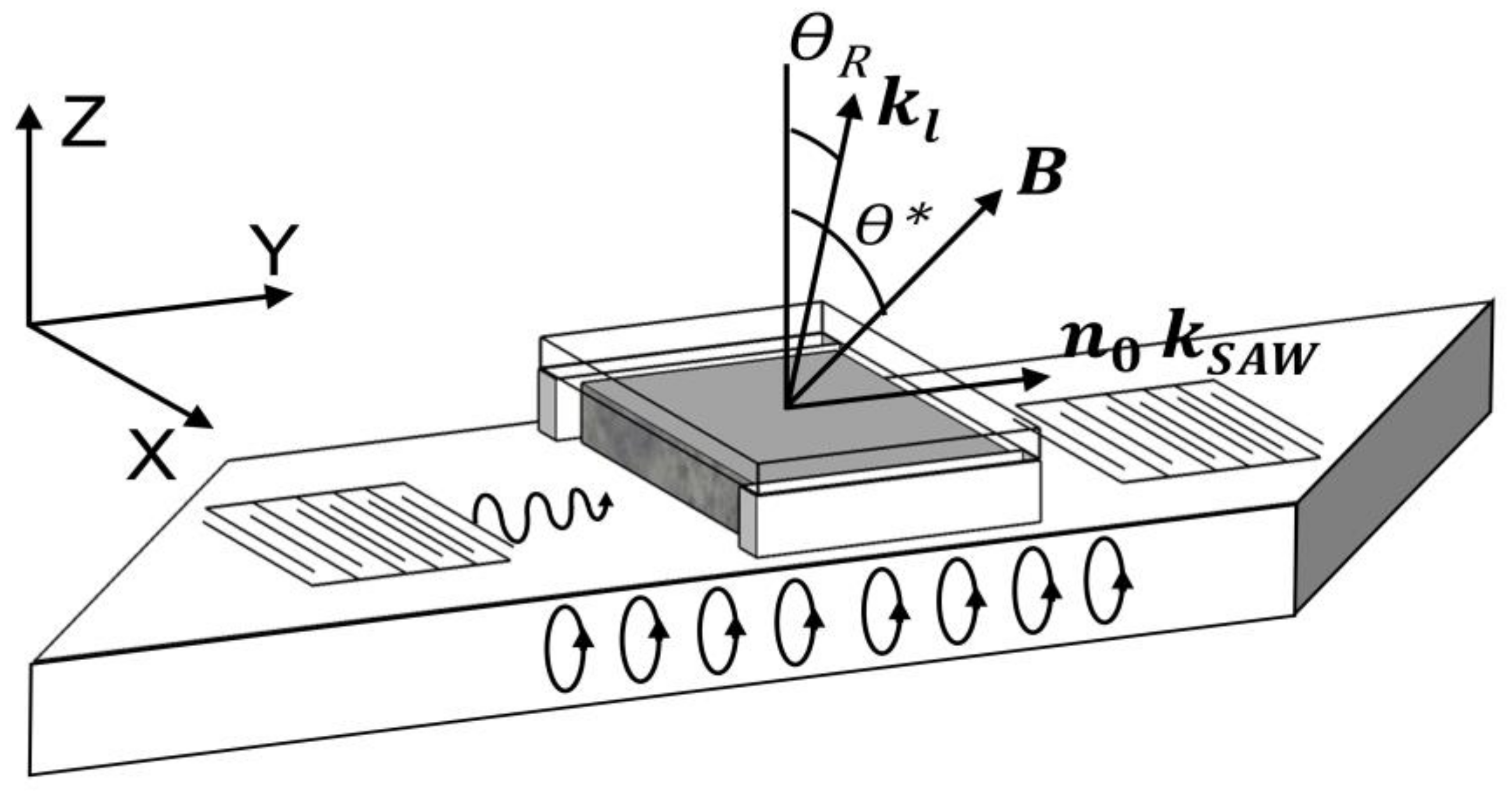
θ* between magnetic field direction and direction perpendicular to the cell plane (
z direction) (
Figure 1).
To find the effect of magnetic nanorods on optical properties, the dependence of optical transmission on the applied fields was investigating with the usage of linearly polarized semiconductor laser beam (532 nm, 8 mW) passing through the cell’s glass with 50 μm gap using optical triangular prisms and polarizers. The intensity of transmitted light was recorded as a function of the magnetic field by a semiconductor photodetector connected to the computer via multimeter. The experimental arrangement for investigation of optical transmission behavior, in more detail, has been already described [
21,
41].
4. Results and Discussion
Structural changes in investigated NLCs under both magnetic and electric fields were monitored taking use of the measurements of the attenuation of SAW propagating along the interface between the LiNbO
3 substrate and the NLC cell. In the case of SAW attenuation measurements, the initial intrinsic arrangement of NLC molecules including magnetic nanorods was supposed to have a predominate alignment in the plane of electrodes due to the interaction between magnetic moment of magnetic nanorods
m and director
n. Both external magnetic and electric fields were then applied perpendicular to them. Applied magnetic and/or electric fields turn the magnetic moments or dipole moments of magnetic nanorods to their direction and consequently due to the orientational coupling between NLC molecules and magnetic nanoparticles they influence, also, the changes the orientation of director
n. The applied fields turned by this way LC molecules and, finally, gradually changed their orientation in stages, starting at the center [
24], towards the direction perpendicular to the cell surface. The SAW generated on the LiNbO
3 substrate after reaching a NLC cell propagates as a leaky surface wave at the NLC/substrate interface due to the generation of a longitudinal wave into the liquid crystal. The interaction of this longitudinal wave with NLC layer can enable to detect the changes of SAW attenuation when NLC molecules change their orientation due to the applied field. The SAW then due to the strongly absorbed longitudinal wave by NLC, which is sequentially indicated by the amplitude of SAW, is utilized for the investigation of NLC structural changes. The magneto-optical behavior was investigated in the same set of NLCs doped with magnetic nanorods using the arrangement described in the previous paragraph. The light transmission was expressed in the case of parallel polarizers as
I/I0, where
I0 and
I are the intensity of incident light passing through the NLC cell without applied field and under the field, respectively.
The dependences of SAW attenuation on the linearly increasing magnetic field at a constant rate (15 mT/min) and temperature 20 °C measured for investigated samples of NLC doped with nanorods are shown in
Figure 2. This figure presents SAW attenuation changes for magnetic flux density
B perpendicular to the cell (
xy plane) and wave vector
kSAW (
y-direction) for samples with different concentrations of particles, including pure NLC. It shows both on the decrease of the threshold field for all concentrations according to pure NLC and on the important role of the particle concentration on structural changes. The observed dependencies can be resolved into three main phases, very weak increase up to ~160 mT, depending on the concentration, followed by a faster increase that gradually merges into saturation. The faster increase of the attenuation corresponds to the main process of LC molecules reorientation. The interesting feature, similarly as in some cases of our previous investigations [
21,
26], is also that the higher concentrations of particles (10
−4 and 5.2 × 10
−4) does not ensure automatically the highest influence of magnetic field on structural changes. The reason of the less marked rise of the attenuation comparing with lower concentrations can be in the creation of some clusters or aggregates due to too high concentration of magnetic particles which results in a decrease of structural changes [
42,
43]. As for the memory effect observed in the decreasing regime, in the case of samples with lower concentrations (10
−5 and 5 × 10
−5), except the hysteretic development, no remainder attenuation was registered at zero magnetic field, however, in the case of higher concentration (10
−4 and 5.2 × 10
−4) it represents about 10% and 20%, respectively. Similar effect of concentration on function of Δ
α (
B) dependences was already observed in the case of 6CHBT doped with other dopants [
20,
21,
44,
45]. Comparing presented structural changes with those obtained on 6CHBT doped with rod-like [
44], chain-like [
45] or spherical [
20] magnetic nanoparticles, these changes belong to less marked, they are close to that doped with chain-like nanoparticles, where the length was comparable with investigated nanorods.
The effect of electric field on the SAW attenuation in investigated NLC samples for all concentrations, including pure 6CHBT, reflecting structural changes, is shown in
Figure 3. The external voltage linearly raised from zero to 10 V during 10 min. The development of SAW attenuation response that reflects the role of nanoparticles concentration on both the threshold voltage and total structural changes, shows similarly as in the case of magnetic field three main regions: After the almost constant attenuation at lower voltages follows a faster increase and again the slower increase converging to the saturation. Obtained results demonstrate, that electric field due to the dipole moments of magnetic nanorods strengthens the reorientation of the director
n towards its direction and the threshold voltage is shifted to the lower values with increasing volume concentration. However, the sample with the largest concentration of nanorods (5.2 × 10
−4) seems to have two thresholds, one that coincides with previous presentation and another that is shifted to higher voltages. The significantly higher change of acoustic attenuation comparing with pure NLC and by that the larger effect of doping with magnetic nanorods on structural changes was evidently detected for all concentrations, but the largest increase was observed in the case of lowest concentration (10
−5) followed then by the decrease with increasing concentration. So that it is evident the effect of nanorod electric dipole moments on NLC molecules.
Figure 4 shows the light transmission as a function of magnetic field for 6CHBT liquid crystal doped with three different concentrations of magnetic nanorods (5 × 10
−5, 10
−4, 5.2 × 10
−4) including pure one. The interesting feature is that the decrease of the light transmission to the minimum value after reaching the threshold field is accompanied with superimposed oscillations. It is assumed that during the lowered threshold field a planar aligned molecular director undergoes a reorientation between initial planar and final perpendicular and this process of reorientation is clearly revealed by the ellipticity variation. So that, when the LC is subjected to a laser beam, a succession of maxima and minima of the transmitted light through the NLC cell appears [
46,
47]. The same situation becomes when
B is turned off and the NLC returns to the initial planar orientation. These oscillations are present, but much greater, also on the curve corresponding to the pure NLC and indicate the fact that they are the peculiarity of LC molecules under magnetic field. The characteristic for the lowest concentration (10
−5) is not included in
Figure 4 because of currently registered large oscillations with very similar development to that of pure NLC. The next significant feature of presented magneto-optical characteristics is the shift of threshold field towards to lower fields with increasing nanorods concentration. Another attribute of magneto-optical characteristics, comparing with SAW measurements, is the increase of threshold field
Bc due to its dependence on the NLC cell thickness
D (
Bc ~ 1/
D) [
12]. Presented magneto-optical results coincide well with our previous obtained on the same NLC doped with different nanoparticles [
41].
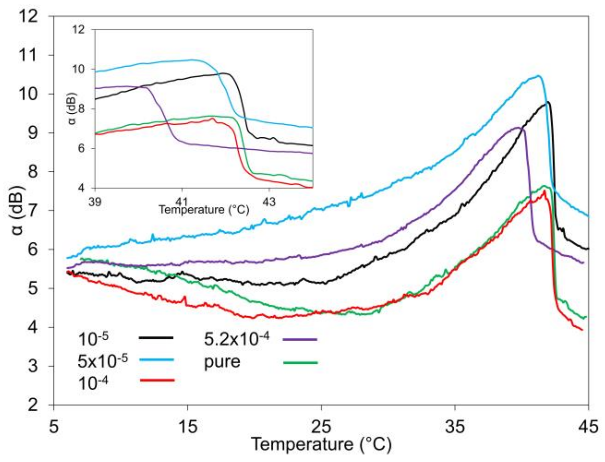
The temperature dependences of acoustic attenuation measured at frequency 10 MHz for samples of investigated NLCs are illustrated in
Figure 5. The SAW attenuation in the case of both pure NLC and doped NLC samples shows very similar development, unrecorded change at temperature corresponding to the crystal-nematic transition (
TCN) followed by the small decrease or almost stable attenuation with increasing temperature until ~25–30 °C, depending on the nanorods concentration, followed by the rapid increase up to the temperature of ~42 °C when the structural changes to isotropic phase (
TNI) are represented by a strong decrease of the SAW attenuation (see also detail). Presented temperature dependences show also on the role of the concentration on the shift of nematic-isotropic transition to lower temperatures, decreasing in small successive steps with increasing concentration. The most expressive decrease was registered only in the case of highest nanoparticles concentration. The shift of phase transition towards lower temperatures for doped NLC can be related to the increase of volume of impurities, occurring in the NLC during nanorod synthesis, due to the increasing nanoparticles concentration [
48]. Another reason for nematic-isotropic transition decrease can be attributed to the anchoring interactions between NLC molecules and nanoparticle surfaces that can cause the disorganize of the NLC order [
49]. The role of frequency on temperature dependences of SAW attenuation for pure 6CHBT is illustrated in
Figure 6 for two SAW frequencies, 10 and 20 MHz. As it can be seen, different frequencies are differently sensitive to processes that are in progress in NLC during varying temperature. The temperature dependence measured at 40 MHz (not included into
Figure 6) was not able to distinguish any transition point. The measurement performed using longitudinal acoustic waves at 5.2 MHz on the same NLC (6CHBT) [
50] also fully support our results. The temperature behavior of NLC, especially in the vicinity of transition point can be explained by the fluctuation of order parameter and/or increase in the bulk viscosity coefficients [
41,
50]. If we take into account the supposition [
27,
28] that the shear viscosity is frequency dependent at high frequencies and the bulk viscosity can show the frequency dependence at the region of frequencies realized also at our acoustic measurements, these results support the assumption about the bulk viscosity coefficients responsible for our SAW measurements, alike as in the case of longitudinal acoustic wave.
The dynamics of the switching processes for different values of magnetic field (200, 300 and 400 mT) measured using SAW attenuation and optical transmission are shown in
Figure 7. The effect of applied field in pulsed regime running 120 s corresponds to obtained both SAW dependences (
Figure 2) and magneto-optical characteristics (
Figure 4). Structural changes initiated by applied field reached the saturated state during the time depending on the values of magnetic field. The behavior of magneto-optical time responses corresponds to SAW attenuation responses for the same magnetic field and concentration. However, after the magnetic field of 400 mT was applied the switching time was shortest but with some superimposed oscillations when the light transmission decreases to its minimum. Then it achieves its equilibrium state. Oscillations, when the magnetic field is switched on or switched off, were observed in the same NLCs doped with spherical and/or chain-like magnetic nanoparticles [
41] but also when the electric field was applied in electro-optical experiments [
51,
52]. The origin of these oscillations can be attributed to the directional redistribution of NLC molecules around the equilibrium position of the nematic director, from uniform (planar) alignment on the cell surfaces to the perpendicular at the center of the NLC layer, during magnetic field increasing [
52]. The magneto-optical characteristics without any oscillations after reaching their minimum were observed in the case of rod-like nanoparticles [
44] and some carbon nanotubes (CNT) [
21] when the SAW signal and, by that, structural changes were stable that is important for switching processes application. It is evident that the shape and particularly length of nanoparticles along with concentration play crucial role for stability of magneto-optical behavior and the stronger anchoring in the case of rod-like particles (rigid anchoring) [
41] ensures the stabile magneto-optical responses.
The dependences of acoustic attenuation
Δα on angle
θ* (anisotropy) measured at magnetic field 300 mT for two concentrations (5 × 10
−5, 5.2 × 10
−4) are shown in
Figure 8. The
θ* is angle between
z direction which is perpendicular to the cell plane and magnetic field orientation (see
Figure 1). It should be noted that the acoustic attenuation is the sum of surface and volume acoustic attenuation (Equations (2) and (3)). The surface acoustic attenuation is almost independent of temperature and its calculated value is ~175 m
−1. As it can be seen the SAW attenuation increased with increasing angle. The measurement started after 5 min of stabilization at perpendicular orientated magnetic field
B (0 degree) in the direction of SAW wave vector
kSAW. Then the angle was changed by 10 degrees after 2 min of stabilization to 90 degrees (parallel orientation). The relation between measured angle
θ* and angle
θ from Equations (3)–(8) is given by the expression:
where the calculated Rayleigh angle,
≈ 22 degrees. The measured dependence of SAW attenuation α on angle
θ* (anisotropy) can be fitted by:
from which the dependence of Δ
α on angle
θ* illustrated in
Figure 7 is:
that is after application of Equation (9) in perfect accordance with some previous results of NLC investigation using longitudinal acoustic waves [
53,
54,
55]. The character of presented anisotropy measurements realized on nematic liquid crystal 6CBHT doped with nanorods can be supported also by anisotropy measurements observed on the same NLC (6CHBT) but doped with functionalized multi-walled carbon nanotubes (MWCNT/Fe
3O
4) [
21] (see
Figure 9). Angle
θ* determined from both anisotropy measurements is ~12–15 degrees that is compared to calculated value (~22 degrees) for pure 6CHBT something lower value. However, the velocity of longitudinal wave decreases with increasing concentration of nanoparticles [
56,
57], that can be reason of the difference. The comparison of these results with Equation (3) but also Equations (4) and (5), after substitution given by Equation (6), indicates that the bulk viscosity coefficients should dominate the SAW attenuation. While relations (7)–(9) could be used in the case of shear acoustic wave [
24,
25,
26,
27,
28,
29,
30,
31,
32,
33,
34,
35,
36,
37,
38,
39], their application in our SAW investigation due to the different direction of oscillations does not appear as appropriated, primarily due to the generation of longitudinal wave in our experimental configuration that is responsible for SAW attenuation response. Nevertheless, as our SAW investigations are orientated first of all to monitoring of the role of magnetic dopants on structural changes under external fields, the presented SAW techniques completely satisfy the acquirements of relevant information concerning the influence of magnetic nanoparticles on NLCs behavior.

 ,
, 


