Next Article in Journal
Restoration Mechanisms at Moderate Temperatures for As-Cast ZK40 Magnesium Alloys Modified with Individual Ca and Gd Additions
Previous Article in Journal
Microstructural and Hardness Evolution in a Duplex Stainless Steel Processed by High-Pressure Torsion
Previous Article in Special Issue
Enhanced Thermoelectric Properties of WS2/Single-Walled Carbon Nanohorn Nanocomposites
 
 
Correction published on 22 April 2022, see Crystals 2022, 12(5), 583.
Article

Synergistic Effect of MWCNT and Carbon Fiber Hybrid Fillers on Electrical and Mechanical Properties of Alkali-Activated Slag Composites

1
School of Civil Engineering, Chungbuk National University, 1 Chungdae-ro, Seowon-gu, Cheongju 28644, Korea
2
Institute of Advanced Composite Materials, Korea Institute of Science and Technology (KIST), 5 Hwarang-ro 14-gil, Wolgok 2(i)-dong, Seongbuk-gu, Seoul 02792, Korea
*
Authors to whom correspondence should be addressed.
Submission received: 6 November 2020 / Revised: 10 December 2020 / Accepted: 12 December 2020 / Published: 15 December 2020 / Corrected: 22 April 2022
(This article belongs to the Special Issue Carbon Nano-Composite Materials)

Abstract

:
Herein, we investigated the synergistic effect of multi-walled carbon nanotube (MWCNT) and carbon fiber (CF) hybrid fillers on electrical and mechanical characteristics of alkali-activated slag (AAS) composites. Many studies on AAS composites have been conducted in the past; however, not much progress has been made regarding characteristics of AAS composites with hybrid conductive fillers. The specimens with different mix proportions were fabricated in the present study, and numerous material characteristics, including flowability, electrical resistivity, and compressive strength of AAS composites were measured. In addition, the synergistic effects were investigated through scanning electron microscopy and thermogravimetric analysis. It was found that the 0.5 wt.% of MWCNTs and CFs lead the effects of the bridging and reducing crack propagation, thereby improving its electrical and mechanical performances. The filler exceeding a percolation point improved the electrical performance of the AAS composites; however, it interfered with the hydration process during the curing period, and caused a decrease in compressive strength of AAS composites.

1. Introduction

Climate change due to industrial development and an increase in greenhouse gas emissions is considered a critical problem, and global efforts are focused on researching and preparing countermeasures [1]. The increase of greenhouse gases in the atmosphere can bring numerous climate changes, such as rising temperatures, changing ecosystems, and increasing natural disasters. Thus, the United Nations Framework Convention on Climate Change (UNFCCC) has tried to reduce greenhouse gases to prevent abnormal climate phenomena.
Portland cement has been used most widely on construction fields. However, it produces a large amount of carbon dioxide (CO2) emissions, which is about 8% of global greenhouse gas emissions [2]. As the need for CO2 reduction has emerged, as above, research on replacing Portland cement is actively being conducted worldwide with industrial by-products, such as alkali-activated cement [3,4,5]. The utilization of alkali-activated cement is expected to reduce CO2 emissions through recycling of industrial by-products, along with distinct advantages distinguished from Portland cement, such as reducing heat of hydration, rapid strength development, and remarkable chemical resistance.
On the other hand, recent studies that give functionality to existing construction materials are being actively conducted [6,7,8,9]. Construction materials where carbon-based fillers (e.g., multi-walled carbon nanotubes (MWCNTs), carbon black, graphene, and carbon fibers (CFs)) are properly dispersed can improve electrical and mechanical properties, which are expected to be applied to future smart structures. The representative examples of application studies of functional composite materials include self-heating, thermal insulation, electromagnetic wave shielding, and monitoring [10,11,12,13]. Furthermore, energy harvesting studies, such as piezoelectric and thermoelectric, are also actively conducted in recent years in line with future demand [14,15].
In this study, MWCNTs and CFs incorporated alkali-activated slag (AAS) composites were fabricated and investigated for verifying electrical and mechanical properties. Many studies on AAS composites have been conducted in the past [16,17,18,19,20]. However, not much progress has been made regarding characteristics of AAS composites with hybrid conductive fillers. Herein, the AAS composites used in the experiment produced the various contents of the MWCNTs and CFs. The fluidity value, electric resistivity, and compressive strength were measured with the related adequate standards. In addition, the internal structures and chemical properties were investigated through scanning electron microscopy (SEM) and thermogravimetric analysis (TGA).

2. Materials and Methods

2.1. Raw Materials

The chemical compositions of ground granulated blast-furnace slag (GGBS; Hyundai Steel Co., Ltd., Seoul, Korea) and Class-F type fly ash (Hadong thermal power plant operated by Korea Southern Power Co., Ltd., Republic of Korea) used in this study as binder material were measured by X fluorescent spectrometry (XRF) and summarized in Table 1. In addition, Table 2 lists the mix proportion of alkaline solution used in the present study. An alkali activator was obtained by blending sodium hydroxide pellets (Duksan Chemicals Co., Ansan, Korea), sodium silicate solution (Duksan Chemicals Co., Ansan, Korea; Na2O: 9.2%, SiO2: 33.3%, H2O: 57.5%), and water. Silicate modulus of 1.1 (Ms = ratio of SiO2/Na2O) was selected because the Ms of 1.1 is general value in terms of physical properties, such as mechanical, flowability, and setting time [7,8,9,21,22,23]. MWCNTs (Jeno Tube 8 ©, JEIO Co., Ltd., Ansan, Korea) with a purity level of 98.5% and PAN-based CFs (ACE &Tech, Ltd., Youngju, Korea) were used to prepare an electrically conductive specimen [24,25]. The length and diameter of MWCNTs were 100–200 μm and 7–9 nm, respectively, and those of PAN-based CFs were 5 mm and 6 μm, respectively.

2.2. Experimental Details

Table 3 lists the mix proportion of AAS composites. To investigate the synergistic effect between nano and micro fillers, MWCNTs and CFs were simultaneously used in this study. The contents of MWCNTs and CFs used for preparing the AAS composites varied from 0.0% to 2.0% and 0.0% to 1.0% in weight of cement. In all specimen, the activator/binder ratio was selected in accordance with the flow value, which corresponded to 105 ± 5 mm.
The various mixes of AAS composites were prepared from GGBS and fly ash binders by varying contents. The method of producing AAS composite is as follows: Initially, dry mixture was prepared by mixing GGBS, fly ash, MWCNTs, and CFs. The MWCNTs were dry-mixed into the binder by 0, 0.1, 0.5, 1.0, and 2.0% in terms of the weight of the binder material (slag + fly ash) before mixing with water. The CFs were also mixed with the binder by 0, 0.5, and 1.0 wt.% in the dry state. Secondly, sodium silicate and sodium hydroxide pellet were mixed to induce a chemical reaction of the binder material. Thus, an alkali activator corresponding to silicate modulus 1.1 was prepared. Third, the alkali activator was added into a dry mixture and mechanically mixed for 5 min by using mortar mixer (HJ-1150, Heungjin Testing Machine Co., Ltd., Gimpo, Korea) until a homogeneous mixture was obtained. The alkali activator was used for the target flow of AAS specimens (105 ± 5); therefore, the amount varies slightly for each specimen. Fourth, the mold was filled with mortar mixture and has a 25 × 25 × 25 mm3 cubic size. After casting, the specimens were sealed with plastic wrap to prevent the evaporation of moisture and were stored in a curing chamber at a controlled temperature of 20 °C for 24 h. Finally, they were dried at an atmosphere condition with plastic wrap to prevent the evaporation of moisture for 3 days. After 3 days, each specimen was then dried in an oven at 60 °C for an additional 25 days. The size and approximate composition of the fabricated specimen are illustrated in Figure 1.
The mix proportion in Table 3 was designed by setting the flow to the same value in consideration of the field applicability and low electrical resistivity of the specimen. However, the hardened structure and properties of alkali-activated materials are quite sensitive to the amount and composition of the activator, therefore, the proposed formulation is considered to have limitations in the analysis of the mechanisms.

2.3. Characterizations

To analyze the electrical resistance of the AAS composite, 2-probe digital multimeter (FLUKE-116, Fluke Co., Everett, WA, USA) was employed. Then, measured resistance was converted as following equation:
ρ = R · A L
where ρ , R, L, and A denote the electrical resistivity and the electrical resistance, spacing between the silver paste, and cross-sectional area (mm2) of silver paste applied with the specimens, respectively. A universal testing machine (UTM; HST-200CS, Hanshin Kumpung Inc., Cheongju, Korea) with a load cell of 2000 kN was utilized to analysis the compressive strength of AAS composites. The compressive test was conducted according to ASTM C 109 with a velocity of 0.01 mm/s. Thermogravimetric analysis (TGA) was performed using a TA instruments TGA Q50. Samples for the thermogravimetric analyses (TGA) were powdered. The heating rate was set at 10 °C/min between 30 and 800 in nitrogen (N2) environment. A microstructural analysis was characterized by means of SEM (Ultra Plus, ZEISS, Oberkochen, Germany). The samples for SEM analysis were used fragments after compressive strength test. To obtain the definite resolution of AAS composite, the samples were coated with platinum.
Five specimens for each formulation were made to perform the material characterization tests. The electrical resistivity measurement of the specimens was performed 3–28 days, and the compressive strength was measured on the 28th day. In all experiments, the average value was recorded, except for the highest and lowest values. The analyses of SEM and TG/derivative TG (DTG) were performed using the specimen fragments after the compressive strength experiment was carried out.

3. Results and Discussion

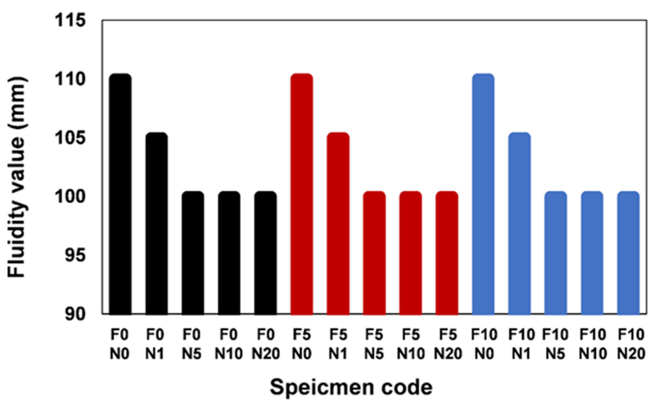
3.1. Fluidity Characteristic

Figure 2 presents fluidity of each specimen manufactured according to the mix proportion. The flowability test of fresh-state mixtures was carried out based on the specification provided in the ASTM C 1437. As the amount of MWCNTs increased, the fluidity of all specimens decreased, and this phenomenon was remarkable as the amount of MWCNTs increased. However, regardless of the presence or not of CFs, the flow characteristics of each specimen were similar. Hence, it is considered that the influence of the CFs content on the flow was insignificant.
As mentioned in previous literatures [9,23], the electrical conductivity properties of the cement composite incorporating MWCNTs are dependent on the fluidity of the paste, and it was reported that the resistance of the material decreases when the flowability decreases in general [9]. In addition, the average fluidity value of the specimen was fixed at 105 ± 5 mm, based on the previous study that the dispersion of the MWCNTs filler was greatly limited when the fluidity exceeded 120 mm.

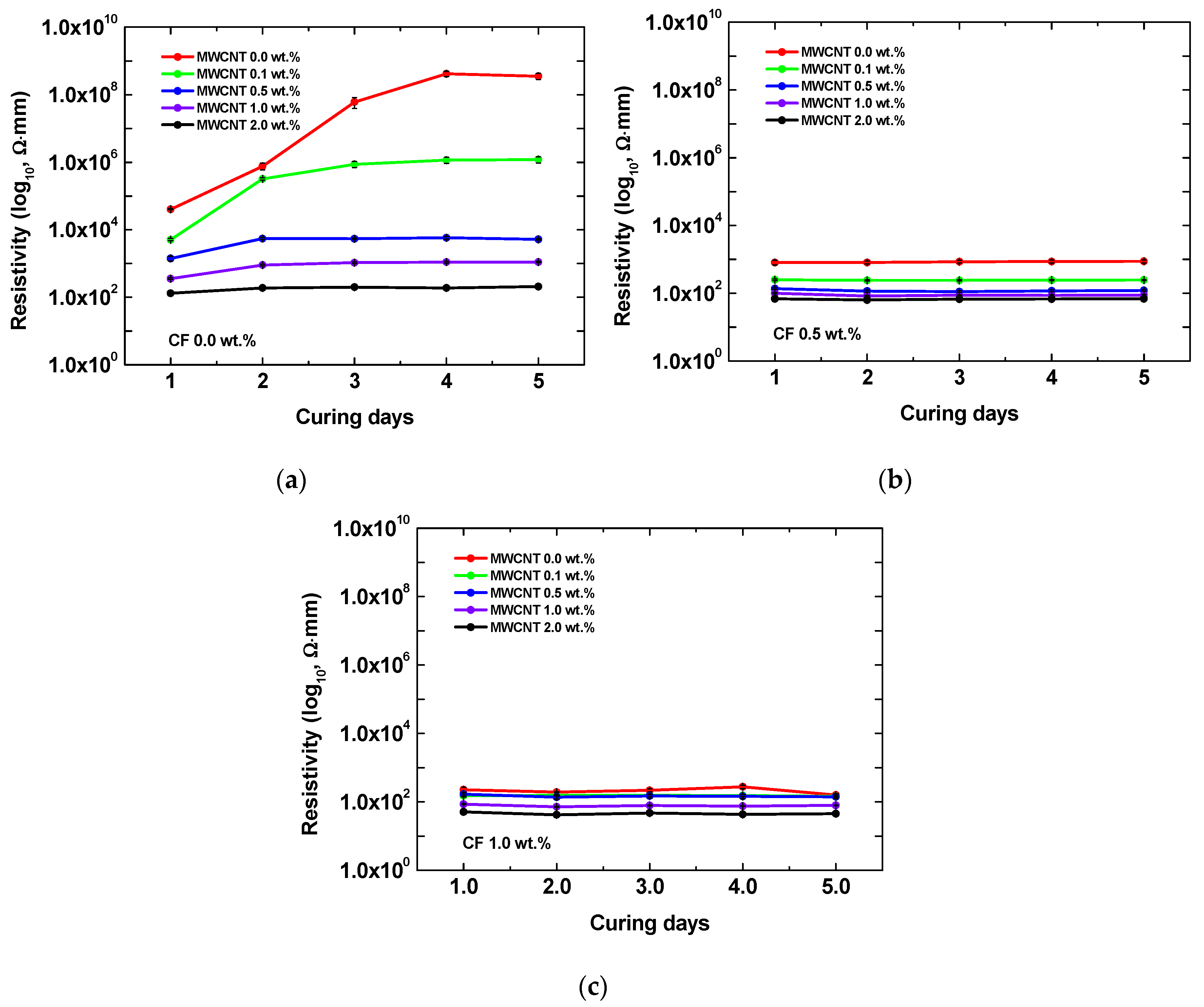
3.2. Electrical Resistivity

The measured electrical resistivity of the AAS composite is summarized in Figure 3. Overall, increasing of MWCNTs content causes a reduction of electrical resistivity. For the MWCNTs, the addition of more than 0.5 wt.%, known as the percolation threshold of the nanofiller-incorporated cementitious composite, the range of resistivity reduction was dramatically reduced. For the specimens containing both MWCNTs and CFs, it can be observed in Figure 3b,c that the electrical characteristics of the AAS composites significantly improved. In particular, in the curing age of 28 days, the electrical resistivity value of specimen with CFs of 0.5 wt.% considerably decreased compared to the specimen with no CF additive. The reduction of electrical resistivity value was caused by the bridge phenomenon of the conductive pathway between MWCNTs and CFs.

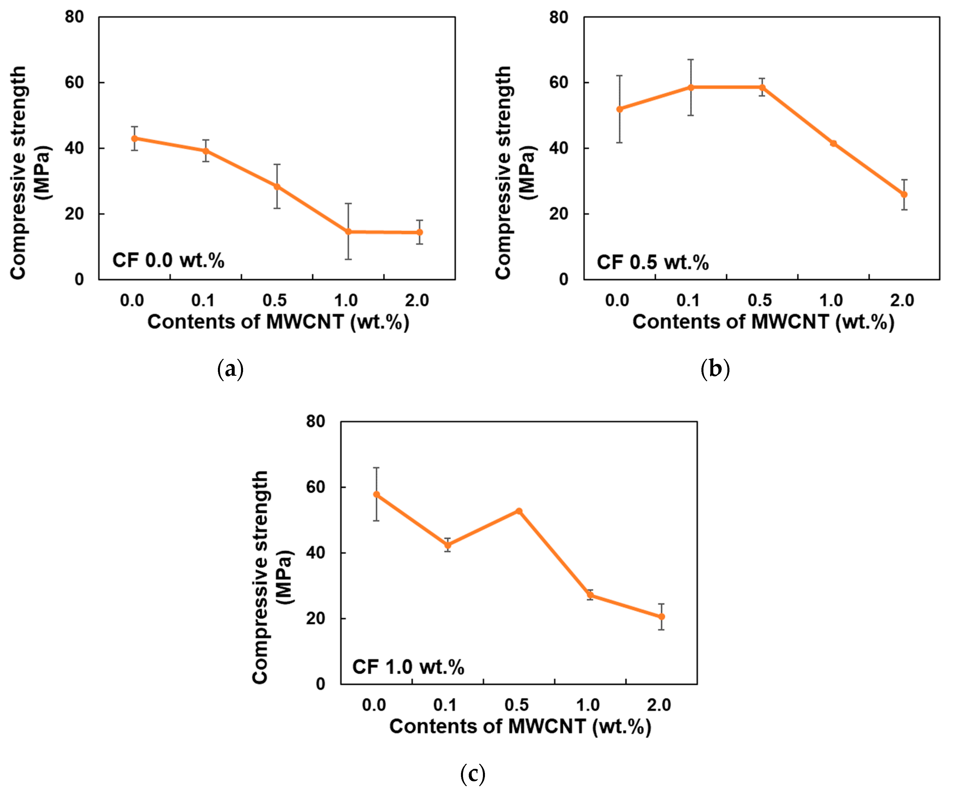
3.3. Compressive Strength

The compressive strength results of AAS composite are summarized in Figure 4. As a result, the increase of MWCNTs content was a decreased compressive strength of AAS composite, regardless of the CFs contents. However, the strength of AAS composite with MWCNTs 0.0 wt.%, i.e., the specimen containing only CFs, was slightly increased with the increase of CFs content. When the cracks reach the CFs, the crack propagates through the connection between fiber and the AAS matrix. In other words, the crack is deflected depending on the interaction of the branched crack and fiber.
The compressive strength slightly increased while the MWCNTs content rose from 0.0 to 0.5 wt.%, as shown in Figure 4b. Such an increase in compressive strength caused by the addition of nanofiller possibly attributed to the interaction between filler and matrix, which can happen when MWCNTs have good dispersibility. Moreover, it is verified that MWCNTs in that specimen were well dispersed in a range of 0.0 to 0.5 wt.%. However, when MWCNTs were added in excess of the 0.5 wt.%, the strength decreased significantly, as shown in Figure 4b,c. It was caused by agglomeration of MWCNTs filler, generated when nanofiller of an excessive amount more than the percolation threshold value (>0.5 wt.%) was added.

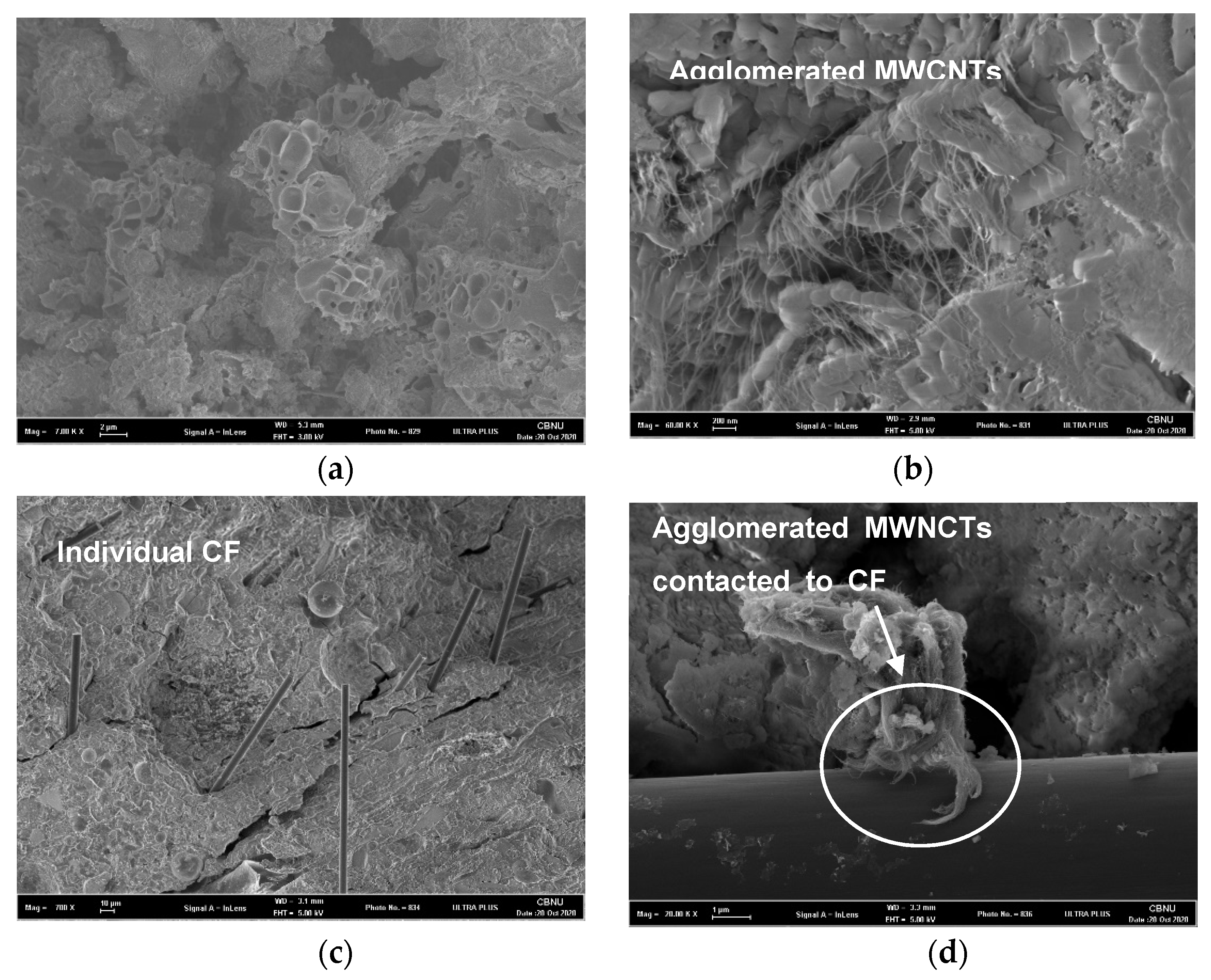
3.4. Synergistic Effect of MWCNTs and CFs Hybrid Fillers

SEM micrographs of AAS composite incorporating MWCNTs and CFs are presented in Figure 5. The representative hydrate products of AAS, calcium alumina silicate hydrate (CASH), can be seen in Figure 5a. Figure 5b shows agglomerated MWCNTs observed in the F0N10 specimen [24]. An excessive content of MWCNTs interfered with the uniform dispersion of the filler inside the AAS binder, leading the MWCNTs agglomeration, was observed. In addition, there was a large number of small-sized pores existing inside the MWCNTs agglomeration. It is believed that these pores are susceptible to deformation due to hydrate formation and cause high resistance change over time (Figure 3a) [21,26]. These pores adversely affect the hydration of the AAS binder and negatively affect the compressive strength (Figure 4).
Meanwhile, Figure 5c shows the SEM image of the CFs distributed within the AAS binder. Unlike the MWCNT, CF, which is a macro size, could not find an aggregation phenomenon, and it was properly dispersed. The contact phenomenon between MWCNTs and CFs filler is shown in Figure 5d. It is believed that the connection of two fillers causes a bridging effect in a AAS matrix, and it induces the formation of uniform conductive network [22]. The electrically conductive path of the AAS composites is susceptible to damage due to hydration and external impact, which in turn causes instability of electrical properties. The combination of MWCNTs and CFs filler implements nano- and micro-sized multiscale conductive pathways, and enables more stable and improved electrical properties. It is concluded that the small change in resistivity, over time, of the specimens containing CFs, is due to this bridging effect (shown in Figure 3) [22].
The TG and the derivative TG (DTG) results of the AAS composite are shown in Figure 6. Herein, only specimens for F0N0, F0N10, F10N0, and F10N10 were analyzed to investigate the effect of MWCNTs and CFs on the AAS composites. All samples clearly showed DTG peaks at the ranges of 100–200 °C and 450–600 °C. The weight loss hump seen over a temperature below 200 °C is due to the evaporation of free and physically attached water molecules from the binder gel [27]. Incorporating MWCNTs or CFs led to a notable increase in the weight loss below 200 °C, indicating a higher degree of hydration in these samples. This can be attributed to the filler effect, which enhances reaction of raw materials [23,28,29].

4. Conclusions

In the present study, the various characteristics of hybrid filler-incorporated AAS composites were studied. The specimens with different mix proportions were fabricated in the present study, and MWCNTs and CFs content were designed based on a previous study. The AAS composites were characterized through the flowability, electrical, and mechanical property tests, and were investigated via microstructural analysis. The main findings in this study can be summarized as: (1) the added MWCNTs absorbed the water molecules inside the AAS binder, and ultimately reduced the initial flowability of the AAS composites; and (2) overall specimen; reduction of electrical resistivity arose (as increasing of MWCNTs content). In particular, simultaneous adding of MWCNTs and CFs induces the bridging effect and significantly reduces the electrical resistivity. In order to analyze the mechanical properties more precisely, the measurement of porosity should be additionally performed. However, due to the limitations of the research environment, the experimental results were not included in this paper.
Overall, it was found that the 0.5 wt.% of MWCNTs and CFs lead the effects of the bridging and reducing crack propagation, thereby improving its electrical and mechanical performances. The filler, exceeding a percolation point, improved the electrical performance of the AAS composites. The proposed study aimed to evaluate the mechanical and electrical properties of AAC by mixing MWCNTs and CFs. In order to match the flow value, different amounts of activators were utilized for each formulation. However, it acted as a factor, leading difficulties in analyzing the effect of the conductive fillers on the composites. It is an experimental limitation of the present research, and future studies will proceed in the direction of applying the same amount of activator.

Author Contributions

Conceptualization, H.M.P. and B.Y.; methodology, C.P.; formal analysis, H.M.P. investigation, M.L.; resources, M.L.; writing—original draft preparation, H.M.P. and J.B.; writing—review and editing, B.Y. and M.L. All authors have read and agreed to the published version of the manuscript.

Funding

This research was supported and funded by the Korean National Police Agency. [Project Name: Development of on-site support equipment for criminal safety arrest/Project Number: PR08-01-000-20]. In addition, this work was supported by the National Research Foundation of Korea (NRF) grant funded by the Korea government (MSIT) (2020R1C1C1005063).

Conflicts of Interest

The authors declare no conflict of interest.

References

  1. Mehta, K.P. Reducing the environmental impact of concrete. Concr. Int. 2001, 23, 61–66. [Google Scholar]
  2. Dong, K.; Jiang, H.; Sun, R.; Dong, X. Driving forces and mitigation potential of global CO2 emissions from 1980 through 2030: Evidence from countries with different income levels. Sci. Total Environ. 2019, 649, 335–343. [Google Scholar] [CrossRef] [PubMed]
  3. Lee, N.K.; Lee, H.K. Setting and mechanical properties of alkali-activated fly ash/slag concrete manufactured at room temperature. Constr. Build. Mater. 2013, 47, 1201–1209. [Google Scholar] [CrossRef]
  4. Lee, N.K.; Kim, H.K.; Park, I.S.; Lee, H.K. Alkali-activated, cementless, controlled low-strength materials (CLSM) utilizing industrial by-products. Constr. Build. Mater. 2013, 49, 738–746. [Google Scholar] [CrossRef]
  5. Lee, N.K.; Jang, J.G.; Lee, H.K. Shrinkage characteristics of alkali-activated fly ash/slag paste and mortar at early ages. Cem. Concr. Compos. 2014, 53, 239–248. [Google Scholar] [CrossRef]
  6. Kim, G.M.; Nam, I.W.; Yoon, H.N.; Lee, H.K. Effect of superplasticizer type and siliceous materials on the dispersion of carbon nanotube in cementitious composites. Compos. Struct. 2018, 185, 264–272. [Google Scholar] [CrossRef]
  7. Nam, I.W.; Kim, H.K.; Lee, H.K. Influence of silica fume additions on electromagnetic interference shielding effectiveness of multi-walled carbon nanotube/cement composites. Constr. Build. Mater. 2012, 30, 480–487. [Google Scholar] [CrossRef]
  8. Kim, H.K.; Nam, I.W.; Lee, H.K. Enhanced effect of carbon nanotube on mechanical and electrical properties of cement composites by incorporation of silica fume. Compos. Struct. 2014, 107, 60–69. [Google Scholar] [CrossRef]
  9. Park, H.M.; Kim, G.M.; Lee, S.Y.; Jeon, H.; Kim, S.Y.; Kim, M.; Kim, J.W.; Jung, Y.C.; Yang, B.J. Electrical resistivity reduction with pitch-based carbon fiber into multi-walled carbon nanotube (MWCNT)-embedded cement composites. Constr. Build. Mater. 2018, 165, 484–493. [Google Scholar] [CrossRef]
  10. Yim, Y.J.; Heo, Y.J.; Park, S.J. Effect of electroless nickel plating on electromagnetic interference shielding effectiveness of pitch-based carbon papers/epoxy composites. Func. Compos. Struct. 2019, 1, 035001. [Google Scholar] [CrossRef]
  11. Cho, J.; Jang, H.G.; Kim, S.Y.; Yang, B. Flexible and coatable insulating silica aerogel/polyurethane composites via soft segment control. Compos. Sci. Technol. 2019, 171, 244–251. [Google Scholar] [CrossRef]
  12. Jung, Y.T.; Roh, H.D.; Lee, I.Y.; Park, Y.B. Strain sensing and progressive failure monitoring of glass-fiber-reinforced composites using percolated carbon nanotube networks. Func. Compos. Struct. 2020, 2, 015006. [Google Scholar] [CrossRef]
  13. Kim, S.Y.; Jang, J.U.; Haile, B.F.; Lee, M.W.; Yang, B. Swarm intelligence integrated micromechanical model to investigate thermal conductivity of multi-walled carbon nanotube-embedded cyclic butylene terephthalate thermoplastic nanocomposites. Compos. Part A App. Sci. Manuf. 2020, 128, 105646. [Google Scholar] [CrossRef]
  14. Ghosh, S.; Harish, S.; Rocky, K.A.; Ohtaki, M.; Saha, B.B. Graphene enhanced thermoelectric properties of cement based composites for building energy harvesting. Energ. Build. 2019, 202, 109419. [Google Scholar] [CrossRef]
  15. Cai, J.; Tan, J.; Li, X. Thermoelectric behaviors of fly ash and metakaolin based geopolymer. Constr. Build. Mater. 2020, 237, 117757. [Google Scholar] [CrossRef]
  16. Douglas, E.; Bilodeau, A.; Malhotra, V.M. Properties and durability of alkali-activated slag concrete. Mater. J. 1992, 89, 509–516. [Google Scholar]
  17. Collins, F.G.; Sanjayan, J.G. Workability and mechanical properties of alkali activated slag concrete. Cem. Concr. Res. 1999, 29, 455–458. [Google Scholar] [CrossRef]
  18. Yang, B.J.; Jang, J.G. Environmentally benign production of one-part alkali-activated slag with calcined oyster shell as an activator. Constr. Build. Mater. 2020, 257, 119552. [Google Scholar] [CrossRef]
  19. Talling, B.; Brandstetr, J. Present state and future of alkali-activated slag concretes. Am. Concr. Inst. 1989, 114, 1519–1546. [Google Scholar]
  20. Bakharev, T.; Sanjayan, J.G.; Cheng, Y.B. Sulfate attack on alkali-activated slag concrete. Cem. Concr. Res. 2002, 32, 211–216. [Google Scholar] [CrossRef]
  21. Kim, G.M.; Nam, I.W.; Yang, B.; Yoon, H.N.; Lee, H.K.; Park, S. Carbon nanotube (CNT) incorporated cementitious composites for functional construction materials: The state of the art. Compos. Struct. 2019, 227, 111244. [Google Scholar] [CrossRef]
  22. Kim, G.M.; Yang, B.J.; Yoon, H.N.; Lee, H.K. Synergistic effects of carbon nanotubes and carbon fibers on heat generation and electrical characteristics of cementitious composites. Carbon 2018, 134, 283–292. [Google Scholar] [CrossRef]
  23. Kim, G.M.; Park, S.M.; Ryu, G.U.; Lee, H.K. Electrical characteristics of hierarchical conductive pathways in cementitious composites incorporating CNT and carbon fiber. Cem. Concr. Compos. 2017, 82, 165–175. [Google Scholar] [CrossRef]
  24. Park, H.M.; Park, S.M.; Lee, S.M.; Shon, I.J.; Jeon, H.; Yang, B.J. Automated generation of carbon nanotube morphology in cement composite via data-driven approaches. Compos. Part B Eng. 2019, 167, 51–62. [Google Scholar] [CrossRef]
  25. Cho, J.; Lee, S.K.; Eem, S.H.; Jang, J.G.; Yang, B. Enhanced mechanical and thermal properties of carbon fiber-reinforced thermoplastic polyketone composites. Compos. Part A App. Sci. Manuf. 2019, 126, 105599. [Google Scholar] [CrossRef]
  26. Yang, B.J.; Cho, K.J.; Kim, G.M.; Lee, H.K. Effect of CNT agglomeration on the electrical conductivity and percolation threshold of nanocomposites: A micromechanics-based approach. CMES-Comput. Model. Eng. Sci. 2014, 103, 343–365. [Google Scholar]
  27. Park, S.; Yoon, H.N.; Seo, J.; Lee, H.K.; Jang, J.G. Structural evolution of binder gel in alkali-activated cements exposed to electrically accelerated leaching conditions. J. Hazard. Mater. 2020, 387, 121825. [Google Scholar] [CrossRef]
  28. Popescu, M.A.; Isopescu, R.; Matei, C.; Fagarasan, G.; Plesu, V. Thermal decomposition of calcium carbonate polymorphs precipitated in the presence of ammonia and alkylamines. Adv. Powder Technol. 2014, 25, 500–507. [Google Scholar] [CrossRef]
  29. Park, S.; Park, H.M.; Yoon, H.N.; Seo, J.; Yang, C.M.; Provis, J.L.; Yang, B. Hydration kinetics and products of MgO-activated blast furnace slag. Constr. Build. Mater. 2020, 249, 118700. [Google Scholar] [CrossRef]
Figure 1. (a) Image of the alkali-activated slag (AAS) composite used in this study and (b) layout of the AAS composite specimen containing both multi-walled carbon nanotubes (MWCNTs) and carbon fibers (CFs).
Crystals 10 01139 g001
Figure 2. Fluidity values of alkali-activated slag (AAS) composites.
Crystals 10 01139 g002
Figure 3. Electrical resistivity results of MWCNTs-incorporated AAS composites with (a) 0 wt.%, (b) 0.5 wt.%, and (c) 1.0 wt.% of CF according to the curing days.
Crystals 10 01139 g003
Figure 4. Compressive strength results of CF filler-incorporated AAS composites with (a) 0 wt.%, (b) 0.5 wt.%, and (c) 1.0 wt.% of CF.
Crystals 10 01139 g004
Figure 5. SEM micrograph images of (a) F0N0, (b) F0N10, (c) F10N0, and (d) F10N10 specimens.
Crystals 10 01139 g005
Figure 6. Results of thermal analyses of AAS specimens: (a) Thermogravimetric (TG) and (b) derivative TG (DTG).
Crystals 10 01139 g006
Table 1. Chemical compositions of the ground granulated blast-furnace slag (GGBS) and fly ash obtained by X-ray fluorescence (wt.%).
CaOSiO2Al2O3Fe2O3MgONa2OK2OSO3TiO2Mn2O3SrOLOI *
Fly ash4.857.021.010.01.3-1.41.01.5--2.7
Slag44.833.513.70.52.90.20.51.70.50.20.11.4
* LOI: Limiting oxygen index.
Table 2. Mix proportion of alkaline activator used in the present study (g).
Ms
(SiO2/Na2O)
WaterSodium Hydroxide
(NaOH)
Sodium Silicate
(Na2SiO3)
1.11000160580
Table 3. Mix proportion of electrified alkali-activated slag mortar to be used for the present study (wt.%).
SpecimenSlagFly AshCFMWCNTAlkali ActivatorFlow
(mm)
F0N050500.00.045105 ± 5
F0N10.150
F0N50.552.5
F0N101.062.5
F0N202.075
F5N00.50.045
F5N10.150
F5N50.552.5
F5N101.062.5
F5N202.075
F10N01.00.045
F10N10.150
F10N50.552.5
F10N101.062.5
F10N202.075
Publisher’s Note: MDPI stays neutral with regard to jurisdictional claims in published maps and institutional affiliations.

