A Stress Orientation Analysis Framework for Dislocation Glide in Face-Centred Cubic Metals


Department of Materials Science and Metallurgy, University of Cambridge, 27 Charles Babbage Rd, Cambridge CB3 0FS, UK
*
Author to whom correspondence should be addressed.
Crystals 2020, 10(6), 445; https://0-doi-org.brum.beds.ac.uk/10.3390/cryst10060445
Submission received: 3 May 2020
/
Revised: 27 May 2020
/
Accepted: 28 May 2020
/
Published: 30 May 2020
Abstract
:Plastic deformation in metals is heavily influenced by the loading direction. Studies have explored its effects on multiple mechanisms by analysing individual dislocations, but there is currently no systematic way of rationalising the cooperative behaviour of the different slip systems for arbitrary stress tensors. The current study constitutes the foundation of a new orientation analysis framework for face-centred cubic crystals by introducing “stress orientation maps”, graphical tools to simultaneously analyse the effects of loading orientation on the stress state of the and slip systems in a comprehensive, yet intuitive way. Relationships between the Schmid and Escaig stresses are described from geometrical constraints of the slip systems in the crystal structure, linking the dislocation behaviour on a slip plane with the stress tensor via a one parameter description. The case of uniaxial loading along different orientations within the fundamental sector of the unit cell is explored to describe the physical basis, properties and capabilities of this framework. The stress normal to the slip plane is then considered in the analysis via an extension of the Mohr’s circles. The orientation dependence of two twin nucleation mechanisms from the literature are examined as examples of how the stress orientation maps can be used.
1. Introduction
Historically, little attention has been paid to the effect of non-Schmid stresses on various dislocation mechanisms in face-centred cubic (fcc) crystals. While the Schmid stress dictates for the most part the glide behaviour of a dislocation, it has been shown across different length scales that the Escaig stress (also referred to as co-slip stress) and the normal stress play crucial roles in phenomena such as stacking fault constriction [1], homogeneous and heterogeneous dislocation nucleation [2,3,4], dislocation drag [5,6], stacking fault propagation [7], superlattice stacking fault propagation [8] and cross slip [9,10,11]. Because of how diverse these mechanisms are, these stresses have been analysed using different arbitrary nomenclatures and coordinate systems, which makes it difficult to transfer these concepts across different areas of study.
The Escaig stress in particular has been ignored in many cases. This is the stress resolved on the slip plane of a given dislocation but in the direction perpendicular to its Burgers vector [9], such that it exerts no force on it. However, for a dissociated dislocation, the Escaig stress pushes both Shockley partials with the same force but in opposite directions, thereby expanding or contracting the intrinsic stacking fault width. Its effect on the separation between the partials is small in materials with a high stacking fault energy, and considering that most fcc engineering alloys used during the first half of the 20th century fall into this category, it is understandable that the Escaig stress was ignored in most early metallurgical studies. However, it has a big influence on low stacking fault energy materials, such as austenitic stainless steels, nickel-based superalloys and advanced TWIP and TRIP steels, in which formation of extended stacking faults is promoted with shear stresses as low as 250 MPa [12]. Thus, it is necessary to account for its effect in any stress activated mechanism that is affected by a change in the stacking fault width.
The normal stress affects the atomic structure by effectively changing the spacing between parallel planes. This has a direct effect on the Peierls stress, with lower resistances for higher compressive stresses [6]. This stress component has also been shown to affect the onset of dislocation nucleation [2,3,4], which becomes critical for the activation of multiple deformation mechanisms. The well known relation between normal and shear stresses in the form of the Mohr’s circles describes the possible combinations that may result on any given plane for a given stress state. Nevertheless, this does not account for crystallographic features or individual slip systems.
Previous research in the relevant areas of plasticity affected by non-Schmid stresses has been mostly carried out with the use of molecular dynamics and line tension approximations performed at the nanoscale on individual slip systems (e.g., references [2,5,13] and [1,10,11,14], respectively). Whilst these improve our understanding of the mechanisms involved, there is no systematic way of translating these results into orientation-dependent macroscopic effects for different reasons. When imposing a stress state onto one slip system to study a mechanism, dislocations on other slip systems will experience resolved stresses that may promote completely different behaviours. Consider the difficulty in assessing what forces all the dislocations experience even for simple loading conditions. For any given stress tensor with shear components, it is typically hard tracking what the values of the relevant resolved shear stresses on each slip system are and there is virtually no way of visualising them other than by tabulating them. For more complicated mechanisms that involve reactions between dissimilar dislocations, it becomes increasingly difficult determining which applied loads will promote their occurrence. Moreover, criteria for the appearance of some mechanisms are often proposed purely based on the competition between different dislocation behaviours, promoting the one with the lowest critical resolved shear stress, which if orientation-dependent, is hard to assess.
The current work addresses these issues by developing a stress orientation analysis framework based upon a simple concept: all three coplanar Schmid and Escaig stresses on each slip system are linked to each other due to simple geometrical constraints of the fcc structure. This concept is used in Section 2 to introduce a new intuitive graphical representation of the stress states on the individual slip systems that facilitates the understanding of stress orientation effects and enables more comprehensive studies of orientation-dependent deformation mechanisms. Two twin nucleation criteria widely used in the literature are then studied in Section 3 using the new framework to showcase its capabilities.
2. Stress Orientation Framework
Following the setup adopted by Baudouin et al. [12], consider an orthonormal right-handed coordinate system oriented with respect to a dislocation so that the x-axis coincides with its Burgers vector and the z-axis is perpendicular to its slip plane. The angle between the Burgers vector and the line vector dictates the character of the dislocation, ranging from (screw segment) to (edge segment). If the dislocation dissociates into Shockley partials, their Burgers vectors will point at angles of from . For such a dissociated dislocation viewed from outside Thompson’s tetrahedron, an intrinsic stacking fault is achieved by placing the partials in a specific order [15,16], in this case given by and , where the subindices and refer to the leading and trailing partials, respectively. Figure 1 shows the arrangement proposed for such a dislocation and its Shockley partials.
Under a homogeneous stress field within this coordinate system with the general form
glide of a perfect dislocation depends only on the magnitude of the Schmid stress , and occurs in the direction (if it is positive). For a remote stress , the Peach–Koehler equation from linear isotropic elasticity theory predicts a force on the dislocation with magnitude and direction perpendicular to . In this scenario, none of the other stress components affect the evolution of the dislocation. However, if we consider a dissociated dislocation, then will exert forces with the same magnitude but in opposite direction on both partials. The resulting forces in this case are
where is the Escaig stress. Note that the sum of both forces adds up to the force felt by the perfect dislocation; i.e., .
The importance of the Escaig stress comes into play when analysing its effect on the stacking fault width. Consider an infinitely long straight dislocation dissociated into partials in a frictionless and otherwise perfect fcc crystal. Other than the forces from the remote stress, the partials will also experience attraction due to the stacking fault binding them together and repulsion due to the interaction force between them. The total forces per unit length felt by the partials in the direction perpendicular to their line vectors are
where is the interaction force [12],
d is the intrinsic stacking fault width, G is the shear modulus, is the Burgers vector of a partial dislocation, is the Poisson’s ratio and is the intrinsic stacking fault energy. If there is no stress applied, a stable separation distance between the partials is predicted.
If the stress applied is non-zero, the force balance gives a new stable stacking fault width [12]
A positive Escaig stress will thus reduce the separation between the partials and the stacking fault width will extend to infinity whenever . Note that in the literature the Escaig stress is often defined in the opposite way (so that a positive increases d), but the orientation chosen in this work matches that of the more widely used Thompson’s notation.
Following a very similar analysis, Byun [7] reported that the stacking fault width will never vary for an edge dislocation, although he made a crucial mistake by completely ignoring any stress contribution in the direction of the line vector. Even though Equation (5) was published half a decade ago [12], Byun’s character dependence is still widely and incorrectly used as an assumption in stacking fault and twinning analyses [17,18]. In reality, linear isotropic elasticity predicts the stacking fault width of an edge segment to be larger than that of a screw by a factor of ( for a typical value of ) and the complete decorrelation of the partials to occur at the same stress for any dislocation character.
For the next part of the analysis, consider a plot of vs. in which the stress state of all the slip systems are included, hereby denoted "stress orientation maps." Due to the high symmetry of the fcc unit cell, there are two geometrical constraints on the coordinates of the twelve points, regardless of the stress tensor. Firstly, the three slip systems of each plane fall within a circle of radius centred at the origin, where is the unit vector normal to the slip plane. Secondly, the points in each circle are spaced apart just like the three coplanar Burgers vectors. Figure 2a shows some of these maps for the case of uniaxial tensile loading considering both the Schmid factor and an analogous Escaig factor , where is the magnitude of the applied tensile stress. Note that in some plots, such as those for the vertices of the inverse pole figure, two or more points share the same coordinates. It must be emphasised that these maps are not stereographic projections of any kind, but geometric representations of the stresses on all the slip planes.
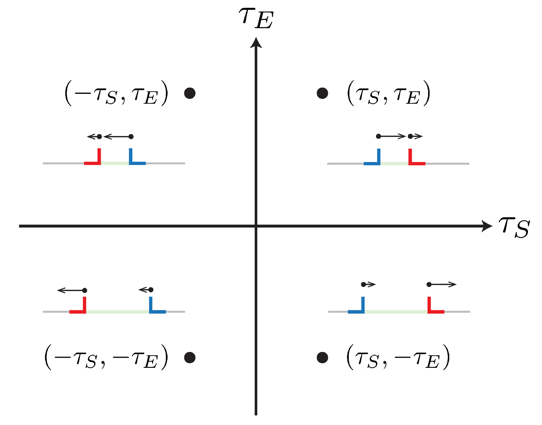
Consider two dissociated dislocations with stress states at points and , as those in Figure 3. A negative Schmid stress reverses the direction of motion of a dislocation and swaps the leading with the trailing partial, but leaves the stacking fault width unchanged. Thus, a map with the absolute value is sufficient to represent the behaviour of the 12 slip systems, as shown in Figure 2b,c.
Compare now the first stress state proposed with that which arises upon loading reversal, i.e., , from Figure 3. In this case, both the direction of motion of the dislocation and the effect of the Escaig stress on the stacking fault width are reverted. This effect most likely has an effect during cyclic loading, as it implies that partials will glide with a different separation during, for instance, tensile and compressive stages; one of them is more likely to cross slip. Graphically, a stress reversal results in a point inversion around the origin. Thus, it can immediately be seen that the deformation behaviour of crystals loaded in tension along a or direction will resemble that of one compressed along a axis.
These maps also allow for a quick inspection of the stress state in each partial, a description preferred by some authors [17,19]. The Burgers vectors of the leading and trailing partials were initially chosen to point at and from the x-axis, and these constraints are preserved in the stress orientation maps. The Schmid factors of the partials that compose each perfect dislocation, and , are the projections onto axes that point at these angles. Note that the lines joining the point with the highest Schmid factor and the two coplanar slip directions have in the orientation map slopes of , as they share the same partials. Similarly, the polar coordinates (with radius m and angle ) for each slip system can be easily observed; this description is also widely used in the literature [20,21,22]. Table 1 contains the conversion formulae between the variables from different nomenclatures.
A map such as that in Figure 2c can be further divided into three regions within the intervals , and . Due to the geometrical constraints of the slip systems, the stress states in the outer regions of the map can be linked to those in the central region by mirror operations along axes pointing at and (blue lines in Figure 2c). A map with the central region only, such as that in Figure 2d, simultaneously captures the stress state of every and slip system in the crystal in a unique and unambiguous manner. Moreover, the stress orientation of a whole slip plane can be defined by the angle (marked in red in Figure 2c) of the stress state within this domain; i.e., .
This result is of great value as it relates the resolved shear stresses with whole crystal orientations. A deformation mechanism may be studied on an individual slip system, but fully understanding its dependence on crystal orientation requires simultaneously analysing the stress states of all slip systems to determine whether it is promoted or not in the material. Regions for the appearance of such plasticity mechanisms can be drawn in full stress orientation maps and then translated into the domain of (as further explained in Section 3).
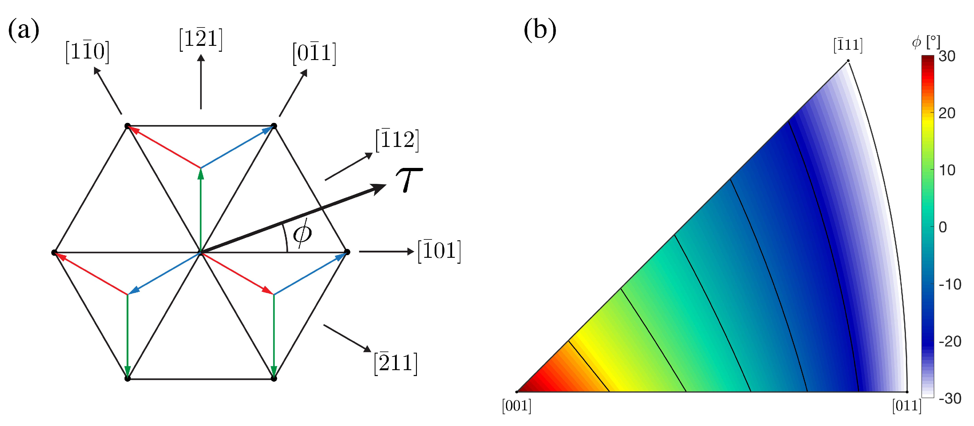
Physically, an angle favours glide of the same leading partial in two coplanar slip systems and appears on the plane with the highest shear stress during tensile loading along an orientation on the line from to or upon compression. Alternatively, results in a higher Schmid factor for the trailing partial also on two coplanar slip systems. The transition when moving away from a axis occurs as the stress state on the slip plane rotates between two consecutive directions because of the specific routes the atoms must take in order to generate an intrinsic stacking fault, illustrated in Figure 4a. This fundamental difference between the two types of directions in an fcc crystal must be incorporated into any type of mechanistic modelling driven by Shockley partials, but is often ignored [23,24]. Figure 4b shows the value of for the slip plane with the highest Schmid factor for all possible uniaxial tensile loading orientations. This angle is then a more intuitive parameter than others found in the literature to account for the stress orientation on an octahedral plane.
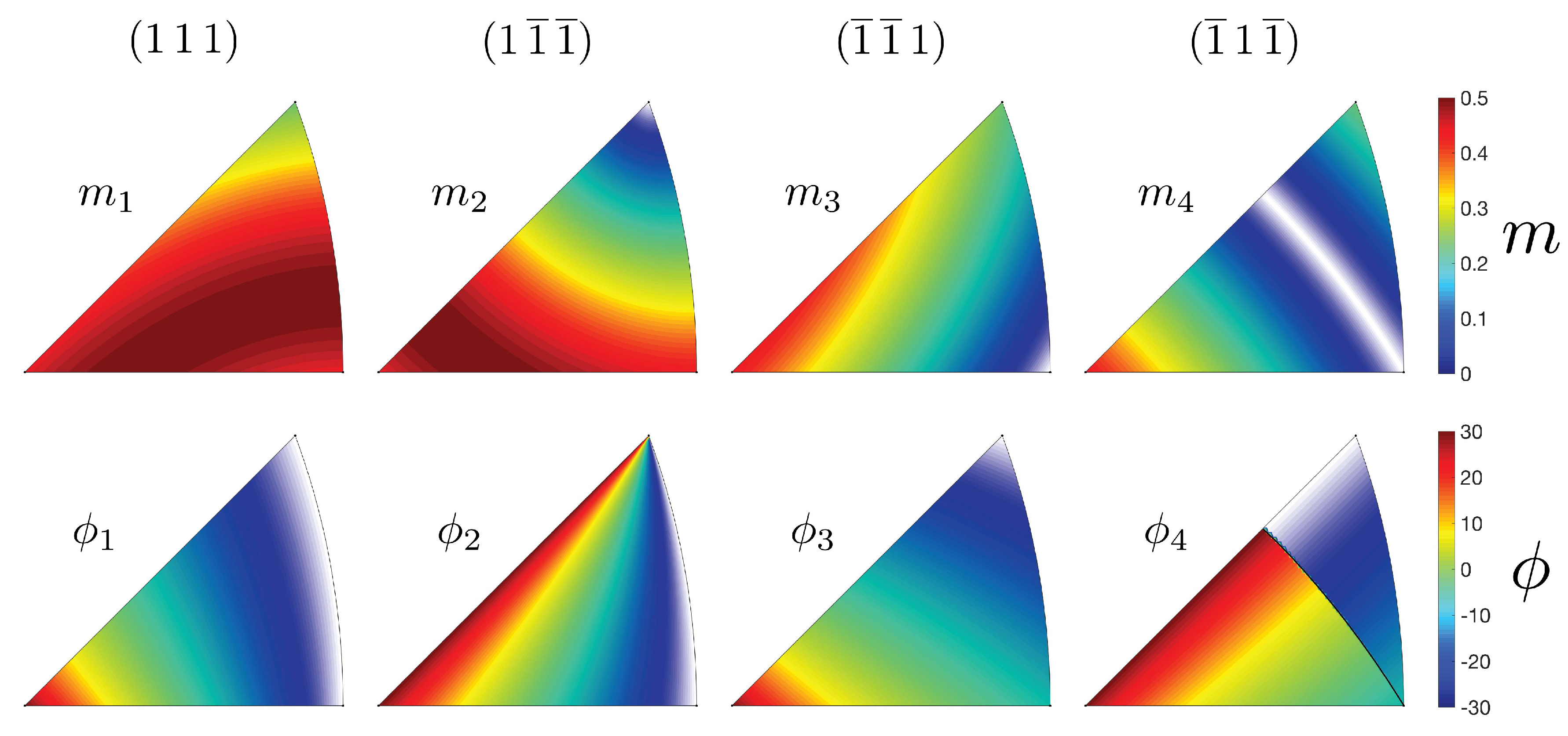
The previous description can also be extended to the four slip planes; the corresponding values and angles are plotted in Figure 5. This clearly shows that the shear stress on the different slip planes may have different effects under some loading orientations, possibly promoting different mechanisms. Together with the stress orientation maps, this description may be used to determine the effects of stress orientation on the microscopic dislocation behaviour and the macroscopic deformation response.
Incorporating the stress normal to the slip plane , in the form of a normal factor , requires adding an extra dimension to the stress orientation maps. This makes the analysis less intuitive, but it may be necessary for studying phenomena where this stress plays an important role. A relation between the attainable shear and normal stresses already exists in the form of Mohr’s circles, which may be extended to include the decomposition of the former into the Schmid and Escaig components. Analogous Mohr’s spheres that intersect the axis at the eigenvalues of the stress tensor delimit the region where the stresses of the multiple slip systems can be located, either on their surfaces or in the space in-between them, while the aforementioned two-dimensional geometrical constraints are preserved in the orthogonal axes. Figure 6a,b show this geometrical representations for cases where two principal stresses have the same value and where all of them are different, respectively. The stress tensors are initially normalised by the difference between the maximum and minimum principal stresses to match the nomenclature used so far.
Potential applications of the introduced framework include the study of deformation mechanisms that involve Shockley partials, such as cross slip, superlattice stacking faults and Lomer–Cottrell locks, among others. The following section investigates the likelihood of two twin nucleation mechanisms to be promoted under uniaxial loading to as a simple example of how the introduced ideas can be put to work.
3. Deformation Twinning
Twinning in fcc alloys has been reported extensively in materials with a low stacking fault energy. This deformation mechanism accommodates plastic deformation by glide of partials with identical Burgers vectors on adjacent planes. A clear orientation dependence has been observed in single crystals and in individual grains in polycrystals. Uniaxial loading tests have shown that twinning is promoted close to a or orientation during tension [19,25,26,27,28,29,30] and during compression [29,31,32]; i.e., for orientations with a low value of on the slip plane with the highest resolved shear stress. Figure 4b is effectively the same as that in reference [33], where it is argued that the ratio is highly correlated to the likelihood of mechanical twins to develop. With the conversion formulae from Table 1, this is effectively . The use of angle facilitates the understanding of the orientation effects in each slip plane. A similar criterion is used by Cai et al. [32], although their ratio combines Schmid factors from slip planes in different slip systems.
This explains the propagation of twins for these orientations, but it remains unclear how they form in the first place. A realistic twin nucleation mechanism must account for the generation of identical Shockley partials on adjacent planes and for the immobilisation of the trailing partials if they exist. A number of twin nucleation mechanisms proposed have recently been summarised by De Cooman et al. [18]. The orientation dependencies of two of these, namely, the Copley–Kear–Byun and McCabe’s mechanisms, are analysed here under the light of the two-dimensional version of the orientation framework introduced as an example of how these concepts may be utilised. These two mechanisms were chosen due to the simplicity in the dislocations they involve, all of them being coplanar. However, this framework may also be useful in assessing the validity of more complex twin nucleation criteria, especially those that rely on non-coplanar dislocation reactions such as the Cohen–Weertman [34] and the Fujita–Mori [35] cross slip mechanisms.
3.1. Copley-Kear-Byun Mechanism
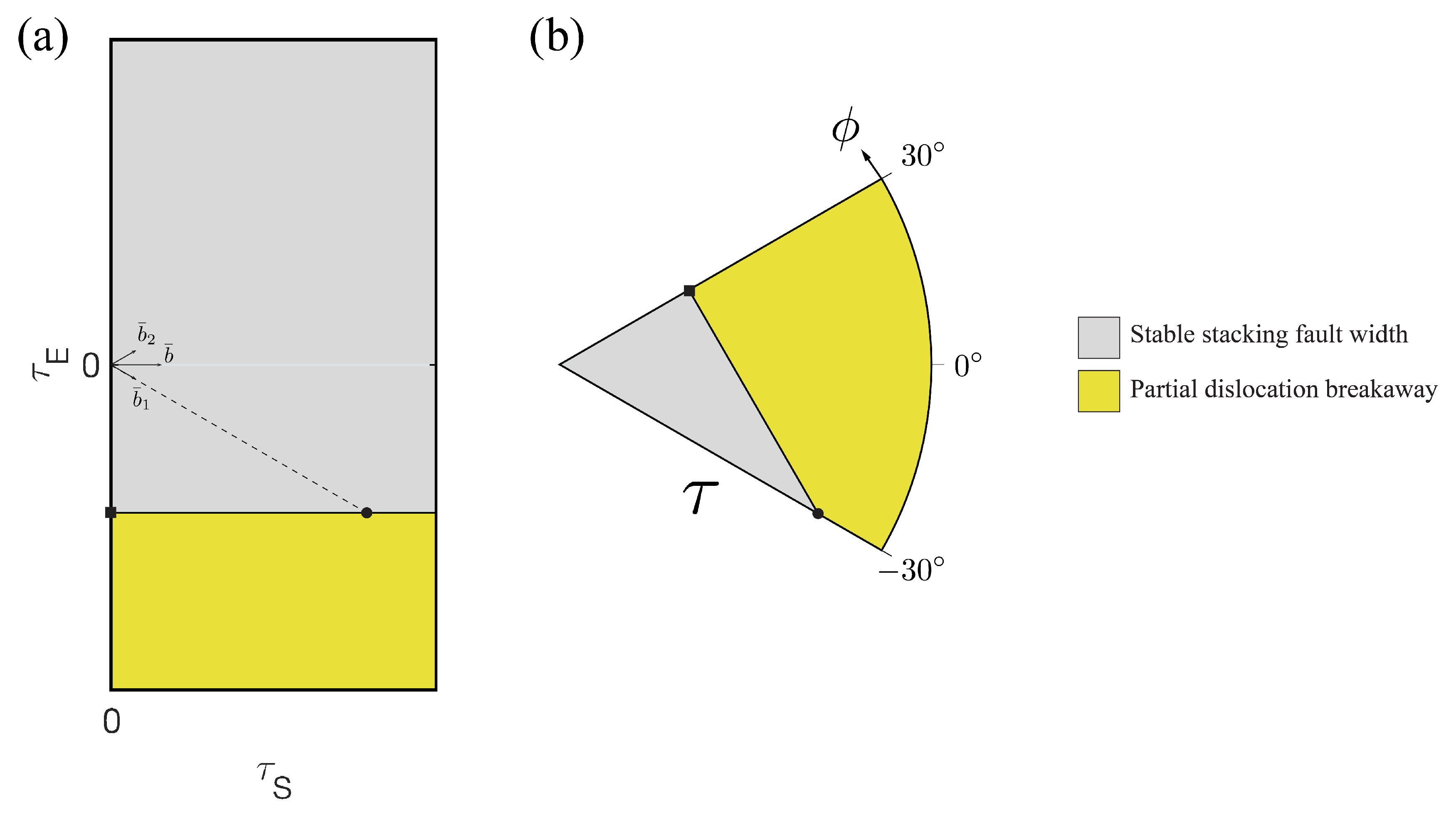
The Copley–Kear–Byun partial dislocation breakaway mechanism [7,36] has been proposed on the sole basis of stacking fault widening as a result of the stress applied. This can be thought of as generating an infinitely long stacking fault from Equation (5) with a large negative Escaig stress, and corresponds to the region highlighted in the mechanistic map in Figure 7a. The stress states of the multiple slip systems can be superimposed into this map to determine which ones will promote such mechanism. However, obtaining its full orientation dependence requires translating this analysis into the domain of . This is accomplished by performing a mirror operation of the boundary along the dashed line pointing at from the horizontal axis, resulting in the map shown in Figure 7b. This should not be read in terms of the actual stresses required to activate the mechanism, as it is clear that stresses at an angle are far from promoting twin nucleation. Instead, it means that if a stress state falls within the region highlighted, there will be a coplanar slip system (the one with the lowest Escaig factor) where the Copley–Kear–Byun mechanism is promoted. This is shown to require lower stresses for high values of , as a slip system located at an angle produces the largest separation of the partials. Twinning has been observed experimentally for the opposite configuration, deeming this mechanism unrealistic.
3.2. McCabe’s Twin Nucleation Criterion
Another twin nucleation mechanism that avoids introducing more complicated dislocation reactions is that proposed by Li et al. [37], where the required partials nucleate homogeneously. However, this would require very high stresses to occur. Instead, McCabe et al. [38] assumed that the partials can nucleate from grain boundaries in the following sequence. Initially, a leading partial is emitted and it glides away from its source. This is then followed by one of two options: (i) the emission of a trailing partial on the same slip plane, or (ii) the emission of another identical leading partial (denoted twinning partial) on an adjacent plane. The former results in perfect dislocation glide, whereas the latter forms an extrinsic stacking fault and later a twin if the process is repeated on adjacent planes. The criterion for twin nucleation is then that the driving force for nucleation of a twinning partial is greater than that for nucleation of a trailing partial.
Ignoring the image stresses near the grain boundary, the condition for nucleation of a leading partial reads
The forces on the dislocations to follow are
for a trailing partial and
for a twinning partial, where is the extrinsic stacking fault energy, the interaction force between a leading and a trailing partial and the interaction force between two leading partials. McCabe et al. [38] argued that the interaction forces are the same in both cases, which leads to the twin nucleation criterion
The graphical representation of this criterion is different in nature from that for the Copley-Kear-Byun mechanism, in which an already existing perfect dislocation may evolve into a twin nucleus. Instead, McCabe’s mechanism involves the competition between different dislocations, so that only the trailing partial with the highest Schmid factor must be considered. This means that the conditions in Equations (6) and (9) must be plotted only within the domain of , as shown in Figure 8 for an Fe-22 wt.% Mn-0.6 wt.% C polycrystalline TWIP steel ( mJ m, nm) [25], where the trailing partial with the highest resolved shear stress is that with a Burgers vector pointing at . It is clear that this mechanism is promoted for orientations closer to , which is supported by experimental evidence.
The minimum resolved shear stress that would promote twinning under these considerations is
for . In the case of uniaxial tension of the Fe-22 wt.% Mn-0.6 wt.% C TWIP steel [25], Equation (10) corresponds to a shear stress of 305 MPa. Considering only the remote stress, the grains expected to twin first under this criterion are those with the tensile axis parallel to a for a tensile stress of 647 MPa, which lies within the range where twin nucleation is observed. A complete description of the mechanism should also include other phenomena such as strain partitioning in the polycrystal, grain size effects [39,40] and the impact of on the energy barrier for dislocation nucleation [2,3,4]. These effects would invariably affect the critical shear stress required for twin nucleation. Nevertheless, the simplified approach followed here shows that McCabe’s criterion has an adequate stress orientation dependency for a crystal as a whole and this mechanism would likely still be viable for the right orientations if these effects were added to the model.
The difference in building the orientation dependencies of the Copley–Kear–Byun and McCabe’s mechanisms relies on the origin of the twin nucleus. In the former, pre-existing dislocations are able to evolve into a twin, which implies that a full stress map needs to be studied and then narrowed down to the domain of . In the latter, it is the competition between dissimilar Shockley partials which reduces the range of the analysis from the very beginning. Finally, the obtained orientation dependencies arise from performing a simultaneous analysis on the stress states of the slip systems on the primary slip plane based on the geometrical constraints of the crystal introduced in Section 2. This rules out the Copley–Kear–Byun criterion as a viable twin nucleation mechanism.
Note that the framework itself makes no assumptions as it is derived uniquely from the geometric constraints of the octahedral slip systems in an fcc crystal. Its application in the assessment of dislocation mechanisms relies upon physical models which themselves make the assumptions, and as such, it is these which must be scrutinised accordingly. For instance, both twin nucleation criteria studied here assume that there is a homogeneous stress state throughout the material, which in reality may vary considerably near grain boundaries [41] and other defects. McCabe’s model also considers that the interaction forces and have the same magnitude, which in reality can be shown to be false by calculating the Peach–Koehler forces between the dislocations involved. In reality, repulsion is higher for a twinning partial, which if taken into account would result in a higher critical stress for twin nucleation and a tilt in the horizontal boundary in Figure 8, although with a very similar orientation dependency.
Future work includes following a similar approach to describe the orientation dependencies of other dislocation mechanisms. Reactions that involve dissimilar dislocations can be benefited by the stress orientation maps as multiple stress states can be easily visualised in a single figure. Consider for instance the cross slip mechanism where both Schmid and Escaig stresses experienced by the dislocation on the primary and conjugate planes have an effect on the energy barrier [10,11,14], so that key pairs of stress states will favour this behaviour. Other potential uses of the orientation framework introduced here include the study of superlattice stacking fault propagation in nickel-based superalloys and more complex twin nucleation mechanisms. Moreover, the extension of this framework to other crystal structures may be possible accounting for the different types of slip systems they possess.
4. Conclusions
There exists a set of geometrical constraints that links the stresses that may be attained by the and slip systems on a given octahedral plane in the fcc crystal structure. The orientation analysis framework built from this allows for a simple and intuitive way of studying dislocation mechanisms driven by dislocations with those Burgers vectors. The main advantages it offers are:
- The stress orientation maps: graphical interpretations that simultaneously capture the resolved shear stress on all the slip systems.
- A one parameter description via angle that determines the orientation effects of the stress on an octahedral slip plane.
- The normal stress can be incorporated into the graphical representations via an extension of the Mohr’s circles.
The Copley–Kear–Byun and McCabe’s twin nucleation criteria were studied considering the aforementioned geometrical constraints to exemplify the use of the introduced framework. Only McCabe’s criterion is shown to have a stress orientation dependence consistent with experimental data.
Author Contributions
F.D.L.-C.: Conceptualization; Formal analysis; Investigation; Writing—original draft. C.M.F.R.: Funding acquisition; Project administration; Writing—review & editing. All authors have read and agreed to the published version of the manuscript.
Funding
This research was funded by CONACyT, the Cambridge Trust, Rolls-Royce plc and the Engineering and Physical Sciences Research Council (EPSRC) under the Strategic Partnership Grant Numbers EP/ H022309/1 and EP/H500375/1.
Conflicts of Interest
The authors declare no conflict of interest. The funders had no role in the design of the study; in the collection, analyses, or interpretation of data; or in the writing of the manuscript.
References
- Stroh, A.N. Constrictions and Jogs in Extended Dislocations. Proc. Phys. Soc. B 1954, 67, 427–436. [Google Scholar] [CrossRef]
- Tschopp, M.A.; Spearot, D.E.; McDowell, D.L. Atomistic simulations of homogeneous dislocation nucleation in single crystal copper. Modell. Simul. Mater. Sci. Eng. 2007, 15, 693–709. [Google Scholar] [CrossRef]
- Spearot, D.E.; Tschopp, M.A.; Jacob, K.I.; McDowell, D.L. Tensile strength of <100> and <110> tilt bicrystal copper interfaces. Acta Mater. 2007, 55, 705–714. [Google Scholar] [CrossRef]
- Wyman, R.D.; Fullwood, D.T.; Wagoner, R.H.; Homer, E.R. Variability of non-Schmid effects in grain boundary dislocation nucleation criteria. Acta Mater. 2017, 124, 588–597. [Google Scholar] [CrossRef] [Green Version]
- Burbery, N.; Das, R.; Ferguson, G. Mobility of dissociated mixed dislocations under an Escaig stress. Modell. Simul. Mater. Sci. Eng. 2017, 25, 045001. [Google Scholar] [CrossRef]
- Dang, K.; Spearot, D. Pressure Dependence of the Peierls Stress in Aluminum. JOM 2018, 70, 1094–1099. [Google Scholar] [CrossRef]
- Byun, T. On the stress dependence of partial dislocation separation and deformation microstructure in austenitic stainless steels. Acta Mater. 2003, 51, 3063–3071. [Google Scholar] [CrossRef]
- Tsuno, N.; Shimabayashi, S.; Kakehi, K.; Rae, C.M.F.; Reed, R.C. Tension/Compression asymmetry in yield and creep strengths of Ni-based superalloys. Superalloys 2008, 2008, 433–442. [Google Scholar]
- Escaig, B. Sur le glissement dévié des dislocations dans la structure cubique à faces centrées. J. Phys. 1968, 29, 225–239. [Google Scholar] [CrossRef]
- Kang, K.; Yin, J.; Cai, W. Stress dependence of cross slip energy barrier for face-centered cubic nickel. J. Mech. Phys. Solids 2014, 62, 181–193. [Google Scholar] [CrossRef]
- Malka-Markovitz, A.; Mordehai, D. Cross-slip in face-centered cubic metals: A general Escaig stress-dependent activation energy line tension model. Philos. Mag. 2018, 98, 347–370. [Google Scholar] [CrossRef]
- Baudouin, J.B.; Monnet, G.; Perez, M.; Domain, C.; Nomoto, A. Effect of the applied stress and the friction stress on the dislocation dissociation in face centered cubic metals. Mater. Lett. 2013, 97, 93–96. [Google Scholar] [CrossRef]
- Oren, E.; Yahel, E.; Makov, G. Kinetics of dislocation cross-slip: A molecular dynamics study. Comput. Mater. Sci. 2017, 138, 246–254. [Google Scholar] [CrossRef]
- Malka-Markovitz, A.; Mordehai, D. Cross-slip in face centred cubic metals: A general full stress-field dependent activation energy line-tension model. Philos. Mag. 2019, 99, 1460–1480. [Google Scholar] [CrossRef]
- Thompson, N. Dislocation Nodes in Face-Centred Cubic Lattices. Proc. Phys. Soc. B 1953, 66, 481–492. [Google Scholar] [CrossRef]
- Anderson, P.M.; Hirth, J.P.; Lothe, J. Theory of Dislocations, 3rd ed.; Cambridge University Press: New York, NY, USA, 2017. [Google Scholar]
- Kuprekova, E.I.; Chumlyakov, Y.I.; Chernov, I.P. Dependence of critical cleavage stresses as a function of orientation and temperature in single crystals of Fe-18% Cr-14% Ni-2% Mo austenitic stainless steel containing hydrogen. Met. Sci. Heat Treat. 2008, 50, 282–288. [Google Scholar] [CrossRef]
- De Cooman, B.C.; Estrin, Y.; Kim, S.K. Twinning-induced plasticity (TWIP) steels. Acta Mater. 2018, 142, 283–362. [Google Scholar] [CrossRef]
- Geissler, D.; Freudenberger, J.; Kauffmann, A.; Krautz, M.; Klauss, H.; Voss, A.; Eickemeyer, J.; Schultz, L. Appearance of dislocation-mediated and twinning-induced plasticity in an engineering-grade FeMnNiCr alloy. Acta Mater. 2011, 59, 7711–7723. [Google Scholar] [CrossRef]
- De Koning, M.; Cai, W.; Bulatov, V.V. Anomalous Dislocation Multiplication in FCC Metals. Phys. Rev. Lett. 2003, 91, 025503. [Google Scholar] [CrossRef] [Green Version]
- Douin, J.; Pettinari-Sturmel, F.; Coujou, A. Dissociated dislocations in confined plasticity. Acta Mater. 2007, 55, 6453–6458. [Google Scholar] [CrossRef]
- Deutchman, H.; Phillips, P.; Zhou, N.; Samal, M.; Ghosh, S.; Wang, Y.; Mills, M. Deformation Mechanisms Coupled with Phase Field and Crystal Plasticity Modeling in a High-Temperature Polycrystalline Ni-Based Superalloy. Superalloys 2012, 2012, 25–33. [Google Scholar] [CrossRef]
- Qin, Q.; Bassani, J.L. Non-Schmid yield behavior in single crystals. J. Mech. Phys. Solids 1992, 40, 813–833. [Google Scholar] [CrossRef]
- Barba, D.; Alabort, E.; Pedrazzini, S.; Collins, D.; Wilkinson, A.; Bagot, P.; Moody, M.; Atkinson, C.; Jérusalem, A.; Reed, R. On the microtwinning mechanism in a single crystal superalloy. Acta Mater. 2017, 135, 314–329. [Google Scholar] [CrossRef]
- Gutierrez-Urrutia, I.; Raabe, D. Dislocation and twin substructure evolution during strain hardening of an Fe–22wt.% Mn–0.6wt.% C TWIP steel observed by electron channeling contrast imaging. Acta Mater. 2011, 59, 6449–6462. [Google Scholar] [CrossRef]
- Gutierrez-Urrutia, I.; Raabe, D. Study of Deformation Twinning and Planar Slip in a TWIP Steel by Electron Channeling Contrast Imaging in a SEM. Mater. Sci. Forum 2012, 702–703, 523–529. [Google Scholar] [CrossRef]
- Narita, N.; Takamura, J. Deformation twinning in silver-and copper-alloy crystals. Philos. Mag. 1974, 29, 1001–1028. [Google Scholar] [CrossRef]
- Karaman, I.; Sehitoglu, H.; Chumlyakov, Y.; Maier, H.; Kireeva, I. Extrinsic stacking faults and twinning in Hadfield manganese steel single crystals. Scr. Mater. 2001, 44, 337–343. [Google Scholar] [CrossRef]
- Karaman, I.; Sehitoglu, H.; Chumlyakov, Y.I.; Maier, H.J. The deformation of low-stacking-fault-energy austenitic steels. JOM 2002, 54, 31–37. [Google Scholar] [CrossRef]
- Sato, S.; Kwon, E.P.; Imafuku, M.; Wagatsuma, K.; Suzuki, S. Microstructural characterization of high-manganese austenitic steels with different stacking fault energies. Mater. Charact. 2011, 62, 781–788. [Google Scholar] [CrossRef]
- Choi, W.S.; De Cooman, B.C.; Sandlöbes, S.; Raabe, D. Size and orientation effects in partial dislocation-mediated deformation of twinning-induced plasticity steel micro-pillars. Acta Mater. 2015, 98, 391–404. [Google Scholar] [CrossRef]
- Cai, S.; Li, X.; Tao, N. Orientation dependence of deformation twinning in Cu single crystals. J. Mater. Sci. Technol. 2018, 34, 1364–1370. [Google Scholar] [CrossRef]
- Gutierrez-Urrutia, I.; Zaefferer, S.; Raabe, D. The effect of grain size and grain orientation on deformation twinning in a Fe–22wt.% Mn–0.6wt.% C TWIP steel. Mater. Sci. Eng. A 2010, 527, 3552–3560. [Google Scholar] [CrossRef]
- Cohen, J.; Weertman, J. A dislocation model for twinning in f.c.c. metals. Acta Metall. 1963, 11, 996–998. [Google Scholar] [CrossRef]
- Fujita, H.; Mori, T. A formation mechanism of mechanical twins in F.C.C. Metals. Scr. Metall. 1975, 9, 631–636. [Google Scholar] [CrossRef]
- Copley, S.; Kear, B. The dependence of the width of a dissociated dislocation on dislocation velocity. Acta Metall. 1968, 16, 227–231. [Google Scholar] [CrossRef]
- Li, B.; Sui, M.; Mao, S. Twinnability Predication for fcc Metals. J. Mater. Sci. Technol. 2011, 27, 97–100. [Google Scholar] [CrossRef]
- McCabe, R.J.; Beyerlein, I.J.; Carpenter, J.S.; Mara, N.A. The critical role of grain orientation and applied stress in nanoscale twinning. Nat. Commun. 2014, 5, 3806. [Google Scholar] [CrossRef]
- Suzuki, H.; Barrett, C. Deformation twinning in silver-gold alloys. Acta Metall. 1958, 6, 156–165. [Google Scholar] [CrossRef]
- Meyers, M.; Vöhringer, O.; Lubarda, V. The onset of twinning in metals: A constitutive description. Acta Mater. 2001, 49, 4025–4039. [Google Scholar] [CrossRef]
- Kamaya, M.; Kawamura, Y.; Kitamura, T. Three-dimensional local stress analysis on grain boundaries in polycrystalline material. Int. J. Solids Struct. 2007, 44, 3267–3277. [Google Scholar] [CrossRef] [Green Version]
Figure 1.
Coordinate systems for a perfect dislocation, its Shockley partials and the intrinsic stacking fault in-between. The arrows along the dislocations represent the line vectors.
Figure 1.
Coordinate systems for a perfect dislocation, its Shockley partials and the intrinsic stacking fault in-between. The arrows along the dislocations represent the line vectors.

Figure 2.
(a) Fundamental sector of an fcc unit cell with maps of the Schmid and Escaig factors of the 12 slip systems for multiple orientations of uniaxial tensile loading. The maps correspond to orientations at the vertices (red), at the edges (blue) and at points situated 10 away from the vertices (green). The four grey circles in each map, one for every slip plane, contain their respective three slip directions. To facilitate visualisation, the gridlines cross each other at (0,0) and the black circles have a radius of 0.5. (b) The map for orientation is plotted separately for reference, together with its corresponding (c) half map and (d) reduced map over the domain of . The blue lines in (c) correspond to the mirror planes of the three regions in the map and the red lines show the definition of angle for reference.

Figure 3.
Schematic diagram of the forces felt by the partial dislocations under four different stress states: , , and . The leading and trailing partials in each case are coloured in red and blue, respectively, and the arrows represent the direction and magnitude of the individual forces.
Figure 3.
Schematic diagram of the forces felt by the partial dislocations under four different stress states: , , and . The leading and trailing partials in each case are coloured in red and blue, respectively, and the arrows represent the direction and magnitude of the individual forces.

Figure 4.
(a) Schematic diagram of the atomic configuration on the (111) plane, where the atoms would sit on the corners of the triangles. The coloured arrows show the routes an atom in the middle point can take to get to the six neighbouring positions, generating an intrinsic stacking fault after being swiped by the leading partial. is in this context the angle between the shear stress on this plane and the direction closest to that orientation. (b) Inverse pole figures showing the value of the angle of the slip plane with the highest shear stress under uniaxial tensile loading.

Figure 5.
values and angles of the four slip planes for all the orientations of uniaxial tensile loading.
Figure 5.
values and angles of the four slip planes for all the orientations of uniaxial tensile loading.

Figure 6.
Three-dimensional orientation maps of the Schmid, Escaig and normal factors for (a) uniaxial tension along the direction and (b) for an arbitrary stress state after being normalised by the difference between the maximum and minimum principal stresses, as viewed from two directions. The Mohr’s spheres and the semicircles that correspond to the shear stresses on the four slip planes are plotted for reference.

Figure 7.
Orientation dependence of the Copley-Kear-Byun partial dislocation breakaway mechanism [7,36] for the extension of a stacking fault as a twin nucleus. (a) Schematic plot with aspect ratio 1:1 of the stress orientations where each regime would appear and (b) reduced map within the domain of . Two points are marked before and after reflecting the boundary along the −30 axis indicated by the dashed line.

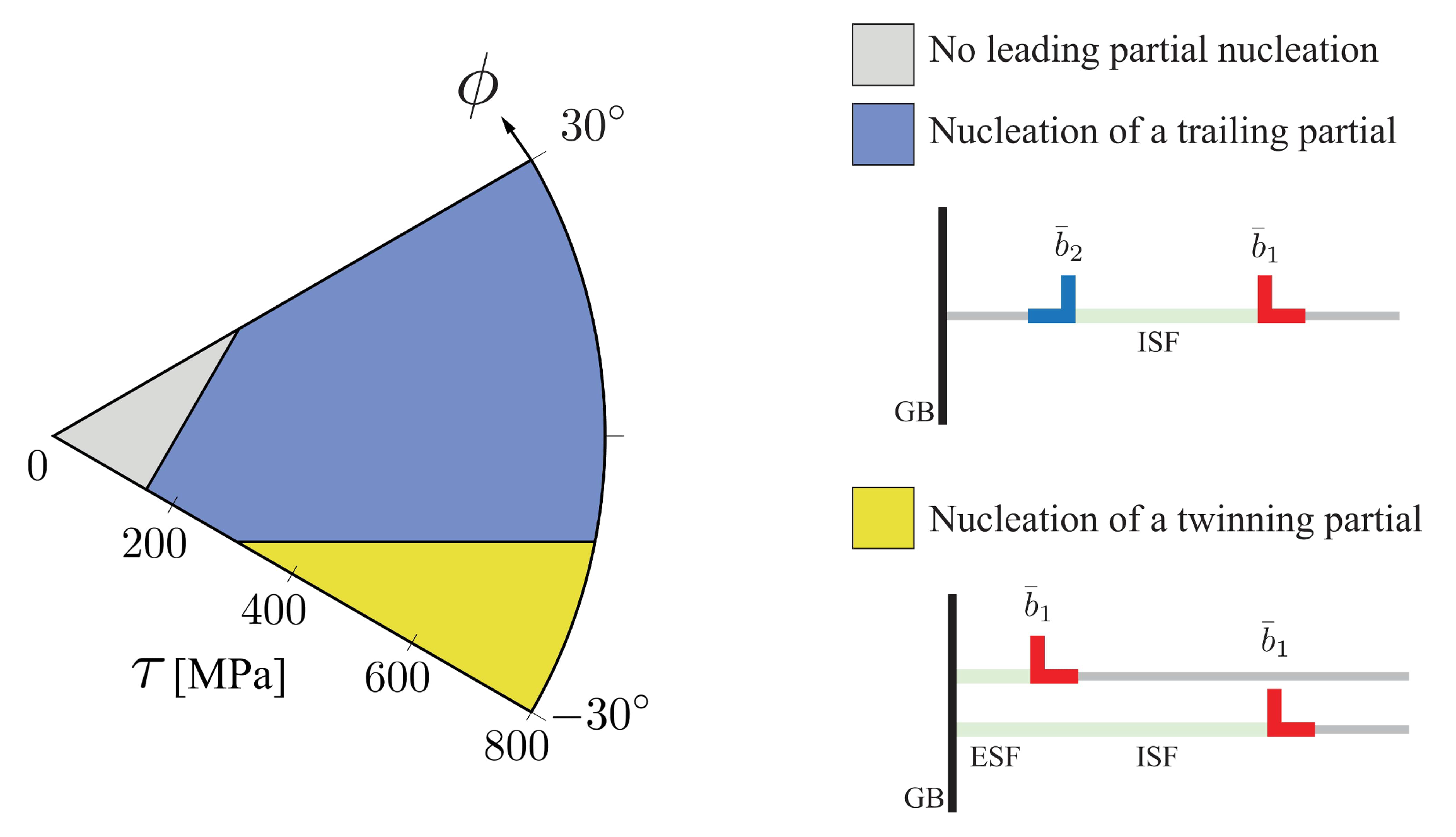
Figure 8.
Orientation dependence of McCabe’s criterion [38] for the nucleation from a grain boundary of a trailing partial bounding an intrinsic stacking fault or a twinning partial on an adjacent plane giving rise to an extrinsic stacking fault. Calculated for an Fe-22 wt.% Mn-0.6 wt.% C TWIP steel ( mJ m, nm) [25]. As this model is based on the competition between two different types of partials, only the reduced map within the domain of is required to show the orientation dependence.


Table 1.
Conversion formulae between variables used in different descriptions of the stress state of a dislocation.
Table 1.
Conversion formulae between variables used in different descriptions of the stress state of a dislocation.
| ( , ) | (m , ) | (, ) | |
| ( , ) | - | ||
| (m , ) | - | ||
| ( , ) | - | ||
© 2020 by the authors. Licensee MDPI, Basel, Switzerland. This article is an open access article distributed under the terms and conditions of the Creative Commons Attribution (CC BY) license (http://creativecommons.org/licenses/by/4.0/).
Share and Cite
MDPI and ACS Style
León-Cázares, F.D.; Rae, C.M.F. A Stress Orientation Analysis Framework for Dislocation Glide in Face-Centred Cubic Metals. Crystals 2020, 10, 445. https://0-doi-org.brum.beds.ac.uk/10.3390/cryst10060445
AMA Style
León-Cázares FD, Rae CMF. A Stress Orientation Analysis Framework for Dislocation Glide in Face-Centred Cubic Metals. Crystals. 2020; 10(6):445. https://0-doi-org.brum.beds.ac.uk/10.3390/cryst10060445
Chicago/Turabian StyleLeón-Cázares, Fernando Daniel, and Catherine Mary Fiona Rae. 2020. "A Stress Orientation Analysis Framework for Dislocation Glide in Face-Centred Cubic Metals" Crystals 10, no. 6: 445. https://0-doi-org.brum.beds.ac.uk/10.3390/cryst10060445
Note that from the first issue of 2016, this journal uses article numbers instead of page numbers. See further details here.