Article

Broadband Plasmonic Nanopolarizer Based on Different Surface Plasmon Resonance Modes in a Silver Nanorod

1
National Engineering Lab of Special Display Technology & Key Lab of Advanced Display Technology, Department of Opto-Electronic Information Science and Engineering, School of Instrument Science and Opto-Electronics Engineering, Hefei University of Technology, Hefei 230009, China
2
Aston Institute of Photonic Technologies, School of Engineering & Applied Science, Aston University, Birmingham B4 7ET, UK
3
State Key Laboratory of Environment-Friendly Energy Materials, Southwest University of Science and Technology, Mianyang 621000, China
4
Department of Optical Engineering, School of Electronic Science & Applied Physics, Hefei University of Technology, Hefei 230009, China
5
Key Laboratory of Materials Physics and Anhui Key Laboratory of Nanomaterials and Nanostructures, Institute of Solid State Physics, Chinese Academy of Sciences, Hefei 230031, China
*
Authors to whom correspondence should be addressed.
Submission received: 20 April 2020 / Revised: 28 May 2020 / Accepted: 29 May 2020 / Published: 31 May 2020
(This article belongs to the Special Issue Plasmonic Nanostructures)

Abstract

:
Conventional polarizers including sheet, wire-grid, prism, and Brewster-angle type polarizers are not easily integrated with photonic circuits. Polarizing elements on the nanoscale are indispensable for integrated all-optical nanophotonic devices. Here, we propose a plasmonic nanopolarizer based on a silver nanorod. The polarization characteristics result from the excitation of different resonance modes of localized surface plasmons (LSPs) at different wavelengths. Furthermore, the polarization characteristics in near field regions have been demonstrated by the electric field distribution of the nanorod based on finite-difference time-domain (FDTD) simulation, indicating a strong local resonant cavity with a standing wave mode for transverse electric (TE) polarization and weak electric fields distributed for transverse magnetic (TM) polarization. The nanopolarizer can efficiently work in the near field region, exhibiting a nanopolarization effect. In addition, very high extinction ratios and extremely low insertion losses can be achieved. Particularly, the nanopolarizer can work in a broadband from visible to near-infrared wavelengths, which can be tuned by changing the aspect ratio of the nanorod. The plasmonic nanopolarizer is a promising candidate for potential applications in the integration of nanophotonic devices and circuits.

1. Introduction

With the rapid development of information and communication techniques, data transmission rates with ultra-high speed greatly require increasing integration of photonic devices and circuits, and there are growing demands for the miniaturization and high performance of photonic devices. Polarization plays a key role in components such as switches, isolators, and modulators. However, conventional polarizing elements such as sheet polarizers by anisotropic absorption, wire-grid polarizer by anisotropic reflection, prism polarizer by refraction, and Brewster-angle polarizer by reflection near the Brewster angle [1], are not easily integrated with photonic circuits. To miniaturize the polarizing elements, micropolarizers have been developed by using in-line fibers [2,3,4,5], photonic crystals [6,7,8,9], nanowire-grids [10,11,12,13,14], plasmonic structures [15,16,17,18,19,20,21,22], and metasurfaces [23,24], etc, wherein the polarizers based on the plasmonic structures have been widely reported due to their high performance in recent years. For example, a band-selective polarizer by diffraction gratings consisting of periodically distributed gold nanowires has been presented, where the extinction ratio can be enhanced significantly by high-efficiency secondary diffraction [16]. Moreover, a broadband reflective and absorptive polarizer with large transmittance difference for orthogonally linearly polarized incident light in the visible range has been designed using multi-scaled Ag nano wire-slit arrays [20]. Recently, an ultrahigh extinction ratio and extremely short length resonant integrated optic transverse electric (TE) pass polarizer were proposed theoretically, which was based on the interaction between the short range surface plasmon polaritons (SPPs) and the mode guided by a dielectric waveguide [21]. Additionally, hybrid plasmonic waveguides based on TE pass polarizers have been designed by multilayer structures of a metal layer, dielectric spacer, and silicon-on-insulator, which exhibited high efficient polarization properties due to the mode coupling between SPPs and the dielectric waveguide [18,19,22]. It has been noted that the structures of the plasmonic polarizers are still complex and the component size is basically on the micrometer scale.
Since the micrometer-scale bulky components of photonic devices have limited the integration of these components on a much small scale further [25], nanophotonic components based on surface plasmons beyond the diffraction limit can make them ideal candidates for the integration of photonic devices on the nanometer scale [26,27,28,29,30]. In this case, the polarizing components on the nanoscale (i.e., nanopolarizers) are indispensable for their future applications.
It is noted that silver nanorods with a periodic arrangement have presented some significant properties and applications such as plasmonic waveguides with symmetric and antisymmetric modes [31], multiple electromagnetic responses to visible and near infrared (NIR ) wavelengths [32], and resonance cavities [30]. In this work, we theoretically investigated a broadband nanopolarizer based on a plasmonic nanorod. The nanopolarizer exhibited highly efficient polarization properties, which stems from the excitation of different resonance modes of localized surface plasmons (LSPs) in the nanorod at different wavelengths. The polarization behavior in near field regions has been explored based on finite-difference time-domain (FDTD) simulation; for the first time, a nanopolarization effect was demonstrated in the plasmonic nanorod, and particularly demonstrated that the nanopolarizer could efficiently work in the near field region close to the source edge (distance within 30 nm). Furthermore, the polarization properties were strongly dependent on the size parameters of the plasmonic nanorod and the near field range. Consequently, high extinction ratios and extremely low insertion losses at the visible to near-infrared wavelengths can be achieved by tuning the nanorod sizes.

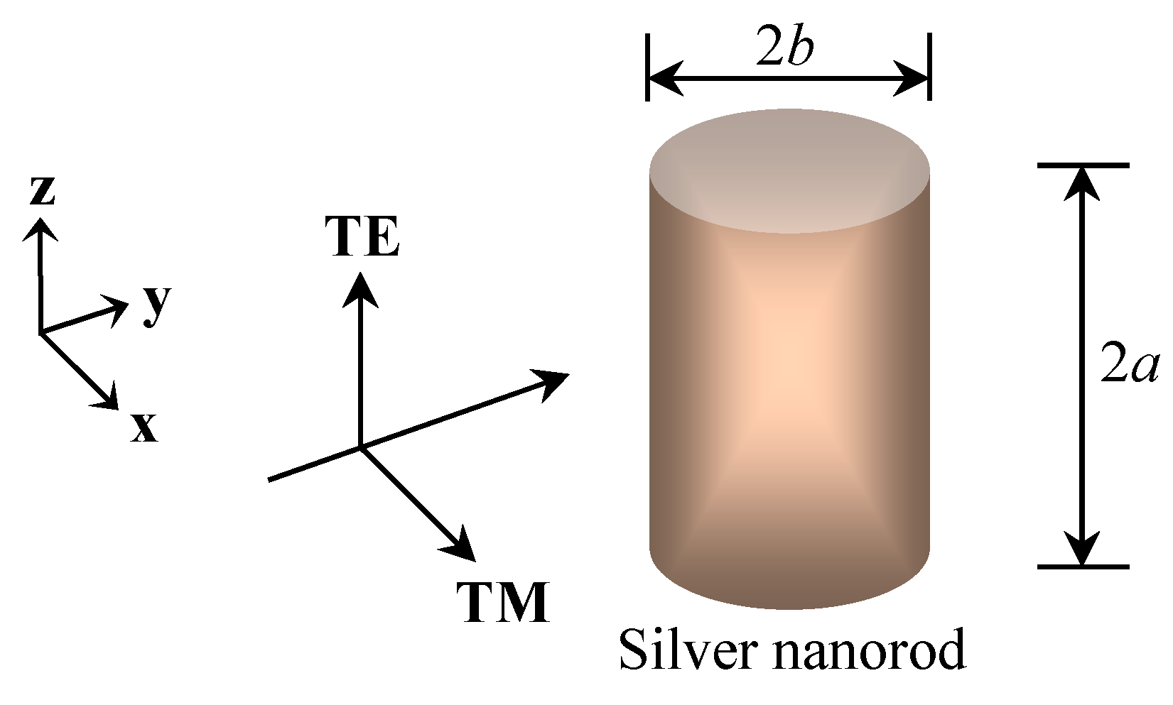
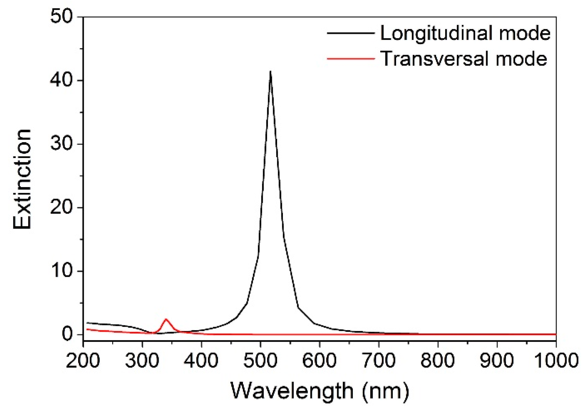
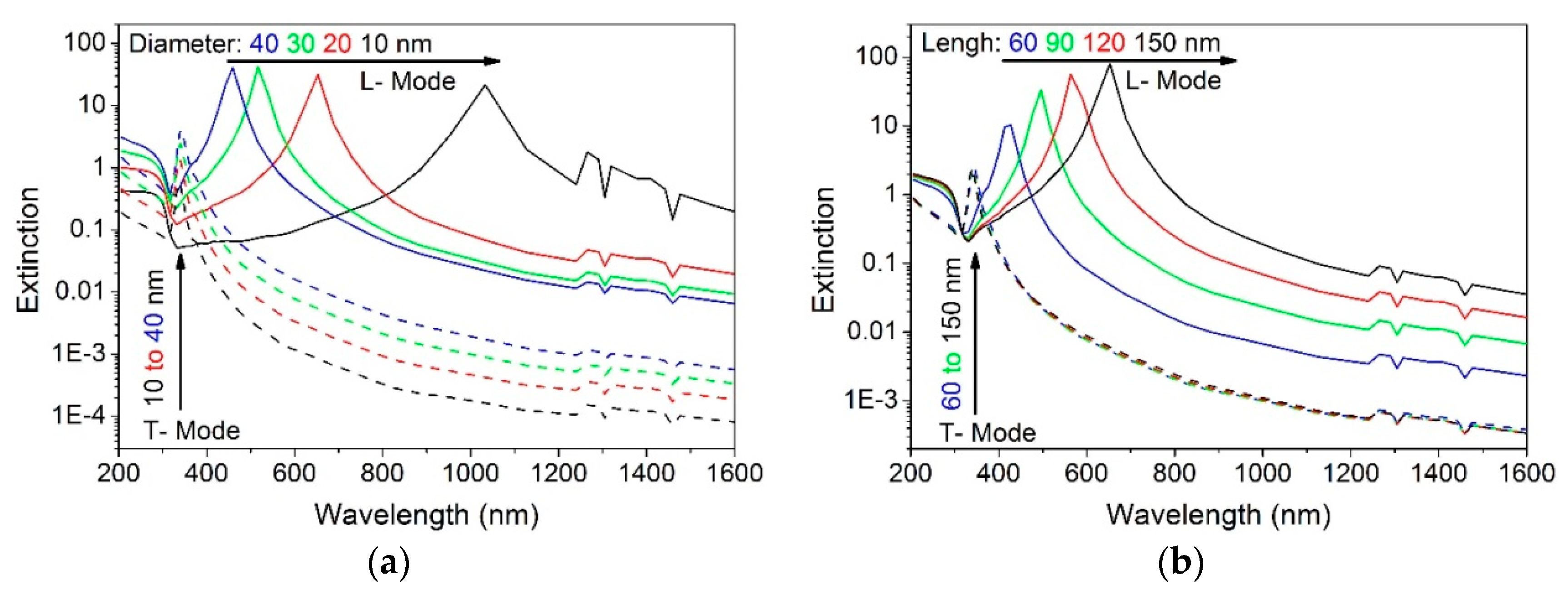
2. Extinction Properties of a Plasmonic Nanorod

Here we considered a single plasmonic nanorod (e.g., silver nanorod). When a light wave impinges on the surface of the silver nanorod at normal incidence along the y-direction (Figure 1), the electric polarization field is produced under the applied field, in this case [33]:
D = ε E = E + 4 π P
where D is the electric displacement; E is the macroscopic field inside the nanorod; P is the electric polarization per unit volume; and ε is the dielectric constant of silver. Moreover, the macroscopic field inside the nanorod is given by [34]
E = E 0 L j 4 π P
where E 0 is the electric field of the incident light, and the polarization directions of TE and TM waves are along the z- and x-directions, respectively. L j (j = z, x) is the Lorentz depolarization factor when E 0 is parallel and perpendicular to the long axis of the nanorod, respectively. It has been noted that the lower order mode (i.e., dipole) of LSPs is only excited when the nanostructure is very short (e.g., less than 280 nm) [35,36]. When considering the small nanorod compared to the wavelength, based on the dipole approximation, the electrostatic formula takes the form [34]
p = P V = α j E 0
where p is the dipole moment of the silver nanorod in the electric field; V denotes the volume of the silver nanorod; and α j is the polarizability tensor parallel (j = z) and perpendicular (j = x) to the long axis of the nanorod. In terms of Equations (1)–(3), the polarizability tensor takes the form
α j = V 4 π ε 1 1 + L j ( ε 1 )
Note that the polarizability tensor depends on the Lorentz depolarization factor, which is closely related to the polarization direction of incident light. When the polarization direction (or the applied electric field) is parallel to the long axis of the nanorod (along the z-direction, Figure 1), we have [37]
L z = a b 2 2 0 d s ( s + a 2 ) 3 2 ( s + b 2 )
where 2a and 2b correspond to the length and diameter of the nanorod, and for a > b, we have
L z = b 2 a 2 b 2 ( a 2 a 2 b 2 ln 1 + ε 1 ε 1 )
When the polarization direction is perpendicular to the long axis of the nanorod, we have
L x = ( 1 L z ) / 2
Furthermore, the extinction cross section C e x t , j (j = z, x) can be expressed as the sum of the absorption cross section C a b s , j and the scattering cross section C s c a , j
C e x t , j = C a b s , j + C s c a , j
Considering that the nanorod diameter is very small compared with those wavelengths, according to the Rayleigh approximation [34], we have
C a b s , j = 4 π k Im ( α j )
C s c a , j = 8 3 π k 4 | α j | 2
The wavenumber k can be expressed as k = 2π/λ, where λ is the wavelength of the incident wave in vacuum. For the nanorod, the extinction coefficient can be given by
α e x t , j = C e x t , j / ( 2 π a b 2 )
The transmittance has the conventional form of the exponential extinction law
I t , j = I 0 exp ( α e x t , j 2 b )
where I t , j and I 0 are the light intensity of the transmittance and incidence, respectively. The extinction E x t j (j = z, x) can be written as
E x t j = log I 0 I t , j = log e ( α e x t , j 2 b )
In terms of Equations (8)–(11), Equation (13) can be expressed as
E x t j = 4 log e a b ( k Im ( α j ) + 2 3 k 4 | α j | 2 )
The extinction spectra can be numerically simulated based on Equation (14), where the dielectric constants of silver are obtained from the compilations of Lynch and Hunter [38].
Figure 2 shows the calculated extinction spectra of the silver nanorod with a diameter of 30 nm and a length of 100 nm for the transverse electric (TE) and transverse magnetic (TM) polarized waves at normal incidence. When the polarization direction is parallel to the long axis of the nanorod (TE polarized wave), a very strong extinction peak appears at 517 nm due to the longitudinal resonance mode of LSPs. Nevertheless, when the polarization direction is perpendicular to the long axis (TM polarized wave), a weak extinction peak is observed due to the transversal mode that occurs at 340 nm. Additionally, the longitudinal resonance appears at a much longer wavelength, while the transversal resonance occurs at a shorter wavelength. It was demonstrated that the nanorod dramatically attenuates the light polarized parallel to the long axis at the wavelength of 517 nm, however, the nanorod strongly transmitted the light polarized perpendicular to the axis due to the week Rayleigh scattering at the 517 nm wavelength, which indicated an obvious polarization characteristic.

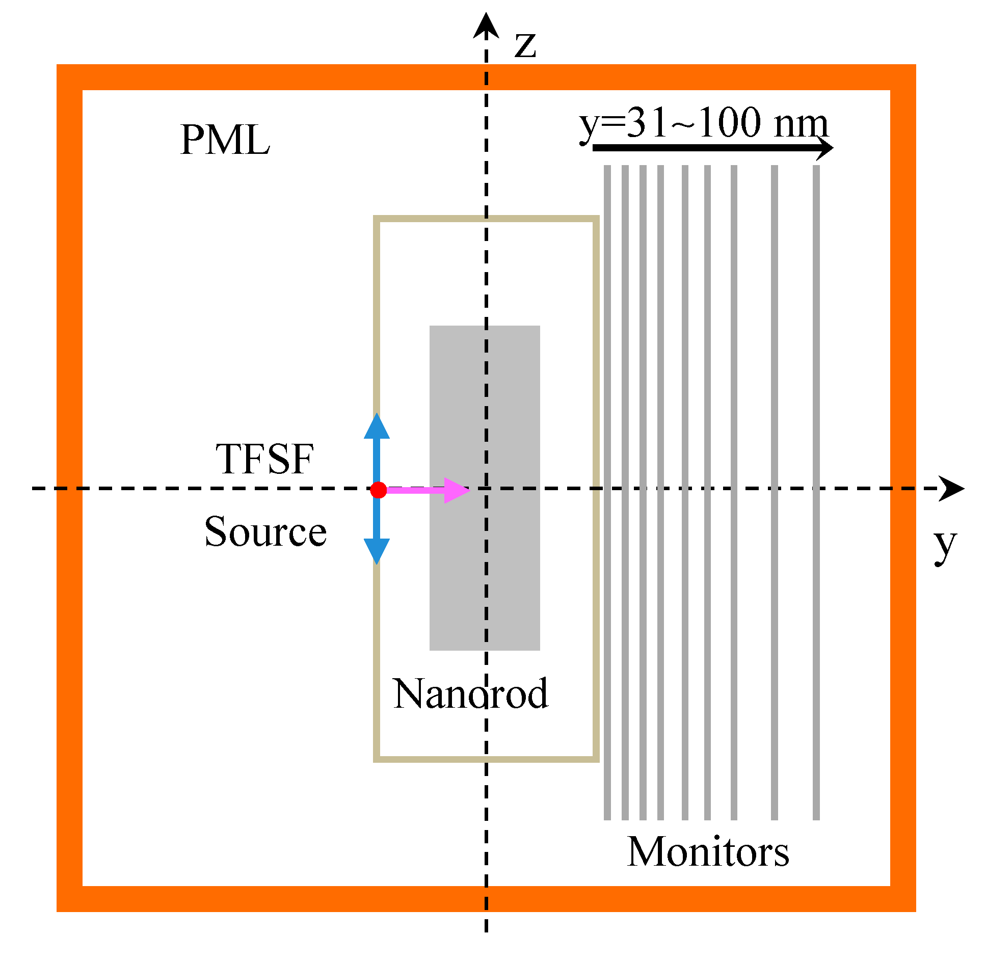
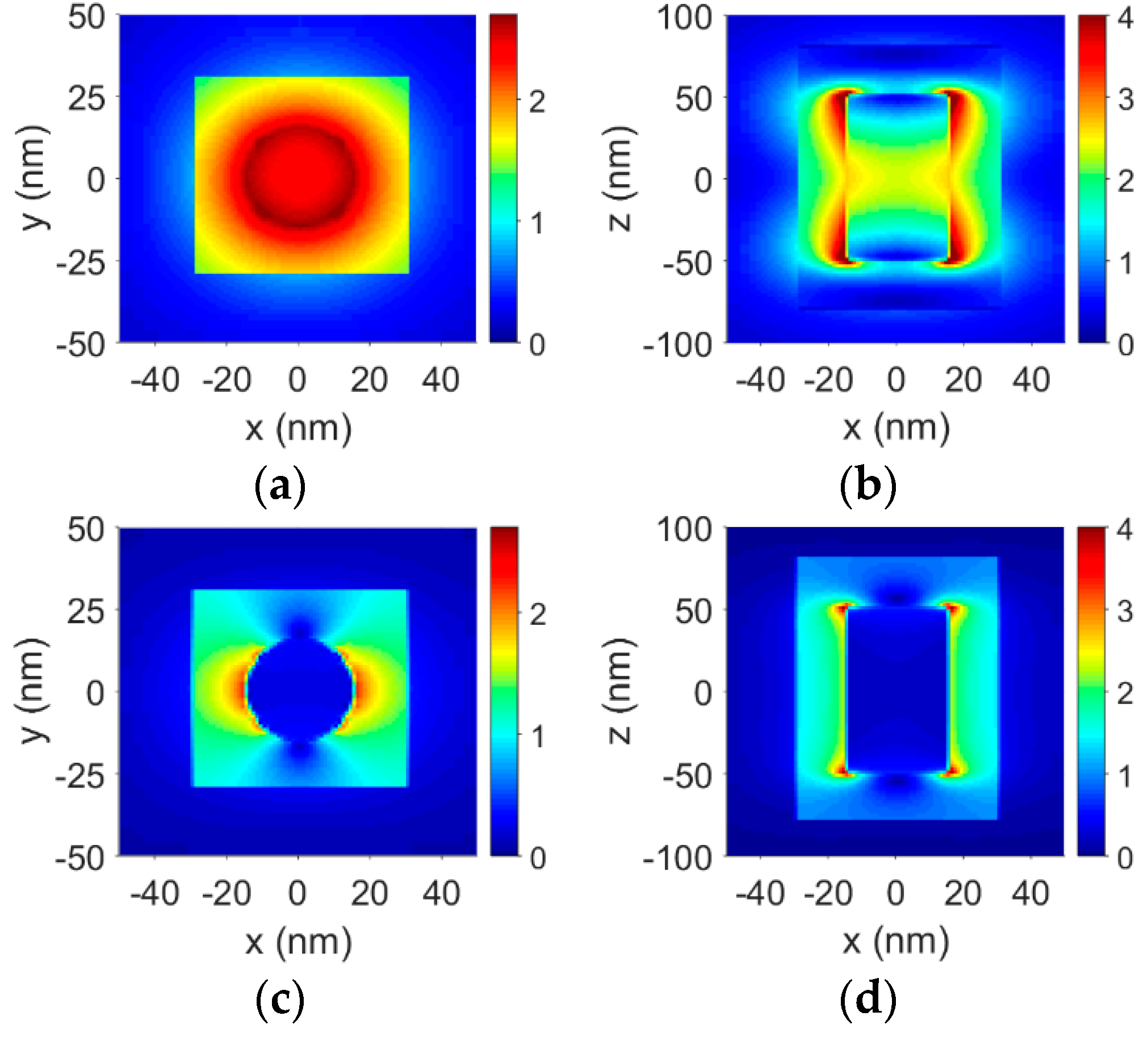
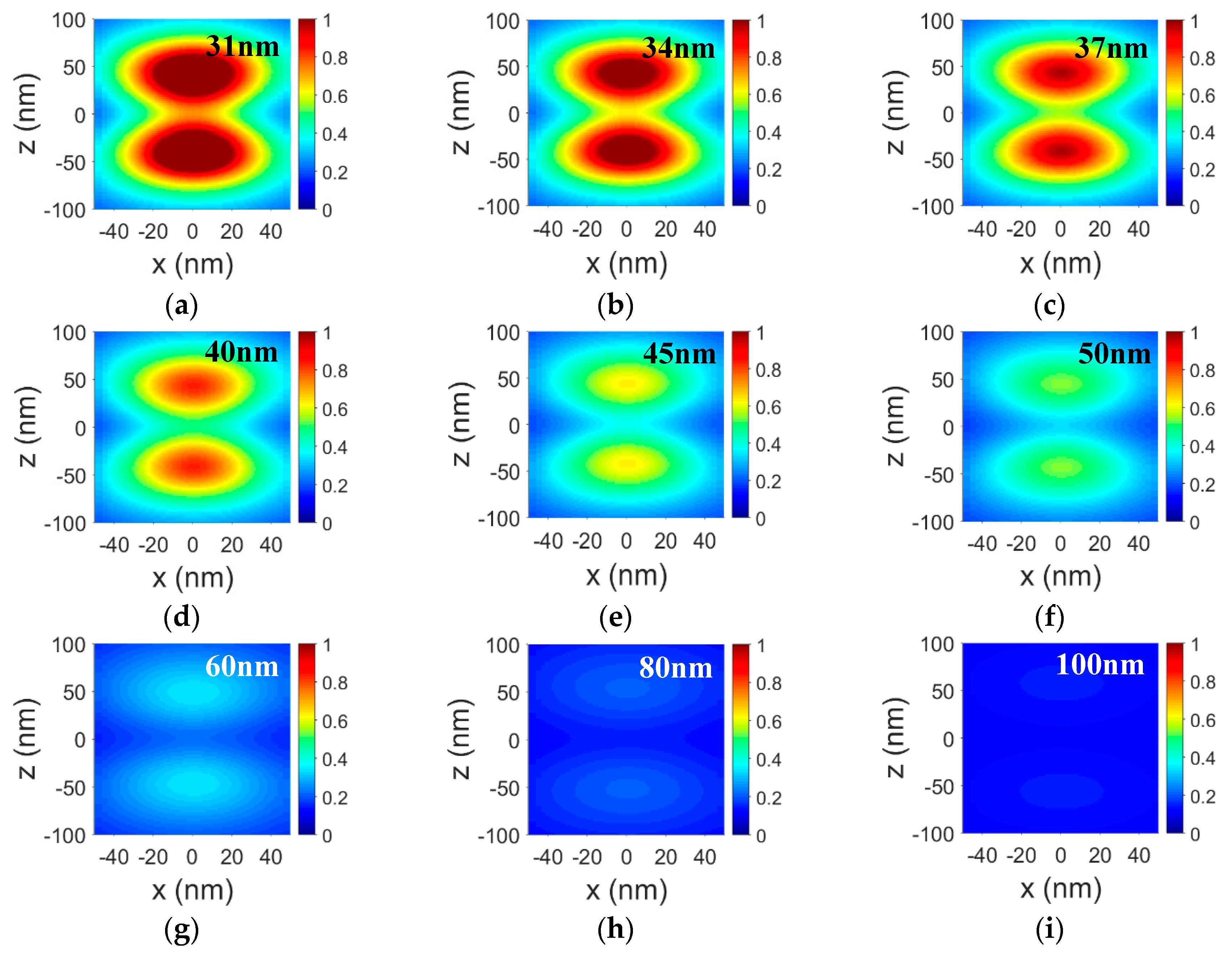
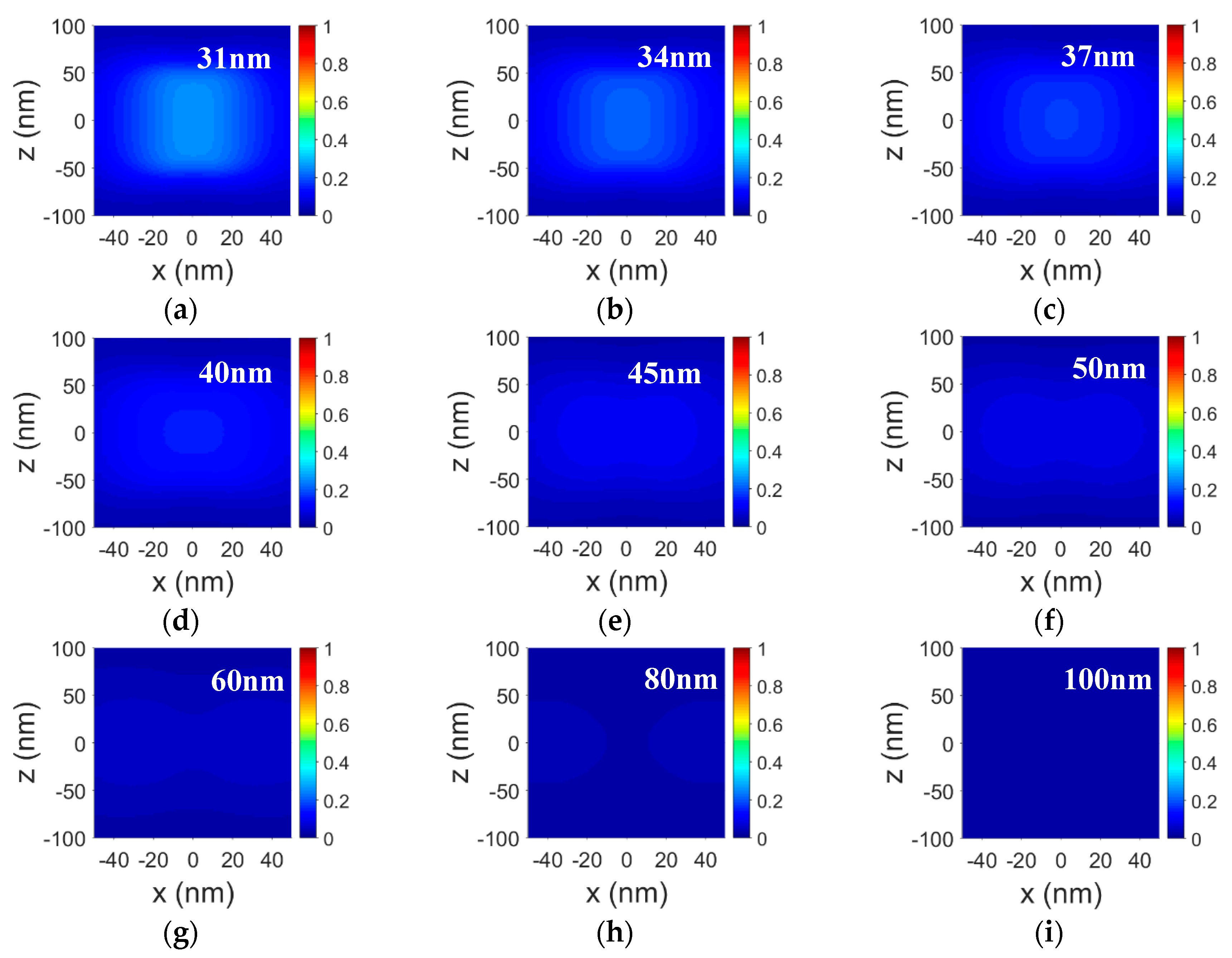
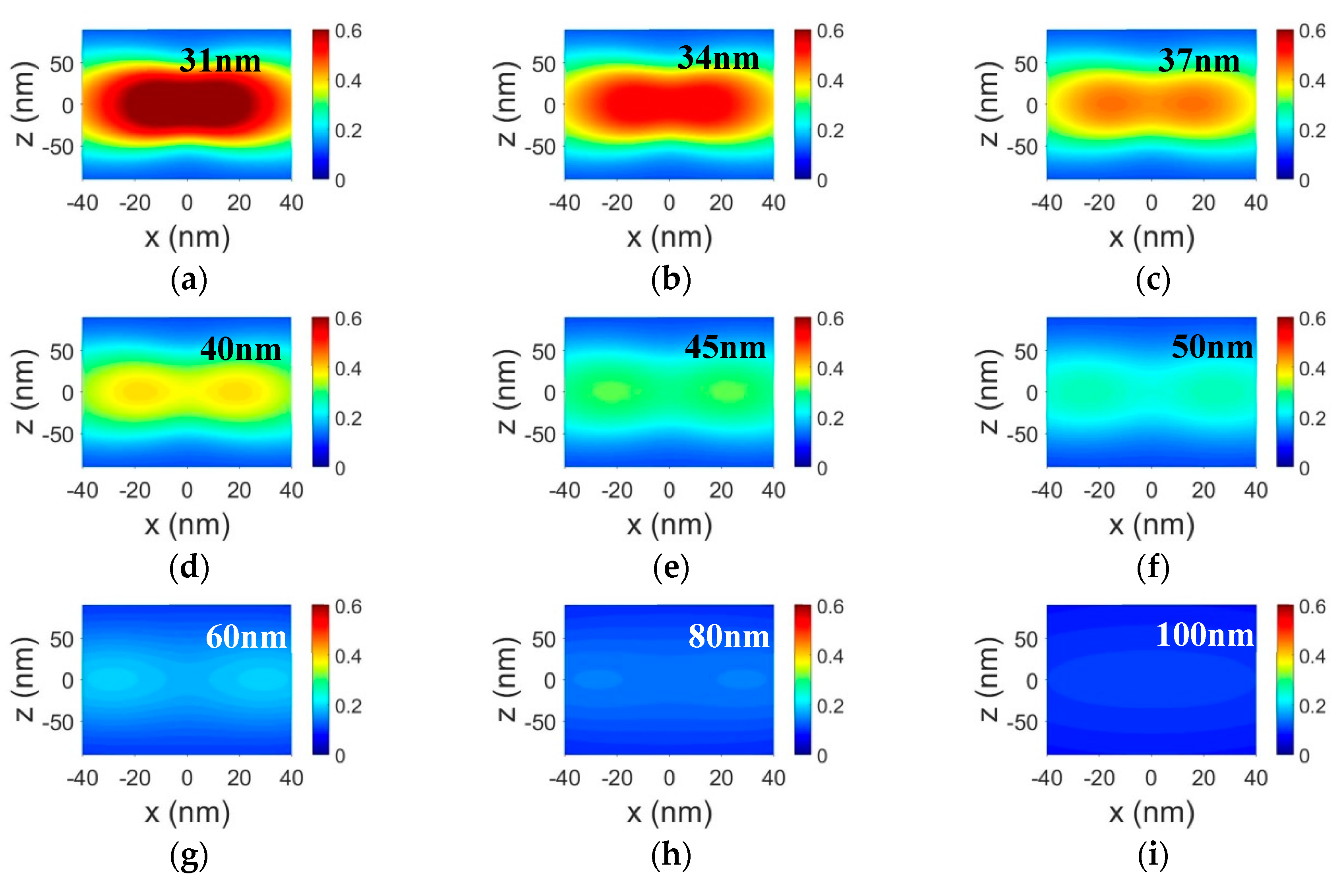
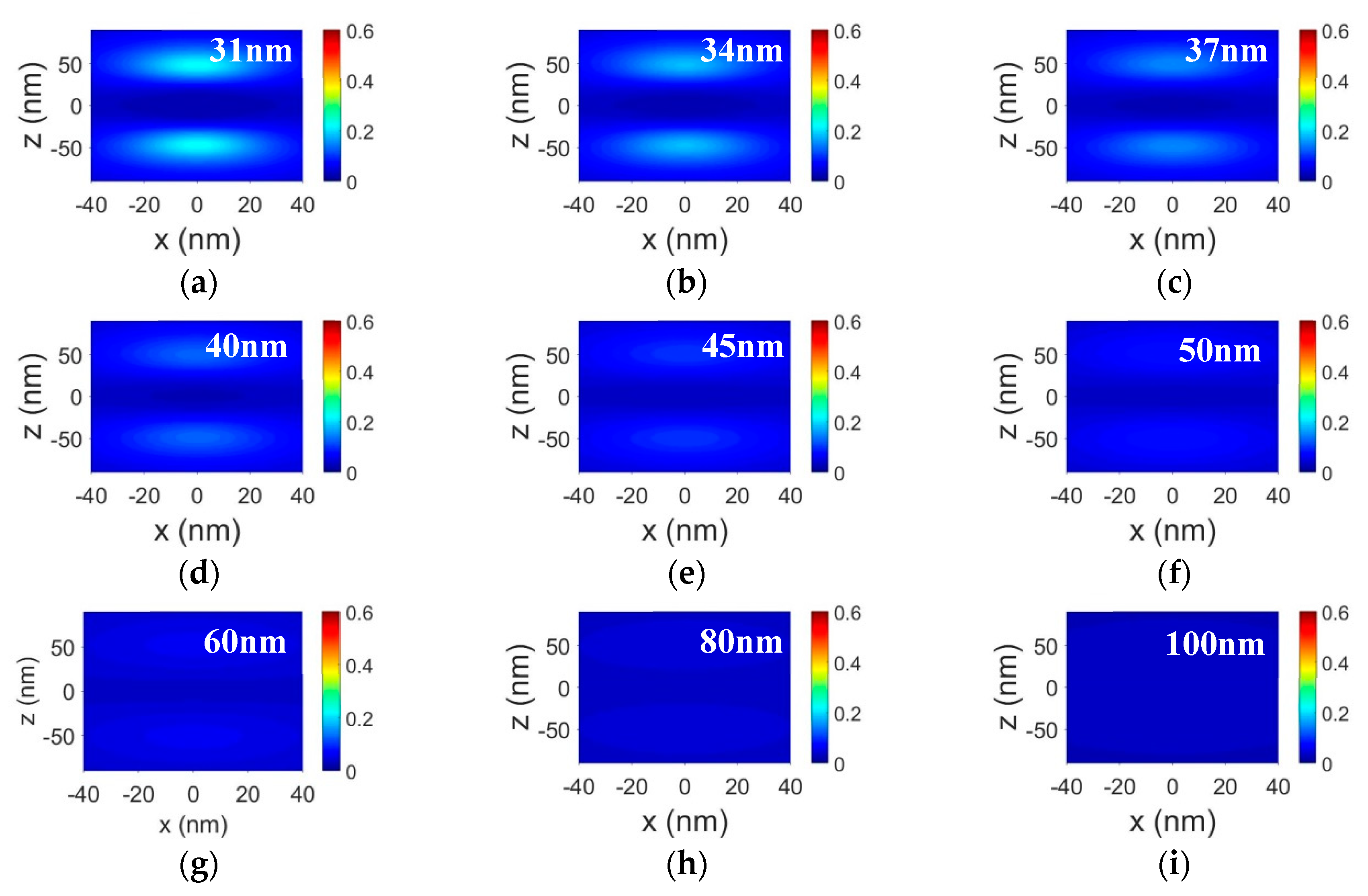
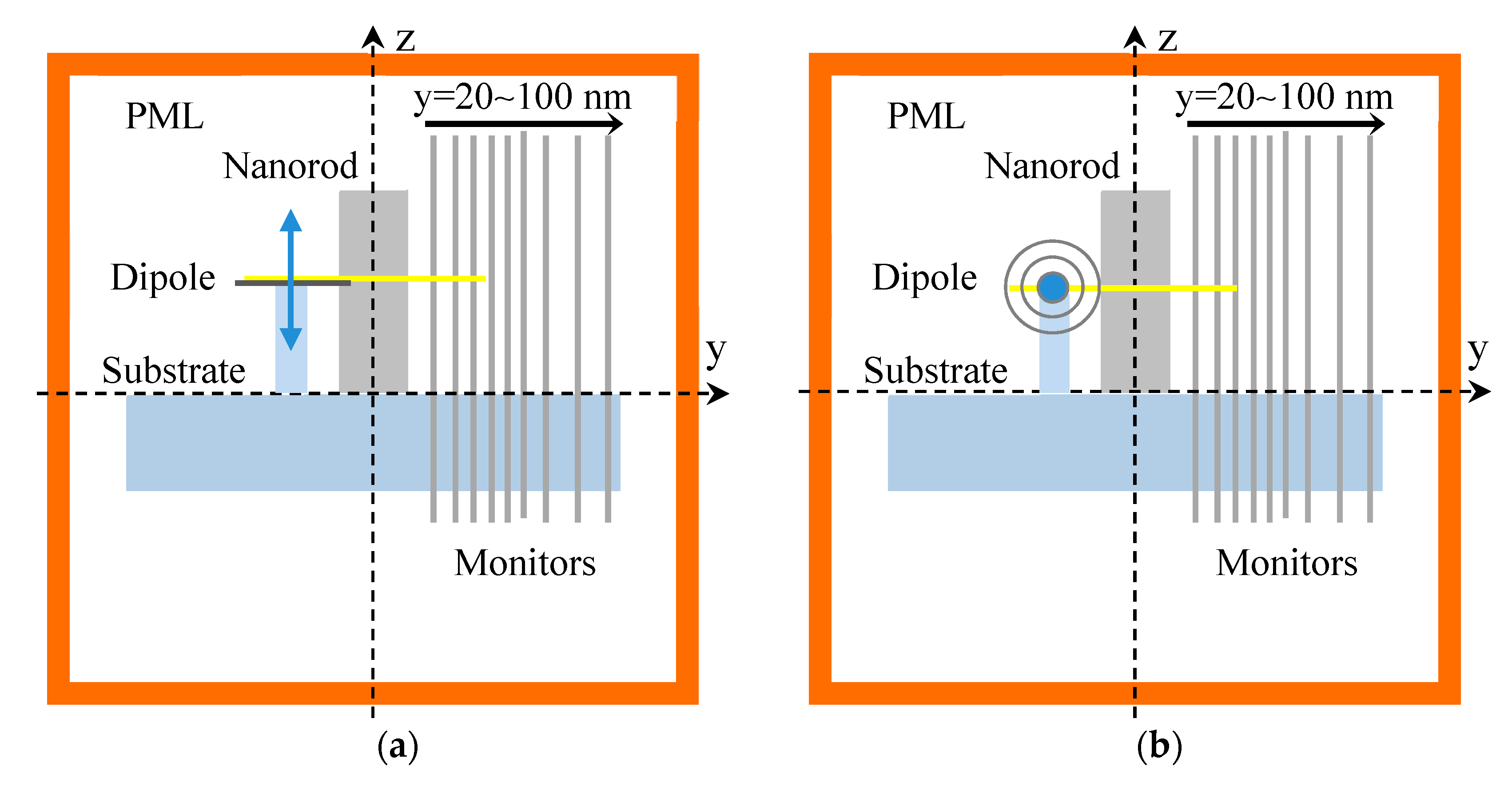
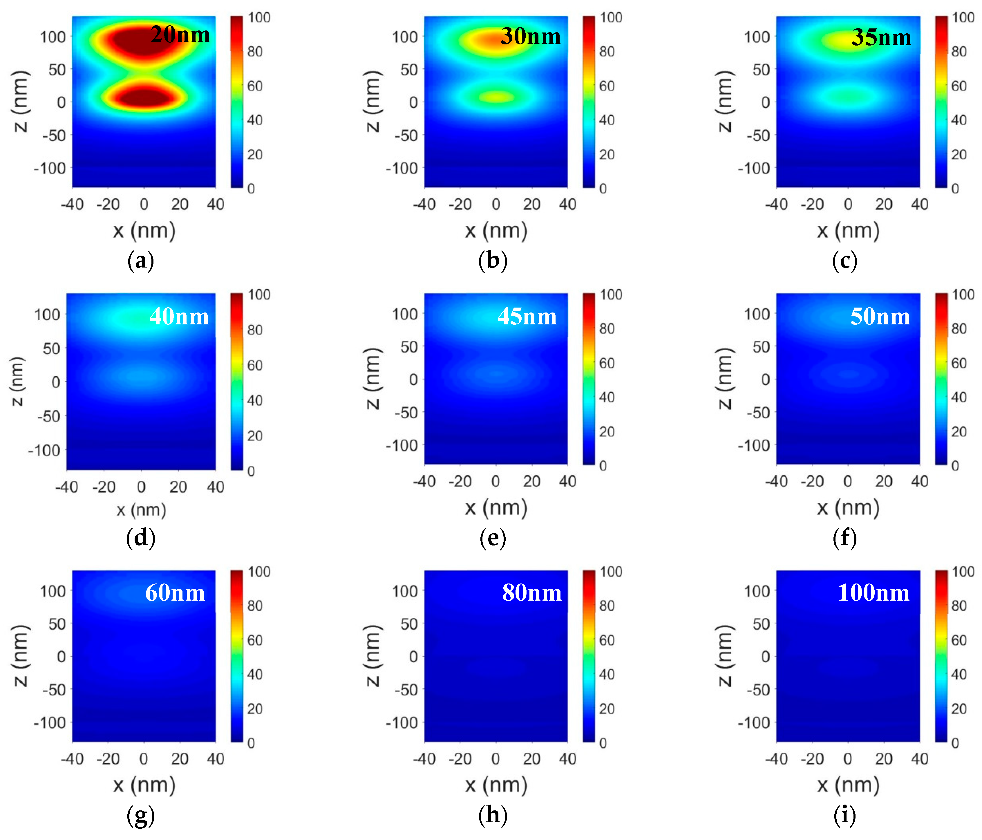
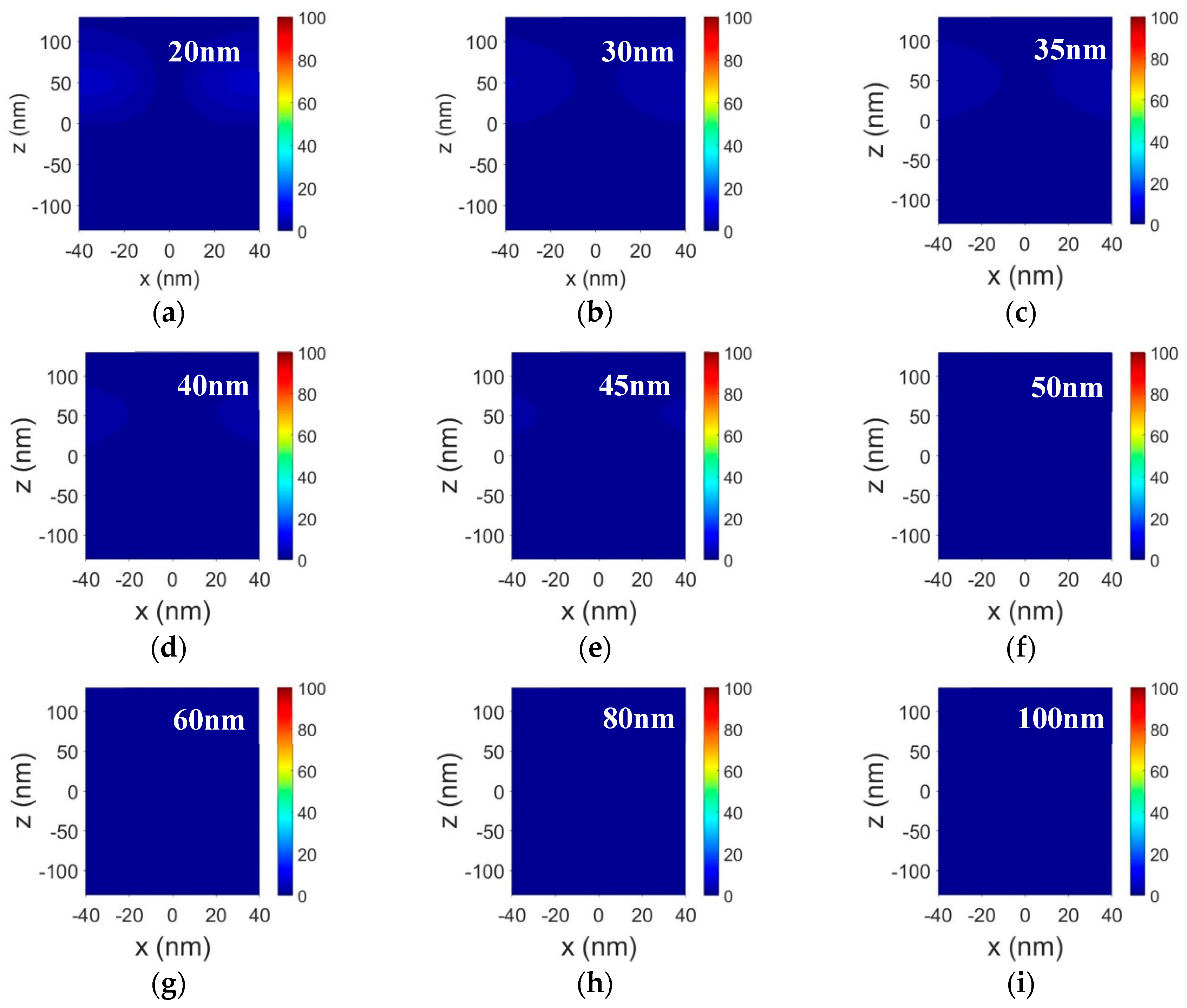
3. Simulation of Nanopolarization Characteristics in Near Field Region of the Plasmonic Nanorod

The polarization characteristics of the plasmonic nanorod with a 30 nm diameter and a 100 nm length was explored in near field regions by electric field distributions based on a 3D FDTD solutions with Lumerical package. Here, the refractive index of silver was selected in the material data from Ag (silver)-Palik (0–2 μm), the material fit had the tolerance of 10−5, and the max coefficient of 6. The total field scattered field (TFSF) method was used for investigating the near field distribution of the plasmonic nanorod with the PML boundary condition in the x-, y-, and z-directions. The mesh refinement was conformal variant 0 and the mesh override region covered the x-, y-, and z-mesh of 0.5 nm, 0.5 nm, and 1 nm, respectively. The injection direction of the TFSF source (with the wavelength range of 300 to 900 nm) with TE and TM polarizations was perpendicular to the long axis of the nanorod (along the y-direction) (Figure 3), where different types of monitors (such as the 2D z-normal monitor (x–y plane) and 2D y-normal monitor (x–z plane)) were selected to analyze the electric field distributions in different near field regions. The y-normal monitor that collected the electric field in x–z plane was put onto different positions with different y values of 31, 34, 37, 40, 45, 50, 60, 80, and 100 nm.
Figure 4 displays the electric field distributions of the plasmonic nanorod with the TE and TM polarizations of the incident light. It was found that the electric fields are obviously dependent on the polarization directions of the incident light (Figure 4a,c). For the TE polarization, the longitudinal resonance mode (L-mode) of the LSPs was excited at the wavelength of 517 nm, where it was noted that the electric field in the x–z plane is dominantly localized at the two ends of the nanorod (Figure 4b), and the electric field for the L-mode indicates a local resonant cavity with the standing wave mode, which results in the strong attenuation of the incident light with the polarization along the z-direction. In contrast, for the TM polarization, the transversal resonance mode (T-mode) of the LSPs was excited at a short wavelength (e.g., 340 nm). Since the resonance wavelength of the T-mode is very far from that of the L-mode, the electric field at the 517 nm wavelength displayed weak intensity and was mainly distributed at the rim of the nanorod along the x-direction (Figure 4c,d). As a result, the nanorod strongly transmits the incident light with the polarization along the x-direction. Thus, the plasmonic nanorod can be worked as a polarizing element at the resonance wavelength of the L-mode.
Furthermore, the polarization behavior in the near field area of the plasmonic nanorod can be demonstrated by the scattered fields in the x–z planes located at different near field regions. According to the TFSF technique, it has been noted that the scattered fields exceed the boundary of the TFSF source with a y-span range from −30 nm to 30 nm. Figure 5 illustrates the electric field distributions of the plasmonic nanorod in the x–z planes with different positions away from the source boundary (y = 30 nm) for the L-mode of LSPs, which is excited by the TE polarized wave (along the z-direction). Considering that the near field region in the x–z plane (y = 31 nm) is very close to the source edge (y = 30 nm), it was found that the L-mode exhibited a very strong resonant cavity mode at the two ends of the nanorod along the z-direction (Figure 5a). When the distance between the position of the y-normal monitor related to the nanorod center (e.g., y = 31, 34, 37, 40, 45, 50, and 60 nm) and the source edge (y = 30 nm) increased gradually from 1, 4, 7, 10, 20, to 30 nm (Figure 5a–f), the resonance intensity of the cavity mode reduced sharply; furthermore, the electric field became very weak when the distance was larger than 50 nm (y = 80 nm), and almost disappeared for the distance of 70 nm (y = 100 nm). As a result, for the TE polarization, the plasmonic nanorod exhibited the obvious extinction behavior only in the near field region localized in the range within the distance of 30 nm away from the source edge along the incident direction.
On the other hand, since the resonance wavelength of the T-mode is very far from that of the L-mode, for the incident light polarized perpendicular to the long axis of the nanorod (along the x-direction), the electric fields at the resonance wavelength of the L-mode were quite weak in the near field regions (Figure 6), nevertheless, when the distance between the y-normal monitor (e.g., y = 31, 34, 37, 40, 45, 50, and 60 nm) and the source edge (y = 30 nm) increased from 1, 4, 7, 10, 20, to 30 nm (Figure 6a–f), the electric fields polarized along the x-direction became weak and presented different geometry profiles with the distance. Additionally, their intensities were very weak with an increase in the distance (e.g., 50 and 70 nm). It is obvious that the plasmonic nanorod displayed the optical fields distributed in the near field range for the TM polarization. Based on the electric field distributions in the near field area for the TE and TM polarized waves, as described above, it was revealed that the plasmonic nanorod performed the polarization characteristics in the near field region with a distance within 30 nm from the source edge or 45 nm from the nanorod edge along the incident direction, that is, the plasmonic nanorod presented the polarization effect in the nanometer space, which is a nanopolarization effect, thus the plasmonic nanorod can serve as a nanopolarizer working in the specific near field range.
In contrast, for the TM polarized light, the T-mode of LSPs was excited at a short wavelength, corresponding to the extinction peak at 340 nm, while the extinction at 340 nm was very weak for the TE polarized light since the resonance wavelength of the L-mode was very far from that of the T-mode. Therefore, the plasmonic nanorod can be worked as a polarizer at the resonance wavelength of the T-mode. Figure 7 illustrates the electric field distributions of the plasmonic nanorod in the x–z planes with different positions away from the source boundary (y = 30 nm) for the T-mode of LSPs, which is excited by the TM polarized wave (along the x-direction). For the near field region in the x–z plane (y = 31 nm) very close to the source edge (y = 30 nm), it was found that the T-mode exhibited a strong resonance along the short axis of the nanorod (along the x-direction), and the electric field was distributed at the rim of the nanorod along the x-direction (Figure 7a). When the distance between the position of the y-normal monitor and the source edge (y = 30 nm) increased gradually from 1, 4, 7, 10, 15, 20, to 30nm (Figure 7a–g), the resonance intensity of the T-mode reduced sharply. Moreover, the electric field became very weak when the distance was larger than 50 nm (y = 80 and 100 nm). In this case, for the TM polarization, the nanorod working at the resonance wavelength of the T-mode exhibited extinction behavior only in the near field region localized in the range within the distance of 30 nm away from the source edge along the incident direction.
Additionally, for the incident light polarized along the long axis of the nanorod (z-direction), the electric field was dominantly localized at the two ends of the nanorod, however, the electric fields at the resonance wavelength of the T-mode were quite weak in the near field regions (Figure 8). When the distance between the y-normal monitor and the source edge (y = 30 nm) increased from 1, 4, 7, 10, to 20 nm (Figure 8a–f), the electric fields became weak and their intensities were very weak when the distance was larger than 30 nm. Considering the electric field distributions in the near field region for the TM and TE polarized waves, the plasmonic nanorod working at the wavelength of the T-mode performed the nanopolarization characteristics in the near field region.
It has been noted that the simulation model described above can be used to investigate the polarization characteristics in the near field region of the nanorod. However, if one considers the application of plasmonic polarizers in the integrated optics, a FDTD simulation model should be developed. As shown in Figure 9, the plasmonic nanorod needs to be supported by a substrate. Furthermore, it was noted that the injection plane of the TFSF source must be parallel to the substrate because the edges of the TFSF source must intersect the same refractive index profile along the injection direction. Therefore, the TFSF source is not available in the system of the nanorod on the substrate where the injection plane of the TFSF source is perpendicular to the substrate. Here, we selected electric dipole sources with different polarization directions (e.g., z and x) to excite the L-mode (Figure 9a) and the T-mode (Figure 9b) in the nanorod on the substrate, respectively.
Figure 10 displays the electric field distributions of the plasmonic nanorod on the SiO2 substrate in the x–z planes with different positions away from the nanorod boundary (y = 15 nm) for the L-mode, which is excited by the dipole source with the polarization direction along the long axis of the nanorod (along the z-direction). The L-mode has a very strong resonant cavity mode at the two ends of the nanorod along the z-direction at the y = 20 nm position (Figure 10a). It was noted that the electric field at the top end of the nanorod was stronger than that at the bottom end, which exhibited an asymmetric distribution due to the influence from the substrate. When the distance between the position of the y-normal monitor and the nanorod edge increased gradually from 5 to 85 nm (Figure 10a–f), the resonance intensity of the cavity mode decreased remarkably. Moreover, for the incident light polarized perpendicular to the long axis of the nanorod on the SiO2 substrate (along the x-direction), the electric fields at the resonance wavelength of the L-mode were quite weak in the near field regions (Figure 11), and the electric fields became weak with increasing distance between the y-normal monitor and the nanorod. Therefore, the plasmonic nanorod on the substrate also exhibited nanopolarization behavior in the near field regions.

4. Tuning the Polarization Properties of the Plasmonic Nanopolarizer in Visible to Near Infrared Spectral Range

The calculated extinction spectra of the plasmonic nanorod with different diameters and a constant length of 100 nm are shown in Figure 12a. It was found that the longitudinal resonance peak of LSPs displayed obvious blueshifts from 1033 to 653, 517 and 459 nm with increasing diameter from 10 to 20, 30, and 40 nm. Moreover, for a constant diameter (e.g., 30 nm), the longitudinal resonance peak remarkably redshifted from 428 to 496, 564 and 653 nm with increasing length of 60 to 90, 120, and 150 nm (Figure 12b). Note that when changing one quantity such as diameter (Figure 12a) or length (Figure 12b), the longitudinal resonance peak exhibited obvious shifts, which demonstrates that the resonance wavelength is not only dependent on diameter or length, but it is also closely related to the aspect ratio of the nanorod. For instance, the longitudinal resonance peak presented blueshifts from 1033 to 459 nm with decreasing aspect ratio from 10.0 to 5.0, 3.3 and 2.5 (Figure 12a). Additionally, the longitudinal resonance peak illustrated redshifts from 428 to 653 nm with increasing aspect ratio from 2 to 3, 4 and 5 (Figure 12b). This is because the free electrons in the metal move along the nanorod axis with weaker restoring forces [29], where the nanorod length is larger than the mean free paths of the electrons in the metal. In particular, longitudinal resonance appeared at the near infrared wavelengths by selecting larger aspect ratios (e.g., more than 5). Furthermore, for the constant aspect ratio, both the longitudinal and the transversal resonance peaks did not shift with a change in both the length and the diameter (Figure 13), which indicates that the resonance wavelength only depends on the aspect ratio. Therefore, the wavelength of the plasmonic nanopolarizer can be tuned at the visible to near infrared wavelengths (e.g., from 428 to 1033 nm) by adjusting the aspect ratio (e.g., from 2 to 10).
On the other hand, the extinction ratios 10 × log ( I 0 / I t , z ) of the nanorod were 214,9, 315.6, 414.5, and 403.4 dB at the wavelengths of 1033, 653, 517, and 459 nm with increasing diameter from 10 to 20, 30, and 40 nm for the constant length of 100 nm, respectively, where the insertion losses 10 × log ( I 0 / I t , x ) were 0.002, 0.02, 0.2 and 0.8 dB at the corresponding wavelengths (Figure 12a), which showed that the insertion loss sharply decreased with a reduction in the diameter at one fixed wavelength. It is indicated that both the extinction ratio and the insertion loss mainly increased with a reduction in wavelength for the constant length. Moreover, the extinction ratios were 103.3, 334.4, 566.0 and 809.3 dB at the wavelengths of 428, 496, 564, and 653 nm with an increase in length from 60 to 90, 120, and 150 nm for the fixed diameter of 30 nm, respectively, while the insertion losses were 0.8, 0.2, 0.1, and 0.06 dB at the corresponding wavelengths (Figure 12b), indicating that the insertion loss also decreased with increasing wavelength. Nevertheless, the nanorod length did not influence the insertion loss at a fixed diameter. Moreover, for a fixed wavelength, corresponding to the constant aspect ratio, both the extinction ratio and the insertion loss enhanced with an increase in the diameter and length (Figure 13). It is indicated that ultrahigh extinction ratio (e.g., 809.3 dB) and very low insertion loss (e.g., 0.06 dB) can be obtained by increasing the length of the nanorod (e.g., 150 nm, Figure 12b).

5. Conclusions

In summary, we proposed a plasmonic nanopolarizer based on a silver nanorod. The nanopolarizer exhibited highly efficient polarization properties, which stems from the remarkable differences between the resonance modes of LSPs at different wavelengths. The polarization performance can be confirmed by the electric field distribution of the plasmonic nanorod for different polarization directions by FDTD simulation, where the electric field distribution of the polarization properties of the plasmonic nanorod is remarkably dependent on the near field region, demonstrating a nanopolarization effect, in this case, the plasmonic nanopolarizer could efficiently work in the near field range with a distance within 30 nm from the source edge or 60 nm from the nanorod center along the incident direction. The working wavelength of the nanopolarizer can be tuned at the visible to near infrared wavelengths by adjusting the aspect ratio. Very high extinction ratio and extremely low insertion loss can be achieved by increasing the nanorod length. The plasmonic nanopolarizer is a promising candidate for potential applications in integrated all-optical nanophotonic devices and circuits.

Author Contributions

J.Z. and L.Z. conceived the concept; J.Z. presented the calculations and simulation; L.H., Y.W., and W.Z. participated in the discussion; and J.Z. and Z.H. wrote and reviewed the paper. All authors have read and agreed to the published version of the manuscript.

Funding

This research was funded by the National Natural Science Foundation of China (Nos. 51771186 and 11874012); the Fundamental Research Funds for the Central Universities (Nos. PA2018GDQT0006 and JZ2019HGPA0099); the Seventh Framework Program of the European Union for Research through Marie Curie Actions-International Incoming Fellowships (Nos. 623473 and 913473); and the Project of State Key Laboratory of Environment-Friendly Energy Materials, Southwest University of Science and Technology (No. 19FKSY0111).

Acknowledgments

We thank G. T. Fei from Institute of Solid State Physics, Chinese Academy of Sciences, for discussion about the work.

Conflicts of Interest

The authors declare no conflicts of interest.

References

  1. Goldstein, D. Polarized Light; Marcel Dekker: New York, NY, USA, 2003; pp. 497–538. [Google Scholar]
  2. Zhou, K.M.; Simpson, G.; Chen, X.F.; Zhang, L.; Bennion, I. High extinction ratio in-fiber polarizers based on 45 degrees tilted fiber Bragg gratings. Opt. Lett. 2005, 30, 1285–1287. [Google Scholar] [CrossRef] [PubMed] [Green Version]
  3. Yan, Z.; Zhou, K.; Zhang, L. In-fiber linear polarizer based on UV-inscribed 45 degrees tilted grating in polarization maintaining fiber. Opt. Lett. 2012, 37, 3819–3821. [Google Scholar] [CrossRef] [PubMed] [Green Version]
  4. Bao, Q.L.; Zhang, H.; Wang, B.; Ni, Z.H.; Lim, C.; Wang, Y.; Tang, D.Y.; Loh, K.P. Broadband graphene polarizer. Nat. Photonics 2011, 5, 411–415. [Google Scholar] [CrossRef]
  5. Dong, C.H.; Zou, C.L.; Ren, X.F.; Guo, G.C.; Sun, F.W. In-line high efficient fiber polarizer based on surface plasmon. Appl. Phys. Lett. 2012, 100, 041104. [Google Scholar] [CrossRef]
  6. Lu, Z.H.; Tang, Y.F.; Shen, Y.F.; Liu, X.H.; Zi, J. Polarization beam splitting in two-dimensional photonic crystals based on negative refraction. Phys. Lett. A. 2015, 346, 243–247. [Google Scholar] [CrossRef]
  7. Tagashira, K.; Yoshida, H.; Kubo, H.; Fujii, A.; Ozaki, M. Radial and azimuthal polarizer using a one-dimensional photonic crystal with a patterned liquid crystal defect layer. Appl. Phys. Express 2010, 3, 062002. [Google Scholar] [CrossRef]
  8. Sahani, P.; Vijaya, R. Polarizing properties of a 2D photonic crystal slab for simultaneous in-plane and out-of-plane light incidence. J. Phys. D Appl. Phys. 2018, 51, 355101. [Google Scholar] [CrossRef]
  9. Odoeze, J.A.H.; Hameed, M.F.O.; Shalaby, H.M.H.; Obayya, S.S.A. Si-core photonic crystal fiber transverse-electric pass polarizer. J. Opt. Soc. Am. B 2018, 35, 980–986. [Google Scholar] [CrossRef]
  10. Zhang, J.X.; Zhang, L.D.; Ye, C.H.; Chang, M.; Yan, Y.G.; Lu, Q.F. Polarization properties of ordered copper nanowire microarrays embedded in anodic alumina membrane. Chem. Phys. Lett. 2004, 400, 158–162. [Google Scholar] [CrossRef]
  11. Wang, J.J.; Zhang, W.; Deng, X.G.; Deng, J.D.; Liu, F.; Sciortino, P.; Chen, L. High-performance nanowire-grid polarizers. Opt. Lett. 2005, 30, 195–197. [Google Scholar] [CrossRef]
  12. Chen, L.; Wang, J.J.; Walters, F.; Deng, X.G.; Buonanno, M.; Tai, S.; Liu, X.M. Large flexible nanowire grid visible polarizer made by nanoimprint lithography. Appl. Phys. Lett. 2007, 90, 063001. [Google Scholar] [CrossRef]
  13. Wu, C.-L.; Sung, C.-K.; Yao, P.-H.; Chen, C.-H. Sub-15 nm linewidth gratings using roll-to-roll nanoimprinting and plasma trimming to fabricate flexible wire-grid polarizers with low colour shift. Nanotechnology 2013, 24, 265301. [Google Scholar] [CrossRef] [PubMed]
  14. Yoon, J.W.; Lee, K.J.; Magnusson, R. Ultra-sparse dielectric nanowire grids as wideband reflectors and polarizers. Opt. Express 2013, 23, 28849–28856. [Google Scholar] [CrossRef] [PubMed]
  15. Zhang, X.; Liu, H.; Tian, J.; Song, Y.; Wang, L.; Song, J.; Zhang, G. Optical polarizers based on gold nanowires fabricated using colloidal gold nanoparticles. Nanotechnology 2008, 19, 285202. [Google Scholar] [CrossRef] [PubMed]
  16. Zhang, X.; Liu, H.; Tian, J.; Song, Y.; Wang, L. Band-selective optical polarizer based on gold-nanowire plasmonic diffraction gratings. Nano Lett. 2008, 8, 2653–2658. [Google Scholar] [CrossRef] [PubMed]
  17. Rosenzveig, T.; Hermannsson, P.G.; Leosson, K. Modelling of polarization-dependent loss in plasmonic nanowire waveguides. Plasmonics 2010, 5, 75–77. [Google Scholar] [CrossRef]
  18. Sun, X.; Alam, M.Z.; Wagner, S.J.; Aitchison, J.S.; Mojahedi, M. Experimental demonstration of a hybrid plasmonic transverse electric pass polarizer for a silicon-on-insulator platform. Opt. Lett. 2012, 37, 4814–4816. [Google Scholar] [CrossRef]
  19. Alam, M.Z.; Aitchison, J.S.; Mojahedi, M. Compact and silicon-on-insulator-compatible hybrid plasmonic TE-pass polarizer. Opt. Lett. 2012, 37, 55–57. [Google Scholar] [CrossRef] [Green Version]
  20. Han, C.R.; Tam, W.Y. Plasmonic ultra-broadband polarizers based on Ag nano wire-slit arrays. Appl. Phys. Lett. 2015, 106, 081102. [Google Scholar] [CrossRef] [Green Version]
  21. Sharma, V.K.; Madaan, D.; Kapoor, A. High extinction ratio and short length surface plasmon polariton polarizer. IEEE Photonic. Technol. Lett. 2016, 28, 1541–1544. [Google Scholar] [CrossRef]
  22. Sun, X.; Mojahedi, M.; Aitchison, J.S. Hybrid plasmonic waveguide-based ultra-low insertion loss transverse electric-pass polarizer. Opt. Lett. 2016, 41, 4020–4023. [Google Scholar] [CrossRef] [PubMed]
  23. Shang, X.-J.; Zhai, X.; Wang, L.-L.; He, M.-D.; Li, Q.; Luo, X.; Duan, H.-G. Asymmetric transmission and polarization conversion of linearly polarized waves with bilayer L-shaped metasurfaces. Appl. Phys. Express 2017, 10, 052602. [Google Scholar] [CrossRef]
  24. Shang, X.-J.; Zhai, X.; Yue, J.; Luo, X.; Liu, J.-P.; Zhu, X.-P.; Duan, H.-G.; Wang, L.-L. Broad-band and high-efficiency polarization converters around 1550 nm based on composite structures. Opt. Express 2017, 25, 14406–14413. [Google Scholar] [CrossRef] [PubMed]
  25. Ozbay, E. Plasmonics: Merging photonics and electronics at nanoscale dimensions. Science 2006, 311, 189–193. [Google Scholar] [CrossRef]
  26. Gramotnev, D.K.; Bozhevolnyi, S.I. Plasmonics beyond the diffraction limit. Nat. Photonics 2010, 4, 83–91. [Google Scholar] [CrossRef]
  27. Schuller, J.A.; Barnard, E.S.; Cai, W.S.; Jun, Y.C.; White, J.S.; Brongersma, M.L. Plasmonics for extreme light concentration and manipulation. Nat. Mater. 2010, 9, 193–204. [Google Scholar] [CrossRef]
  28. Berini, P.; De Leon, I. Surface plasmon-polariton amplifiers and lasers. Nat. Photonics 2012, 6, 16–24. [Google Scholar] [CrossRef]
  29. Zhang, J.X.; Zhang, L.D. Nanostructures for surface plasmons. Adv. Opt. Photon. 2012, 4, 157–321. [Google Scholar] [CrossRef]
  30. Ma, R.M.; Oulton, R.F.; Sorger, V.J.; Zhang, X. Plasmon lasers: Coherent light source at molecular scales. Laser Photonics Rev. 2013, 7, 1–21. [Google Scholar] [CrossRef] [Green Version]
  31. Saj, W.M. FDTD simulations of 2D plasmon waveguide on silver nanorods in hexagonal lattice. Opt. Express 2005, 13, 4818–4827. [Google Scholar] [CrossRef]
  32. Kim, M.; Mun, J.; Bae, D.; Jeon, G.; Go, M.C.; Rho, J.; Kim, J.K. Accordion-like plasmonic silver nanorod array exhibiting multiple electromagnetic responses. NPG Asia Mater. 2018, 10, 190–196. [Google Scholar] [CrossRef]
  33. Aspnes, D.E. Optical properties of thin films. Thin Solid Films 1982, 89, 249–262. [Google Scholar] [CrossRef]
  34. van de Hulst, H.C. Light Scattering by Small Particles; Dover: New York, NY, USA, 1981; pp. 63–84. [Google Scholar]
  35. Wang, J.; Zhang, C.; Zhang, J.; Song, H.; Wang, P.; Lu, Y.; Fei, G.; Xu, W.; Xu, W.; Zhang, L.; et al. Hybrid plasmonic cavity modes in arrays of gold nanotubes. Adv. Opt. Mater. 2017, 5, 1600731. [Google Scholar] [CrossRef] [Green Version]
  36. Song, H.; Zhang, J.; Fei, G.; Wang, J.; Jiang, K.; Wang, P.; Lu, Y.; Iorsh, I.; Xu, W.; Jia, J.; et al. Near-field coupling and resonant cavity modes in plasmonic nanorod metamaterials. Nanotechnology 2016, 27, 415708. [Google Scholar] [CrossRef] [Green Version]
  37. Bohren, C.F.; Huffman, D.R. Absorption and Scattering of Light by Small Particles; Wiley: New York, NY, USA, 1998; pp. 130–157. [Google Scholar]
  38. Lynch, D.W.; Hunter, W.R. Handbook of Optical Constants of Solids; Palik, E.D., Ed.; Academic Press: Cambridge, MA, USA, 1985; pp. 350–357. [Google Scholar]
Figure 1. Schematic illustration of a single silver nanorod when the incident light impinges on the surface of the nanorod at normal incidence along the y-direction, where the z-direction is parallel to the long axis of the nanorod with a length of 2a and diameter of 2b. TE and TM correspond to the transverse electric and transverse magnetic polarized waves, respectively.
Crystals 10 00447 g001
Figure 2. The calculated extinction spectra of a silver nanorod with a diameter of 30 nm and a length of 100 nm.
Crystals 10 00447 g002
Figure 3. Schematic illustration of the finite-difference time-domain (FDTD) simulation domain of the silver nanorod when the incident TFSF source impinges on the nanorod surface at normal incidence along the y-direction (marked by the pink arrow), TE and TM polarizations are correspondingly denoted by the blue arrow and the red dot in the y–z plane. Both x- and y-span ranges were −15 nm to 15 nm and the z-span range of the nanorod was −50 nm to 50 nm. The simulation geometry with a mesh accuracy of 7 corresponded to the values: x = y = z = 0 and the x-, y-, and z-spans were 1100 nm, 1100 nm, and 1200 nm, respectively. Both x- and y-span ranges of the TFSF source were −30 nm to 30 nm and the z-span range was –80 nm to 80 nm.
Crystals 10 00447 g003
Figure 4. The electric field distributions of the silver nanorod with a diameter of 30 nm and a length of 100 nm. (a) and (b) represent the electric field profiles of E(x, y) and E(x, z) at 517 nm for the TE polarization in terms of a 2D z-normal monitor (z = 0) and a 2D y-normal monitor (y = 0), respectively; (c) and (d) correspond to the electric field profiles of E(x, y) and E(x, z) at 517 nm for the TM polarization based on a 2D z-normal monitor (z = 0) and a 2D y-normal monitor (y = 0), respectively.
Crystals 10 00447 g004
Figure 5. The electric field distributions of the single silver nanorod with a diameter of 30 nm and a length of 100 nm for the TE polarization of the incident light (along the z-direction). (ai) The electric field profiles of E(x, z) at 517 nm in different near field regions when adding the 2D y-normal monitor in the positions of y = 31, 34, 37, 40, 45, 50, 60, 80, and 100 nm, respectively.
Crystals 10 00447 g005
Figure 6. The electric field distributions of the silver nanorod with a diameter of 30 nm and a length of 100 nm for the TM polarization (along the x-direction). (ai) The electric field profiles of E(x, z) at 517 nm in different near field regions when adding the 2D y-normal monitor in the positions of y = 31, 34, 37, 40, 45, 50, 60, 80, and 100 nm, respectively.
Crystals 10 00447 g006
Figure 7. The electric field distributions of the single silver nanorod with a diameter of 30 nm and a length of 100 nm for the TM polarization of the incident light (along the x-direction). (ai) The electric field profiles of E(x, z) at 340 nm in different near field regions when adding the 2D y-normal monitor in the positions of y = 31, 34, 37, 40, 45, 50, 60, 80, and 100 nm, respectively.
Crystals 10 00447 g007
Figure 8. The electric field distributions of the silver nanorod with a diameter of 30 nm and a length of 100 nm for the TE polarization (along z direction). (ai) The electric field profiles of E(x, z) at 340 nm in different near field regions when adding the 2D y-normal monitor in the positions of y = 31, 34, 37, 40, 45, 50, 60, 80, and 100 nm, respectively.
Crystals 10 00447 g008
Figure 9. Schematic illustration of the FDTD simulation domain of the plasmonic nanorod on a SiO2 substrate. The incident light waves were two broadband electric dipole sources with the different polarization directions along the z- (a) and x- (b), respectively. The boundary conditions were PML in the x-, y-, and z-directions. Both x and y span ranges were −15 nm to 15 nm and the z-span range of the nanorod was 0 nm to 100 nm, and the z-span range of the substrate was −100 nm to 0 nm. The simulation geometry had a mesh accuracy of 7. The different power monitors with the 2D y-normal type (x–z plane) were selected to analyze the electric field distributions in different near field regions, and the y-normal monitor that collects the electric field in x–z plane were put onto the different positions with different y-values of 20, 30, 35, 40, 45, 50, 60, 80, and 100 nm.
Crystals 10 00447 g009
Figure 10. The electric field E(x, z) distributions of the silver nanorod on the SiO2 substrate with a diameter of 30 nm and a length of 100 nm for the incident dipole source with the z-polarization direction. (ai) Correspond to the monitor positions of y = 20, 30, 35, 40, 45, 50, 60, 80, and 100 nm.
Crystals 10 00447 g010
Figure 11. The electric field E(x, z) distributions of the silver nanorod on the SiO2 substrate with a diameter of 30 nm and a length of 100 nm for the incident dipole source with the x-polarization direction. (ai) Correspond to the monitor positions of y = 20, 30, 35, 40, 45, 50, 60, 80, and 100 nm.
Crystals 10 00447 g011
Figure 12. The calculated extinction spectra of the plasmonic nanopolarizer. (a) The nanorod with a fixed length of 100 nm and different diameters (e.g., 10, 20, 30, and 40 nm); (b) The nanorod with a constant diameter of 30 nm and different lengths (e.g., 150, 120, 90, and 60 nm).
Crystals 10 00447 g012
Figure 13. The calculated extinction spectra of a single silver nanorod with a constant aspect ratio of 5, the length 2a = 150, 100, and 50 nm, correspondingly, the diameter 2b = 30, 20, and 10 nm.
Crystals 10 00447 g013

