Local Vibrational Mode Analysis of π–Hole Interactions between Aryl Donors and Small Molecule Acceptors


Abstract
:1. Introduction
2. Computational Methods
3. Results/Discussion
3.1. Discussion of Model Chemistry
3.2. Overall Findings and General Trends
3.3. Aryl Substituent Effects
3.4. Nature of the Aryl Rings
3.5. Secondary Bonding Interactions
3.6. Characterization of Normal Modes
3.6.1. Normal Modes Related to the –Hole Interaction
3.6.2. Normal Modes Not Related to the –Hole Interaction
4. Conclusions
Supplementary Materials
Author Contributions
Funding
Acknowledgments
Conflicts of Interest
Abbreviations
| BE | Binding Energy |
| BSSE | Basis Set Superposition Error |
| CCP | Cage Critical Point |
| CNM | Characterization of Normal Modes |
| CT | Charge Transfer |
| DFT | Density Functional Theory |
| DE | Dissociation Energy |
| ESP | Electrostatic Potential |
| exp | Experimental |
| HB | Hydrogen Bond |
| lp | Lone–Pair |
| LVM | Local Vibrational Mode |
| MP2 | Møller–Plesset Perturbation Theory of Second Order |
| NBO | Natural Bond Orbital |
| NCI | Noncovalent Interaction |
| SBI | Secondary Bonding Interaction |
References
- Murray, J.S.; Lane, P.; Clark, T.; Riley, K.E.; Politzer, P. σ–Holes, π–Holes and Electrostatically–Driven Interactions. J. Mol. Model. 2011, 18, 541–548. [Google Scholar] [CrossRef]
- Politzer, P.; Murray, J.S.; Clark, T. Halogen Bonding: An Electrostatically–Driven Highly Directional Noncovalent Interaction. Phys. Chem. Chem. Phys. 2010, 12, 7748. [Google Scholar] [CrossRef] [PubMed]
- Murray, J.S.; Politzer, P. The Electrostatic Potential: An Overview. WIREs Comput. Mol. Sci. 2011, 1, 153–163. [Google Scholar] [CrossRef]
- Politzer, P.; Murray, J.S.; Clark, T. Halogen Bonding and other σ–Hole Interactions: A Perspective. Phys. Chem. Chem. Phys. 2013, 15, 11178. [Google Scholar] [CrossRef]
- Wang, H.; Wang, W.; Jin, W.J. σ–Hole Bond vs π–Hole Bond: A Comparison Based on Halogen Bond. Chem. Rev. 2016, 116, 5072–5104. [Google Scholar] [CrossRef]
- Frontera, A.; Bauzá, A. Concurrent Aerogen Bonding and Lone Pair/Anion–π Interactions in the Stability of Organoxenon Derivatives: A Combined CSD and Ab Initio Study. Phys. Chem. Chem. Phys. 2017, 19, 30063–30068. [Google Scholar] [CrossRef] [PubMed]
- Mitra, M.; Manna, P.; Bauzá, A.; Ballester, P.; Seth, S.K.; Choudhury, S.R.; Frontera, A.; Mukhopadhyay, S. 3–Picoline Mediated Self–Assembly of M(II)-Malonate Complexes (M = Ni/Co/Mn/Mg/Zn/Cu) Assisted by Various Weak Forces Involving Lone Pair–π, π–π, and Anion···π–Hole Interactions. J. Phys. Chem. B 2014, 118, 14713–14726. [Google Scholar] [CrossRef]
- Ran, J.; Hobza, P. On the Nature of Bonding in Lone Pair···π–Electron Complexes: CCSD(T)/Complete Basis Set Limit Calculations. J. Chem. Theory Comput. 2009, 5, 1180–1185. [Google Scholar] [CrossRef]
- Foroutan-Nejad, C.; Badri, Z.; Marek, R. Multi–Center Covalency: Revisiting the Nature of Anion–π Interactions. Phys. Chem. Chem. Phys. 2015, 17, 30670–30679. [Google Scholar] [CrossRef]
- Mooibroek, T.J. Coordinated Nitrate Anions can be Directional π–Hole Donors in the Solid State: A CSD Study. CrystEngComm 2017, 19, 4485–4488. [Google Scholar] [CrossRef]
- Azofra, L.M.; Alkorta, I.; Scheiner, S. Noncovalent Interactions in Dimers and Trimers of SO3 and CO. Theor. Chem. Acc. 2014, 133, 1586. [Google Scholar] [CrossRef]
- Alkorta, I.; Elguero, J.; Frontera, A. Not Only Hydrogen Bonds: Other Noncovalent Interactions. Crystals 2020, 10, 180. [Google Scholar] [CrossRef] [Green Version]
- Engdahl, A.; Nelander, B. A Matrix Isolation Study of the Interaction between Water and the Aromatic π–Electron System. J. Phys. Chem. 1987, 91, 2253–2258. [Google Scholar] [CrossRef]
- Engdahl, A.; Nelander, B. A Matrix Isolation Study of the Benzene–Water Interaction. J. Phys. Chem. 1985, 89, 2860–2864. [Google Scholar] [CrossRef]
- Gotch, A.J.; Zwier, T.S. Multiphoton Ionization Studies of Clusters of Immiscible Liquids. I. C6H6−(H2O)n, n = 1, 2. J. Chem. Phys. 1992, 96, 3388–3401. [Google Scholar] [CrossRef] [Green Version]
- Suzuki, S.; Green, P.G.; Bumgarner, R.E.; Dasgupta, S.; Goddard, W.A.; Blake, G.A. Benzene Forms Hydrogen Bonds with Water. Science 1992, 257, 942–945. [Google Scholar] [CrossRef]
- Gallivan, J.P.; Dougherty, D.A. Can Lone Pairs Bind to a π System? The Water···Hexafluorobenzene Interaction. Org. Lett. 1999, 1, 103–106. [Google Scholar] [CrossRef]
- Danten, Y.; Tassaing, T.; Besnard, M. On the Nature of the Water–Hexafluorobenzene Interaction. J. Phys. Chem. A 1999, 103, 3530–3534. [Google Scholar] [CrossRef]
- Raimondi, M.; Calderoni, G.; Famulari, A.; Raimondi, L.; Cozzi, F. The Benzene/Water/Hexafluorobenzene Complex: A Computational Study. J. Phys. Chem. A 2003, 107, 772–774. [Google Scholar] [CrossRef]
- Egli, M.; Sarkhel, S. Lone Pair–Aromatic Interactions: To Stabilize or Not to Stabilize. Acc. Chem. Res. 2007, 40, 197–205. [Google Scholar] [CrossRef]
- Baiocco, P.; Colotti, G.; Franceschini, S.; Ilari, A. Molecular Basis of Antimony Treatment in Leishmaniasis†. J. Med. Chem. 2009, 52, 2603–2612. [Google Scholar] [CrossRef] [PubMed]
- Hoffmann, J.M.; Sadhoe, A.K.; Mooibroek, T.J. π–Hole Interactions with Various Nitro Compounds Relevant for Medicine: DFT Calculations and Surveys of the Cambridge Structural Database (CSD) and the Protein Data Bank (PDB). Synthesis 2019, 52, 521–528. [Google Scholar] [CrossRef]
- Egli, M.; Gessner, R.V. Stereoelectronic effects of deoxyribose O4’ on DNA conformation. Proc. Natl. Acad. Sci. USA 1995, 92, 180–184. [Google Scholar] [CrossRef] [Green Version]
- Sarkhel, S.; Rich, A.; Egli, M. Water–Nucleobase “Stacking”: H–π and Lone Pair–π Interactions in the Atomic Resolution Crystal Structure of an RNA Pseudoknot. J. Am. Chem. Soc. 2003, 125, 8998–8999. [Google Scholar] [CrossRef]
- Belmont-Sánchez, J.C.; Ruiz-González, N.; Frontera, A.; Matilla-Hernández, A.; Castiñeiras, A.; Niclós-Gutiérrez, J. Anion–Cation Recognition Pattern, Thermal Stability and DFT–Calculations in the Crystal Structure of H2dap[Cd(HEDTA)(H2O)] Salt (H2dap = H2(N3,N7)–2,6–Diaminopurinium Cation). Crystals 2020, 10, 304. [Google Scholar] [CrossRef] [Green Version]
- Varadwaj, A.; Marques, H.M.; Varadwaj, P.R. Nature of Halogen–Centered Intermolecular Interactions in Crystal Growth and Design: Fluorine–Centered Interactions in Dimers in Crystalline Hexafluoropropylene as a Prototype. J. Comput. Chem. 2019, 40, 1836–1860. [Google Scholar] [CrossRef] [PubMed]
- Bauzá, A.; Sharko, A.V.; Senchyk, G.A.; Rusanov, E.B.; Frontera, A.; Domasevitch, K.V. π–Hole Interactions at Work: Crystal Engineering with Nitro–Derivatives. CrystEngComm 2017, 19, 1933–1937. [Google Scholar] [CrossRef]
- Bauzá, A.; Frontera, A.; Mooibroek, T.J. NO3− Anions can Act as Lewis Acid in the Solid State. Nat. Commun. 2017, 8, 14522. [Google Scholar] [CrossRef] [Green Version]
- Eliseeva, A.A.; Ivanov, D.M.; Novikov, A.S.; Kukushkin, V.Y. Recognition of the π–Hole Donor Ability of Iodopentafluorobenzene - a Conventional σ–Hole Donor for Crystal Engineering involving Halogen Bonding. CrystEngComm 2019, 21, 616–628. [Google Scholar] [CrossRef]
- Franconetti, A.; Frontera, A.; Mooibroek, T.J. Intramolecular π–Hole Interactions with Nitro Aromatics. CrystEngComm 2019, 21, 5410–5417. [Google Scholar] [CrossRef]
- Bauzá, A.; Frontera, A. σ/π–Hole Noble Gas Bonding Interactions: Insights from Theory and Experiment. Coord. Chem. Rev. 2020, 404, 213112. [Google Scholar] [CrossRef]
- Bauzá, A.; Frontera, A. Theoretical Study on the Dual Behavior of XeO3 and XeF4 toward Aromatic Rings: Lone Pair–π versus Aerogen–π Interactions. ChemPhysChem 2015, 16, 3625–3630. [Google Scholar] [CrossRef]
- Bauzá, A.; Frontera, A. π–Hole Aerogen Bonding Interactions. Phys. Chem. Chem. Phys. 2015, 17, 24748–24753. [Google Scholar] [CrossRef] [PubMed]
- Bauzá, A.; Mooibroek, T.J.; Frontera, A. The Bright Future of Unconventional σ/π–Hole Interactions. ChemPhysChem 2015, 16, 2496–2517. [Google Scholar] [CrossRef] [PubMed]
- Galmés, B.; Martínez, D.; Infante-Carrió, M.F.; Franconetti, A.; Frontera, A. Theoretical Ab Initio Study on Cooperativity Effects between Nitro π–Hole and Halogen Bonding Interactions. ChemPhysChem 2019, 20, 1135–1144. [Google Scholar] [CrossRef] [PubMed]
- Galmés, B.; Franconetti, A.; Frontera, A. Nitropyridine–1–Oxides as Excellent π–Hole Donors: Interplay between σ–Hole (Halogen, Hydrogen, Triel, and Coordination Bonds) and π–Hole Interactions. Int. J. Mol. Sci. 2019, 20, 3440. [Google Scholar] [CrossRef] [PubMed] [Green Version]
- Novikov, A.S.; Ivanov, D.M.; Bikbaeva, Z.M.; Bokach, N.A.; Kukushkin, V.Y. Noncovalent Interactions involving Iodofluorobenzenes: The Interplay of Halogen Bonding and Weak lp(O)···π–Holearene Interactions. Cryst. Growth Des. 2018, 18, 7641–7654. [Google Scholar] [CrossRef]
- Wheeler, S.E.; Houk, K.N. Are Anion/π Interactions Actually a Case of Simple Charge–Dipole Interactions? J. Phys. Chem. A 2010, 114, 8658–8664. [Google Scholar] [CrossRef] [Green Version]
- Garau, C.; Frontera, A.; Quiñonero, D.; Russo, N.; Deyà, P.M. RI–MP2 and MPWB1K Study of π–Anion–′ Complexes: MPWB1K Performance and Some Additivity Aspects. J. Chem. Theory Comput. 2011, 7, 3012–3018. [Google Scholar] [CrossRef] [PubMed]
- Politzer, P.; Murray, J.S. Electrostatics and Polarization in σ– and π–Hole Noncovalent Interactions: An Overview. ChemPhysChem 2020, 21, 579–588. [Google Scholar] [CrossRef] [PubMed]
- Politzer, P.; Murray, J.S.; Clark, T. Explicit Inclusion of Polarizing Electric Fields in σ– and π–Hole Interactions. J. Phys. Chem. A 2019, 123, 10123–10130. [Google Scholar] [CrossRef] [PubMed]
- Lang, T.; Li, X.; Meng, L.; Zheng, S.; Zeng, Y. The Cooperativity between the σ–Hole and π–Hole Interactions in the ClO···XONO2/XONO···NH3(X=Cl, Br, I) Complexes. Struct. Chem. 2014, 26, 213–221. [Google Scholar] [CrossRef]
- Zierkiewicz, W.; Michalczyk, M.; Wysokiński, R.; Scheiner, S. On the Ability of Pnicogen Atoms to Engage in both σ and π–Hole Complexes. HeteroDimers of ZF2C6H5 (Z=P, As, Sb, Bi) and NH3. J. Mol. Model. 2019, 25, 152. [Google Scholar] [CrossRef] [Green Version]
- Gao, L.; Zeng, Y.; Zhang, X.; Meng, L. Comparative Studies on Group III σ–Hole and π–Hole Interactions. J. Comput. Chem. 2016, 37, 1321–1327. [Google Scholar] [CrossRef]
- Guo, X.; Cao, L.; Li, Q.; Li, W.; Cheng, J. Competition between π–Hole Interaction and Hydrogen Bond in the Complexes of F2XO (X = C and Si) and HCN. J. Mol. Model. 2014, 20, 2493. [Google Scholar] [CrossRef]
- Katkova, S.A.; Mikherdov, A.S.; Kinzhalov, M.A.; Novikov, A.S.; Zolotarev, A.A.; Boyarskiy, V.P.; Kukushkin, V.Y. (Isocyano Group π–Hole)...[dZ2-MII] Interactions of (Isocyanide) [MII] Complexes, in which Positively Charged Metal Centers (d8–M=Pt, Pd) Act as Nucleophiles. Chem. Eur. 2019, 25, 8590–8598. [Google Scholar] [CrossRef] [PubMed]
- Liu, Z.F.; Chen, X.; Wu, W.X.; Zhang, G.Q.; Li, X.; Li, Z.Z.; Jin, W.J. 1,3,5–Trifluoro–2,4,6–triiodobenzene: A Neglected NIR Phosphor with Prolonged Lifetime by σ–Hole and π–Hole Capture. Spectrochim. Acta A 2020, 224, 117428. [Google Scholar] [CrossRef] [PubMed]
- Varadwaj, P.R.; Varadwaj, A.; Marques, H.M. Does Chlorine in CH3Cl Behave as a Genuine Halogen Bond Donor? Crystals 2020, 10, 146. [Google Scholar] [CrossRef] [Green Version]
- Rozhkov, A.V.; Krykova, M.A.; Ivanov, D.M.; Novikov, A.S.; Sinelshchikova, A.A.; Volostnykh, M.V.; Konovalov, M.A.; Grigoriev, M.S.; Gorbunova, Y.G.; Kukushkin, V.Y. Reverse Arene Sandwich Structures Based upon π–Hole···[MII](d8M=Pt, Pd) Interactions, where Positively Charged Metal Centers Play the Role of a Nucleophile. Angew. Chem. Int. Ed. 2019, 58, 4164–4168. [Google Scholar] [CrossRef]
- Prohens, R.; de Sande, D.; Font-Bardia, M.; Franconetti, A.; González, J.F.; Frontera, A. Gallic Acid Dimer As a Double π–Hole Donor: Evidence from X–ray, Theoretical Calculations, and Generalization from the Cambridge Structural Database. Cryst. Growth Des. 2019, 19, 3989–3997. [Google Scholar] [CrossRef]
- Shukla, R.; Claiser, N.; Souhassou, M.; Lecomte, C.; Balkrishna, S.J.; Kumar, S.; Chopra, D. Exploring the Simultaneous σ–Hole/π–Hole Bonding Characteristics of a Br···π Interaction in an Ebselen Derivative via Experimental and Theoretical Electron–Density Analysis. IUCrJ 2018, 5, 647–653. [Google Scholar] [CrossRef] [PubMed] [Green Version]
- Yang, F.L.; Yang, X.; Wu, R.Z.; Yan, C.X.; Yang, F.; Ye, W.; Zhang, L.W.; Zhou, P.P. Intermolecular Interactions between σ– and π–Holes of Bromopentafluorobenzene and Pyridine: Computational and Experimental Investigations. Phys. Chem. Chem. Phys. 2018, 20, 11386–11395. [Google Scholar] [CrossRef] [PubMed]
- Yang, F.L.; Lu, K.; Yang, X.; Yan, C.X.; Wang, R.; Ye, W.; Zhou, P.P.; Yang, Z. Computational Investigations of Intermolecular Interactions between Electron–Accepting Bromo– and Iodo–Pentafluorobenzene and Electron–Donating Furan and Thiophene. New J. Chem. 2018, 42, 20101–20112. [Google Scholar] [CrossRef]
- Zhang, J.; Hu, Q.; Li, Q.; Scheiner, S.; Liu, S. Comparison of σ–Hole and π–Hole Tetrel Bonds in Complexes of Borazine with TH3F and F2TO/H2TO (T= C, Si, Ge). Int. J. Quantum Chem. 2019, 119, e25910. [Google Scholar] [CrossRef]
- Zhang, Y.H.; Li, Y.L.; Yang, J.; Zhou, P.P.; Xie, K. Noncovalent Functionalization of Graphene via π–Hole···π and σ–Hole···π Interactions. Struct. Chem. 2019, 31, 97–101. [Google Scholar] [CrossRef]
- Mikherdov, A.S.; Kinzhalov, M.A.; Novikov, A.S.; Boyarskiy, V.P.; Boyarskaya, I.A.; Avdontceva, M.S.; Kukushkin, V.Y. Ligation–Enhanced π–Hole···π Interactions Involving Isocyanides: Effect of π–Hole···π Noncovalent Bonding on Conformational Stabilization of Acyclic Diaminocarbene Ligands. Inorg. Chem. 2018, 57, 6722–6733. [Google Scholar] [CrossRef]
- Kraka, E.; Cremer, D. Weaker Bonds with Shorter Bond Lengths. Rev. Proc. Quim. 2012, 6, 39–42. [Google Scholar] [CrossRef]
- Setiawan, D.; Kraka, E.; Cremer, D. Hidden Bond Anomalies: The Peculiar Case of the Fluorinated Amine Chalcogenides. J. Phys. Chem. A 2015, 119, 9541–9556. [Google Scholar] [CrossRef]
- Kraka, E.; Setiawan, D.; Cremer, D. Re–Evaluation of the Bond Length–Bond Strength Rule: The Stronger Bond Is not Always the Shorter Bond. J. Comp. Chem. 2015, 37, 130–142. [Google Scholar] [CrossRef]
- Cremer, D.; Kraka, E. From Molecular Vibrations to Bonding, Chemical Reactions, and Reaction Mechanism. Curr. Org. Chem. 2010, 14, 1524–1560. [Google Scholar] [CrossRef]
- Andrés, J.; Ayers, P.W.; Boto, R.A.; Carbó-Dorca, R.; Chermette, H.; Cioslowski, J.; Contreras-García, J.; Cooper, D.L.; Frenking, G.; Gatti, C.; et al. Nine questions on energy decomposition analysis. J. Comput. Chem. 2019, 40, 2248–2283. [Google Scholar] [CrossRef] [PubMed]
- Zhao, L.; von Hopffgarten, M.; Andrada, D.M.; Frenking, G. Energy Decomposition Analysis. WIREs Comput. Mol. Sci. 2017, 8, 1–37. [Google Scholar] [CrossRef]
- Stasyuk, O.A.; Sedlak, R.; Guerra, C.F.; Hobza, P. Comparison of the DFT-SAPT and canonical EDA Schemes for the energy decomposition of various types of noncovalent interactions. J. Chem. Theory Comput. 2018, 14, 3440–3450. [Google Scholar] [CrossRef]
- Levine, D.S.; Head-Gordon, M. Energy decomposition analysis of single bonds within Kohn-Sham density functional theory. Proc. Natl. Acad. Sci. USA 2017, 114, 12649–12656. [Google Scholar] [CrossRef] [Green Version]
- Lao, K.U.; Herbert, J.M. Energy Decomposition Analysis with a Stable Charge-Transfer Term for Interpreting Intermolecular Interactions. J. Chem. Theory Comput. 2016, 12, 2569–2582. [Google Scholar] [CrossRef] [PubMed]
- Kraka, E.; Larsson, J.A.; Cremer, D. Generalization of the Badger Rule Based on the Use of Adiabatic Vibrational Modes. In Computational Spectroscopy; Grunenberg, J., Ed.; Wiley: New York, NY, USA, 2010; pp. 105–149. [Google Scholar]
- Kalescky, R.; Zou, W.; Kraka, E.; Cremer, D. Local Vibrational Modes of the Water Dimer-Comparison of Theory and Experiment. Chem. Phys. Lett. 2012, 554, 243–247. [Google Scholar] [CrossRef]
- Zou, W.; Kalescky, R.; Kraka, E.; Cremer, D. Relating Normal Vibrational Modes to Local Vibrational Modes: Benzene and Naphthalene. J. Mol. Model. 2012, 19, 2865–2877. [Google Scholar] [CrossRef]
- Kalescky, R.; Kraka, E.; Cremer, D. Local Vibrational Modes of the Formic Acid Dimer–The Strength of the Double H–Bond. Mol. Phys. 2013, 111, 1497–1510. [Google Scholar] [CrossRef]
- Wilson, E.B.; Decius, J.C.; Cross, P.C. Molecular Vibrations; McGraw-Hill: New York, NY, USA, 1955. [Google Scholar]
- Woodward, L.A. Introduction to the Theory of Molecular Vibrations and Vibrational Spectroscopy; Oxford University Press: Oxford, UK, 1972. [Google Scholar]
- Herzberg, G. Molecular Spectra and Molecular Structure, 2nd ed.; Reitell Press: New York, NY, USA, 2008; Volume I. [Google Scholar]
- Herzberg, G. Molecular Spectra and Molecular Structure. Volume II: Infrared and Raman Spectra of Polyatomic Molecules; Krieger Publishing Co.: New York, NY, USA, 1991. [Google Scholar]
- Herzberg, G.; Huber, K.P. Molecular Spectra and Molecular Structure; IV. Constants of Diatomic Molecules; Van Nostrand, Reinhold: New York, NY, USA, 1979. [Google Scholar]
- Konkoli, Z.; Cremer, D. A New Way of Analyzing Vibrational Spectra. I. Derivation of Adiabatic Internal Modes. Int. J. Quant. Chem. 1998, 67, 1–9. [Google Scholar] [CrossRef]
- Konkoli, Z.; Larsson, J.A.; Cremer, D. A New Way of Analyzing Vibrational Spectra. II. Comparison of Internal Mode Frequencies. Int. J. Quant. Chem. 1998, 67, 11–27. [Google Scholar] [CrossRef]
- Konkoli, Z.; Cremer, D. A New Way of Analyzing Vibrational Spectra. III. Characterization of Normal Vibrational Modes in terms of Internal Vibrational Modes. Int. J. Quant. Chem. 1998, 67, 29–40. [Google Scholar] [CrossRef]
- Konkoli, Z.; Larsson, J.A.; Cremer, D. A New Way of Analyzing Vibrational Spectra. IV. Application and Testing of Adiabatic Modes within the Concept of the Characterization of Normal Modes. Int. J. Quant. Chem. 1998, 67, 41–55. [Google Scholar] [CrossRef]
- Cremer, D.; Larsson, J.A.; Kraka, E. New Developments in the Analysis of Vibrational Spectra on the Use of Adiabatic Internal Vibrational Modes. In Theoretical and Computational Chemistry; Parkanyi, C., Ed.; Elsevier: Amsterdam, The Netherlands, 1998; pp. 259–327. [Google Scholar]
- Kraka, E.; Zou, W.; Tao, Y. Decoding chemical information from vibrational spectroscopy data: Local vibrational mode theory. WIREs Comput. Mol. Sci. 2020, e1480. [Google Scholar] [CrossRef]
- Kraka, E.; Cremer, D. Dieter Cremer’s Contribution to the Field of Theoretical Chemistry. Int. J. Quantum Chem. 2019, 119, e25849. [Google Scholar] [CrossRef] [Green Version]
- Zou, W.; Kalescky, R.; Kraka, E.; Cremer, D. Relating Normal Vibrational Modes to Local Vibrational Modes with the Help of an Adiabatic Connection Scheme. J. Chem. Phys. 2012, 137, 084114. [Google Scholar] [CrossRef] [PubMed] [Green Version]
- Zou, W.; Cremer, D. C2 in a Box: Determining its Intrinsic Bond Strength for the X1Σ+g Ground State. Chem. Eur. J. 2016, 22, 4087–4097. [Google Scholar] [CrossRef]
- McKean, D.C. Individual CH bond strengths in simple organic compounds: Effects of conformation and substitution. Chem. Soc. Rev. 1978, 7, 399. [Google Scholar] [CrossRef]
- Kalescky, R.; Kraka, E.; Cremer, D. Identification of the Strongest Bonds in Chemistry. J. Phys. Chem. A 2013, 117, 8981–8995. [Google Scholar] [CrossRef]
- Kraka, E.; Cremer, D. Characterization of CF Bonds with Multiple–Bond Character: Bond Lengths, Stretching Force Constants, and Bond Dissociation Energies. ChemPhysChem 2009, 10, 686–698. [Google Scholar] [CrossRef]
- Setiawan, D.; Sethio, D.; Cremer, D.; Kraka, E. From Strong to Weak NF Bonds: On the Design of a New Class of Fluorinating Agents. Phys. Chem. Chem. Phys. 2018, 20, 23913–23927. [Google Scholar] [CrossRef]
- Sethio, D.; Lawson Daku, L.M.; Hagemann, H.; Kraka, E. Quantitative Assessment of B−B−B, B−Hb−B, and B−Ht Bonds: From BH3 to B12H122−. ChemPhysChem 2019, 20, 1967–1977. [Google Scholar] [CrossRef] [PubMed]
- Oliveira, V.; Kraka, E.; Cremer, D. The Intrinsic Strength of the Halogen Bond: Electrostatic and Covalent Contributions Described by Coupled Cluster Theory. Phys. Chem. Chem. Phys. 2016, 18, 33031–33046. [Google Scholar] [CrossRef] [PubMed]
- Oliveira, V.; Kraka, E.; Cremer, D. Quantitative Assessment of Halogen Bonding Utilizing Vibrational Spectroscopy. Inorg. Chem. 2016, 56, 488–502. [Google Scholar] [CrossRef] [PubMed]
- Oliveira, V.; Cremer, D. Transition from Metal–Ligand Bonding to Halogen Bonding Involving a Metal as Halogen Acceptor: A Study of Cu, Ag, Au, Pt, and Hg Complexes. Chem. Phys. Lett. 2017, 681, 56–63. [Google Scholar] [CrossRef]
- Yannacone, S.; Oliveira, V.; Verma, N.; Kraka, E. A Continuum from Halogen Bonds to Covalent Bonds: Where Do λ3 Iodanes Fit? Inorganics 2019, 7, 47. [Google Scholar] [CrossRef] [Green Version]
- Oliveira, V.; Cremer, D.; Kraka, E. The Many Facets of Chalcogen Bonding: Described by Vibrational Spectroscopy. J. Phys. Chem. A 2017, 121, 6845–6862. [Google Scholar] [CrossRef]
- Oliveira, V.; Kraka, E. Systematic Coupled Cluster Study of Noncovalent Interactions Involving Halogens, Chalcogens, and Pnicogens. J. Phys. Chem. A 2017, 121, 9544–9556. [Google Scholar] [CrossRef]
- Setiawan, D.; Kraka, E.; Cremer, D. Strength of the Pnicogen Bond in Complexes Involving Group VA Elements N, P, and As. J. Phys. Chem. A 2014, 119, 1642–1656. [Google Scholar] [CrossRef]
- Setiawan, D.; Kraka, E.; Cremer, D. Description of Pnicogen Bonding with the help of Vibrational Spectroscopy - The Missing Link Between Theory and Experiment. Chem. Phys. Lett. 2014, 614, 136–142. [Google Scholar] [CrossRef]
- Setiawan, D.; Cremer, D. Super–Pnicogen Bonding in the Radical Anion of the Fluorophosphine Dimer. Chem. Phys. Lett. 2016, 662, 182–187. [Google Scholar] [CrossRef] [Green Version]
- Sethio, D.; Oliveira, V.; Kraka, E. Quantitative Assessment of Tetrel Bonding Utilizing Vibrational Spectroscopy. Molecules 2018, 23, 2763. [Google Scholar] [CrossRef] [PubMed] [Green Version]
- Freindorf, M.; Kraka, E.; Cremer, D. A Comprehensive Analysis of Hydrogen Bond Interactions Based on Local Vibrational Modes. Int. J. Quant. Chem. 2012, 112, 3174–3187. [Google Scholar] [CrossRef]
- Tao, Y.; Zou, W.; Jia, J.; Li, W.; Cremer, D. Different Ways of Hydrogen Bonding in Water - Why Does Warm Water Freeze Faster than Cold Water? J. Chem. Theory Comput. 2016, 13, 55–76. [Google Scholar] [CrossRef] [PubMed]
- Tao, Y.; Zou, W.; Kraka, E. Strengthening of Hydrogen Bonding With the Push–Pull Effect. Chem. Phys. Lett. 2017, 685, 251–258. [Google Scholar] [CrossRef]
- Makoś, M.Z.; Freindorf, M.; Sethio, D.; Kraka, E. New Insights into Fe–H2 and Fe–H− Bonding of a [NiFe] Hydrogenase Mimic – A Local Vibrational Mode Study. Theor. Chem. Acc. 2019, 138, 76. [Google Scholar]
- Makoś, M.Z.; Zou, W.; Freindorf, M.; Kraka, E. Metal-Ring Interactions in Actinide Sandwich Compounds: A Combined Normalized Elimination of the Small Component and Local Vibrational Mode Study. Mol. Phys. 2020, in press. [Google Scholar]
- Zhang, X.; Dai, H.; Yan, H.; Zou, W.; Cremer, D. B–H π Interaction: A New Type of Nonclassical Hydrogen Bonding. J. Am. Chem. Soc. 2016, 138, 4334–4337. [Google Scholar] [CrossRef]
- Zou, W.; Zhang, X.; Dai, H.; Yan, H.; Cremer, D.; Kraka, E. Description of an Unusual Hydrogen Bond Between Carborane and a Phenyl Group. J. Organometal. Chem. 2018, 865, 114–127. [Google Scholar] [CrossRef]
- Burianova, V.K.; Bolotin, D.S.; Mikherdov, A.S.; Novikov, A.S.; Mokolokolo, P.P.; Roodt, A.; Boyarskiy, V.P.; Dar’in, D.; Krasavin, M.; Suslonov, V.V.; et al. Mechanism of Generation of Closo- Amidrazones. Intramol. Non- B−H···π(Ph) Interact. Determ. Stab. Config. Around Amidrazone C=N Bond. New J. Chem. 2018, 42, 8693–8703. [Google Scholar] [CrossRef]
- Alkorta, I.; Rozas, I.; Elguero, J. An Attractive Interaction between the π–Cloud of C6F6 and Electron-Donor Atoms. J. Org. Chem. 1997, 62, 4687–4691. [Google Scholar] [CrossRef]
- Alkorta, I.; Rozas, I.; Elguero, J. Interaction of Anions with Perfluoro Aromatic Compounds. J. Am. Chem. Soc. 2002, 124, 8593–8598. [Google Scholar] [CrossRef]
- Mascal, M.; Armstrong, A.; Bartberger, M.D. Anion-Aromatic Bonding: A Case for Anion Recognition by π–Acidic Rings. J. Am. Chem. Soc. 2002, 124, 6274–6276. [Google Scholar] [CrossRef] [PubMed]
- Quiñonero, D.; Garau, C.; Rotger, C.; Frontera, A.; Ballester, P.; Costa, A.; Deyà, P.M. Anion–π Interactions: Do They Exist? Angew. Chem. Int. Ed. 2002, 41, 3389–3392. [Google Scholar] [CrossRef]
- Chai, J.D.; Head-Gordon, M. Systematic Optimization of Long–Range Corrected Hybrid Density Functionals. J. Chem. Phys. 2008, 128, 084106. [Google Scholar] [CrossRef] [PubMed]
- Chai, J.D.; Head-Gordon, M. Long–Range Corrected Hybrid Density Functionals with Damped Atom–Atom Dispersion Corrections. Phys. Chem. Chem. Phys. 2008, 10, 6615–6620. [Google Scholar] [CrossRef] [PubMed] [Green Version]
- Dunning, T.H. Gaussian Basis Sets for use in Correlated Molecular Calculations. I. The Atoms Boron through Neon and Hydrogen. J. Chem. Phys. 1989, 90, 1007–1023. [Google Scholar] [CrossRef]
- Kendall, R.A.; Dunning, T.H.; Harrison, R.J. Electron Affinities of the First–Row Atoms Revisited. Systematic Basis Sets and Wave Functions. J. Chem. Phys. 1992, 96, 6796–6806. [Google Scholar] [CrossRef] [Green Version]
- Woon, D.E.; Dunning, T.H. Gaussian Basis Sets for use in Correlated Molecular Calculations. III. The Atoms Aluminum through Argon. J. Chem. Phys. 1993, 98, 1358–1371. [Google Scholar] [CrossRef] [Green Version]
- Woon, D.E.; Dunning, T.H. Gaussian Basis Sets for use in Correlated Molecular Calculations. IV. Calculation of Static Electrical Response Properties. J. Chem. Phys. 1994, 100, 2975–2988. [Google Scholar] [CrossRef] [Green Version]
- Amicangelo, J.C.; Irwin, D.G.; Lee, C.J.; Romano, N.C.; Saxton, N.L. Experimental and Theoretical Characterization of a Lone Pair–π Complex: Water–Hexafluorobenzene. J. Phys. Chem. A 2012, 117, 1336–1350. [Google Scholar] [CrossRef] [PubMed]
- Wilson, E.B.; Decius, J.C.; Cross, P.C. Molecular Vibrations: The Theory of Infrared and Raman Vibrational Spectra; McGraw-Hill: New York, NY, USA, 1955. [Google Scholar]
- Kraka, E.; Zou, W.; Filatov, M.; Tao, Y.; Grafenstein, J.; Izotov, D.; Gauss, J.; He, Y.; Wu, A.; Konkoli, Z.; et al. COLOGNE2018. 2018. Available online: http://www.smu.edu/catco (accessed on 25 March 2020).
- Reed, A.E.; Curtiss, L.A.; Weinhold, F. Intermolecular Interactions from a Natural Bond Orbital, Donor–Acceptor Viewpoint. Chem. Rev. 1988, 88, 899–926. [Google Scholar] [CrossRef]
- Reed, A.E.; Weinstock, R.B.; Weinhold, F. Natural Population Analysis. J. Chem. Phys. 1985, 83, 735–746. [Google Scholar] [CrossRef]
- Reed, A.E.; Weinhold, F. Natural Localized Molecular Orbitals. J. Chem. Phys. 1985, 83, 1736–1740. [Google Scholar] [CrossRef]
- Bader, R.F.W. A Quantum Theory of Molecular Structure and Its Applications. Chem. Rev. 1991, 91, 893–928. [Google Scholar] [CrossRef]
- Keith, T.A. AIMAll (Version 17.11.14). 2017. Available online: aim.tkgristmill.com (accessed on 25 March 2020).
- Frisch, M.J.; Trucks, G.W.; Schlegel, H.B.; Scuseria, G.E.; Robb, M.A.; Cheeseman, J.R.; Scalmani, G.; Barone, V.; Petersson, G.A.; Nakatsuji, H.; et al. Gaussian16 Revision B.01; Gaussian Inc.: Wallingford, CT, USA, 2016. [Google Scholar]
- Byrd, E.F.C.; Sherrill, C.D.; Head-Gordon, M. The Theoretical Prediction of Molecular Radical Species: A Systematic Study of Equilibrium Geometries and Harmonic Vibrational Frequencies. J. Phys. Chem. A 2001, 105, 9736–9747. [Google Scholar] [CrossRef]
- Coolidge, M.B.; Marlin, J.E.; Stewart, J.J.P. Calculations of Molecular Vibrational Frequencies using Semiempirical Methods. J. Comput. Chem. 1991, 12, 948–952. [Google Scholar] [CrossRef]
- Galabov, B.; Yamaguchi, Y.; Remington, R.B.; Schaefer, H.F. High Level Ab Initio Quantum Mechanical Predictions of Infrared Intensities. J. Phys. Chem. A 2002, 106, 819–832. [Google Scholar] [CrossRef]
- Halls, M.D.; Velkovski, J.; Schlegel, H.B. Harmonic Frequency Scaling Factors for Hartree–Fock, S–VWN, B–LYP, B3–LYP, B3–PW91 and MP2 with the Sadlej pVTZ Electric Property Basis Set. Theor. Chem. Acc. 2001, 105, 413–421. [Google Scholar] [CrossRef]
- Morse, M.D. Clusters of Transition–Metal Atoms. Chem. Rev. 1986, 86, 1049–1109. [Google Scholar] [CrossRef]
- Irikura, K.K.; Johnson, R.D.; Kacker, R.N. Uncertainties in Scaling Factors for Ab Initio Vibrational Frequencies. J. Phys. Chem. A 2005, 109, 8430–8437. [Google Scholar] [CrossRef]
- Scott, A.P.; Radom, L. Harmonic Vibrational Frequencies: An Evaluation of Hartree–Fock, Møller–Plesset, Quadratic Configuration Interaction, Density Functional Theory, and Semiempirical Scale Factors. J. Phys. Chem. 1996, 100, 16502–16513. [Google Scholar] [CrossRef]
- Faeder, J. A Distributed Gaussian Approach to the Vibrational Dynamics of Ar–Benzene. J. Chem. Phys. 1993, 99, 7664–7676. [Google Scholar] [CrossRef]
- Nanayakkara, S.; Kraka, E. A New Way of Studying Chemical Reactions: A Hand-in-hand URVA and QTAIM Approach. Phys. Chem. Chem. Phys. 2019, 21, 15007–15018. [Google Scholar] [CrossRef]
- Wei, Y.; Li, Q.; Li, W.; Cheng, J.; McDowell, S.A.C. Influence of the Protonation of Pyridine Nitrogen on Pnicogen Bonding: Competition and Cooperativity. Phys. Chem. Chem. Phys. 2016, 18, 11348–11356. [Google Scholar] [CrossRef] [PubMed]
- Bauzá, A.; Frontera, A. Competition between Lone Pair–π, Halogen–π and Triel Bonding Interactions Involving BX3 (X=F, Cl, Br and I) Compounds: An Ab Initio Study. Theor. Chem. Acc. 2017, 136, 37. [Google Scholar] [CrossRef]
- Vácha, R.; Marsalek, O.; Willard, A.P.; Bonthuis, D.J.; Netz, R.R.; Jungwirth, P. Charge Transfer between Water Molecules As the Possible Origin of the Observed Charging at the Surface of Pure Water. J. Phys. Chem. Lett. 2011, 3, 107–111. [Google Scholar] [CrossRef]
- Verma, N.; Tao, Y.; Zou, W.; Chen, X.; Chen, X.; Freindorf, M.; Kraka, E. A Critical Evaluation of Vibrational Stark Effect (VSE) Probes with the Local Vibrational Mode Theory. Sensors 2020, 20, 2358. [Google Scholar] [CrossRef] [Green Version]


| Mode | exp [117] | B97X–D/ | B97X–D/ | B97X–D/ | MP2/ | MP2/ |
|---|---|---|---|---|---|---|
| aug–cc–pVTZ | aug–cc–pVQZ | def2–TZVPP | aug–cc–pVTZ | def2–TZVPP | ||
| H2O | 3723.0 | 3811.0 (−2.3) | 3821.4 (−2.6) | 3822.2 (−2.6) | 3745.8 (−0.6) | 3769.9 (−1.2) |
| (asymmetric stretch) | ||||||
| H2O | 3632.0 | 3710.3 (−2.1) | 3722.4 (−2.4) | 3722.2 (−2.4) | 3629.7 (0.1) | 3655.8 (−0.7) |
| (symmetric stretch) | ||||||
| H2O | 1607.0 | 1570.2 (2.3) | 1572.7 (2.2) | 1568.7 (2.4) | 1558.2 (3.1) | 1570.1 (2.3) |
| (bend) | ||||||
| C6H6 | 1536.0 | 1511.4 (1.6) | 1510.2 (1.7) | 1509.7 (1.7) | 1489.2 (3.1) | 1495.5 (2.7) |
| (C−C stretch) | ||||||
| C6H6 | 999.0 | 991.8 (0.7) | 991.5 (0.8) | 990.0 (0.9) | 971.4 (2.8) | 976.1 (2.3) |
| (C−F stretch) |
| Parameter | r | ||
|---|---|---|---|
| B97X–D/aug–cc–pVTZ | |||
| O···C6 | 3.121 | 0.090 | 108.1 |
| O···C6F6 | 3.116 | 0.087 | 100.2 |
| H···C6 | 3.780 | 0.021 | 187.1 |
| H···C6F6 | 3.775 | 0.020 | 185.7 |
| B97X–D/aug–cc–pVQZ | |||
| O···C6 | 3.130 | 0.082 | 103.2 |
| O···C6F6 | 3.125 | 0.080 | 95.7 |
| H···C6 | 3.787 | 0.020 | 185.6 |
| H···C6F6 | 3.782 | 0.020 | 184.1 |
| MP2/aug–cc–pVTZ | |||
| O···C6 | 2.981 | 0.087 | 106.3 |
| O···C6F6 | 2.974 | 0.084 | 98.1 |
| H···C6 | 3.654 | 0.023 | 197.7 |
| H···C6F6 | 3.646 | 0.023 | 195.8 |
| bond lengths r are given in Å, LVM force constants in mdyn/Å, and units for LVM frequencies are cm. | |||
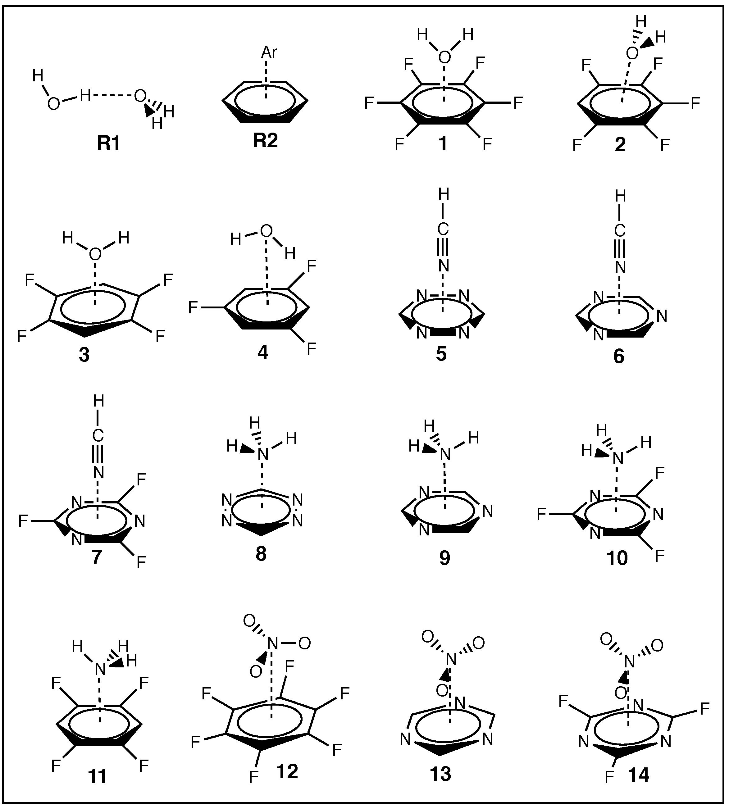
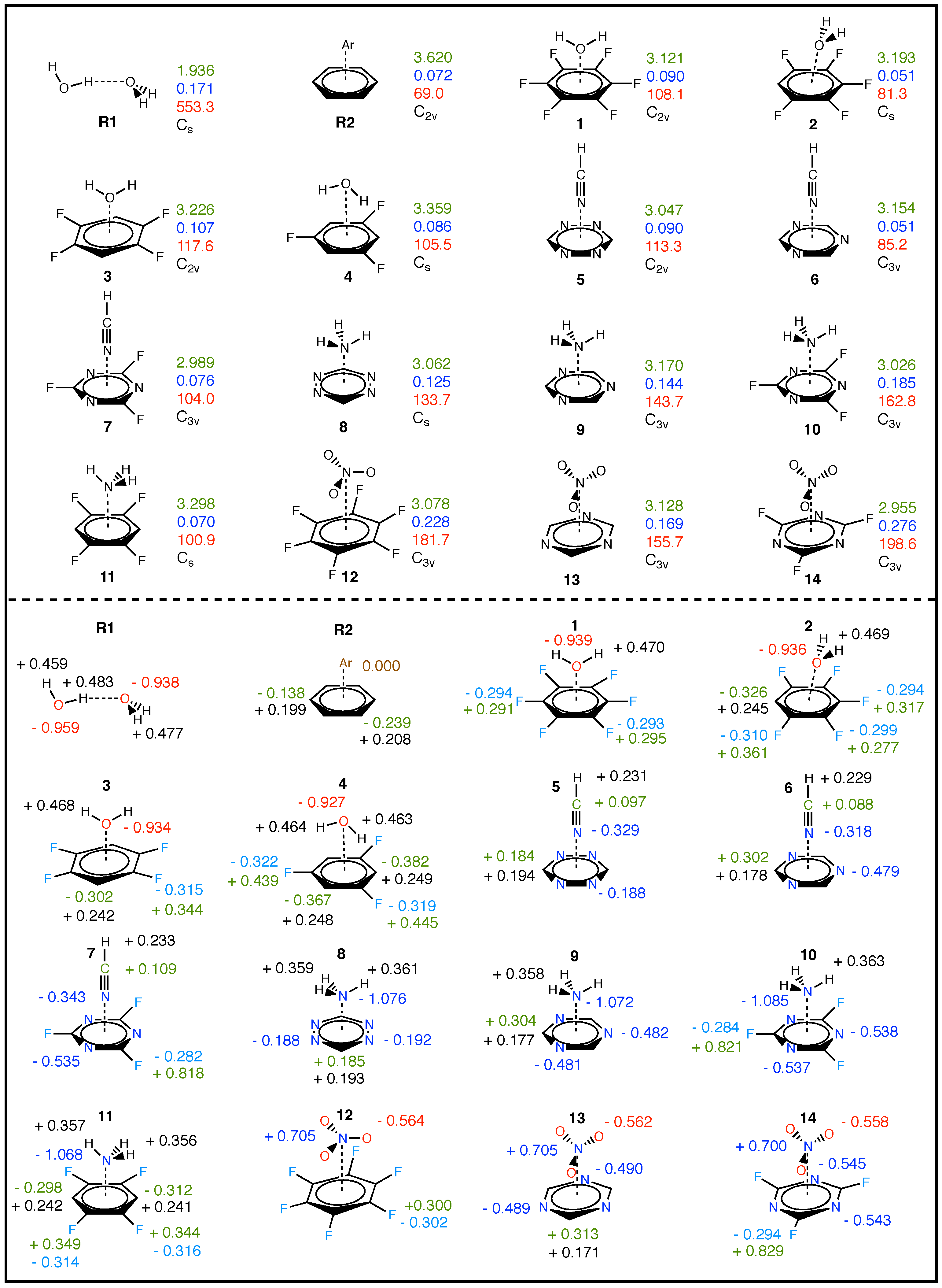
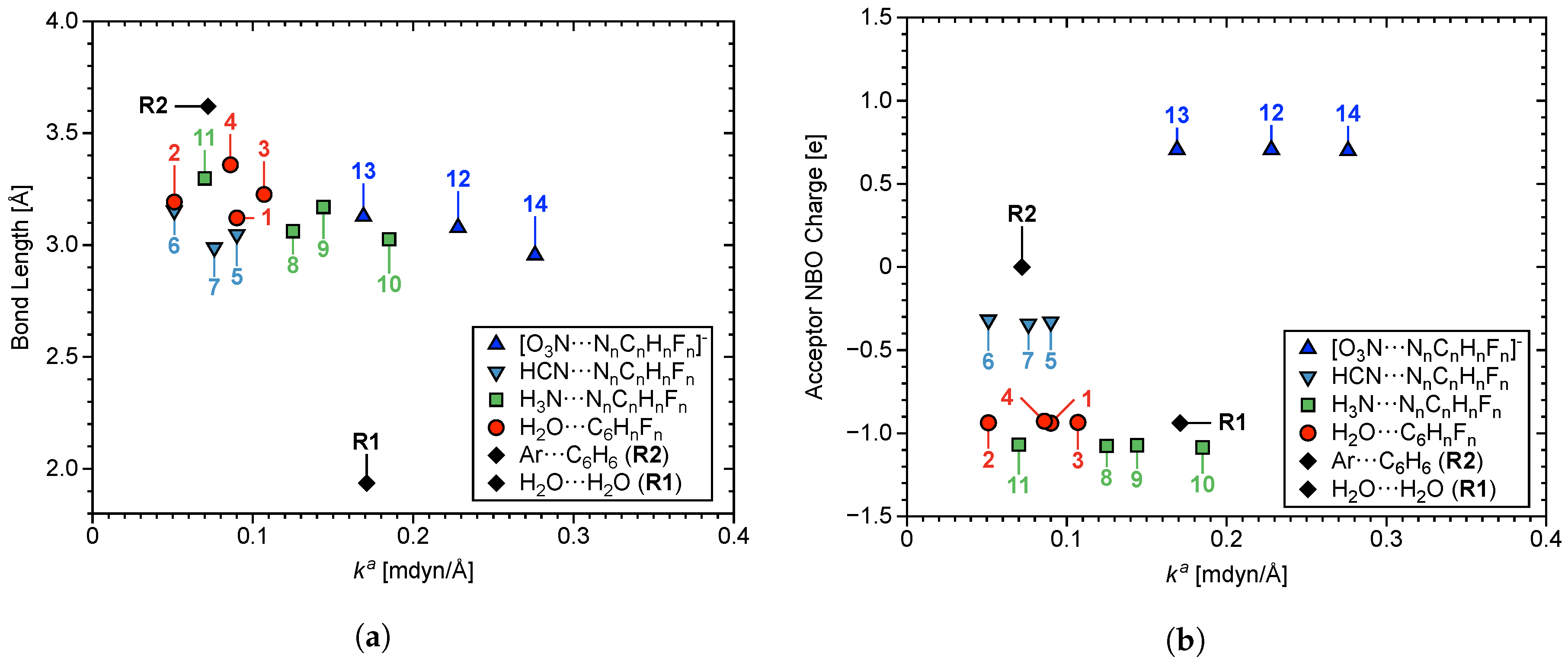
| # | System | Point Group | r | CT lp–Hole | BE | ||
|---|---|---|---|---|---|---|---|
| R1 | H2O···HOH | C | 1.936 | 0.171 | 553.3 | −9.08 | −4.98 |
| R2 | Ar···C6H6 | 3.620 | 0.072 | 69.0 | −0.10 | −0.92 | |
| 1 | H2O···C6F6 | 3.121 | 0.090 | 108.1 | −10.29 | −2.57 | |
| 2 | H2O···C6F5H | C | 3.193 | 0.051 | 81.3 | −7.72 | −2.10 |
| 3 | H2O···C6F4H2 | 3.226 | 0.107 | 117.6 | −5.66 | −1.52 | |
| 4 | H2O···C6F3H3 | C | 3.359 | 0.086 | 105.5 | −1.75 | −2.03 |
| 5 | HCN···N4C2H2 | 3.047 | 0.090 | 113.3 | −30.99 | −2.65 | |
| 6 | HCN···N3C3H3 | 3.154 | 0.051 | 85.2 | −19.93 | −1.75 | |
| 7 | HCN···N3C3F3 | 2.989 | 0.076 | 104.0 | −45.02 | −4.05 | |
| 8 | H3N···N4C2H2 | C | 3.062 | 0.125 | 133.7 | −16.07 | −3.87 |
| 9 | H3N···N3C3H3 | 3.170 | 0.144 | 143.7 | −9.50 | −2.54 | |
| 10 | H3N···N3C3F3 | 3.026 | 0.185 | 162.8 | −2.80 | −5.37 | |
| 11 | H3N···C6F4H2 | C | 3.298 | 0.070 | 100.9 | −8.24 | −2.03 |
| 12 | [O3N···C6F6]− | 3.078 | 0.228 | 181.7 | −5.83 | −12.00 | |
| 13 | [O3N···N3C3H3]− | 3.128 | 0.169 | 155.7 | −6.32 | −6.03 | |
| 14 | [O3N···N3C3F3]− | 2.955 | 0.276 | 198.6 | −11.31 | −13.03 |
| # | Parameter | r | Parameter | r | ||||
|---|---|---|---|---|---|---|---|---|
| 1 | H14···C1 | 3.755 | 0.008 | 124.2 | H15···C6 | 3.755 | 0.008 | 124.2 |
| 4 | H14···C1 | 2.834 | 0.039 | 267.5 | H14···C4 | 2.834 | 0.039 | 267.5 |
| H14···C2 | 2.680 | 0.040 | 270.1 | - | - | - | - | |
| 8 | H10···C6 | 3.534 | 0.014 | 159.8 | H11···N4 | 3.321 | 0.003 | 76.0 |
| H11···N1 | 3.321 | 0.003 | 76.0 | H12···C5 | 3.534 | 0.014 | 159.8 | |
| 9 | H11···N3 | 3.567 | 0.002 | 60.6 | H12···C6 | 3.721 | 0.003 | 72.8 |
| H11···C4 | 3.721 | 0.003 | 71.1 | H13···N1 | 3.567 | 0.002 | 61.7 | |
| H11···C5 | 3.721 | 0.003 | 70.4 | H13···C4 | 3.721 | 0.003 | 72.3 | |
| H12···N2 | 3.567 | 0.002 | 63.0 | H13···C6 | 3.721 | 0.003 | 71.1 | |
| H12···C5 | 3.721 | 0.003 | 73.3 | - | - | - | - | |
| 10 | H11···N3 | 3.431 | 0.016 | 169.2 | H12···C6 | 3.580 | 0.015 | 163.3 |
| H11···C4 | 3.580 | 0.015 | 163.2 | H13···N1 | 3.431 | 0.016 | 169.2 | |
| H11···C5 | 3.580 | 0.015 | 163.3 | H13···C4 | 3.580 | 0.015 | 163.1 | |
| H12···N2 | 3.431 | 0.016 | 169.3 | H13···C6 | 3.580 | 0.015 | 163.3 | |
| H12···C5 | 3.580 | 0.015 | 163.1 | - | - | - | - | |
| 11 | H14···C1 | 3.432 | 0.006 | 108.4 | H16···C2 | 3.585 | 0.005 | 91.9 |
| H14···C2 | 3.585 | 0.005 | 91.9 | H16···C3 | 3.432 | 0.006 | 108.4 | |
| H14···C6 | 3.691 | 0.005 | 91.0 | H16···C4 | 3.691 | 0.005 | 91.0 | |
| 13 | O11···H9 | 3.297 | 0.007 | 108.8 | O13···H8 | 3.297 | 0.007 | 108.6 |
| O12···H7 | 3.297 | 0.007 | 108.3 | - | - | - | - | |
| Units for LVM data are given as follows: r in Å, in mdyn/Å, and in cm. | ||||||||
| # | Parameter | r | Parameter | r | ||||
|---|---|---|---|---|---|---|---|---|
| R2 | Ar13···C1 | 3.877 | 0.031 | 76.0 | Ar13···C4 | 3.877 | 0.031 | 76.0 |
| Ar13···C2 | 3.877 | 0.036 | 80.8 | Ar13···C5 | 3.877 | 0.036 | 80.8 | |
| Ar13···C3 | 3.877 | 0.036 | 80.8 | Ar13···C6 | 3.877 | 0.036 | 80.8 | |
| 1 | O13···C1 | 3.414 | 0.027 | 81.5 | O13···C4 | 3.415 | 0.031 | 87.7 |
| O13···C2 | 3.415 | 0.031 | 87.7 | O13···C5 | 3.415 | 0.031 | 87.7 | |
| O13···C3 | 3.415 | 0.031 | 87.7 | O13···C6 | 3.414 | 0.027 | 81.5 | |
| 2 | O13···C1 | 3.551 | 0.012 | 53.6 | O13···C4 | 3.320 | 0.027 | 81.8 |
| O13···C2 | 3.402 | 0.015 | 61.2 | O13···C5 | 3.551 | 0.012 | 53.6 | |
| O13···C3 | 3.637 | 0.012 | 54.7 | O13···C6 | 3.402 | 0.015 | 61.2 | |
| 3 | O13···C1 | 3.515 | 0.022 | 74.4 | O13···C4 | 3.515 | 0.022 | 74.4 |
| . | O13···C2 | 3.506 | 0.026 | 80.1 | O13···C5 | 3.506 | 0.026 | 80.1 |
| O13···C3 | 3.506 | 0.026 | 80.1 | O13···C6 | 3.506 | 0.026 | 80.1 | |
| 5 | N9···C1 | 3.342 | 0.044 | 102.9 | N9···C4 | 3.342 | 0.044 | 102.9 |
| N9···C2 | 3.342 | 0.044 | 102.9 | N9···C5 | 3.279 | 0.047 | 111.6 | |
| N9···C3 | 3.342 | 0.044 | 102.9 | N9···C6 | 3.279 | 0.047 | 111.6 | |
| 6 | N10···N1 | 3.437 | 0.024 | 75.9 | N10···C4 | 3.405 | 0.025 | 80.6 |
| N10···N2 | 3.437 | 0.024 | 75.8 | N10···C5 | 3.405 | 0.025 | 80.5 | |
| N10···N3 | 3.437 | 0.024 | 76.6 | N10···C6 | 3.405 | 0.024 | 80.2 | |
| 7 | N10···N1 | 3.288 | 0.038 | 95.8 | N10···C4 | 3.240 | 0.038 | 100.1 |
| N10···N2 | 3.288 | 0.038 | 95.7 | N10···C5 | 3.240 | 0.038 | 100.0 | |
| N10···N3 | 3.288 | 0.038 | 95.7 | N10···C6 | 3.240 | 0.038 | 100.1 | |
| 8 | N9···N1 | 3.316 | 0.059 | 119.5 | N9···N4 | 3.316 | 0.059 | 119.5 |
| N9···N2 | 3.398 | 0.045 | 104.0 | N9···C5 | 3.290 | 0.063 | 128.1 | |
| N9···N3 | 3.398 | 0.045 | 104.0 | N9···C6 | 3.290 | 0.063 | 128.1 | |
| 9 | N10···N1 | 3.452 | 0.049 | 108.5 | N10···C4 | 3.419 | 0.056 | 121.2 |
| N10···N2 | 3.452 | 0.049 | 109.1 | N10···C5 | 3.419 | 0.055 | 120.2 | |
| N10···N3 | 3.452 | 0.048 | 108.0 | N10···C6 | 3.419 | 0.054 | 119.4 | |
| 10 | N10···N1 | 3.222 | 0.074 | 133.8 | N10···C4 | 3.273 | 0.076 | 140.9 |
| N10···N2 | 3.222 | 0.074 | 133.9 | N10···C5 | 3.273 | 0.076 | 140.9 | |
| N10···N3 | 3.222 | 0.074 | 133.8 | N10···C6 | 3.273 | 0.076 | 140.9 | |
| 11 | N13···C1 | 3.557 | 0.021 | 74.6 | N13···C4 | 3.587 | 0.022 | 76.3 |
| N13···C2 | 3.552 | 0.036 | 97.3 | N13···C5 | 3.611 | 0.041 | 103.7 | |
| N13···C3 | 3.557 | 0.021 | 74.6 | N13···C6 | 3.587 | 0.022 | 76.3 | |
| 12 | N13···C1 | 3.375 | 0.031 | 90.6 | O14···C1 | 3.149 | 0.015 | 61.2 |
| N13···C2 | 3.375 | 0.031 | 90.6 | O14···C5 | 3.149 | 0.015 | 61.2 | |
| N13···C3 | 3.375 | 0.031 | 90.6 | O15···C2 | 3.149 | 0.015 | 61.2 | |
| N13···C4 | 3.375 | 0.031 | 90.6 | O15···C6 | 3.149 | 0.015 | 61.2 | |
| N13···C5 | 3.375 | 0.031 | 90.6 | O16···C3 | 3.149 | 0.015 | 61.2 | |
| N13···C6 | 3.375 | 0.031 | 90.6 | O16···C4 | 3.149 | 0.015 | 61.2 | |
| 13 | N10···N1 | 3.419 | 0.022 | 72.3 | O11···C4 | 3.117 | 0.017 | 64.1 |
| N10···N2 | 3.419 | 0.022 | 72.4 | O12···N1 | 3.394 | 0.016 | 59.7 | |
| N10···N3 | 3.419 | 0.021 | 72.0 | O12···N2 | 3.394 | 0.016 | 59.7 | |
| N10···C4 | 3.375 | 0.021 | 73.8 | O12···C5 | 3.117 | 0.017 | 64.0 | |
| N10···C5 | 3.375 | 0.021 | 73.5 | O13···N2 | 3.394 | 0.016 | 59.6 | |
| N10···C6 | 3.375 | 0.021 | 73.7 | O13···N3 | 3.394 | 0.016 | 59.5 | |
| O11···N1 | 3.394 | 0.016 | 59.6 | O13···C6 | 3.117 | 0.017 | 64.1 | |
| O11···N3 | 3.394 | 0.016 | 59.4 | - | - | - | - | |
| 14 | N10···C4 | 3.205 | 0.134 | 187.7 | O11···C4 | 2.936 | 0.028 | 83.6 |
| N10···C5 | 3.205 | 0.134 | 187.7 | O11···C5 | 2.936 | 0.028 | 83.6 | |
| N10···C6 | 3.205 | 0.134 | 187.7 | O11···C6 | 2.936 | 0.028 | 83.6 | |
| Units for computational data are given as follows: r in Å, in mdyn/Å, and in cm. | ||||||||
© 2020 by the authors. Licensee MDPI, Basel, Switzerland. This article is an open access article distributed under the terms and conditions of the Creative Commons Attribution (CC BY) license (http://creativecommons.org/licenses/by/4.0/).
Share and Cite
Yannacone, S.; Freindorf, M.; Tao, Y.; Zou, W.; Kraka, E. Local Vibrational Mode Analysis of π–Hole Interactions between Aryl Donors and Small Molecule Acceptors. Crystals 2020, 10, 556. https://0-doi-org.brum.beds.ac.uk/10.3390/cryst10070556
Yannacone S, Freindorf M, Tao Y, Zou W, Kraka E. Local Vibrational Mode Analysis of π–Hole Interactions between Aryl Donors and Small Molecule Acceptors. Crystals. 2020; 10(7):556. https://0-doi-org.brum.beds.ac.uk/10.3390/cryst10070556
Chicago/Turabian StyleYannacone, Seth, Marek Freindorf, Yunwen Tao, Wenli Zou, and Elfi Kraka. 2020. "Local Vibrational Mode Analysis of π–Hole Interactions between Aryl Donors and Small Molecule Acceptors" Crystals 10, no. 7: 556. https://0-doi-org.brum.beds.ac.uk/10.3390/cryst10070556