Formation of Three-Dimensional Electronic Networks Using Axially Ligated Metal Phthalocyanines as Stable Neutral Radicals


Department of Chemistry, Kumamoto University, 2-39-1 Kurokami, Kumamoto 860-8555, Japan
*
Author to whom correspondence should be addressed.
Crystals 2020, 10(9), 747; https://0-doi-org.brum.beds.ac.uk/10.3390/cryst10090747
Submission received: 3 August 2020
/
Revised: 19 August 2020
/
Accepted: 21 August 2020
/
Published: 24 August 2020
(This article belongs to the Special Issue Organic Conductors)
Abstract
:Organic π-radical crystals are potential single-component molecular conductors, as they involve charge carriers. We fabricated new organic π-radical crystals using axially ligated metal phthalocyanine anions ([MIII(Pc)L2]−) as starting materials. Electrochemical oxidation of [MIII(Pc)L2]− afforded single crystals of organic π-radicals of the type MIII(Pc)Cl2·THF (M = Co or Fe, THF = tetrahydrofuran), where the π-conjugated macrocyclic phthalocyanine ligand is one-electron oxidized. The X-ray crystal structure analysis revealed that MIII(Pc)Cl2 formed three-dimensional networks with π-π overlaps. The electrical resistivities of CoIII(Pc)Cl2·THF and FeIII(Pc)Cl2·THF at room temperature along the a-axis were 6 × 10² and 6 × 10³ Ω cm, respectively, and were almost isotropic, meaning that MIII(Pc)Cl2·THF had three-dimensional electronic systems.
1. Introduction
Ordinary organic radicals are unstable due to their high chemical reactivity, which is caused by the presence of an unpaired electron. However, organic radicals can be considered to have charge carriers, because their highest occupied molecular orbital (HOMO) is singly occupied, leading to a half-filled band in the solid state. Recently, a nonconjugated organic radical crystal has been reported to be conductive, although the conductivity is low in the solid state [1]. This might be due to the low degree of intermolecular overlap for the molecular orbital in which the radical lies. On the other hand, organic π-radicals tend to stack with significant overlap between adjacent molecules, giving rise to conducting pathways. For this reason, organic π-radicals have attracted significant interest from those studying molecular conductors, and it has been reported that despite the expected half-filled band, most organic π-radical crystals behave as Mott insulators because of the larger on-site Coulomb repulsion energy (U) compared to the transfer energy (t) [2,3]. However, external changes such as pressure can control the competition between U and t, leading to drastic phase transitions from the insulating state to metallic or superconducting states being reported for various molecular Mott insulators [3,4]. This means that if a stable neutral π-radical crystal is fabricated, it could be possible to obtain a single-component molecular conductor, which is a hot topic in the study of molecular crystals [5,6,7,8,9].
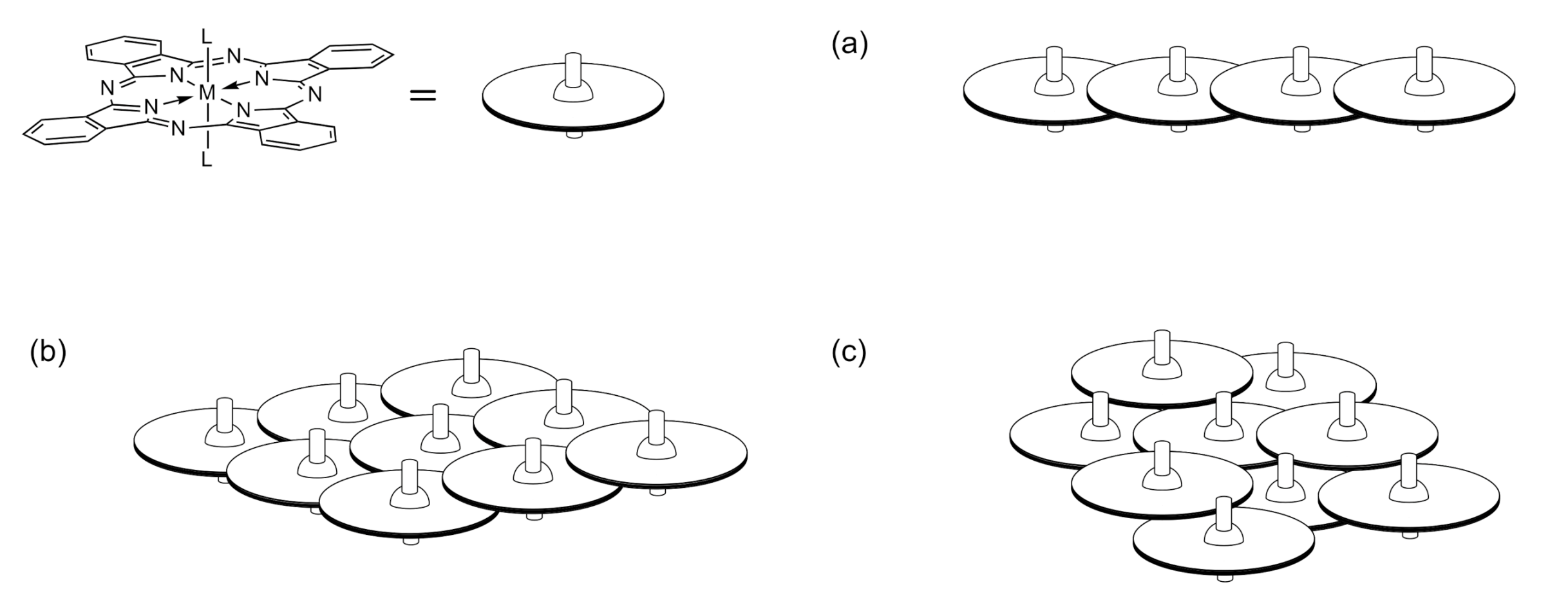
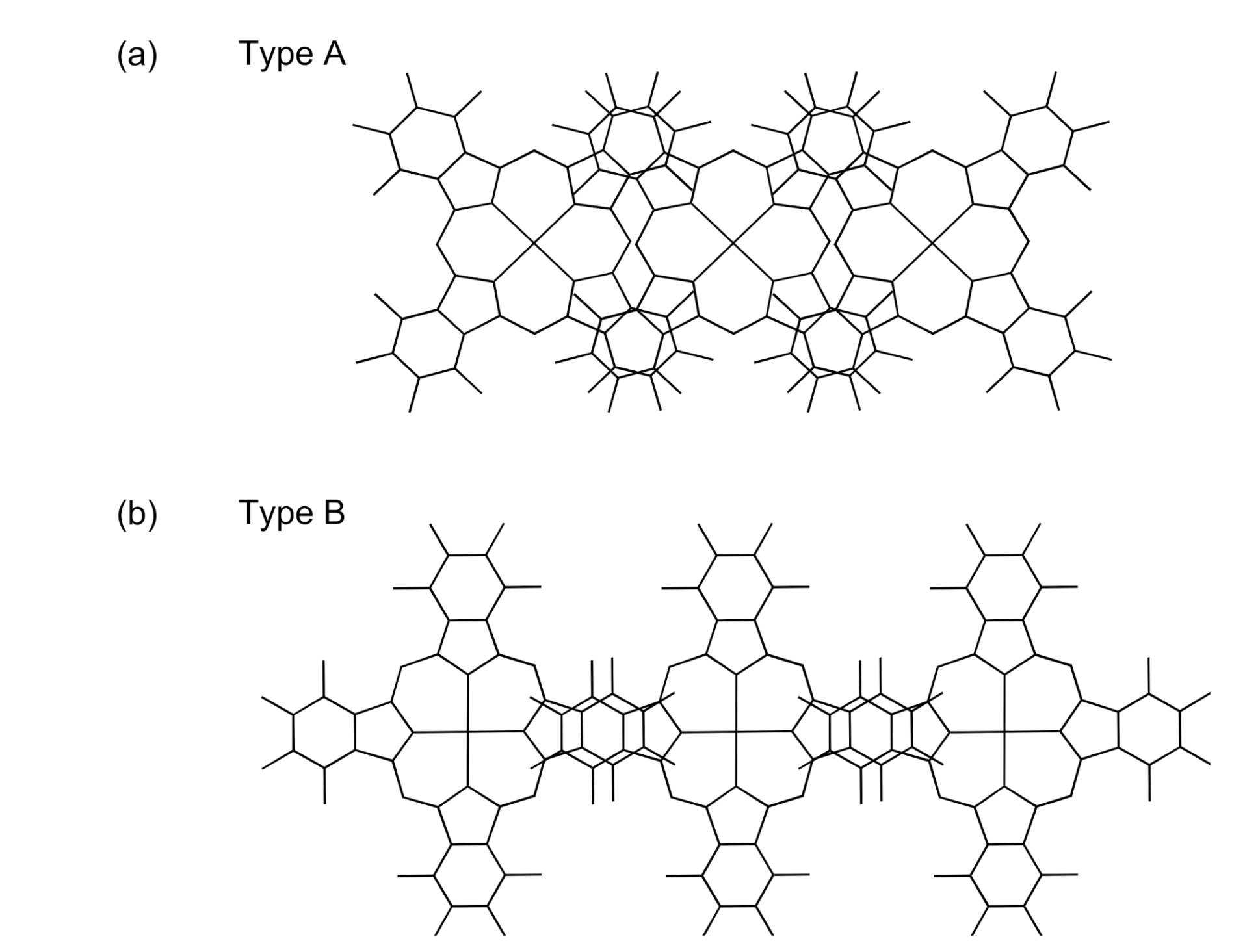
Axially ligated metal phthalocyanine anions ([MIII(Pc)L2]−) are attractive components for the construction of neutral π-radical crystals as single-component molecular conductors, because the wide π-conjugated system of phthalocyanine (Pc) might suppress U. Inabe expected that the electrochemical oxidation of the π-conjugated macrocyclic ligand in [MIII(Pc)L2]− would give rise to conducting crystals, while the MIII(Pc)L2 unit could impart many kinds of dimensionality to the molecular arrangement as the axial ligand induces slipped stacks (Figure 1) [10]. Indeed, it was found that there were two different types of π-π overlaps between the MIII(Pc)L2 units (Figure 2). Although the π-π overlaps are significantly reduced compared to those seen in M(Pc)X-type conductors having face-to-face stacking (the overlap integral of type A is about 40% of that of M(Pc)X-type conductors) [11], it is enough for electrical conduction. Consequently, a large number of molecular conducting crystals composed of MIII(Pc)L2 units were fabricated, including π-neutral radical crystals as well as crystals of highly conducting partially oxidized salts, with molecular arrangements showing the formation of one-dimensional, two-dimensional, and also three-dimensional networks [12,13,14]. Although all π-neutral radical crystals composed of MIII(Pc)L2 are Mott insulators, their resistivities are relatively small.
Herein, we focused on the dimensionality of MIII(Pc)L2 crystals. It has been reported that the conductivity of MIII(Pc)L2 radical crystals tends to increase as the dimensionality of the network is increased [14]; the first example of a three-dimensional neutral radical crystal of CoIII(Pc)(CN)2·2H2O exhibited a resistivity at room temperature of no more than 100 Ω cm with an activation energy of less than 0.1 eV [10]. However, only a few examples of three-dimensional systems exist at present [14]. We have fabricated a new three-dimensional system consisting of neutral radical crystals of MIII(Pc)Cl2·THF (M = Co or Fe, THF = tetrahydrofuran). In this paper, the crystal structures and electrical properties of MIII(Pc)Cl2·THF are reported.
2. Materials and Methods
2.1. Materials
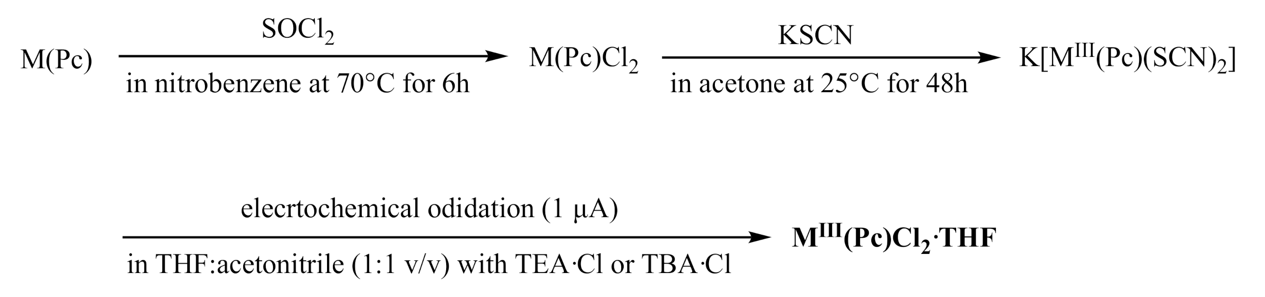
CoII(Pc) and FeII(Pc) were prepared by refluxing CoCl2·6H2O or FeCl2·4H2O with four molar equivalents of 1,2-dicyanobenzene in quinoline, and CoII(Pc) or FeII(Pc) (3.0 g, 5.2 mmol) was treated with SOCl2 (5 mL, 69 mmol) in nitrobenzene (70 mL) at 70 °C for 6 h to produce CoIII(Pc)Cl2 (yield 3.2 g, 5.0 mmol, 95%) or FeIII(Pc)Cl2 (yield 2.1 g, 3.3 mmol, 62%) [15,16]. Then, K[MIII(Pc)(SCN)2] was prepared according to the literature [16,17], by reacting MIII(Pc)Cl2 (2.0 g, 3.1 mmol) with KSCN (6.0 g, 62 mmol) in acetone (200 mL) at 25 °C for 48 h (yield 2.1 g, 2.9 mmol, 94%).
Electrochemical oxidation of K[MIII(Pc)(SCN)2] (30 mg) with two equivalents of tetraethylammonium chloride or tetrabutylammonium chloride was performed under a constant current of 1 μA in a THF:acetonitrile (30 mL, 1:1 v/v) solution at 25 °C using an electrocrystallization cell equipped with a glass frit between the two compartments, and yielded black square-pillar crystals of MIII(Pc)Cl2·THF on the anode. The typical size of the crystals obtained was between 0.5 × 0.3 × 0.3 mm3 and 1.0 × 0.5 × 0.5 mm3. The obtained radical crystals were stable, and no decomposition was detected in the X-ray crystal structures or electrical resistivity measurements over several months. The Schematic route for the synthesis is shown in Figure 3.
2.2. X-ray Crystal Structure Determination
Crystal data for M(Pc)Cl2·THF were collected at 298 K using an automated Rigaku SuperNova system (Rigaku, Tokyo, Japan) with monochromated Mo-Kα radiation (λ = 0.71073 Å). The structure was solved by using SIR2019 [18,19], and was refined by a full-matrix least-squares technique with SHELXL-2018/1 [20] using anisotropic and isotropic thermal parameters for non-hydrogen and hydrogen atoms, respectively. Orientational disorder was observed for the solvent site (THF molecule). We assigned C and O atoms according to the bond lengths.
Crystal data for Co(Pc)Cl2·THF at 298 K: Formula, C36H24Cl2CoN8O, Formula weight 714.46, monoclinic, P21/n (#14), a = 8.2526(2), b = 15.4184(6) Å, c = 11.8762(4) Å, β = 92.996(3)°, V = 1509.08(9) Å3, Z = 2, dcal = 1.572 g cm−3, μ (MoKα) = 0.793 mm−1 (λ = 0.71073 Å), R1 = 0.0545, wR2 = 0.1852, GoF = 1.280. CCDC 2013803.
Crystal data for Fe(Pc)Cl2·THF at 298 K: Formula, C36H24Cl2FeN8O, Formula weight 711.38, monoclinic, P21/n (#14), a = 8.2062(1), b = 15.4115(1) Å, c = 11.9043(1) Å, β = 93.2238(9)°, V = 1503.15(2) Å3, Z = 2, dcal = 1.572 g cm−3, μ (MoKα) = 0.727 mm−1 (λ = 0.71073 Å), R1 = 0.0435, wR2 = 0.1797, GoF = 1.503. CCDC 2013804.
CCDC 2013803 and 2013804 contain the supplementary crystallographic data for this paper. These data can be obtained free of charge via http://www.ccdc.cam.ac.uk/conts/retrieving.html (or from the CCDC, 12 Union Road, Cambridge CB2 1EZ, UK; Fax: +44-1223-336033; E-mail: [email protected]).
Extended Hückel calculations were performed using a CAESAR 2 software package (Prime Color Software, Inc., Charlotte, NC, USA) with the atomic parameters determined by the X-ray structure analysis. Default parameters were used.
2.3. Measurements
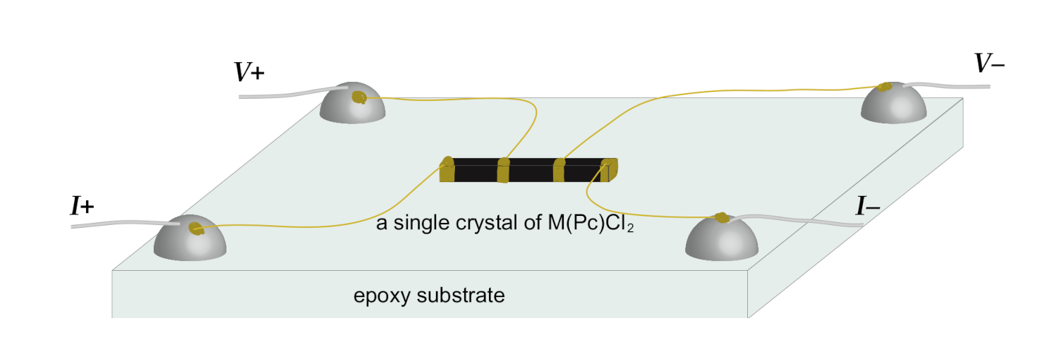
Electrical resistivity measurements along the a-axis of MIII(Pc)Cl2·THF single crystals were performed by the standard four-probe method. The two-probe method was also adopted for the measurement with the current parallel and perpendicular to the a-axis. The electrical leads, which were gold wires with diameters of 25 μm, were attached to the crystal face using gold paste (Figure 4). The data are typical, as the resistivity and activation energies varied slightly depending on the individual crystal examined. However, we confirmed the reproducibility of the data by examining several crystals of both materials.
3. Results
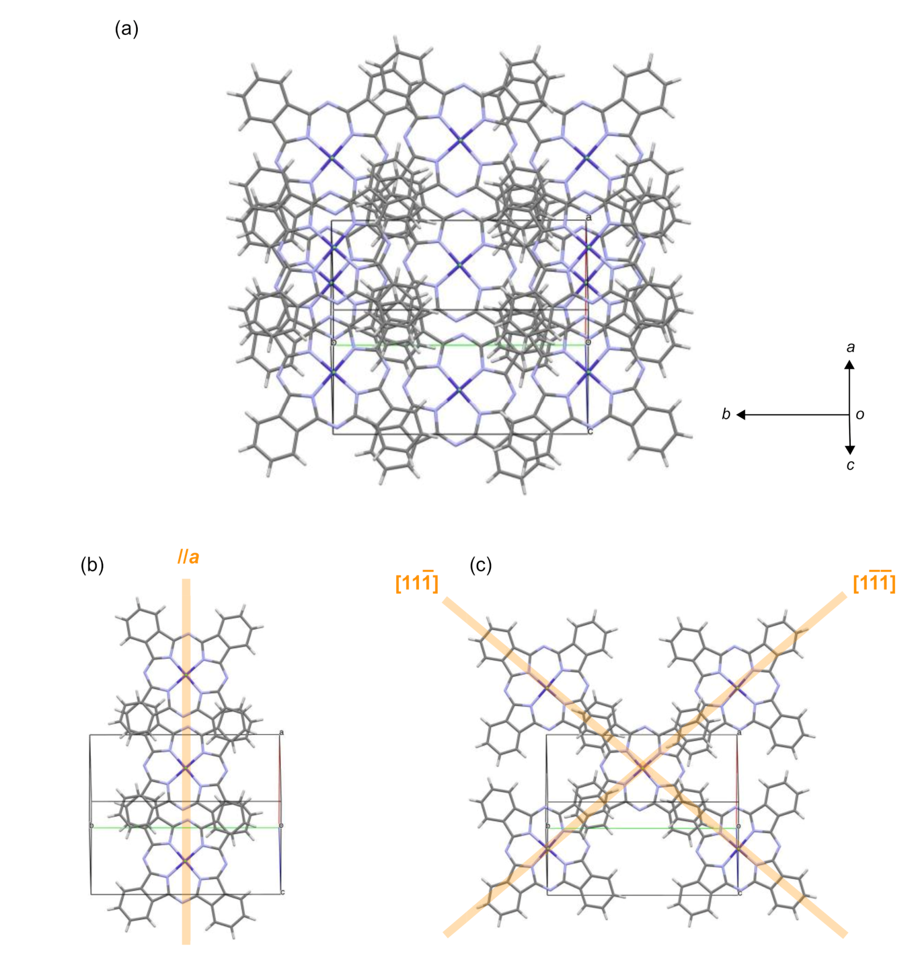
CoIII(Pc)Cl2·THF and FeIII(Pc)Cl2·THF were found to have a monoclinic unit cell with the P21/n space group, and were isostructural to each other (Table 1). Similar isostructural natures have been reported for M(Pc)L2-based conductors [21,22,23], because the rigid geometry of the Pc framework is insensitive to the central ion. Figure 5 shows the crystal structure of CoIII(Pc)Cl2·THF. Because the oxidation potentials of CoIII and FeIII are higher than that of Pc2– [10,24], the Pc ligand is oxidized to Pc•–, meaning MIII(Pc)Cl2·THF is a neutral π-radical. The MIII(Pc)Cl2 units form one-dimensional stacks along the a-axis via interactions between two peripheral benzene rings per unit, with interplanar distances of 3.49 and 3.54 Å (type A), and also form additional stacks along the [11] and [1] directions with one peripheral benzene ring per unit (type B) with interplanar distances of 3.43 and 3.44 Å, respectively, resulting in the formation of three-dimensional networks. To evaluate the effectiveness of the stacking, the overlap integrals between the HOMOs of adjacent Pcs along each stacking direction were calculated by the extended Hückel method based on the structural data (Table 2). Because the intermolecular overlap integral is usually regarded as being proportional to transfer energy, the estimation of the overlap integrals can be a useful index for investigating the anisotropies of molecular stacks [25], and it was found that the overlap integrals along the a-axis of type A stacks were almost twice those seen in other stacks.
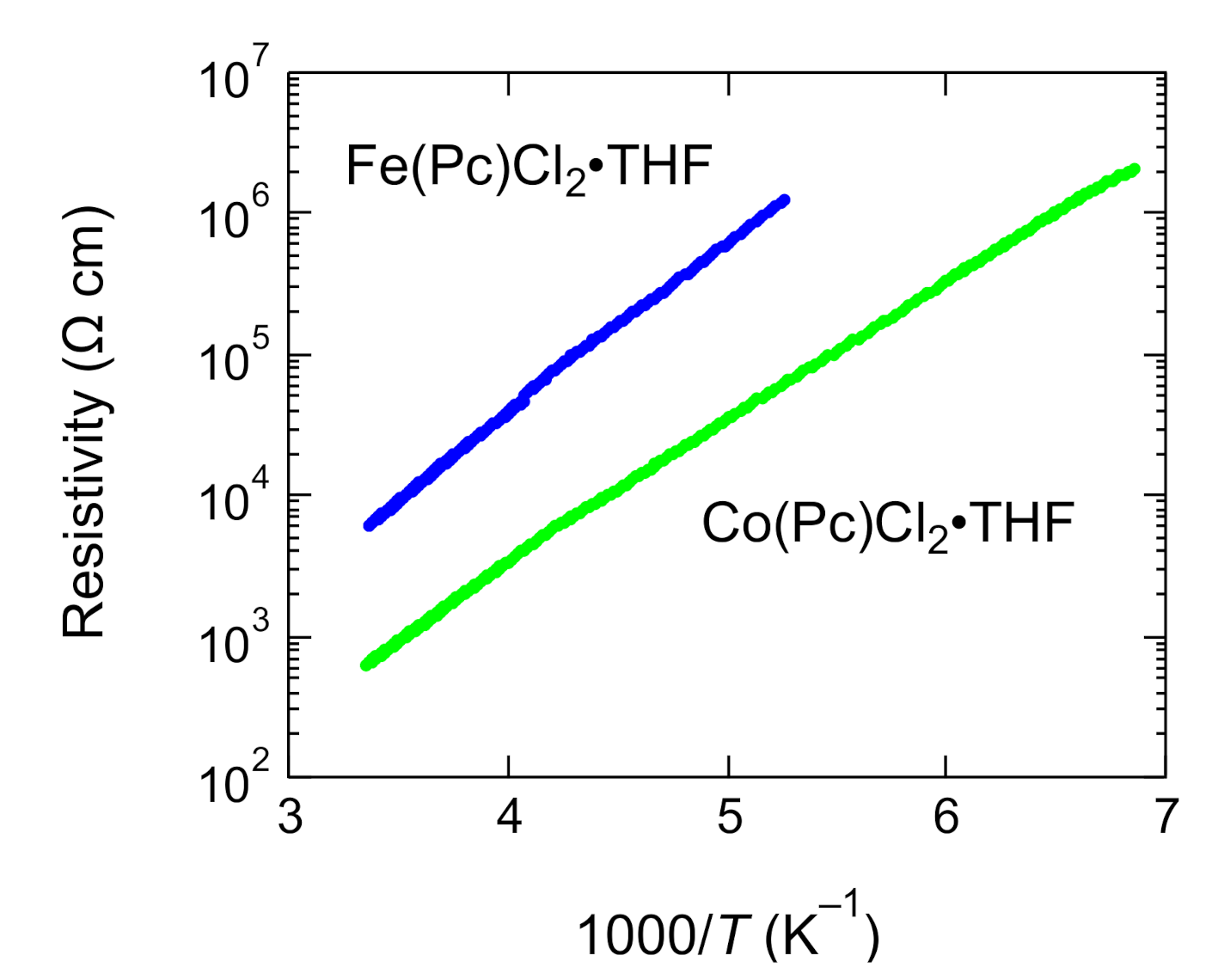
Figure 6 shows the temperature dependences of the electrical resistivities along the a-axes of CoIII(Pc)Cl2·THF and FeIII(Pc)Cl2·THF. The electrical resistivities of CoIII(Pc)Cl2·THF and FeIII(Pc)Cl2·THF at room temperature were 6.3 × 10² and 6.1 × 10³ Ω cm, respectively, and both systems showed semi-conducting behavior, with activation energies of 0.20 eV for CoIII(Pc)Cl2·THF and 0.24 eV for FeIII(Pc)Cl2·THF.
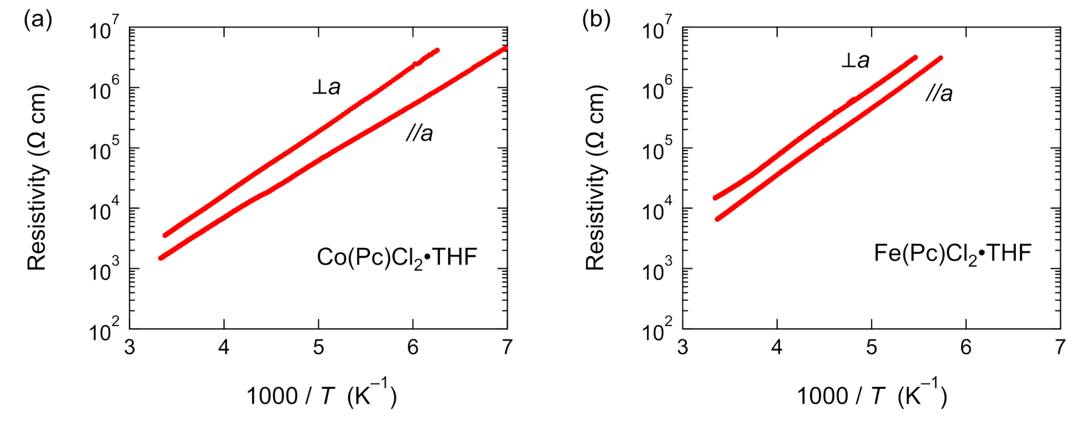
Figure 7 shows the temperature dependences of the electrical resistivities of CoIII(Pc)Cl2·THF and FeIII(Pc)Cl2·THF along the a-axis (//a) and perpendicular to the a-axis (⊥a), as measured by the two-probe method. In both systems, the resistivity along the a-axis was smaller than that perpendicular to the a-axis, reflecting the difference in the overlap integrals; however, the current-direction dependence of the electrical resistivity was less than one order of magnitude. The activation energies of CoIII(Pc)Cl2·THF and FeIII(Pc)Cl2·THF were almost independent of the direction of conduction.
4. Discussions
Despite the isostructural nature of the two compounds, the electrical resistivity of FeIII(Pc)Cl2·THF was almost one order of magnitude higher than that of CoIII(Pc)Cl2·THF, and the activation energy was also higher. Similar enhancements of the electrical resistivity and activation energy have been reported for molecular conductors based on MIII(Pc)L2 [21,22,23], and could be attributable to the different magnetic moments of the central metal ions. Low-spin FeIII has a magnetic moment of S = 1/2, while low-spin CoIII has no magnetic moment (S = 0), and it has been reported that the magnetic moment enhances the electrical resistivity [26].
As shown in Figure 7, the electrical resistivity of MIII(Pc)Cl2·THF depended on the current direction; however, the difference was quite small. In one- or two-dimensional systems, the resistivity along the stacking direction(s) was two orders of magnitude smaller than that perpendicular to the stacking direction(s) [27]. Therefore, the almost isotropic nature observed in the resistivity measurements in this study demonstrates that MIII(Pc)Cl2·THF had a three-dimensional electronic system. However, the electrical resistivity of CoIII(Pc)Cl2·THF at room temperature (6.3 × 10² Ω cm) was two orders of magnitude higher than that of CoIII(Pc)(CN)2·2H2O, which was the first example of a three-dimensional neutral π-radical crystal of the type MIII(Pc)L2 [10]. The activation energy of MIII(Pc)Cl2·THF was also higher than that of CoIII(Pc)(CN)2·2H2O. Therefore, we calculated the overlap integrals of CoIII(Pc)(CN)2·2H2O based on the reported crystal data, and compared the results with the overlap integrals of CoIII(Pc)Cl2·THF (Table 3). Although the molecular arrangement of MIII(Pc)Cl2 in MIII(Pc)Cl2·THF appeared to be similar to that of CoIII(Pc)(CN)2 in CoIII(Pc)(CN)2·2H2O, the overlap integrals of CoIII(Pc)(CN)2·2H2O were quite different from those of MIII(Pc)Cl2·THF. The overlap integral along the c-axis, where CoIII(Pc)(CN)2 formed a type A one-dimensional stack, was 5.7 × 10⁻³, while the overlap integrals along the [112] and [12] directions, where CoIII(Pc)(CN)2 formed type B stacks, were 1.7 × 10⁻³. These values were more than twice those obtained for CoIII(Pc)Cl2·THF. These discrepancies could be the cause of the difference in the electrical properties, meaning that slight changes in molecular arrangements could lead to drastic changes in the electrical properties in the neutral π-radical crystals composed of MIII(Pc)L2.
5. Conclusions
We succeeded in fabricating single crystals of stable organic π-radicals of the type MIII(Pc)Cl2·THF (M = Co or Fe, THF = tetrahydrofuran). The overlap integrals between the HOMOs of adjacent Pcs were calculated based on the atomic parameters determined by the X-ray crystal structural analyses, and it was revealed that MIII(Pc)Cl2 formed three-dimensional networks. Furthermore, the electrical resistivities measured were almost independent of the applied current direction, meaning that MIII(Pc)Cl2·THF had three-dimensional electronic systems, which are rarely observed in the study of molecular conductors. The resistivities of CoIII(Pc)Cl2·THF and FeIII(Pc)Cl2·THF at room temperature were 6 × 10² and 6 × 10³ Ω cm, respectively. These are similar to or significantly smaller than those reported for neutral radical conductors showing pressure-induced metallization [6,8], indicating that further study of three-dimensional Mott insulators composed of MIII(Pc)L2 under the application of pressure could allow for phase transitions from insulating to metallic or superconducting states. Furthermore, it was revealed that a slight change in molecular arrangement led to drastic changes in the electrical properties. As MIII(Pc)L2 shows various stacking types depending on the fabrication conditions, there is a strong possibility that new single-component molecular conductors composed of MIII(Pc)L2 could be produced.
Author Contributions
Conceptualization, R.S. and M.M.; methodology, R.S.; software, R.S.; formal analysis, M.M.; writing—original draft preparation, M.M.; writing—review and editing, R.S. and M.M.; visualization, M.M.; supervision, M.M.; project administration, M.M.; funding acquisition, M.M. All authors have read and agreed to the published version of the manuscript.
Funding
This research was funded by a Grant-in-Aid for Scientific Research (B), grant number 19H02691, from the Japan Society for the Promotion of Science.
Acknowledgments
We dedicate this study to Tamotsu Inabe. We thank Akira Yoshiasa at Kumamoto University for his help with the X-ray diffraction measurements.
Conflicts of Interest
The authors declare no conflict of interest.
References
- Yu, I.; Jo, Y.; Ko, J.; Kim, D.-Y.; Sohn, D.; Joo, Y. Making nonconjugated small-molecule organic radicals conduct. Nano Lett. 2020, 20, 5376–5382. [Google Scholar] [CrossRef] [PubMed]
- Jérome, D. Organic conductors: From charge density wave TTF-TCNQ to superconducting (TMTSF)2PF6. Chem. Rev. 2004, 104, 5565–5591. [Google Scholar] [CrossRef] [PubMed]
- Saito, G.; Yoshida, Y. Development of conductive organic molecular assemblies: Organic metals, superconductors, and exotic functional materials. Bull. Chem. Soc. Jpn. 2007, 80, 1–137. [Google Scholar] [CrossRef]
- Ishiguro, T.; Yamaji, K.; Saito, G. Organic Superconductors, 2nd ed.; Springer: Berlin, Germany, 1998. [Google Scholar]
- Wong, J.W.L.; Mailman, A.; Lekin, K.; Winter, S.M.; Yong, W.; Zhao, J.; Garimella, S.V.; Tse, J.S.; Secco, R.A.; Desgreniers, S.; et al. Pressure induced phase transitions and metallization of a neutral radical conductor. J. Am. Chem. Soc. 2014, 136, 1070–1081. [Google Scholar] [CrossRef]
- Tian, D.; Winter, S.M.; Mailman, A.; Wong, J.W.L.; Yong, W.; Yamaguchi, H.; Jia, Y.; Tse, J.S.; Desgreniers, S.; Secco, R.A.; et al. The metallic state in neutral radical conductors: Dimensionality, pressure and multiple orbital effects. J. Am. Chem. Soc. 2015, 137, 14136–14148. [Google Scholar] [CrossRef] [Green Version]
- Souto, M.; Cui, H.B.; Peña-Álvarez, M.; Baonza, V.G.; Jeschke, H.O.; Tomic, M.; Valenti, R.; Blasi, D.; Ratera, I.; Rovira, C.; et al. Pressure-induced conductivity in a neutral nonplanar spin-localized radical. J. Am. Chem. Soc. 2016, 138, 11517–11525. [Google Scholar] [CrossRef] [Green Version]
- Souto, M.; Gullo, M.C.; Cui, H.B.; Casati, N.; Montisci, F.; Jeschke, H.O.; Valenti, R.; Ratera, I.; Rovira, C.; Veciana, J. Role of the open-shell character on the pressure-induced conductivity of an organic donor-acceptor radical dyad. Chem. Eur. J. 2018, 24, 5500–5505. [Google Scholar] [CrossRef]
- Isono, T.; Kamo, H.; Ueda, A.; Takahashi, K.; Nakao, A.; Kumai, R.; Nakao, H.; Kobayashi, K.; Murakami, Y.; Mori, H. Hydrogen bond-promoted metallic state in a purely organic single-component conductor under pressure. Nat. Commun. 2013, 4, 1344. [Google Scholar] [CrossRef] [Green Version]
- Inabe, T.; Maruyama, Y. Multi-dimensional stacking structure in phthalocyanine-based electrical conductors, K[Co(phthalocyaninato)(CN)2]2·5CH3CN and Co(phthalocyaninato)(CN)2·2H2O. Bull. Chem. Soc. Jpn. 1990, 63, 2273–2280. [Google Scholar] [CrossRef] [Green Version]
- Hasegawa, H.; Naito, T.; Inabe, T.; Akutagawa, T.; Nakamura, T. A highly conducting partially oxidized salt of axially substituted phthalocyanine. Structure and physical properties of TPP[Co(Pc)(CN)2]2 {TPP = tetraphenylphosphonium, [Co(Pc)(CN)2] = dicyano(phthalocyaninato)cobalt(III)}. J. Mater. Chem. 1998, 8, 1567–1570. [Google Scholar] [CrossRef]
- Inabe, T.; Tajima, H. Phthalocyanines–Versatile components of molecular conductors. Chem. Rev. 2004, 104, 5503–5533. [Google Scholar] [CrossRef]
- Inabe, T. Design of functional molecular crystal by controlling intermolecular interactions. Bull. Chem. Soc. Jpn. 2005, 78, 1373–1383. [Google Scholar] [CrossRef]
- Inabe, T.; Ishikawa, M.; Asari, T.; Hasegawa, H.; Fujita, A.; Matsumura, N.; Naito, T.; Matsuda, M.; Tajima, H. Phthalocyanine conductors: New trend for crystal and functionality design. Mol. Cryst. Liq. Cryst. 2006, 455, 87–92. [Google Scholar] [CrossRef] [Green Version]
- Myers, J.F.; Canham, G.W.R.; Lever, A.B.P. Higher oxidation level phthalocyanine complexes of chromium, iron, cobalt, and zinc. Phthalocyanine radical species. Inorg. Chem. 1975, 14, 461–468. [Google Scholar] [CrossRef]
- Yu, D.E.C. Synthesis of Axially-Ligated Metallophthalocaynine Molecular Conductors and the Chemical and Physical Factors Affecting Their Solid-State Properties. Ph.D. Thesis, Hokkaido University, Sapporo, Japan, 2008. [Google Scholar]
- Hedtmann-Rein, C.; Hanack, M.; Peters, K.; Peters, E.-M.; Schnering, H.G. Synthesis and properties of (phthlaocyaninato) and (tetrabenzoporphyrinato)cobalt(III) thiocyanate and isothiocyanate compounds. Crystal and molecular structures of (phthalocyaninato)(pyridine)(thiocyanato)cobalt(III). Inorg. Chem. 1987, 26, 2647–2651. [Google Scholar] [CrossRef]
- Sir 2019. Available online: http://www.ba.ic.cnr.it/softwareic/sir/ (accessed on 25 May 2020).
- Burla, M.C.; Caliandro, R.; Carrozzini, B.; Cuocci, C.; Mallamo, M.; Mazzone, A.; Polidori, G. Crystal structure determination and refinement via SIR 2014. J. Appl. Cryst. 2015, 48, 306–309. [Google Scholar] [CrossRef]
- Sheldrick, G.M. Crystal structure refinement with SHELXL. Acta Crystallogr. Sect. C Struct. Chem. 2015, 71, 3–8. [Google Scholar] [CrossRef]
- Matsuda, M.; Naito, T.; Inabe, T.; Hanasaki, N.; Tajima, H.; Otsuka, T.; Awaga, K.; Narymbetov, B.; Kobayashi, H. A one-dimensional macrocyclic π-ligand conductor carrying a magnetic center. Structure and electrical, optical and magnetic properties of TPP[Fe(Pc)(CN)2]2 {TPP = tetraphenylphosphonium and [Fe(Pc)(CN)2] = dicyano(phthalocyaninato)iron(III)}. J. Mater. Chem. 2000, 10, 631–636. [Google Scholar] [CrossRef]
- Matsuda, M.; Naito, T.; Inabe, T.; Hanasaki, N.; Tajima, H. Structure and electrical and magnetic properties of (PTMA)x[M(Pc)(CN)2]·y(solvent) (PTMA = phenyltrimethylammonium and [M(Pc)(CN)2] = dicyano(phthalocyaninato)MIII with M = Co and Fe). Partial oxidation by partial solvent occupation of the cation site. J. Mater. Chem. 2001, 11, 2493–2497. [Google Scholar] [CrossRef]
- Matsuda, M.; Asari, T.; Naito, T.; Inabe, T.; Hanasaki, N.; Tajima, H. Structure and physical properties of low dimensional molecular conductors, [PXX][FeIII(Pc)(CN)2] and [PXX][CoIII(Pc)(CN)2] (PXX = peri-xanthenoxanthene, Pc = phthalocyaninato). Bull. Chem. Soc. Jpn. 2003, 76, 1935–1940. [Google Scholar] [CrossRef]
- Behnisch, R.; Hanack, M. Cyclic voltammetric and electrocrystallization studies of axially substituted biscyanophthalocyaninato metal complexes and related compounds. Synth. Met. 1990, 36, 387–397. [Google Scholar] [CrossRef]
- Mori, T. Principles that govern electronic transport in organic conductors and transistors. Bull. Chem. Soc. Jpn. 2016, 89, 973–986. [Google Scholar] [CrossRef] [Green Version]
- Ikeda, M.; Kanda, A.; Murakawa, H.; Matsuda, M.; Inabe, T.; Tajima, H.; Hanasaki, N. Effect of localized spin concentration on giant magnetoresistance in molecular conductors TPP[FexCo1–x(Pc)(CN)2]2. J. Phys. Soc. Jpn. 2016, 85, 024713. [Google Scholar] [CrossRef]
- Morimoto, K.; Inabe, T. Molecular conductors based on axially substituted phthalocyanine neutral radicals. Mol. Cryst. Liq. Cryst. 1996, 284, 291–300. [Google Scholar] [CrossRef]
Figure 1.
Possible dimensionalities of the molecular arrangements induced by slipped stacking of MIII(Pc)L2: (a) one-dimensional arrangement, (b) two-dimensional arrangement, and (c) three-dimensional arrangement.
Figure 1.
Possible dimensionalities of the molecular arrangements induced by slipped stacking of MIII(Pc)L2: (a) one-dimensional arrangement, (b) two-dimensional arrangement, and (c) three-dimensional arrangement.

Figure 2.
Two types of π-π overlaps between the MIII(Pc)L2 units: (a) overlap involving two peripheral benzene rings per unit (type A); (b) overlap involving one peripheral benzene ring per unit (type B).
Figure 2.
Two types of π-π overlaps between the MIII(Pc)L2 units: (a) overlap involving two peripheral benzene rings per unit (type A); (b) overlap involving one peripheral benzene ring per unit (type B).

Figure 3.
Schematic route for the synthesis of single crystals of MIII(Pc)Cl2·THF.

Figure 4.
Schematic of the electrical resistivity measurements. Four or two gold wires were attached to a single crystal using gold paste.
Figure 4.
Schematic of the electrical resistivity measurements. Four or two gold wires were attached to a single crystal using gold paste.

Figure 5.
Crystal structure of CoIII(Pc)Cl2·THF: (a) view perpendicular to Pc plane, (b) molecular arrangement along the a-axis, and (c) molecular arrangement along [] and [1] directions. Tetrahydrofuran (THF) molecules have been omitted for clarity.
Figure 5.
Crystal structure of CoIII(Pc)Cl2·THF: (a) view perpendicular to Pc plane, (b) molecular arrangement along the a-axis, and (c) molecular arrangement along [] and [1] directions. Tetrahydrofuran (THF) molecules have been omitted for clarity.

Figure 6.
Temperature dependence of the electrical resistivities of CoIII(Pc)Cl2·THF (green) and FeIII(Pc)Cl2·THF (blue) along the a-axis, measured by the standard four-probe method.
Figure 6.
Temperature dependence of the electrical resistivities of CoIII(Pc)Cl2·THF (green) and FeIII(Pc)Cl2·THF (blue) along the a-axis, measured by the standard four-probe method.

Figure 7.
Temperature dependences of the electrical resistivities of (a) CoIII(Pc)Cl2·THF and (b) FeIII(Pc)Cl2·THF along the a-axis (//a) and perpendicular to the a-axis (⊥a), as measured by the two-probe method.
Figure 7.
Temperature dependences of the electrical resistivities of (a) CoIII(Pc)Cl2·THF and (b) FeIII(Pc)Cl2·THF along the a-axis (//a) and perpendicular to the a-axis (⊥a), as measured by the two-probe method.


Table 1.
Crystal data of CoIII(Pc)Cl2·THF and FeIII(Pc)Cl2·THF.
| CoIII(Pc)Cl2·THF | FeIII(Pc)Cl2·THF | |
|---|---|---|
| Space Group | P21/n | P21/n |
| a (Å) | 8.2526(2) | 8.2062(1) |
| b (Å) | 15.4184(6) | 15.4115(1) |
| c (Å) | 11.8762(4) | 11.9043(1) |
| β(°) | 92.996(3) | 92.2238(9) |
| Volume (Å3) | 1509.08(9) | 1503.15(2) |
| Temperature (K) | 298 | 298 |
| CCDC | 2013803 | 2013804 |
Table 2.
Overlap integrals between HOMOs of adjacent Pcs in MIII(Pc)Cl2·THF.
| [100] with Type A | [11] with Type B | [1] with Type B | ||
|---|---|---|---|---|
| CoIII(Pc)Cl2·THF | Overlap Integral | 2.0 × 10⁻³ | 0.9 × 10⁻³ | 0.9 × 10⁻³ |
| Interplanar Distance (Å) | 3.49, 3.54 | 3.43 | 3.44 | |
| FeIII(Pc)Cl2·THF | Overlap Integral | 2.3 × 10⁻³ | 0.9 × 10⁻³ | 0.9 × 10⁻³ |
| Interplanar Distance (Å) | 3.49, 3.54 | 3.42 | 3.43 |
Table 3.
Comparison of the overlap integrals between similar three-dimensional systems of CoIII(Pc)Cl2·THF and CoIII(Pc)(CN)2·2H2O.
Table 3.
Comparison of the overlap integrals between similar three-dimensional systems of CoIII(Pc)Cl2·THF and CoIII(Pc)(CN)2·2H2O.
| with Type A | with Type B | |
|---|---|---|
| CoIII(Pc)Cl2·THF | 2.0 × 10⁻³ | 0.9 × 10⁻³ |
| CoIII(Pc)(CN)2·H2O | 5.7 × 10⁻³ | 1.7 × 10⁻³ |
© 2020 by the authors. Licensee MDPI, Basel, Switzerland. This article is an open access article distributed under the terms and conditions of the Creative Commons Attribution (CC BY) license (http://creativecommons.org/licenses/by/4.0/).
Share and Cite
MDPI and ACS Style
Sato, R.; Matsuda, M. Formation of Three-Dimensional Electronic Networks Using Axially Ligated Metal Phthalocyanines as Stable Neutral Radicals. Crystals 2020, 10, 747. https://0-doi-org.brum.beds.ac.uk/10.3390/cryst10090747
AMA Style
Sato R, Matsuda M. Formation of Three-Dimensional Electronic Networks Using Axially Ligated Metal Phthalocyanines as Stable Neutral Radicals. Crystals. 2020; 10(9):747. https://0-doi-org.brum.beds.ac.uk/10.3390/cryst10090747
Chicago/Turabian StyleSato, Ryoya, and Masaki Matsuda. 2020. "Formation of Three-Dimensional Electronic Networks Using Axially Ligated Metal Phthalocyanines as Stable Neutral Radicals" Crystals 10, no. 9: 747. https://0-doi-org.brum.beds.ac.uk/10.3390/cryst10090747
Note that from the first issue of 2016, this journal uses article numbers instead of page numbers. See further details here.