
Carbonation of EAF Stainless Steel Slag and Its Effect on Chromium Leaching Characteristics

School of Metallurgy and Energy, North China University of Science and Technology, Tangshan 063009, China
*
Authors to whom correspondence should be addressed.
Crystals 2021, 11(12), 1498; https://0-doi-org.brum.beds.ac.uk/10.3390/cryst11121498
Submission received: 31 October 2021
/
Revised: 29 November 2021
/
Accepted: 30 November 2021
/
Published: 2 December 2021
(This article belongs to the Special Issue Metallurgical Slag)
Abstract
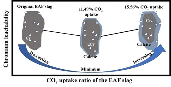
:EAF stainless steel slag (EAF slag) is one kind of chromium-bearing metallurgical solid waste, which belongs to alkaline steel slag, and contains a large number of alkaline mineral phases. The carbonation activity of these minerals gives EAF slag the capability to effectively capture CO2. In this paper, EAF slag samples with different carbonation degrees were prepared by the slurry-phase accelerated carbonation route. The mineralogical identification analysis was used to qualitatively and semi-quantitatively determine the types and contents of the carbonatable mineral phases in the EAF slag. The sequential leaching test was used to study the chromium leachabilities in EAF slags with different carbonation degrees. The results showed that the main minerals with carbonation activity in EAF slag were Ca3Mg(SiO4)2 and Ca2SiO4, with mass percentages of 56.9% and 23%, respectively. During the carbonation process, Ca2SiO4 was the main reactant and calcite was the main product. As the degree of carbonation increased, the pH of the EAF slags’ leachate gradually decreased while the redox potential (Eh) gradually increased. At the same time, a large amount of Ca2+ in the EAF slag combined with CO2 to form slightly soluble calcium carbonate, which led to a significant decrease in the conductivity of the leachate. With the gradual increase in carbonation ratio, the leachability of chromium in the EAF slag first decreased and then increased, and reached its lowest value when the CO2 uptake ratio was 11.49%.
1. Introduction
The mainstream production process of modern stainless steel is a two-step smelting process. First, the electric arc (EAF) furnace is used to initially smelt scrap steel and alloy materials, and then the argon–oxygen decarburization (AOD) furnace is used to perform secondary smelting of molten steel to achieve refining goals such as decarburization and composition adjustment. The metallurgical wastes generated in the two-step process of smelting stainless steel are called EAF stainless steel slag (EAF slag) and AOD stainless steel slag (AOD slag) [1,2]. Stainless steel slag is a type of solid waste with a higher content of chromium than other types of steel slag [3]. Due to this feature, the recovery ratio of stainless steel slag is much lower than that of ordinary steel slags [4].
Cold EAF slag generally exists in black lumps, with larger particles, and is similar in shape to ordinary carbon steel slag [5]. CaO and SiO2 are EAF slag’s main components, and the sum of the two generally accounts for more than 70% of its total mass. In addition, it also contains a small amount of MgO, Al2O3, MnO, and Cr2O3 [1,2,6].
Due to the low recycling ratio, a large amount of EAF slag is in a state of long-term natural storage or landfill [3]. During this period, EAF slag will inevitably have long-term contact with H2O, O2, and CO2 in the air, resulting in hydration reaction of silicate phases, the oxidation reaction of the valence metal ions, and carbonation reaction of calcium (magnesium) phases. These three reactions are collectively called aging reactions [7,8,9,10]. After the aging reaction, the mineral phase composition, microstructure and chromium morphology of EAF slag will be changed, thus affecting the leaching characteristics of chromium.
The mechanism of the effect of carbonation on the leaching characteristics of chromium in the EAF slag is still unclear. In previous research, we established a set of sequential leaching experiments to explore the leaching characteristics of Cr in the original EAF slag and found that in the dissolution of the primary phase, Cr2O3 controlled the leachability of chromium [11]. Baciocchi et al. [12] found that carbonation could increase the chromium leachability in the process of studying the carbonation mechanism of stainless steel slag, and pointed out that this was related to the presence of chromium in different valence states after carbonation. The test results of Chen et al. [13] showed that carbonation increased the amount of chromium released from the EAF slag during the leaching process, which was analyzed to be related to the changes in the microstructure of the slag particles before and after the reaction. Costa et al. [14] compared the leachability of chromium in EAF slag and AOD slag after accelerated carbonation and found that carbonation had a greater influence on Cr leachability in AOD slag than EAF slag. However, Kim et al. [15] found that direct wet carbonation can reduce the amount of chromium leached from stainless steel slag. Furthermore, the mineralogical control behavior of chromium leaching in EAF slag may be affected by changes in the mineralogical characteristics caused by carbonation [10]. It can be seen that the type of steel slag, carbonization route, and mineral phase composition may all have an impact on the leaching characteristics of chromium.
Steel slag mineral carbonization is considered to be a new way to utilize steel slag resources while capturing carbon dioxide [16,17]. During the carbonation process, the mineral phase composition, microscopic morphology, and alkalinity of the steel slag will change, which in turn will change the electrochemical characteristics of the steel slag’s leachate and the chromium leachability [10,18]. Studying the law of chromium leachability as a function of carbonation degree and exploring the balance point of CO2 fixation efficiency and chromium leaching toxicity are important prerequisites for the safe application of steel slag to CO2 capture.
In this paper, EAF slag was used as the research object, and carbonated EAF slags with different carbonation ratios were prepared by direct wet accelerated carbonation method under a condition of large liquid–solid ratio named slurry-phase accelerated carbonation [19]. X-ray diffraction (XRD) and Fourier transform infrared spectroscopy (FT-IR) was used to analyze the mineral phase evolution characteristics of EAF slag during the carbonation process. The sequential leaching experiment [11] was used to explore the influence of carbonation on the leaching characteristics of chromium in EAF slag.
2. Experiment
2.1. Raw Materials
The EAF slag was collected from a stainless steel manufacturer. First, a jaw crusher was used to crush the massive EAF slag, and the alloy particles in the slag were removed by magnetic separation. Then, a 200-mesh standard sieve was used to screen out the steel slag powder with a particle size of fewer than 75 μm. Finally, the EAF slag powder was continuously dried in a drying oven at a temperature of 105 °C for 6 h.
The chemical composition of the EAF slag was detected by XRF, and the results were output in the form of oxide, listed in Table 1. The EAF slag contained CaO, SiO2, and MgO whose mass percentage exceeded 10%, and its ternary alkalinity ((CaO + MgO)/SiO2) was 2.14. The minor components with a mass percentage of less than 10% in the EAF slag included Al2O3, Fe2O3, TiO2, and Cr2O3, of which the mass percentage of Cr2O3 was 6.15%, and the chromium concentration in the original EAF slag before leaching was calculated to be 4.21%.
2.2. Mineral Phase Analysis
The measurement of the samples’ mineral phases was conducted by XRD coupled with FT-IR. An X-ray diffractometer (D/Max-RB) with 40 kV and 100 mA Cu- Kα radiation at a scan rate of 0.03° (2θ) every 6 s was used to obtain XRD diffraction data of samples from 10° to 90°. The MDI Jade 9 analysis software coupled with the ICDD PDF 2009 database was used to analyze the XRD data to conduct qualitative and semi-quantitative analysis of the mineral phase. A Fourier Infrared Spectrometer (EQ UINOX55) was used to collect the spectral information of the sample in the range of 400–4000 cm−1 with an accuracy of 0.5 cm−1.
2.3. Slurry-Phase Carbonation
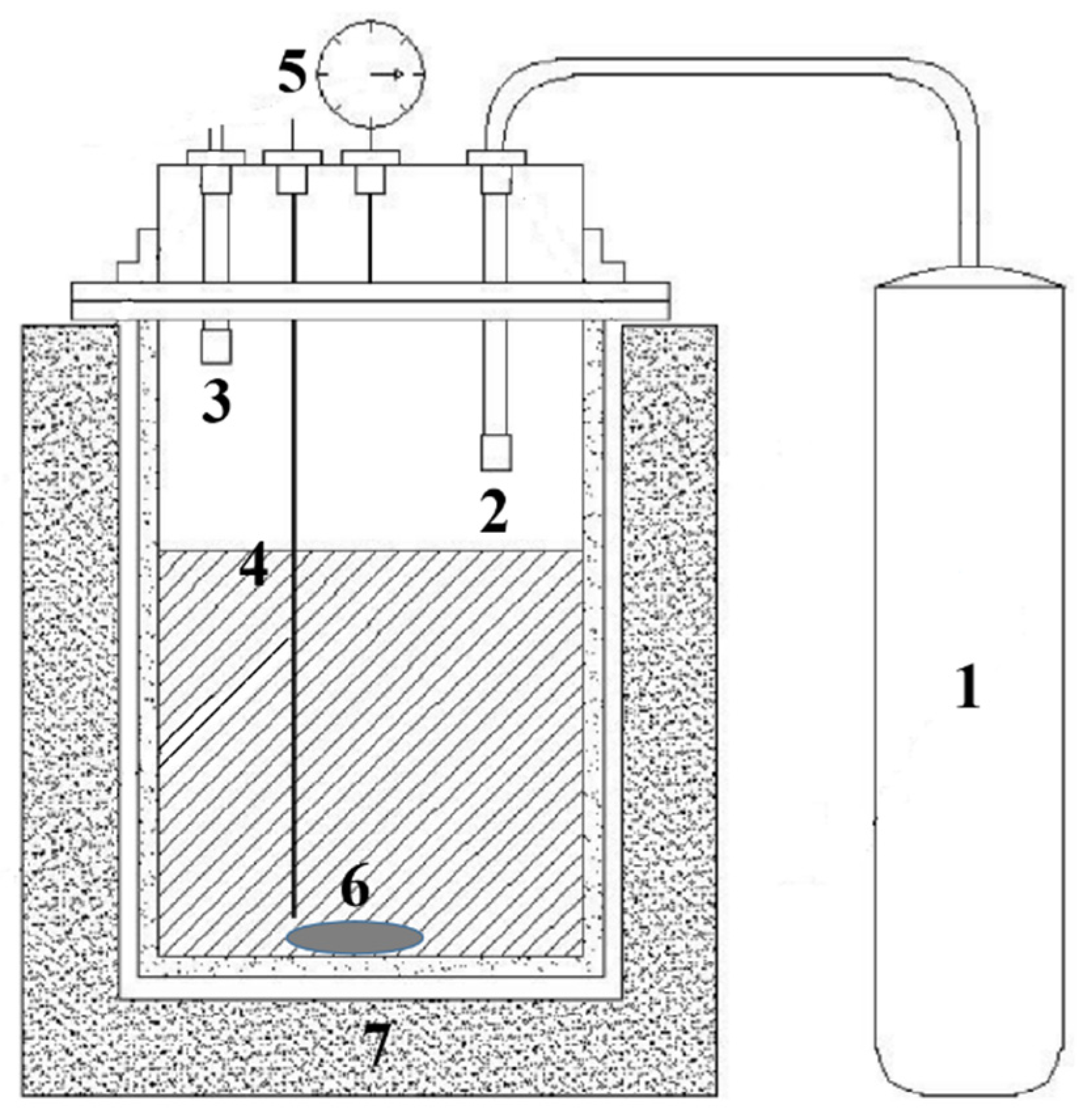
Slurry-phase carbonation was carried out in a high-pressure reactor (Figure 1), which was equipped with a temperature control device, a magnetic stirring device, and a pressure adjustment device. The carbonation parameters were set to T = 90 °C, L/S = 7 L/kg, =8 bar. EAF slag samples with different carbonation degrees were prepared by changing the reaction time. The CO2 uptake ratios of EAF slag was calculated by Equation (1) [20]:
where denotes the CO2 uptake ratios of EAF slag, denotes the mass of CO2 stored in the EAF slag after carbonation, and denotes the mass of EAF slag participating in the carbonation reaction.
was determined by thermogravimetric analysis (TG-DTG), using Setsys Evo type thermogravimetric analyzer to collect 30 mg () carbonate EAF slag under N2 atmosphere at a rate of about 0.33 °C/s at room temperature to 900 °C in the process of the characteristics of gravity (TG) curves. The weight loss temperature range of CaCO3 in the carbonated EAF slag can be analyzed after the DTG curve was obtained by the first-order derivation of the TG curve.
2.4. Sequential Leaching
To study the effect of carbonation on the leaching characteristics of chromium in EAF slag, a 20-day sequential leaching test was designed according to the European Standard EN12457-2 [21] and conducted on EAF slag samples with different CO2 uptake ratios.
Ten grams of EAF slag sample was weighed and placed into a 250 mL conical flask, with 100 mL deionized water added into the same flask to make the liquid to solid ratio (L/S) equal to 10 mL/g. A lid was used to seal the flask to prevent the intrusion of oxygen and carbon dioxide. Then, the sealed flask was placed in a THZ-82A type oscillator and inducing rotation of the conical flask at 60 r/min. Every 24 h an 80 mL supernatant was aspirated for electrochemical and chromium concentration tests. To keep the L/S ratio at the same level in each sampling cycle, 80 mL of deionized water was supplemented accordingly every day.
After filtering, the leachate’s electrochemical characteristics containing pH, redox potential (Eh), and electrical conductivity were examined. In addition, the chromium concentration of the leachate was tested by inductively coupled plasma-optical emission spectrometry (ICP-OES) with a detection limit of 0.004 mg/L. All of the tests were performed in duplicate.
3. Results and Discussion
3.1. Mineral Composition of the Original EAF Slag
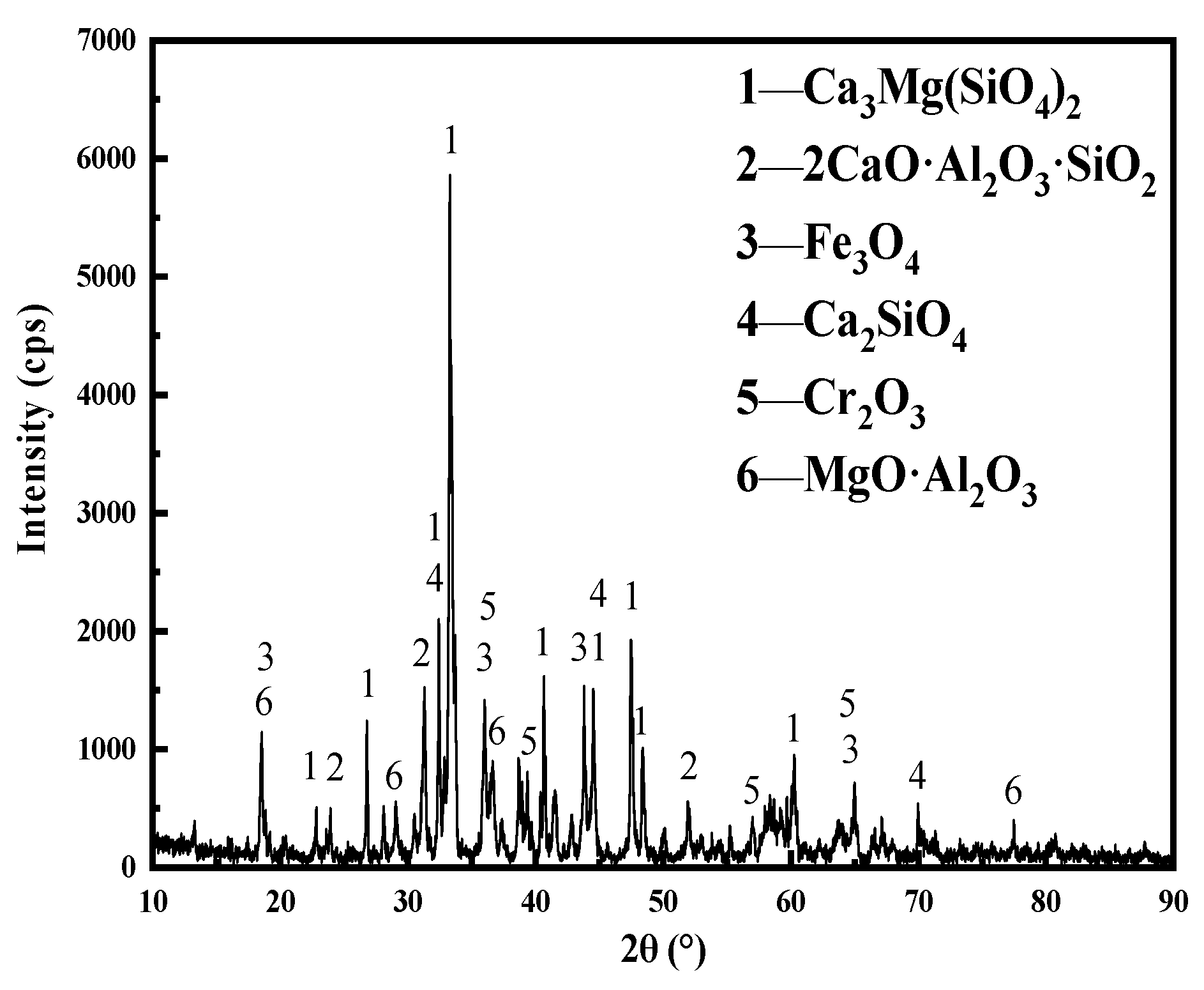
Figure 2 shows the XRD diffraction pattern of the EAF raw slag. The mineral composition of the EAF raw slag mainly includes Ca3Mg(SiO4)2, Ca2SiO4, 2CaO·Al2O3·SiO2, Fe3O4, MgO·Al2O3, and Cr2O3. The “adiabatic method” was used to quantitatively analyze the ore phase composition of the EAF slag [22]. The results showed that the mineral phase with the highest content in EAF slag was Ca3Mg(SiO4)2 with a mass percentage of 56.9%, followed by Ca2SiO4 with a content of 23.0%, and other mineral phases with a mass percentage of less than 10%, belonging to trace mineral phases.
3.2. Carbonation Thermodynamic Analysis
Based on mineral phase analysis, it can be determined that the phases bearing Ca/Mg in the EAF slag were Ca3Mg(SiO4)2, Ca2SiO4, 2CaO·Al2O3·SiO2, and MgO·Al2O3. The phases with carbonation activity under the normal condition were Ca3Mg(SiO4)2 and Ca2SiO4. The standard Gibbs free energy of the carbonation reactions of Ca3Mg(SiO4)2 and Ca2SiO4 was calculated using FactSage 7.2 thermodynamic software and the results were listed in Table 2.
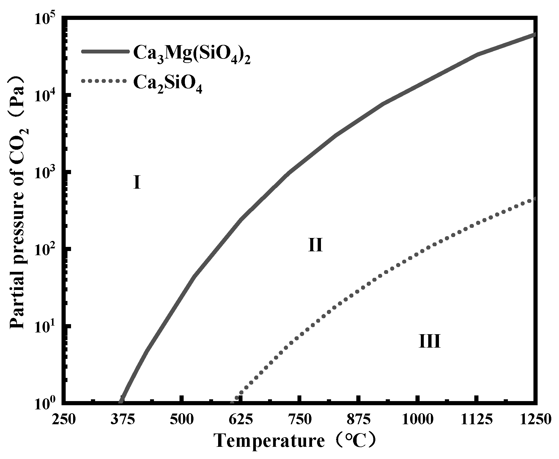
According to the Van’t Hoff equation , the temperature-pressure balance curve (T-P line) of mineral carbonation reaction can be established [10,23], as shown in Figure 3. The two T-P lines corresponding to Ca3Mg(SiO4)2 and Ca2SiO4 divided the entire condition interval into three areas, and the upper region of each T-P line was the range of thermodynamic conditions for carbonation of the mineral phase, that was, in area I, that both Ca3Mg(SiO4)2 and Ca2SiO4 can be carbonated; in area II, Ca2SiO4 can be carbonated but Ca3Mg(SiO4)2 can not be carbonated; in area III, neither of them can be carbonated. The carbonation activity of Ca2SiO4 in EAF slag was higher than that of Ca3Mg(SiO4)2, and the carbonation reaction of the two was exothermic and reduced the gas phase. Therefore, lower temperature and higher partial pressure of CO2 were beneficial to EAF slag carbonation [23].
3.3. Carbonation Products of EAF Slag
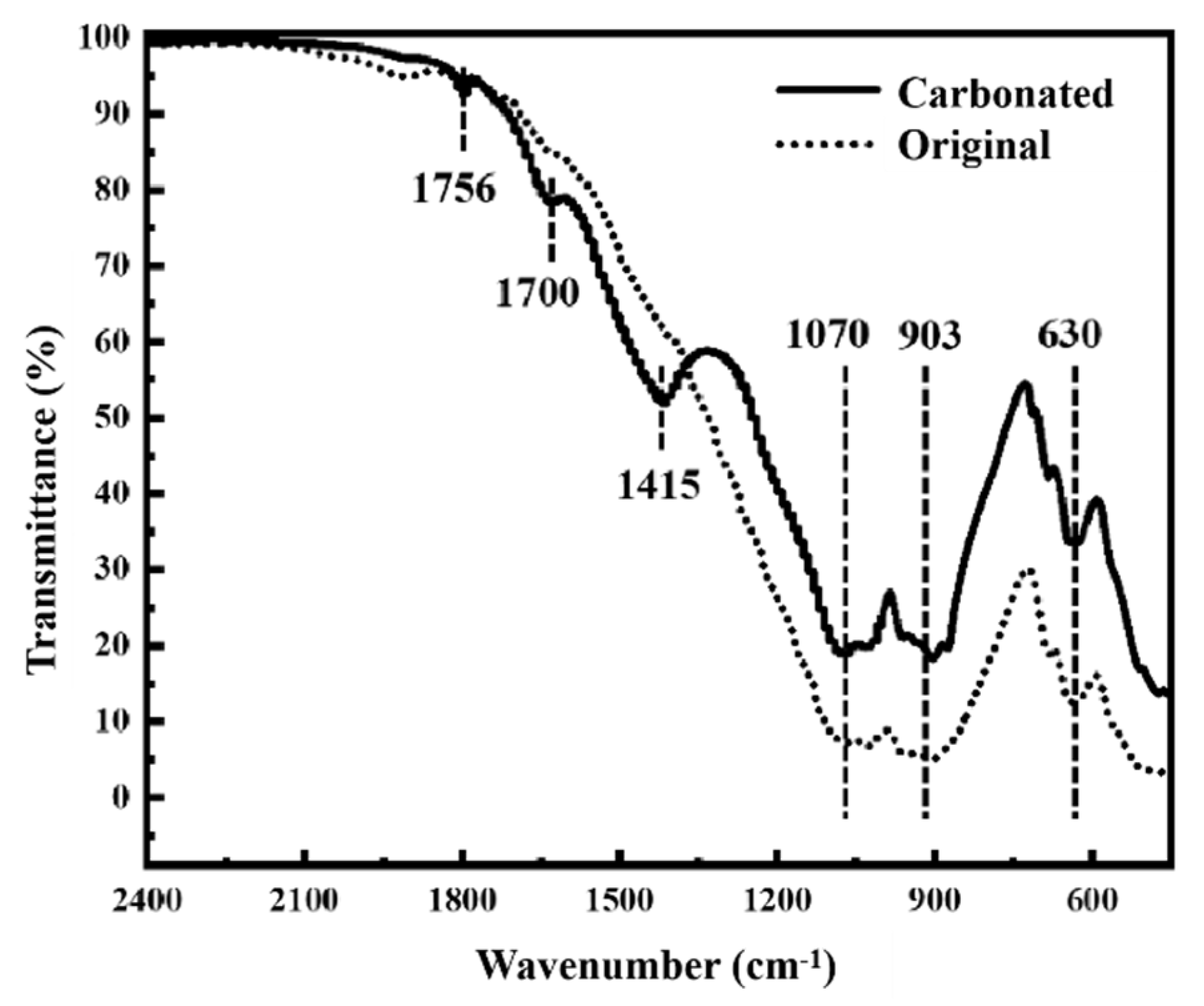
Figure 4 shows the FT-IR curves of the EAF raw slag and carbonated EAF slag. There were three obvious characteristic peaks in the FT-IR curve of the original EAF slag. The characteristic peak at 1070 cm−1 was due to the asymmetric stretching vibration of Si-O-Si, and the characteristic peak at 903 cm−1 was due to the generation of an O-Si-O asymmetric stretching vibration, and the characteristic peak at 630 cm−1 was due to the symmetric stretching vibration absorption of Si-O-Si [24], corresponding to the silicate phase in the EAF slag and the carbonation reaction to form silica gel. In the FT-IR curve of the carbonated EAF slag, in addition to the three characteristic peaks of silicate phase in the FT-IR curve of EAF slag, a typical vibration peak of calcite-type carbonate of 1756 cm−1 (C=O bond), 1700 cm−1 (C=O bond), and 1415 cm−1 (C=O bond) [10]. It can be concluded that the carbonation products of EAF slag were mainly calcite and silica gel. Consistent with the above-mentioned T-P balance curve analysis results, the combination of before and after increases the accuracy of the research results.
3.4. TG-DTG Analysis
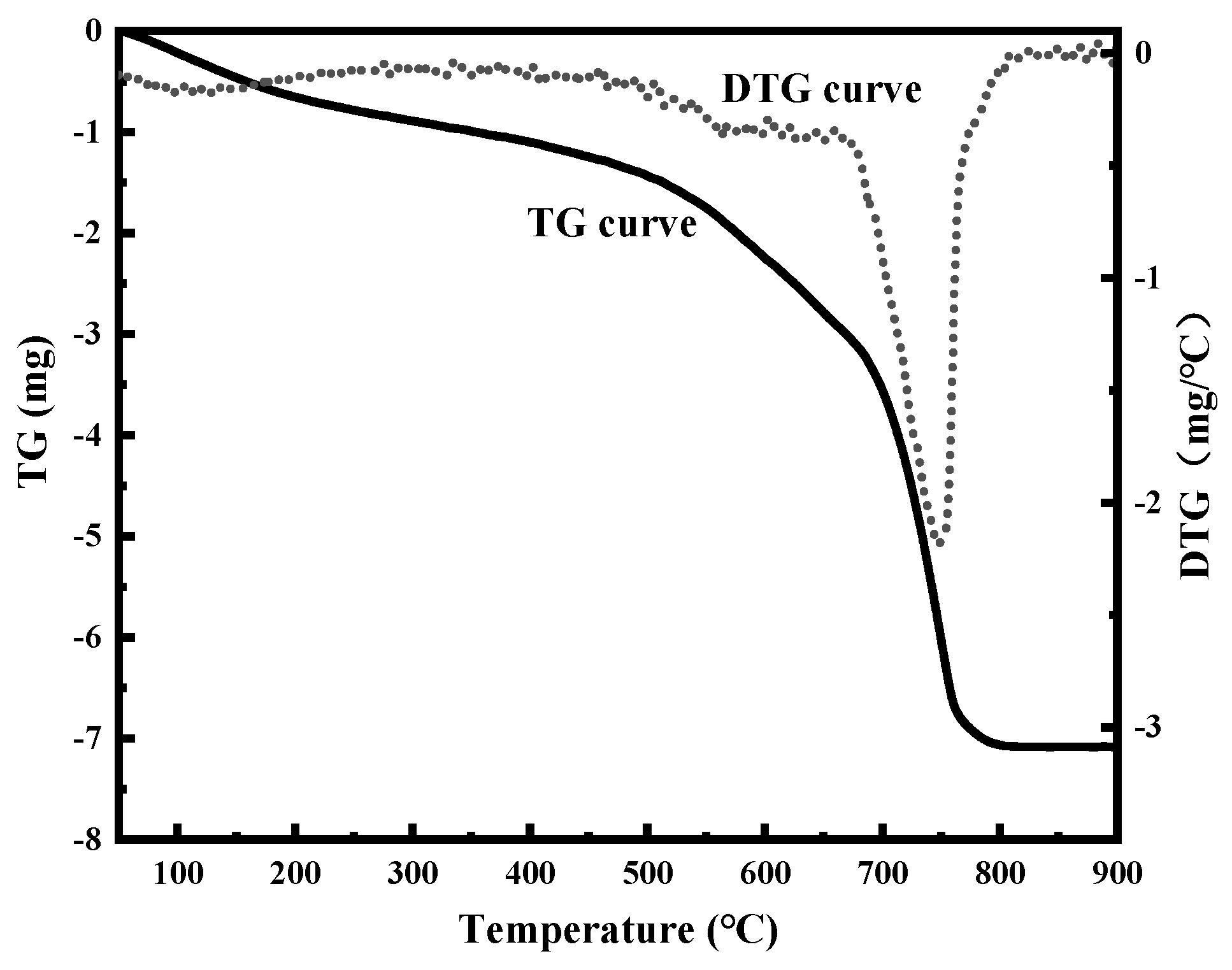
Figure 5 shows the TG-DTG curve of the carbonated EAF slag. It can be seen from the DTG curve that there were two weight loss stages in the carbonated EAF slag during the process of increasing from room temperature to 900 °C. The first stage was the evaporation of combined water and interlayer water at 100–200 °C, and the second stage was the decomposition of Carbonation product-calcite at 500–900 °C. Therefore, in Equation (1) can be calculated by the Equation (2)
Among them,, and finally the calculation Equation (3) for the carbon fixation rate can be obtained. According to Equation (3), calculation of the carbon fixation rate of the carbonated EAF slag with different carbonation times, and the carbonated EAF slag and the original EAF slag with carbon sequestration rates of 9.35, 11.49, 13.37 and 15.56% were selected as continuous leaching objects.
3.5. Effect of Carbonation on Leaching Characteristics of EAF Slag
The electrochemical characteristics of the leachate mainly include pH value, redox potential, and conductivity. Continuous monitoring of the electrochemical characteristics of the leachate was helpful for the in-depth analysis of the influence mechanism of leaching atmosphere on chromium leaching in the original EAF slag and carbonated EAF slag.
3.5.1. Effect of Carbonation on the Leachate’s pH
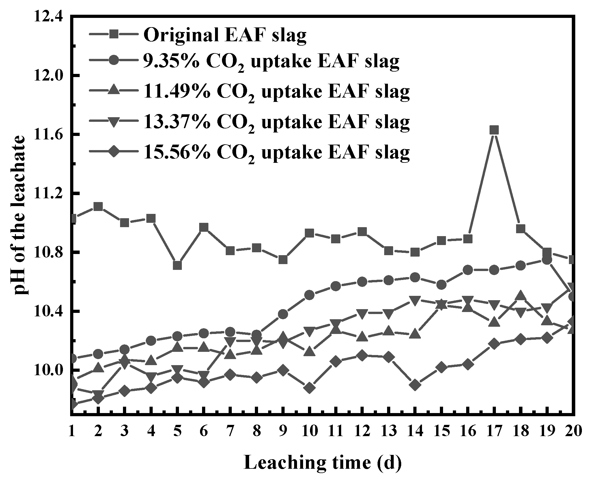
Figure 6 shows the change rule of pH values of EAF slag leachates with leaching time at different CO2 uptake ratios. The pH value of the leaching solution of the original EAF slag was higher than 10.60 during the entire leaching cycle, showing strong alkalinity. This was mainly due to the EAF slag containing a small amount of free alkali metal oxides (f-CaO and f-MgO) and soluble alkaline mineral phases (Ca3Mg(SiO4)2 and Ca2SiO4). After these components came into contact with water, they underwent a hydration reaction and released a large amount of OH−1, which made the leachate appear strongly alkaline.
As the carbonation depth degree of the EAF slag increased, the pH value of the leachate decreased gradually. When the CO2 uptake ratio reached 15.56%, the pH value of the leach solution decreased to about 10. This was because during the carbonation process of EAF slag, Ca and Mg in some basic components such as CaSiO3, f-CaO and f-MgO reacted with CO2 to form insoluble carbonates such as CaCO3 and MgCO3, which led to the gradual reduction of soluble basic components in the carbonation slag, thus reducing the pH value of leaching solution.
As the leaching time was prolonged, the pH value of the original EAF slag leachate decreased gradually, while the pH value of the carbonated EAF slag leaching solution increased gradually. For the original EAF slag, at the initial stage of leaching, the soluble alkaline components in the slag were fully exposed to the leaching solution, which was also known as the rapid hydrolysis of the primary phase, resulting in a sharp increase in pH value. With the prolongation of leaching time, the secondary phase precipitate gradually formed on the surface of slag particles, which hindered the contact between the leaching solution and the alkaline mineral phase. As a result, the pH of the leachate of the original EAF slag decreased gradually in the middle and late stages of leaching. For carbonated EAF slag, the carbonation products attached to the surface of the slag particles can prevent the leachate from contacting the alkaline minerals that had not been carbonated [19]. Therefore, in the early stage of leaching, the pH value of the carbonated EAF slag leachate had a lower starting point, and with the extension of the leaching time, the uncarbonated alkaline mineral phase gradually came into contact with the leachate to undergo hydration reaction, resulting in the pH value of the leachate increasing in the later stage of leaching.
3.5.2. Effect of Carbonation on the Leachate’s Redox Potential (Eh)
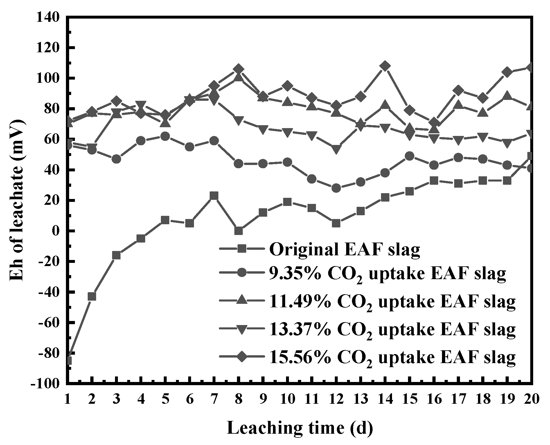
Figure 7 shows the change rule of Eh values of EAF slag leachates with leaching time at different CO2 uptake ratios. During the entire leaching cycle, the Eh of the leachate of the original EAF slag gradually increased from −90 mV to 50 mV, and the leachate went through a process of transition from early reductive to late oxidizing.
With the increase in carbonation depth, the Eh of the leachate gradually increased. With an uptake ratio of 15.56% CO2, the EAF slag leachate’s Eh fluctuated around 90 mV with the leaching time. The leachates of carbonated EAF slags were positive during the entire leaching cycle and did not undergo the process of changing from reduction to oxidization.
The effect of carbonation on leachate’s Eh was mainly related to pH. When the dissolved oxygen in the leachate was in equilibrium with the oxygen in the atmosphere, the oxidation-reduction potential can be calculated by the Equation (4) [25]:
Among them, was the redox potential, was the temperature constant, was the dissolved oxygen concentration, was the gas constant, was the absolute temperature, and was the Faraday constant.
The Eh value was negatively correlated with the pH value and positively correlated with the dissolved oxygen value. The sequential leaching system was in a closed state, so the dissolved oxygen in leachate was nearly unchanged. Therefore, pH became the only factor affecting the redox potential in this experiment.
Combining with the previous analysis, it could be concluded that carbonation reduced the alkalinity of EAF slag, and finally caused the Eh of the leachate to increase.
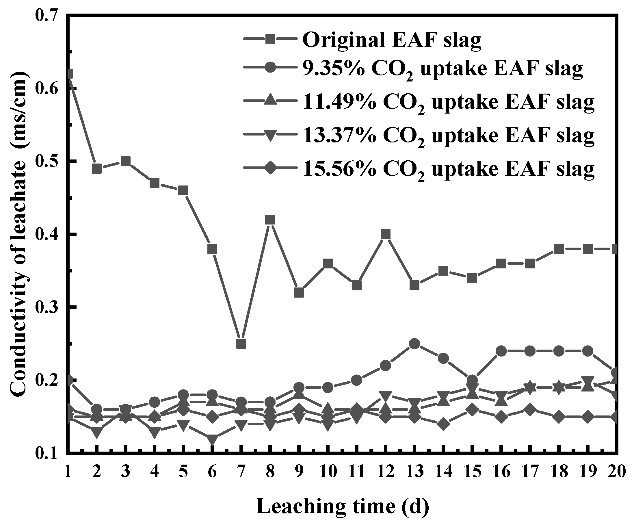
3.5.3. Effect of Carbonation on the Leachate’s Conductivity
Figure 8 shows the change rule of conductivity values of EAF slag leachates with leaching time at different CO2 uptake ratios. The conductivity of the original EAF slag’s leachate decreased gradually from 0.62 mS/cm at the initial stage with the leaching time and finally stabilized at 0.35 mS/cm.
Compared with the original EAF slag, the conductivity of the carbonated EAF slags’ leachate was lower. The stable value of the conductivity of the 15.56% CO2 uptake EAF slag’s leachate was only 0.15 mS/cm. After carbonation, the Ca2+ and Mg2+ plasmas in the EAF slag that could be released into the leachate through mineral hydrolysis reacted with CO2 to form a carbonate phase that was slightly soluble in water under normal conditions [10], significantly reducing the conductivity of the carbonated EAF slag’s leachate.
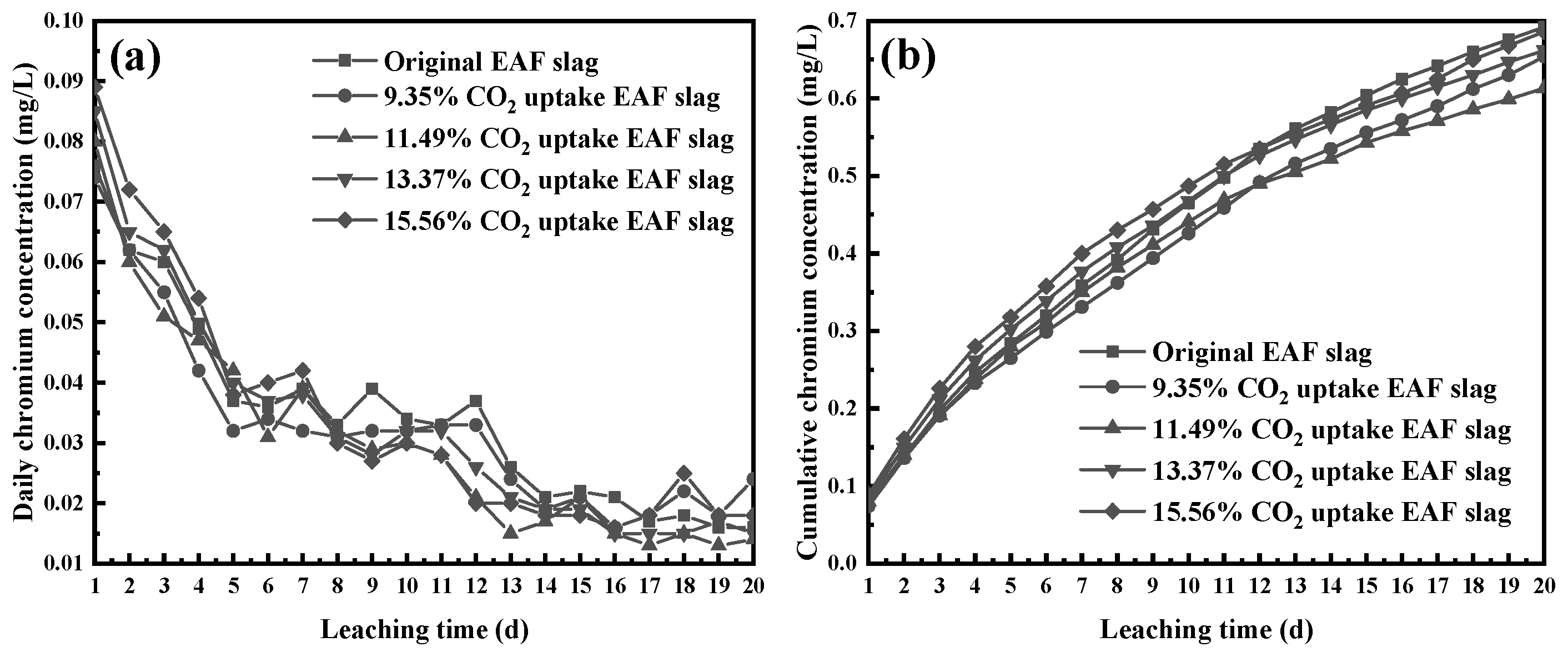
3.5.4. Effect of Carbonation on Chromium Leachability in EAF Slag
Figure 9a shows the evolution of daily chromium concentration in EAF slag’s leachate with different CO2 uptake ratios. In the first and middle stages of leaching, the daily chromium concentration in the leachates of the original EAF slag and carbonated EAF slags gradually decreased, and the daily chromium concentration became stable after 14 days of leaching. In the entire 20-day leaching cycle, the daily chromium concentration of the 15.56% CO2 uptake ratio EAF slag’s leachate was continuously higher than that of the original EAF slag and lower CO2 uptake ratio EAF slags, which showed that deeper carbonation could play a certain role in promoting the leachability of chromium in the EAF slag. Most of the chromium in EAF slag was stably enriched in spinel and Fe-Cr alloy, and a small part was wrapped in silicate in the form of oxide. The main participants in the carbonation of EAF slag were Ca-bearing silicates, and these phases were consumed by carbonation, which made the chromium oxides wrapped in them easier to contact the leaching solution and dissolve into the leaching solution. The effect of carbonation on the electrochemical characteristics of the leachate was not enough to drive the dissolution of spinel and Fe-Cr alloy, so the consumption of carbonation of silicate phase plays a leading role in the daily increase in chromium concentration in the leaching solution. In the late stage of leaching, the impact of carbonation on the daily chromium concentration of the leachate was reduced. At this time, the chromium concentration was controlled by the dissolution balance between the chromium-bearing primary phase and the secondary phase in the solution.
Figure 9b shows the evolution of cumulative chromium concentration in EAF slag’s leachate with different CO2 uptake ratios. After 20 consecutive days of leaching, the cumulative chromium concentration can reflect the effect of carbonation on the leachability of chromium in the EAF slag. As the degree of carbonation increased, the chromium leachability of the EAF slag first decreased and then increased. The EAF slag with a CO2 uptake ratio of 11.49% had the weakest chromium leachability, and the final chromium leachability of the EAF slag with a CO2 uptake ratio of 15.56% was close to that of the original EAF slag. In the EAF slag with a lower degree of carbonation, the carbonation products would adhere to the surface of the slag particles, reducing the chance of chromium coming into contact with the leachate, and playing a role of physical storage. However, when the degree of carbonation was higher, the corrosion depth of carbonation on the slag particles would increase, and the carbonation products would seriously damage the slag particles or completely separate from the slag particles, and gradually lost the physical sequestration of chromium, leading to an increase in chromium leachability.
4. Conclusions
In this study, the carbonation mechanism of EAF slag and subsequent changes in leaching characteristics were investigated. Some conclusions have been found, as follows:
1. The EAF slag were Ca3Mg(SiO4)2 and Ca2SiO4, both of which had carbonation activity under normal temperature and pressure. The carbonation activity of Ca2SiO4 in EAF slag was higher than that of Ca3Mg(SiO4)2, and the carbonation reaction of the two was exothermic and reduced the gas phase. Lower temperature and higher partial pressure of CO2 were beneficial to EAF slag carbonation.
2. As the carbonation degree of the EAF slag increased, the pH of the leachate gradually decreased, while the Eh of the leachate increased, and the leachate of carbonated EAF slag didn’t undergo a process of transformation from the reduction characteristic to the oxidation characteristic during the continuous leaching process.
3. During the carbonation process, the soluble ions in the EAF slag combined with CO2 to form slightly soluble carbonate, which led to a large reduction in the total number of ions in the carbonated EAF slag’s leachate, resulting in a decrease in the conductivity of the leachate.
4. As the carbonation degree of the EAF slag increased, the chromium leachability in the EAF slag decreased first and then increased. After 20-day sequential leaching, the chromium cumulative leaching amount of the carbonated EAF slag with 15.56% CO2 uptake ratio was almost equal to that of the original EAF slag.
Author Contributions
Conceptualization, J.-G.L. and Y.-J.W.; methodology, Y.-J.W.; software, S.-H.L. and S.Q.; validation, Y.-J.W., J.-G.L. and Y.-N.Z.; formal analysis, Y.-J.W.; investigation, Y.-J.W. and Y.-N.Z.; resources, Y.-N.Z. and J.-G.L.; data curation, M.-J.T. and Y.-J.W.; writing—original draft preparation, Y.-J.W. and M.-J.T.; writing—review and editing, J.-G.L. and Y.-N.Z.; visualization, S.Q. and Y.-J.W.; supervision, J.-G.L.; project administration, J.-G.L.; funding acquisition, Y.-N.Z. All authors have read and agreed to the published version of the manuscript.
Funding
This research was funded by the National Natural Science Foundation of China (No. 51704119, 51574108) and the Key Research and Development Project of Tangshan (No. 19140205F).
Data Availability Statement
Not applicable.
Acknowledgments
We wish to express our gratitude to the members of our research team, Bao Liu, Xi Zhang, Yi-Tong Wang, Tao Li, Zhi-Yuan Gao, and Wei Wang.
Conflicts of Interest
The authors declare no conflict of interest. The funders had no role in the design of the study; in the collection, analyses, or interpretation of data; in the writing of the manuscript, or in the decision to publish the results.
References
- Wei, D.X.; Xu, A.J.; He, D.F.; Tian, N.Y.; Yang, Q. Beneficial Reuse of EAF Slag and Its Leaching Behavior of Cr. Iron Steel 2012, 47, 92–96. [Google Scholar]
- Wang, Z.J.; Yang, J.; Pan, D.A.; Liu, B.; Tian, J.J.; Zhang, S.G. Present state of stainless steel slag resources disposal technique. J. Iron Steel Res. 2015, 27, 1–6. [Google Scholar]
- Lv, Y.; Yang, L.B.; Lin, L.; Liang, Q. Leaching characteristics and affecting factors of total chromium and chromium VI in chromium-containing special steel slag. Iron Steel 2019, 54, 103–108. [Google Scholar]
- Rosales, J.; Cabrera, M.; Agrela, F. Effect of stainless steel slag waste as a replacement for cement in mortars. Mechanical and statistical study. Constr. Build. Mater. 2017, 142, 444–458. [Google Scholar] [CrossRef]
- Lan, S.W.; Zhang, Z.W.; Hong, A.Y.; Wang, X.; Xu, H. Research Status of Comprehensive Utilization of Stainless Steel Slag. Metall. Eng. 2019, 6, 34–39. [Google Scholar] [CrossRef]
- Zhao, L.; Li, J.G.; Zeng, Y.N.; Wang, Y.J. Effect of Dissolved Oxygen on Static Leaching of EAF Slag. Ind. Saf. Environ. Prot. 2019, 45, 93–97. [Google Scholar]
- Zhao, J.H.; Wang, D.M.; Yan, P.Y. Design and experimental study of a ternary blended cement containing high volume steel slag and blast-furnace slag based on Fuller distribution model. Constr. Build. Mater. 2017, 140, 248–256. [Google Scholar] [CrossRef]
- Lee, J.Y.; Choi, J.S.; Yuan, T.F.; Yoon, Y.S.; Mitchell, D. Comparing Properties of Concrete Containing Electric Arc Furnace Slag and Granulated Blast Furnace Slag. Materials 2019, 12, 1371. [Google Scholar] [CrossRef] [Green Version]
- Pillay, K.; Blottnitz, H.V.; Petersen, J. Ageing of chromium(III)-bearing slag and its relation to the atmospheric oxidation of solid chromium(III)-oxide in the presence of calcium oxide. Chemosphere 2003, 52, 1771–1779. [Google Scholar] [CrossRef]
- Wang, Y.-J.; Zeng, Y.-N.; Li, J.-G.; Zhang, Y.-Z.; Zhang, Y.-J.; Zhao, Q.-Z. Carbonation of argon oxygen decarburization stainless steel slag and its effect on chromium leachability. J. Clean. Prod. 2020, 256, 120377. [Google Scholar] [CrossRef]
- Wang, Y.-J.; Zeng, Y.-N.; Li, J.-G.; Gao, Z.-Y. Leaching characteristics and mineralogical control of chromium in electric-arc-furnace stainless-steel slag. Mater. Tehnol. 2021, 55, 127–133. [Google Scholar] [CrossRef]
- Baciocchi, R.; Costa, G.; Bartolomeo, E.D.; Polettini, A.; Pomi, R. Carbonation of Stainless Steel Slag as a Process for CO2 Storage and Slag Valorization. Waste Biomass Valorization 2010, 1, 467–477. [Google Scholar] [CrossRef]
- Chen, Q.; Johnson, D.C.; Zhu, L.; Yuan, M.; Hills, C.D. Accelerated carbonation and leaching behavior of the slag from iron and steel making industry. J. Univ. Sci. Technol. Beijing Miner. Metall. Mater. 2007, 14, 297–301. [Google Scholar] [CrossRef]
- Baciocchi, R.; Costa, G.; Polettini, A.; Pomi, R. Effects of thin-film accelerated carbonation on steel slag leaching. J. Hazard. Mater. 2015, 286, 369–378. [Google Scholar] [CrossRef]
- Kim, E.; Spooren, J.; Broos, K.; Nielsen, P.; Horckmans, L.; Vrancken, K.C.; Quaghebeur, M. New method for selective Cr recovery from stainless steel slag by NaOCl assisted alkaline leaching and consecutive BaCrO4 precipitation. Chem. Eng. J. 2016, 295, 542–551. [Google Scholar] [CrossRef]
- Li, L.; Ling, T.-C.; Pan, S.-Y. Environmental benefit assessment of steel slag utilization and carbonation: A systematic review. Sci. Total Environ. 2022, 806, 150280. [Google Scholar] [CrossRef]
- Luo, Y.; He, D. Research status and future challenge for CO2 sequestration by mineral carbonation strategy using iron and steel slag. Environ. Sci. Pollut. Res. 2021, 28, 49383–49409. [Google Scholar] [CrossRef]
- Costa, G.; Polettini, A.; Pomi, R.; Stramazzo, A. Leaching modelling of slurry-phase carbonated steel slag. J. Hazard. Mater. 2016, 302, 415–425. [Google Scholar] [CrossRef]
- Wang, C.Y.; Bao, W.J.; Xu, D.H.; Guo, Z.C.; Li, H.Q.; Pan, K. Reaction characteristics of steelmaking slag carbonation in dilute alkali medium. Iron Steel 2016, 51, 87–93. [Google Scholar]
- Santos, R.M.; Bouwel, J.V.; Vandevelde, E.; Mertens, G.; Elsen, J.; Gerven, T.V. Accelerated mineral carbonation of stainless steel slags for CO2 storage and waste valorization: Effect of process parameters on geochemical properties. Int. J. Greenh. Gas Control 2013, 17, 32–45. [Google Scholar] [CrossRef] [Green Version]
- BS EN 12457-2:2002. Characterisation of Waste-Leaching-Compliance Test for Leaching of Granular Waste Materials and Sludges; Technical Specification; British Standards Institution: London, UK, 2002. [Google Scholar]
- Wang, Z.M.; Li, J.G.; Liu, B.; Zeng, Y.N.; Gao, Z.Y. Study on mineralogical phase composition and quantitative analysis of argon oxygen decarburization slag. Metall. Anal. 2017, 37, 15–20. [Google Scholar]
- Tang, H.Y.; Sun, S.H.; Meng, W.J.; Liu, H.; Wang, S.; Li, J.S. Progress in carbon dioxide sequestration by mineral carbonation. China Metall. 2013, 23, 2–8. [Google Scholar]
- Zhao, W.Y.; Zhang, Q.J.; Peng, C.Q. FTIR spectra for molecular structure of wollastonite. J. Chin. Ceram. Soc. 2006, 34, 1137–1139. [Google Scholar]
- Xu, H.C.; Xu, X.J.; Wang, K.; Huang, J.G. An analysis of factors affecting the oxidation reduction potential in drinking water. J. Univ. Sci. Technol. Suzhou (Eng. Technol.) 2007, 20, 63–66. [Google Scholar]
Figure 1.
Schematic diagram of carbonation reactor, 1—CO2 cylinder; 2—Air inlet; 3—Air outlet; 4—Thermometer; 5—Barometer; 6—Magnetic rotor; 7—Heating equipment.
Figure 1.
Schematic diagram of carbonation reactor, 1—CO2 cylinder; 2—Air inlet; 3—Air outlet; 4—Thermometer; 5—Barometer; 6—Magnetic rotor; 7—Heating equipment.

Figure 2.
XRD pattern of the original EAF slag.

Figure 3.
T-P equilibrium diagram of carbonatable phases in the EAF slag (log scale).

Figure 4.
FT-IR spectra of the original EAF slag and the carbonated EAF slag.

Figure 5.
TG and DTG curves of the carbonated EAF slag.

Figure 6.
Evolution of leachates’ pH as a function of leaching time.

Figure 7.
Evolution of leachates’ Eh as a function of leaching time.

Figure 8.
Evolution of leachates’ conductivity as a function of leaching time.

Figure 9.
Evolution of daily chromium concentration (a) and cumulative chromium concentration (b) as a function of leaching time.
Figure 9.
Evolution of daily chromium concentration (a) and cumulative chromium concentration (b) as a function of leaching time.


Table 1.
Chemical composition of the EAF slag (wt.%).
| Oxides | CaO | SiO2 | MgO | Al2O3 | Fe2O3 | TiO2 | Cr2O3 | Other |
|---|---|---|---|---|---|---|---|---|
| Content | 38.64 | 24.01 | 12.63 | 9.55 | 4.32 | 1.61 | 6.15 | 3.09 |
Table 2.
Carbonation reaction equations of carbonatable phases in the EAF slag.
| Mineral Phase | Carbonation Reaction Equation | Standard Gibbs Free Energy (ΔGθ) | Entropy (Q) |
|---|---|---|---|
| Ca3Mg(SiO4)2 | Ca3MgSi2O8 + 4CO2 = 3CaCO3 + MgCO3 + 2SiO2 | -412,023 J/mol | −4 |
| Ca2SiO4 | Ca2SiO4 + 2CO2 = 2CaCO3 + SiO2 | -211,878 J/mol | −2 |
Publisher’s Note: MDPI stays neutral with regard to jurisdictional claims in published maps and institutional affiliations. |
© 2021 by the authors. Licensee MDPI, Basel, Switzerland. This article is an open access article distributed under the terms and conditions of the Creative Commons Attribution (CC BY) license (https://creativecommons.org/licenses/by/4.0/).
Share and Cite
MDPI and ACS Style
Wang, Y.-J.; Tao, M.-J.; Li, J.-G.; Zeng, Y.-N.; Qin, S.; Liu, S.-H. Carbonation of EAF Stainless Steel Slag and Its Effect on Chromium Leaching Characteristics. Crystals 2021, 11, 1498. https://0-doi-org.brum.beds.ac.uk/10.3390/cryst11121498
AMA Style
Wang Y-J, Tao M-J, Li J-G, Zeng Y-N, Qin S, Liu S-H. Carbonation of EAF Stainless Steel Slag and Its Effect on Chromium Leaching Characteristics. Crystals. 2021; 11(12):1498. https://0-doi-org.brum.beds.ac.uk/10.3390/cryst11121498
Chicago/Turabian StyleWang, Ya-Jun, Meng-Jie Tao, Jun-Guo Li, Ya-Nan Zeng, Song Qin, and Shao-Hua Liu. 2021. "Carbonation of EAF Stainless Steel Slag and Its Effect on Chromium Leaching Characteristics" Crystals 11, no. 12: 1498. https://0-doi-org.brum.beds.ac.uk/10.3390/cryst11121498
Note that from the first issue of 2016, this journal uses article numbers instead of page numbers. See further details here.