
New Insight on Liquid Steel Microalloying by Pulse-Step Method in Two-Strand Slab Tundish by Numerical Simulations


Department of Metallurgy and Metals Technology, Faculty of Production Engineering and Materials Technology, Czestochowa University of Technology, 19 Armii Krajowej Ave, 42-200 Czestochowa, Poland
Crystals 2021, 11(4), 448; https://0-doi-org.brum.beds.ac.uk/10.3390/cryst11040448
Submission received: 2 April 2021
/
Revised: 16 April 2021
/
Accepted: 17 April 2021
/
Published: 20 April 2021
(This article belongs to the Special Issue Liquid Steel Alloying Process)
Abstract
:Developing a technology for introducing alloy addition to liquid steel during the course of continuous casting process seems to be an interesting approach to enhancing the steelmaking process, especially as the effective introduction of micro-additives or non-metallic inclusion modifiers to the liquid steel is the key to the production of the highest-quality steel. This paper presents the results of investigation describing the process of liquid steel chemical homogenisation in the two-strand slab tundish. The alloy was fed to liquid steel by pulse-step method. Five tundish equipment variants with different flow control devices and alloy addition feeding positions were considered. The paper includes fields of liquid steel flow, alloy concentration vs. time curves, dimensionless mixing time, minimum time values and alloy concentration deviations at tundish outlets. The results pointed much more effectively with liquid steel mixing nickel than aluminium. For aluminium obtaining a 95% chemical homogenisation level requires three-fold more time. Moreover, it is definitely beneficial for chemical homogenisation to initiate the alloying process simultaneously in two sites. This procedure generates, among others, the least alloy deviation of concentration at tundish outlets.
1. Introduction
The continuous steel casting (CSC) process is based on the flow of liquid steel between the ladle, the tundish, the mould and the secondary cooling zone. Before the liquid steel begins to solidify, it is poured from the ladle into the tundish, where it stays for a certain time. The primary function of the tundish is to protect the liquid steel against secondary oxidation and to maintain the required temperature of the cast steel grade. In addition, the tundish may support liquid steel refining processes through non-metallic inclusions flotation or Ca treatment [1]. Moreover, the tundish can be used for liquid steel alloying [2,3]. The basic and additional functions can be assisted by modifying the hydrodynamic conditions using flow control devices (FCDs). FCDs are mounted in the internal working volume of the tundish. FCDs contain dams, weirs, dams with holes, gas-permeable barriers, subflux turbulence controllers and electromagnetic stirrers [4,5,6,7,8,9,10,11,12,13]. However, the majority of these devices, like the tundish working space, are made of refractory materials that gradually erode during the casting sequence and from contact with liquid steel or slag. Nonetheless, in the case of tundishes with a capacity over 60 Mg, casting in tundishes without FCDs is recommended [14]. The feed stream flowing into the tundish is an energy carrier that can be successfully used to mix the alloy additions with the liquid steel. The proposed pulse-step method (PSM) allows a 95% level of chemical homogenisation to be obtained in a satisfactory time during the continuous steel casting process [15]. Nevertheless, the tundish as a flow reactor has certain limitations, compared to the ladle furnace used for standard alloying of liquid steel. The main factors limiting the alloying process in the tundish are the permanent drop in the temperature of the liquid steel entering the tundish and the significantly shorter residence time of the liquid steel in the tundish than in the ladle furnace. Therefore, the process of feeding the alloy addition to liquid steel can only be used to correct the chemical composition of the cast grade or modify non-metallic inclusions. Selection of the site to feed the alloy addition to the tundish filled with liquid steel is extremely important, due to the significant differentiation of the hydrodynamics of steel flow in its individual working zones, especially when tundish working volume is modified by FCDs [15,16,17,18]. The previous works were performed for one strand wedge-shaped tundish; therefore, it was essential to check the usefulness of the PSM method during steel casting using a multi-strand tundish. This paper presents the results of computer simulations of feeding the slight alloy addition to liquid steel by pulse-step method (microalloying) during casting of slabs through two-strand, trough-shaped tundish.
2. Tundish Description
The nominal capacity of the considered tundish is 75 Mg. The two-strand tundish is equipped with a stopper rod system to regulate the flow of liquid steel to the moulds. The liquid steel entering the tundish is protected by a ceramic ladle shroud with an inner diameter of 0.11 m. Combinations of considered tundish equipment and alloy addition feeding positions give 11 computer simulation cases (Table 1). Five variants of the tundish equipment were tested in computer simulations. In the first variant, the tundish was not equipped with flow control devices. Figure 1 shows the sites where the alloy addition was introduced to the liquid steel during the CSC process. In alloy addition feeding position No. 1, the additive was fed in one place. However, in the remaining simulation cases, the alloy addition was fed in parallel at two selected locations located parallel or transversely to the longitudinal axis of the tundish. The alloy addition feed sites are mainly located in the tundish pouring zone where the feed stream most intensely affects the liquid steel. The AAFP No. 4 was located outside the tundish pouring zone, halfway between the tundish pouring zone and the tundish outlet.
In the second tundish equipment variant (TEV), the tundish was fitted with two 1 m high weirs and two 0.26 m high dams. Both types of flow control devices were mounted in the immediate vicinity of the tundish pouring zone. The task of the weirs is to stabilize the free surface of liquid steel, while the dams stimulate liquid steel rising movement in the direction of the free surface. In the third to fifth tundish designs, flow reactor was equipped additionally with a combination of two weirs and two dams. Weirs and dams were installed near the stopper rod system. The height of both FCDs were 0.52 m. In the fifth variant, FCDs from the tundish pouring zone were removed.
3. Research Methodology
Numerical simulation of the liquid steel flow and alloy addition behaviour in turbulent motion conditions was done using the Ansys-Fluent® (version 12.1, Ansys Inc., Canonsburg, PA, USA) computer program. To build the virtual tundish model with an appropriate computational grid, Gambit software was used. Tet/hybrid elements were used to generate the computational grid. To assure independence of computational mesh on results, high and even number of elements on the particular edges of tundish model were matched. The virtual tundish models built, on average, 1,300,000 elements generated. This computational mesh insured proper numerical results. The Navier–Stokes equation was solved for liquid steel and alloy. All numerical simulations were done by employing a double-precision solver (3ddp) using discretisation of the second order for momentum, turbulent motion, species, energy and transient formulation. Numerical simulations were performed for the sequence of casting 1.5 m × 0.22 m slabs at a speed of 1.4 m/min and with the initial steel temperature of 1833 K. The level of chemical homogenisation was determined using the following relationship:
where Cf is the final effective concentration of alloy at tundish outlets (wt%), CPSM is the dimensionless concentration of alloy for PSM, Ct is the temporary concentration of alloy (wt%), and C0 is the initial concentration of alloy (wt%).
In numerical simulations, the alloy addition in the form of nickel or aluminium was fed. The purpose of alloying was to adjust the chemical composition of the liquid steel by 0.055 wt%. The liquid steel enters the tundish at the velocity of 1.61 m/s. Turbulence intensity of liquid steel inflow to tundish was assumed with a turbulence kinetic energy of 0.025921 m2/s2 and dissipation rate of 0.075878 m2/s3. Properties of liquid steel, nickel and aluminium were presented in the Table 2.
The numerical simulations include diffusivity of nickel or aluminium in the liquid steel. Melting process and shell rising were not considered during numerical simulations. This simplification was verified by continuous slab casting tundish experiments and confirmed quite good consistency between computing and industrial results [19]. All boundary and initial model conditions were described in the author’s previous works [15,16,17,18,19,20]. Based on the concentration vs. time curves, the dimensionless mixing time (DMT) was calculated. The DMT is defined as the period after which the minimum required liquid steel chemical homogenisation level is maintained, which should amount to at least 95%. The time interval was expressed by dimensionless time, defined by the ratio of the actual time to the average time. The average time for the tundish under examination was 700 s. The previous numerical, physical and industrials studies have confirmed the usefulness of the used numerical model for simulating the macro chemical homogenisation process during steel flow through the tundish [19,20].
4. Results and Discussion
4.1. Hydrodynamic Conditions
The first stage of investigations covered tundish equipment variants No. 1 and No. 2. On the basis of computer simulations, steel flow fields were developed that reflect the hydrodynamic conditions for the two considered tundish equipment. Figure 2a–d show the path lines and flow fields in a tundish without FCDs (bare tundish). The global hydrodynamic view shows some recirculation zones progressed from pouring zone to tundish outlets. In the central part of the bare tundish, the feed stream after impact against the bottom of the tundish is separated into two streams flowing towards the tundish outlets. More or less in the middle of the distance between the feed zone and the outlet zones, the flow direction of the feed stream is modified by back streams. As a result, two liquid steel circulation zones are created at the bottom of the tundish. In the central part of the tundish, the directions of liquid steel movement have a falling character. However, at both side walls parallel to the longitudinal axis of the tundish, there are four steel circulation zones. The feed streams flow towards the outlets along the bottom and then float towards the free surface to reach the stopper rod zones. Next, the liquid steel streams fall and partially feed the tundish outlets flowed into the moulds. The liquid steel streams remaining in the tundish turn back at the bottom towards the feed zone. In the feed zone, liquid steel circulation zones are created, resulting from the separation and return of some feed streams rising at a distance of about 2 m from the feed zone. In the tundish without FCDs, the steel movement is usually symmetrical in relation to the tundish pouring zone. The use of dams and weirs in the tundish feed zone significantly modified the steel flow (Figure 2e–h). The full sight of fluid flow behaviour shows more ordered hydrodynamic structure in the zones between FCDs system and both tundish outlets. The mounted FCDs caused an intensive mixing zone of liquid steel in which the feed streams separate into many smaller recirculation flows between the weirs. In addition, the liquid steel movement in individual zones of the tundish was unified. After leaving the feed zone, the dams stimulate rising movement of the liquid steel streams towards the free surface. Upon reaching the stopper rod zones and side walls transverse to the longitudinal axis of the tundish, some of the streams enter the outlets. The remaining liquid steel streams along the bottom of the tundish return to the dams. As a result, portions of the liquid steel circulate between the feed zone and the stopper rod zones.
In the tundish without FCDs, the average velocity of liquid steel in the tundish working volume was 0.0515 m/s. Meanwhile, FCDs application resulted in a reduction of the average velocity by 0.0137 m/s, due to braking the momentum of the feed stream by the system of dams and weirs. Thus, the mounted FCDs definitely affected not only the directions of liquid steel flow but also the flow velocity between the tundish pouring zone and the outlet zones, which should also affect the kinetics of the alloy–liquid steel mixing process.
4.2. Chemical Homogenisation Conditions
In the author’s previous work, the effect of alloy density on mixing process was presented [18]. Therefore, two extremely different density alloys were adopted to present investigation. A change in the concentration of the alloy addition in the liquid steel at the tundish outlets as a function of time in the form of mixing curves enabled qualitative analysis of the dynamics of the microalloying process during the CSC process. In the first stage of the study, four sites of feeding the alloy addition in the form of nickel in a tundish without FCDs were tested. Figure 3 shows the distribution of nickel in the liquid steel flowed into the mould for two selected characteristic cases. In the computer simulation with the additive feeding site marked with number 2 and tundish without FCDs, a different distribution of nickel concentration at the tundish outlets is visible. At the same time, the nickel concentration reaches 95% level of chemical homogenisation faster at outlet number 1. In the second case from Figure 3, the 95% level of chemical homogenisation was obtained faster. Both cases indicate strong asymmetry of the mixing process resulting from initiation of the alloying process in the regions marked with numbers 2 and 3. The dimensionless mixing time necessary to obtain the required 95% level of chemical homogenization was calculated from the concentration vs. time curves. For the simulation case, where the additive was only fed at one site, the required chemical homogenisation level during heat casting was much smaller at outlet number 1. In the case of initiating the alloying process in parallel at two sites (AAFP No. 2), a discrepancy in the mixing time for individual outlets was obtained, equal to 0.3 DMT. However, in the third simulation case a significant reduction in the mixing time was obtained for both outlets number. The best mixing conditions regarding uniformity were obtained for the simulation case of feeding the alloy addition outside the tundish pouring zone, where the mixing times for both outlets were about 0.8 DMT.
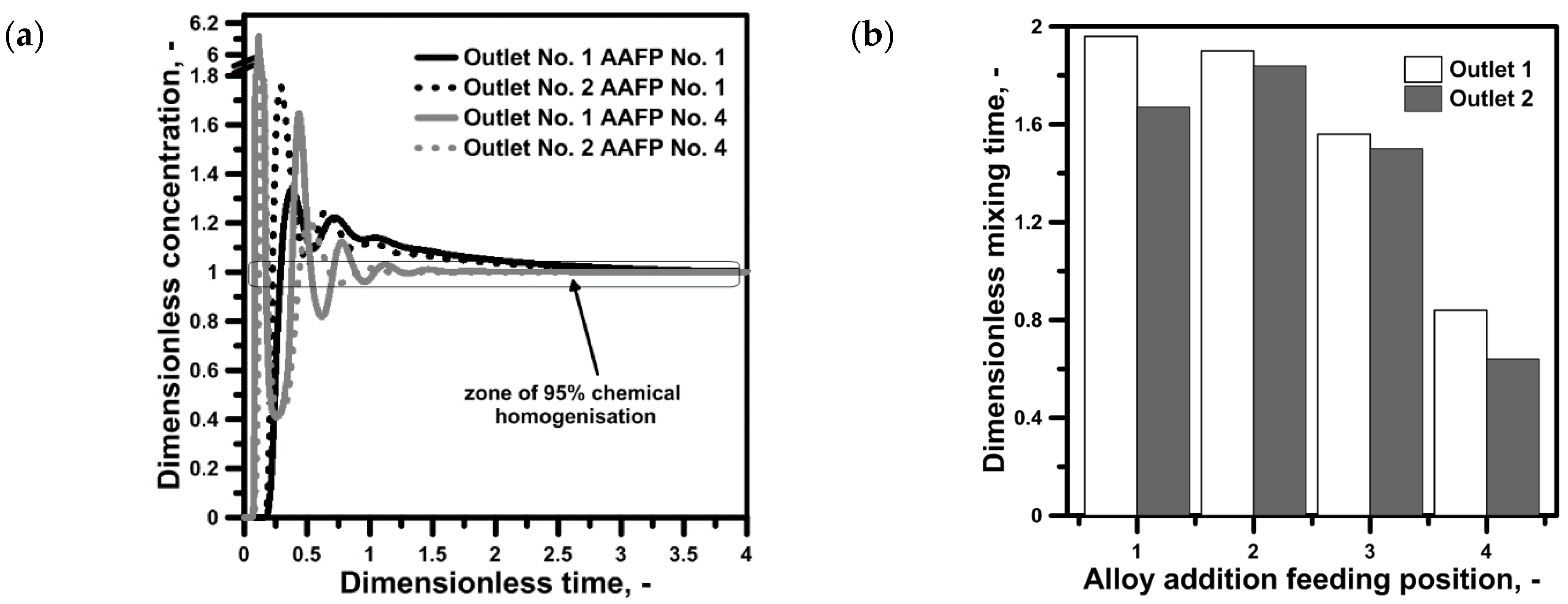
In the following stage of the research, the influence of the tundish equipment variant No. 2 on the chemical homogenisation process initiating the alloying of liquid steel with the nickel metal in the four analysed areas of the tundish was verified. Figure 4a shows the mixing process in a tundish with FCDs for two AAFPs. The AAFP No. 1 shows more hard conditions to achieve the required 95% chemical homogenization level at both outlets of the tundish. On the other hand, in the case of alloying steel by AAFP No. 4, the distribution of the mixing curves indicates that the planned correction of the chemical composition of liquid steel is faster than in the tundish without FCDs. Mounting FCDs in the tundish modified the hydrodynamic conditions of the liquid steel flow conducive to active recirculation visible in the form of a decreasing amplitude of the mixing curve. In addition, the use of FCDs resulted in significantly higher peak values recorded at the tundish outlet, which indicates a greater concentration of the alloy addition in the feed streams of the moulds. At the same time, the employed FCDs homogenised the steel flow in individual tundish zones in relation to the longitudinal axis, which reduced the asymmetry of the mixing process for AAFPs No. 1–3. However, the mixing time for both outlets exceeded 1.5 DMT. Mounting FCDs did not allow a satisfactory result of chemical homogenisation to be obtained in the case of the alloying process initiation site marked with numbers 1–3. A mixing time below 1 DMT, fairly aligned for both outlets, was obtained by introducing nickel outside the feed zone of the tundish equipped with the proposed FCDs.
In addition, in order to assess the impact of the used tundish equipment, the minimum time required to obtain the 0.005% concentration of the alloy addition at the individual tundish outlets was estimated. This time is the period that elapses between introducing the alloy addition to the liquid steel and its appearance at the outlets in an amount significant for the chemical composition of the cast slabs. This time should be long enough for the alloy addition to reach the liquid state by melting and dissolving in liquid steel before it enters the mould along with the liquid steel stream. The minimum time for nickel and the tundish without FCDs and the alloying process initiation sites marked with numbers 1–3 was 0.098–0.129 DMT and 0.152–0.191 DMT for the tundishes without and with FCDs, respectively. On the other hand, when initiation of the alloying process was transferred to the area between the tundish pouring zone and the tundish outlets, the minimum time increased to 0.136–0.139 DMT in the tundish without FCDs and decreased to 0.077–0.09 DMT in the tundish with FCDs. The obtained minimum times associated with the chemical homogenisation processes reflect the hydrodynamic conditions that arose in the analysed tundish operating areas. The obtained minimum periods were characterized by a similar value for both outlets, as well as the second addition in the form of aluminium. The shortest minimum time was 1 min, which is why the selection of the linear dimensions of the additive is important in the process of alloying liquid steel in the tundish.
In the next stage of the study for the considered variants of the tundish equipment and alloy addition feeding positions, it was checked how the aluminium would behave in the volume of liquid steel. Figure 5a shows the concentration vs. time curves for tundish equipment variants No. 1 and 2 and alloy addition feeding positions outside the tundish pouring zone. As in the case of nickel, the behaviour of aluminium in liquid steel is also correlated with the tundish equipment. In the tundish with FCDs, the characteristic wave of the mixing curve with gradually decreasing amplitude is visible. In contrast, the mixing of aluminium with liquid steel is definitely weaker than in the case of nickel, as evidenced by the definitely higher concentration of aluminium in the streams flowing through the outlets in the initial period of casting. The majority of the obtained mixing times for aluminium exceeded the value of 2.5 DMT, which, when, casting in 4 DT is 3/5 of the time of casting, which must pass to obtain the required chemical homogenisation level. The obtained mixing times for aluminium at the 3 DMT level concerned only one of the two outlets, while for the second, 95% chemical homogenization level was 2.75 DMT in the bare tundish. Moreover, for aluminium, the shortest mixing time was obtained for AAFP No. 4 and the tundish with FCDs. However, in relation to nickel steel microalloying, introducing the aluminium and obtaining a 95% chemical homogenisation level requires three-fold more time.
4.3. New Solutions for Tundish Equipment
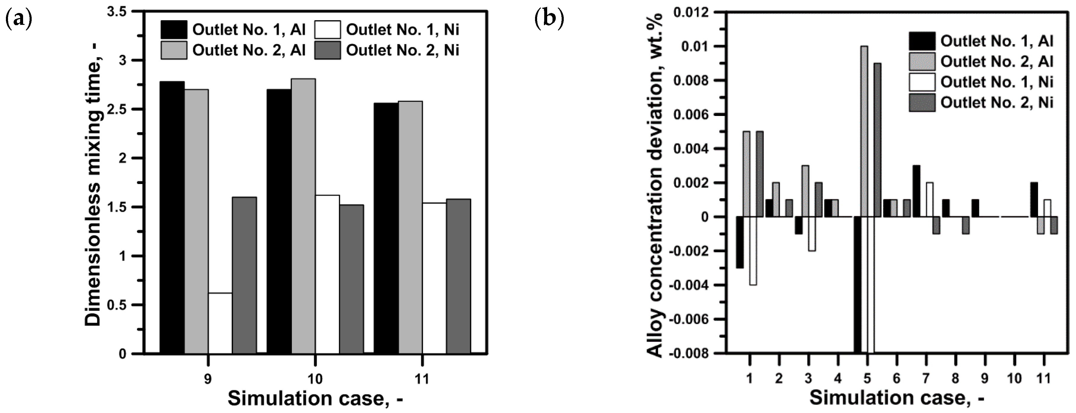
The aim of the next investigations was to check possibility of decreasing dimensionless mixing time in the considered tundish by using other combinations of FCDs. New designs of tundish were performed to evoke some additional recirculation in the liquid steel volume. The average velocity of liquid steel in the liquid steel volume was 0.0504 m/s in the tundish equipment variant No. 5, which was a very similar to value for the bare tundish. In contrast, for TEV Nos. 3–4, liquid steel velocity amounted to 0.0370 m/s. Therefore, the fifth considered tundish equipment variant changed liquid steel flow but did not decrease average velocity. Figure 6 shows concentration vs. time curves for the three following tundish equipment. Concentration vs. time curves for nickel and aluminium characterise symptomatic peaks, especially in the tundish with additional FCDs in the zones near outlets. Quite different concentration vs. time curves for both alloys were obtained for the tundish with FCDs mounted only in the stopper rod system zones. Referring to proposed new tundish design solutions, TEV No. 5 assured the least DMT on the level of value 2.5 for Al and 1.5 for Ni, with very small concentration imbalance at both outlets (Figure 7). A very important problem for liquid steel microalloying is actual alloy concentration obtained at the outlets. Figure 7b presents real alloy concentration deviation in relation to the purpose of microalloying and adjusting the chemical composition of the liquid steel by 0.055 wt%. The highest deviations of alloy concentrations were obtained for AAFP No. 1, while AAFP No. 4 allowed the elimination of deviations or gain value 0.001 %wt. Therefore, for choosing the best tundish equipment and AAFP, not only should DMT be considered but alloy deviations at both outlets, as well.
5. Conclusions
Based on the computer simulations carried out, it has been found that:
- The proposed pulse-step method of microalloying liquid steel during the CSC process can be successfully applied in the considered two-strand tundish during slabs casting.
- For the analysed tundish, it is definitely beneficial for chemical homogenisation to initiate the alloying process simultaneously in two sites.
- The chemical homogenisation process can be intensified by appropriate selection of the FCDs. The shortest mixing time for nickel with liquid steel was obtained below 0.8 DMT in the tundish with dams/weirs system in the pouring zone.
- Liquid steel alloying by aluminium requires a much longer mixing time. In the tundish with FCDs, the shortest mixing time for aluminium was close 2.5 DMT, when the dams/weirs system was localized only in the stopper rod zones.
- The AAFP No. 1 generated the most alloy deviation of concentration at tundish outlets referred to assumed aim of liquid steel microalloying.
Funding
This scientific work has been financed from the resources of Polish National Science Centre in the years 2017–2019 as Research Project No. 2016/23/B/ST8/01135 and from the resources of the Polish Ministry of Science and Higher Education in the year 2020–2021 as Statutory Research (Research project No. BS/PB-200-301/2020 and No. BS/PB-200-301/2021).
Data Availability Statement
The data presented in this study are available within the article.
Conflicts of Interest
The author declares no conflict of interest.
References
- Sahai, Y. Tundish technology for casting clean steel: A review. Metal. Mater. Trans. B 2016, 47, 2095–2106. [Google Scholar] [CrossRef]
- Stolte, G. Secondary Metallurgy; Verlag Stahleisen GmbH: Düsseldorf, Germany, 2002; ISBN 3-514-00648-2. [Google Scholar]
- Kimura, H.; Mori, M.; Miura, R.; Sugawara, K.; Uehara, A.; Tanaka, H.; Shirai, T. Innovative technologies in continuous casting tundish. Nippon Steel Rep. 1994, 22–28. [Google Scholar]
- Chatterjee, S.; Li, D.; Chattopadhyay, K. Modeling of Liquid Steel/Slag/Argon Gas Multiphase Flow During Tundish Open Eye Formation in a Two-Strand Tundish. Metal. Mater. Trans. B 2018, 49, 756–766. [Google Scholar] [CrossRef]
- Mazumdar, D.; Yamanoglu, G.; Guthrie, R.I. Hydrodynamic performance of steelmaking tundish systems: A comparative study of three different tundish designs. Steel Res. Int. 1997, 68, 293–300. [Google Scholar] [CrossRef]
- Yue, Q.; Zhang, C.B.; Wang, X.Z. Mathematical simulation for effects of flow control devices in two-strand slab tundish. Metalurgija 2017, 56, 126–130. [Google Scholar]
- Bul’ko, B.; Molnár, M.; Demeter, P.; Baricová, D.; Pribulová, A.; Futáš, P. Study of the Influence of Intermix Conditions on Steel Cleanliness. Metals 2018, 8, 852. [Google Scholar] [CrossRef] [Green Version]
- Zhong, L.; Li, L.; Wang, B.; Jiang, M.; Zhu, L.; Zhang, L.; Chen, R. Water Modelling Experiments of Argon Bubbling Curtain in a Slab Continuous Casting Tundish. Steel Res. Int. 2006, 77, 103–106. [Google Scholar] [CrossRef]
- Braun, A.; Warzecha, M.; Pfeifer, H. Numerical and Physical Modeling of Steel Flow in a Two-Strand Tundish for Different Casting Conditions. Metal. Mater. Trans. B 2010, 41, 549–559. [Google Scholar] [CrossRef]
- Tripathi, A. Mathematical modelling of flow control in a tundish using electro-magnetic forces. Appl. Math. Model 2011, 35, 5075–5090. [Google Scholar] [CrossRef]
- Smirnov, A.N.; Efimova, V.G.; Kravchenko, A.V. Flotation of Nonmetallic Inclusions during Argon Injection into the Tundish of a Continuous Casting Machine. Part 1. Steel Transl. 2013, 43, 673–677. [Google Scholar] [CrossRef]
- Chen, D.; Xie, X.; Long, M.; Zhang, M.; Zhang, L.; Liao, Q. Hydraulics and Mathematics Simulation on the Weir and Gas Curtain in Tundish of Ultrathick Slab Continuous Casting. Metall. Mater. Trans. B 2014, 45, 392–398. [Google Scholar] [CrossRef]
- Odenthal, H.J.; Bölling, R.; Holzhauser, J.F.; Wahlers, F.J. Mechanism of fluid flow in a continuous casting tundish with different turbo-stoppers. Steel Res. Int. 2001, 72, 466–476. [Google Scholar] [CrossRef]
- Sahai, Y.; Emi, T. Tundish Technology for Clean Steel Production; World Scientific: Singapore, 2008; ISBN 10-981-270-621-6. [Google Scholar]
- Cwudziński, A. Pulse-step method for liquid steel alloying in one strand slab tundish. Ironmak. Steelmak. 2015, 42, 373–381. [Google Scholar] [CrossRef]
- Cwudziński, A. Numerical simulation of the liquid steel alloying process in a one-strand tundish with different addition positions and flow control devices. Metall. Res. Technol. 2015, 112, 305. [Google Scholar] [CrossRef]
- Cwudziński, A. Optimization of Pulse-Step Method for Liquid Steel Alloying in One Strand Slab Tundish. Mater. Sci. Forum 2018, 941, 58–63. [Google Scholar] [CrossRef]
- Cwudziński, A.; Jowsa, J. Influence of selected alloy additions on time mixing for pulse-step method of liquid steel alloying in the tundish. Metall. Ital. 2019, 111, 20–27. [Google Scholar]
- Cwudziński, A. Numerical, Physical and Industrial Studies of Liquid Steel Chemical Homogenisation in One Strand Tundish with Subflux Turbulence Controller. Steel Res. Int. 2015, 86, 972–983. [Google Scholar] [CrossRef]
- Cwudziński, A.; Gajda, B.; Hutny, A.; Jowsa, J. Mathematical and physical modeling of alloy behavior feeding by pulse-step method to liquid steel in one strand slab tundish. Arch. Metall. Mater. 2018, 63, 2081–2087. [Google Scholar]
Figure 1.
Two-strand slab tundish: (a) alloy addition feeding position, (b) tundish with flow control devices, (c) tundish with additional dams/weirs, (d) tundish with additional weirs, and (e) tundish with dams/weirs only in the zones of stopper rod system.
Figure 1.
Two-strand slab tundish: (a) alloy addition feeding position, (b) tundish with flow control devices, (c) tundish with additional dams/weirs, (d) tundish with additional weirs, and (e) tundish with dams/weirs only in the zones of stopper rod system.

Figure 2.
Liquid steel flow path lines: (a) bare tundish global view, (b) longitudinal front plane in the tundish without FCDs, (c) longitudinal middle plane in the tundish without FCDs, (d) longitudinal back plane in the tundish without FCDs, (e) weirs/dams tundish global view, (f) longitudinal front plane in the tundish with FCDs, (g) longitudinal middle plane in the tundish with FCDs, and (h) longitudinal back plane in the tundish with FCDs.

Figure 3.
Tundish without FCDs: (a) alloy concentration vs. time curves for nickel alloying; (b) dimensionless mixing time.
Figure 3.
Tundish without FCDs: (a) alloy concentration vs. time curves for nickel alloying; (b) dimensionless mixing time.

Figure 4.
Tundish with FCDs: (a) alloy concentration vs. time curves for nickel alloying; (b) dimensionless mixing time.
Figure 4.
Tundish with FCDs: (a) alloy concentration vs. time curves for nickel alloying; (b) dimensionless mixing time.

Figure 5.
Tundish without and with FCDs: (a) alloy concentration vs. time curves for aluminium alloying by AAFP No. 4, (b) dimensionless mixing time.
Figure 5.
Tundish without and with FCDs: (a) alloy concentration vs. time curves for aluminium alloying by AAFP No. 4, (b) dimensionless mixing time.

Figure 6.
Alloy concentration vs. time curves: (a) nickel; (b) aluminium.

Figure 7.
Tundish equipment variant Nos. 3–5: (a) dimensionless mixing time; (b) final alloy concentration deviation.
Figure 7.
Tundish equipment variant Nos. 3–5: (a) dimensionless mixing time; (b) final alloy concentration deviation.


Table 1.
Considered cases of computer simulations.
| Simulation Case No. | Tundish Equipment Variant, TEV | Alloy Addition Feeding Position | |||||||
|---|---|---|---|---|---|---|---|---|---|
| 1 | 2 | 3 | 4 | 5 | 1 | 2 | 3 | 4 | |
| 1 | √ | √ | |||||||
| 2 | √ | √ | |||||||
| 3 | √ | √ | |||||||
| 4 | √ | √ | |||||||
| 5 | √ | √ | |||||||
| 6 | √ | √ | |||||||
| 7 | √ | √ | |||||||
| 8 | √ | √ | |||||||
| 9 | √ | √ | |||||||
| 10 | √ | √ | |||||||
| 11 | √ | √ | |||||||
Table 2.
Properties of fluids. Adapted from ref. [18].
Table 2.
Properties of fluids. Adapted from ref. [18].
| Alloy | Density, kg/m3 | Viscosity, Pa·s | Heat Capacity, J/kg·K | Thermal Conductivity, W/m·K | Diffusivity, m2/s |
|---|---|---|---|---|---|
| Steel | 7010 | 0.007 | 750 | 41 | - |
| Nickel | 7790 | 0.00159 | 556 | 50 | 5.3 × 10⁻⁹ |
| Aluminium | 2100 | 0.00052 | 1180 | 91 | 8.6 × 10⁻⁹ |
Publisher’s Note: MDPI stays neutral with regard to jurisdictional claims in published maps and institutional affiliations. |
© 2021 by the author. Licensee MDPI, Basel, Switzerland. This article is an open access article distributed under the terms and conditions of the Creative Commons Attribution (CC BY) license (https://creativecommons.org/licenses/by/4.0/).
Share and Cite
MDPI and ACS Style
Cwudziński, A. New Insight on Liquid Steel Microalloying by Pulse-Step Method in Two-Strand Slab Tundish by Numerical Simulations. Crystals 2021, 11, 448. https://0-doi-org.brum.beds.ac.uk/10.3390/cryst11040448
AMA Style
Cwudziński A. New Insight on Liquid Steel Microalloying by Pulse-Step Method in Two-Strand Slab Tundish by Numerical Simulations. Crystals. 2021; 11(4):448. https://0-doi-org.brum.beds.ac.uk/10.3390/cryst11040448
Chicago/Turabian StyleCwudziński, Adam. 2021. "New Insight on Liquid Steel Microalloying by Pulse-Step Method in Two-Strand Slab Tundish by Numerical Simulations" Crystals 11, no. 4: 448. https://0-doi-org.brum.beds.ac.uk/10.3390/cryst11040448
Note that from the first issue of 2016, this journal uses article numbers instead of page numbers. See further details here.