
A Nanoscale Photonic Crystal Cavity Optomechanical System for Ultrasensitive Motion Sensing


1
College of Meteorology and Oceanography, National University of Defence Technology, Changsha 410073, China
2
Department of Mechanical Engineering, Faculty of Engineering, National University of Singapore, Singapore 117575, Singapore
*
Author to whom correspondence should be addressed.
Crystals 2021, 11(5), 462; https://0-doi-org.brum.beds.ac.uk/10.3390/cryst11050462
Submission received: 15 March 2021
/
Revised: 11 April 2021
/
Accepted: 12 April 2021
/
Published: 21 April 2021
(This article belongs to the Special Issue Photonic Crystal Lasers)
Abstract
:Optomechanical nanocavities open a new hybrid platform such that the interaction between an optical cavity and mechanical oscillator can be achieved on a nanophotonic scale. Owing to attractive advantages such as ultrasmall mass, high optical quality, small mode volume and flexible mechanics, a pair of coupled photonic crystal nanobeam (PCN) cavities are utilized in this paper to establish an optomechanical nanosystem, thus enabling strong optomechanical coupling effects. In coupled PCN cavities, one nanobeam with a mass meff~3 pg works as an in-plane movable mechanical oscillator at a fundamental frequency of . The other nanobeam couples light to excite optical fundamental supermodes at and 1554.464 nm with a larger than 4 × 10⁴. Because of the optomechanical backaction arising from an optical force, abundant optomechanical phenomena in the unresolved sideband are observed in the movable nanobeam. Moreover, benefiting from the in-plane movement of the flexible nanobeam, we achieved a maximum displacement of the movable nanobeam as 1468 . These characteristics indicate that this optomechanical nanocavity is capable of ultrasensitive motion measurements.
1. Introduction
Cavity optomechanical systems, which integrate mechanical oscillators with optical cavities into micro-/nanoscale photonic devices, have reinforced the interaction between optical modes and mechanical modes to an unprecedented level [1,2]. By carefully designing the quality factor (Q) and tight subwavelength confinement of a nanophotonic cavity, an optical force arising from the strong optomechanical coupling can be excited and modify the behaviors of the nanomechanical oscillator [3]. Therefore, ultrasensitive measurements based on nanophotonic devices can be achieved in optomechanical systems to monitor the physical variation of force [4,5,6], acceleration [7,8,9,10] and displacement [11,12,13,14].
Generally, optomechanical systems established on photonic platforms include Fabry–Perot (F–P) cavities [15], whispering gallery mode (WGM) cavities [16] and photonic crystal (PhC) cavities. Considering the high-quality factors and small mode volumes, as well as good on-chip integrability with photonic integrated circuits (PICs), PhC cavities facilitate the enhancement of optomechanical interaction and have attracted great attention in sensing applications [17,18,19]. Leveraging advanced nanofabrication technologies, photonic crystal nanobeam (PCN) cavities have exceptional advantages due to their ultracompact size and mass, ultrasmall mode volume and high integrability with PICs. More importantly, when a PCN cavity is achieved with a flexible nanomechanical structure, the strong optomechanical coupling in the nanoscale nanobeam has been demonstrated to greatly affect its mechanical stiffness and damping [20]. As a result, these flexible PCN cavities in optomechanical systems are of particular interest for engineering sensing applications of displacement and force. In 2013, researchers from Caltech Painter lab [11,12] experimentally demonstrated squeezed light in zipper PCN cavities for displacement sensing. The in-plane differential mechanical motion driven by optical force modified the slot gap between two nanobeams and hence modulated the optical readouts. Another suspended paddle-like PCN cavity with hundreds of femtograms of mass [6] was demonstrated to be exploited in the measurement of mechanical motion. Under the effect of optical force, nonlinear optomechanics occurred when the optical mode was coupled into the square of mechanical displacement with an excited in-plane optomechanical motion coupling coefficient of 1 THz/. Furthermore, benefiting from its ultrasmall mass and flexible mechanics, PCN cavities are attractive candidates for force sensing. Force sensors based on split PCN cavities were widely studied using a suspended moving nanobeam [4]. Strong optomechanical coupling in the PCN cavity was realized when a torque-induced motion of suspended nanobeam tuned the splitting gap. A torque sensitivity of 1.2 × in ambient conditions was realized in an optomechanical system. These optomechanical nanocavity systems also provided a unique platform for magnetic field sensing with magnetostrictive materials deposited on the surface of a movable nanobeam [21]. Due to its high torque sensitivity, this optomechanical split PCN nanocavity could detect a minimum magnetic field strength of 44–60 μT. In these PCN-cavity-based motion-sensing schemes, most nanobeams in the cavities are doubly anchored on the device layer, thus enabling large mechanical rigidity and greater optical force applied to drive its motion. Consequently, the optomechanical coupling strength is generally smaller than that in the flexible mechanical structure. To obtain a larger optomechanical coupling strength, another coupled PCN cavity with a cut-off point on each side of the nanocantilever [22] was demonstrated to excite cavity optomechanics. However, in addition to the optical-force-induced motion, the large thermal-optical effect also caused the mechanical elastic deformation of the movable cantilever and dominated the optomechanical damping effect. As the large mechanical oscillation of the optomechanical nanocavity reached the nonlinear regime, self- and cross-saturation were observed and hence caused mode competition between two in-plane mechanical modes. This mode competition resulted in the significant amplification of mechanical oscillation and contributed to a bistable optomechanical system. Inspired by these optomechanical effects and sensing characteristics in the coupled PCN cavities, in this paper, an optomechanical nanocavity consisting of two PCNs is proposed with high optomechanical coupling strength and large optical-force-driven displacement. In this coupled PCN cavity, one of the PCNs is cut off to obtain a flexible nanobeam acting as a movable mechanical oscillator; the other fixed nanobeam is contacted with a dimpled fiber taper to excite the optical mode. The interaction between the optical mode and mechanical mode in this coupled PCN cavity gives rise to an optical force to modify the mechanical motion of movable nanobeam. Finally, noise analysis is performed on the optomechanical system to evaluate the sensitivity of displacement.
2. Principles
In an optomechanical system, the strong optomechanical coupling is realized in the interaction between the optical cavity and the motion of the mechanical resonator. In this proposed cavity scheme, the optical force comes from the optomechanical coupling effect and can be related to the gradient of optical cavity energy , where and are the stored photon number and Planck constant, respectively. In these coupled nanobeams, the optomechanical coupling strength is exponentially proportional to the slot gap (s) between the beams with a coupling length . The value of is determined by , approximately equal to the beam width, and the decay factor , equal to half of the slot gap with reference to previous works [23,24]. Considering the effect of , the optomechanical interaction equation to indicate the light amplitude coupled with mechanical displacement is given as
where α and are the classical correspondence of the cavity mode and input field mode, respectively; and refer to the total and external decay rates of the cavity mode; represents laser detuning between the laser and optical cavity; and and are the natural frequency and damping ratio of the mechanical oscillator. This coupled optomechanical equation indicates the optomechanical backaction effect between the mechanical motion and optical force.
An optomechanical PCN cavity not only allows for high-resolution displacement measurements but can also optically modify the behavior of mechanical motion. The optical force results in the detuning-dependent amplification or damping of mechanical motion. Perturbative analysis shows that in the sideband unresolved limit (), the effective mechanical frequency () and damping rate () are given by the following relations [24],
where is the waveguide-loaded optical cavity energy decay rate, and . In the unresolved sideband, Equation (2) implies that the spring of the mechanical oscillator will be softened under the red laser detuning ( < 0) and hardened under the blue laser detuning ( > 0). Furthermore, Equation (3) indicates that extra damping leads to cooling, while antidamping leads to the amplification of mechanical motion.
When it comes to the measurement of mechanical displacement, through the optomechanical coupling between displacement x and cavity resonance ω_cav, the mechanical motion can be transduced to the variation of the light field. In this work, the behavior of the mechanical oscillator is measured and analyzed by an electric signal analyzer (ESA). As detecting the optical transmission allows measuring mechanical displacement, the optical power received by the photodetector is converted to a power spectral density signal as [7],
where = 40,000 V/W and Z = 50 are the transimpedance gain of the Newport 811 photodetector and the resistance of the ESA, and quantifies the optical loss in the fiber taper between the cavity and the detector via ( and are the input power and the optical power reaching the detector). Based on the optomechanical parameters from the experimental results in Section 4 and the relationship between displacement and optical power in Equation (4), the optical displacement sensitivity can be determined as 7.77 nW/pm.
3. PCN Design and Experimental Setup
3.1. Cavity Design and Fabrication
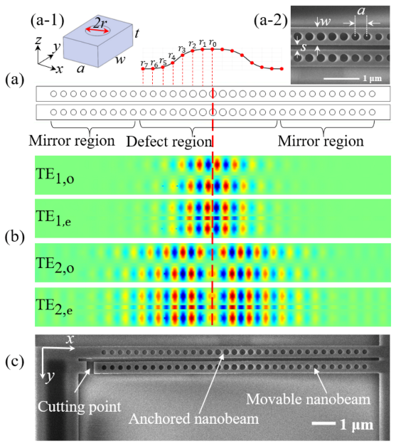
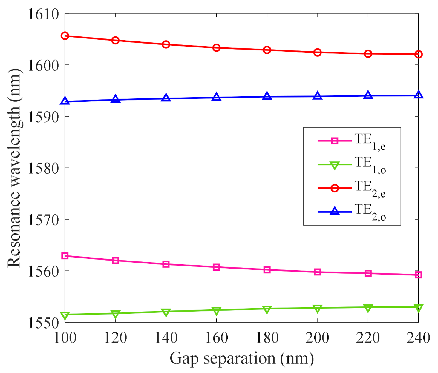
In the optomechanical nanomechanical resonators, a pair of silicon PCNs are coupled to each other. To interpret the device design, a single-PCN structure is introduced using finite-element simulations performed in Lumerical FDTD. As presented in Figure 1a, the single-PCN cavity consists of a center defect region and two side-mirror regions. Regarding the design steps given in Refs. [25,26], the design of the proposed PCN starts with determining the central unit cell, as shown in the inset of Figure 1(a-1,a-2). The unit cell here is determined by several geometric parameters, including silicon thickness t = 220 nm, width w = 560 nm, the radius of the air hole r0 = 128 nm and lattice constant a = 365 nm. According to the relationship between the mirror strength and filling factor given in Ref. [26], the minimum radius of the air hole in the dielectric band edge is solved as r7 = 106 nm. In the defect region, the radii of the remaining 7 air holes on each side are tapered by following a symmetric power function to reduce the optical loss. When two optical modes of the PCN cavity are coupled, based on the well-established temporal coupled-mode theory [27], the photonic bands in the coupled PCN cavity break into pairs of bonded (even) and antibonded (odd) parity supermode bands because of the strong coupling between two PCN cavities. Figure 1b shows a plot of the simulated field profile of the fundamental and second even (simulated resonances ) and odd modes (simulated resonances and ) under the varying slot gap of 120 nm. In the even modes TE1,e and TE2,e, the even mode profile of electric field polarization Ey is transversely symmetrical. In addition, it should be noted that there is a peak electric field intensity in the center of the slot gap between the nanobeams, which leads to a stronger coupling strength in the slot gap. Therefore, cavity resonances at the even modes are preferred to apply strong optical forces to the movable nanobeam. As can be seen in the simulated dispersion curves of Figure 2, the symmetric even modes with the field mode located in the slot gap tend toward a blue shift with an increscent slot gap. By contrast, the odd modes are blue-shifted with an increasing slot gap. The direction of the optical force for photons stored in the even mode thus tends to drive the movable nanobeam toward an in-plane movement.
The proposed coupled PCN cavity is fabricated on a silicon-on-substrate (SOI) wafer with a 0.22 μm thick silicon layer and a 3 μm buried silicon dioxide layer. Figure 1c shows the scanning electron microscope (SEM) images of the fabricated nanobeam cavity. In the fabrication process. The cavity pattern is first defined as a 220 nm thick E-beam resist (ZEP520) layer using electron beam lithography (EBL) and then transferred to the silicon layer by inductively coupled plasma (ICP) etching. Finally, the suspended nanobeam is released by wet etching using a buffered hydrofluoric acid (BHF, BOE 6:1) solution to remove the buried oxide layer beneath the silicon device layer.
3.2. Dimpled Tapered Fiber Evanescently Coupled Cavity
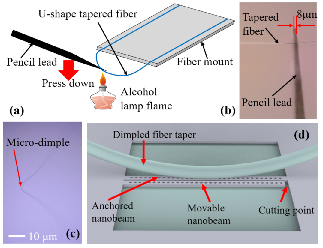
The coupled PCN cavity is optically coupled via a near-field probe consisting of a dimpled tapered optical fiber. The microdimple on the center of the tapered fiber can avoid high optical loss and bad coupling efficiency arising from the large contact length with the device. Figure 3a shows the dimpling process. An 8 μm polished pencil lead is used to press against the fiber taper tightly (see Figure 3b). Afterward, a microflame is employed to heat the contact point for about 2 s. Finally, the tapered fiber and pencil lead tip are separated carefully, and the dimpled tapered fiber with a diameter of 1 µm and a nominal radius of curvature of 25 µm is prepared for the near-field evanescent coupling, as shown in Figure 3c. With the dimpled optical fiber taper evanescently coupled with the nanocavity, light is pumped into the nanocavity from a tunable laser source and extracted back out. As seen in Figure 3d, the tapered fiber is brought in optical contact with the PCN device and aligned in parallel to the nanobeams. It should be noted that the fiber taper is physically attached to the rigid side of the anchored PCN cavity. The dimple is positioned in contact with the top surface of the fixed nanobeam so that there is no impact on the mechanical motion of the movable nanobeam.
3.3. Fiber Taper Measurement Setup
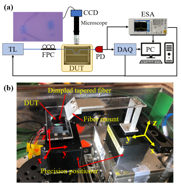
In this work, fiber taper evanescently coupled with a PCN cavity is employed in a vacuum environment (with a vacuum pressure of about 8.6 mBar), as illustrated in Figure 4a. The input laser light from the tunable laser (TL, Santec TSL510, Yamanashi, Japan) is selectively adjusted to excite transverse electric (TE) mode through a fiber polarizer controller (FPC) to ensure efficient optical coupling between the fiber taper and the cavity. Afterward, the output TE-polarized light is launched into the coupled PCN cavity (device under test (DUT)) by the physical touch of the dimpled fiber taper and DUT. The escaped light from the cavity is coupled back into the fiber taper. The transmitted optical power through the fiber taper is then measured by a high-speed photodetector (PD, Newport 1802, Irvine, CA, USA) and is split into two channels. To characterize the optical properties of the coupled PCN cavity, one channel signal is connected with the data acquisition device (DAQ). Synchronization is established between the DAQ and TL to ensure the wavelength sweeping of the tunable laser. The other channel signal is implemented to measure the mechanical properties of the coupled PCN cavity using an electrical signal analyzer (ESA, Agilent N9020A, Santa Clara, CA, USA). In the detection of mechanical spectra, the wavelength of the laser should be set and swept near the cavity resonance by simultaneously controlling ESA and TL. Both optical and mechanical spectra data are finally processed in the computer. It should be noted that all measurements are operated in the vacuum chamber, as shown in Figure 4b. The precise alignment of the PCN cavity and fiber taper is achieved by a pair of miniature piezoelectric positioners (Mechonics MX 35, München, Germany).
4. Results and Analysis
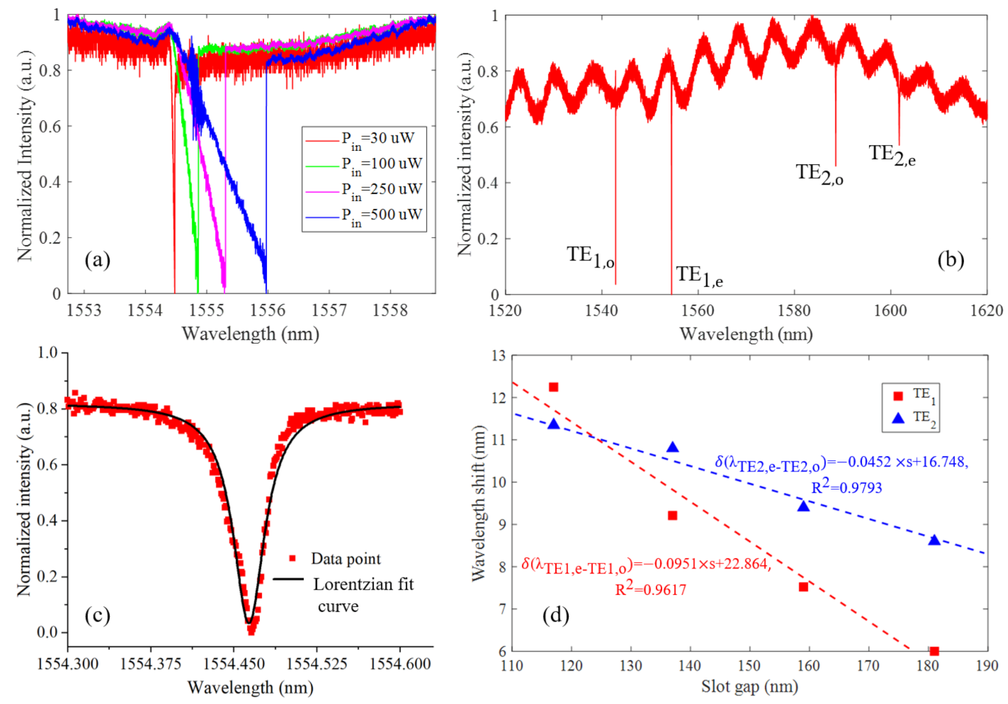
Using the measurement setup in Figure 4, the performance of the proposed coupled PCN cavity is justified by observing the resonance of the cavity. First, to diminish the thermo-optic effect on the intercavity and ensure a Lorentzian transmission spectrum, as shown in Figure 5a, the optimal light pumped into the PCN cavity is calibrated as . As light reduces from 500 to 20 , it can be seen that the shape of the resonance is gradually adjusted to a symmetrical morphology in line with a Lorentzian curve. Due to the high transmittance of the dimpled fiber taper, the first and second supermodes are observed in the transmission spectrum with the tunable laser sweeping from 1520 to 1620 nm. Figure 5b reveals that the fundamental supermodes TE1,o () and TE1,e (), as well as the second supermodes TE2,o () and TE2,e (), are observed in the spectrum. Overall, these experimental wavelengths comply with simulated results with a small deviation due to the imperfect fabrication. Furthermore, using Lorentzian fitting in the fundamental even mode, as presented in Figure 5c, the experimental total Q-factor of resonance is justified as 4.49 × 10⁴. Similarly, the measured Q-factors of the other fundamental odd mode, the second odd and even mode are identified as 5.61 × 10⁴, 3.53 × 10⁴ and 1.60 × 10⁴, respectively. In addition, four groups of coupled PCN cavities with a slot gap ranging from 117 to 182 nm are experimentally demonstrated, as shown in Figure 5d. Considering the inconsistency between various devices, here, the wavelength difference shift between the even and odd fundamental and second modes are taken to evaluate the optomechanical coupling strength. These measured results agree well with the simulated measurement in Figure 2, and the optomechanical coupling constant can be determined by the slope of the gap-dependent dispersion curve. Here, we focus on the fundamental even mode, and its optomechanical coupling constant is calculated to be by the approximate linear fitting.
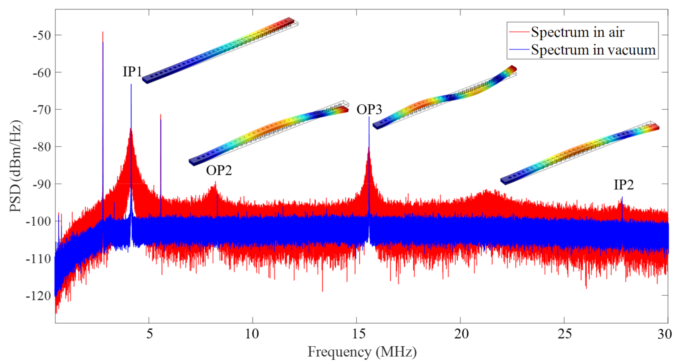
As mentioned above, the high optical Q-factor of the resonance contributes to optical force between two nanobeams and thus drives the optomechanical oscillation. More specifically, in this coupled PCN cavity, we focus on the optical force arising from the even mode to drive the movable nanobeam toward an in-plane movement. Therefore, by setting the wavelength of the pump light at the shoulder of the optical resonance, an optical-force-induced temporal mechanical oscillation can be observed by the power spectrum density (PSD) of the transmitted optical intensity with an electric signal analyzer (ESA). As shown in Figure 6, several mechanical motion modes of the movable nanobeam in the ambient atmosphere and vacuum are observed. Compared with the finite-element-method (FEM) simulation results, two in-plane modes IP1 () and IP2 (), and two out-of-plane modes OP2 () and OP3 (), are identified with an effective mass . Therefore, the corresponding spring constant of the fundamental in-plane motion mode is calculated as , and hence its root-mean-square (RMS) motion amplitude is inferred as . In addition, it is very clear that mechanical linewidths of the mechanical modes are vastly different in air and vacuum conditions. For example, based on Lorentzian fitting, the mechanical Q-factor () of the fundamental in-plane motion mode IP1 in the ambient atmosphere is obtained as ~25 with a linewidth of , which is limited by the air damping in the ambient environment. However, in the vacuum measurement, the mechanical linewidth of IP1 mode is dramatically suppressed to 1.5 kHz, and thus its mechanical Q-factor reaches up to 2.76 × 10³.
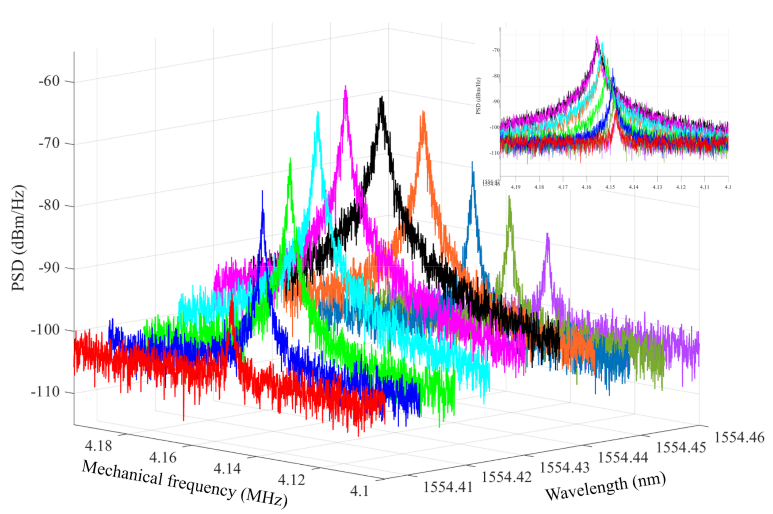
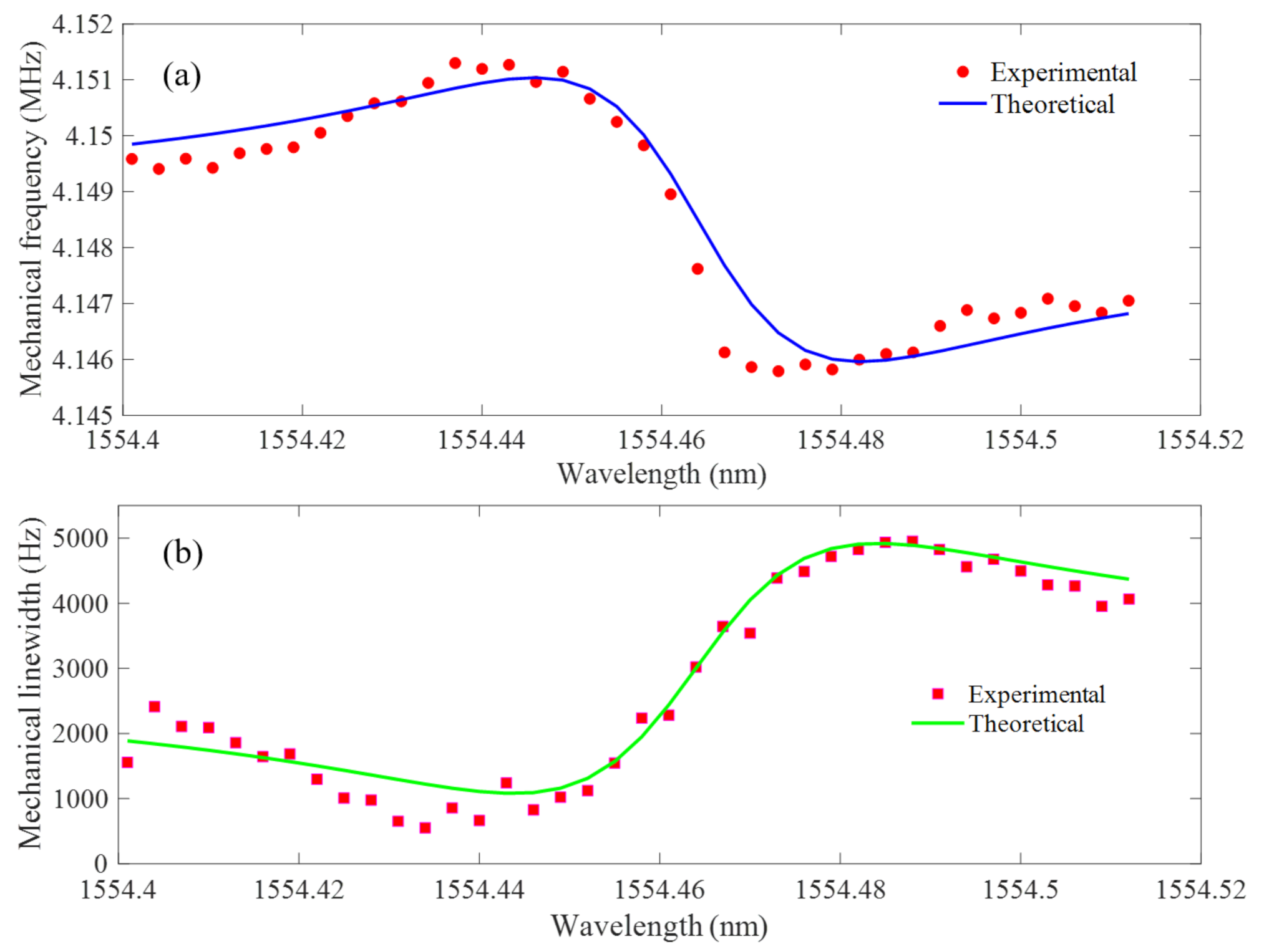
In this optomechanical coupled PCN cavity, the optical force created by the photon inside the intercavity not only drives the in-plane motion of movable nanobeam but can also modify the effective rigidity (optical spring effect) and effective mechanical loss (damping effect) as a function of laser-cavity detuning (). To experimentally characterize these effects, the wavelength of the pump light () should be set aside the resonance () first and then scan across the optical resonance. In the blue-detuned () regime, as the measured mechanical spectra presented in Figure 6, both the mechanical frequency and linewidth of the IP1 motion mode vary as the function of the input laser wavelength. As the laser wavelength approaches optical resonance, the mechanical spectrum shifts as the laser detuning (see the inset in Figure 7) with accompany of the linewidth narrowing and broadening. On the one hand, the mechanical frequency shifts with to modify the effective rigidity, attributed to the optical spring effect. On the other hand, the linewidth changes because the optical force causes antidamping and damping in the blue-detuned regime. Total adjustment of the mechanical frequency and linewidth of the IP1 mode is obtained as shown in Figure 8 with the laser sweeping across the optical resonance. In this work, the proposed optomechanical PCN cavity is performed in the unresolved sideband (). Optical stiffening and linewidth narrowing of the IP1 mode are observed under the blue-detuned laser pumping. Conversely, optical softening of the IP1 mode and linewidth broadening are monitored in the red-detuned laser excitation. Both curve fittings in Figure 8a,b are according to Equations (2) and (3), respectively, where all numerical parameters are obtained from the experimental results in this optomechanical system. It can be seen that the experimental results have good agreement with the theoretical fitting, which indicates that the optical spring and damping effects of the movable nanobeam are generated from the strong optomechanical coupling-induced optical force. In other words, the thermo-optic effect caused by the heat in the input light is so weak that it can be negligible in this work.
Considering that the mechanical frequency and linewidth of the in-plane mechanical mode are sensitive to laser-cavity detuning, it can therefore be applied in high-precision motion sensing with an improved resolution. Furthermore, the motion of the suspended flexible nanobeam can be integrated with potential mechanical schemes, and it could be exploited in the detection of applied external signals. Instead of monitoring wavelength variation in the traditional optical dispersion-sensing method [28], this optomechanical sensing principle concentrates on detecting the mechanical oscillation of the movable nanobeam. Due to the optical-force-driven mechanical movement of the flexible nanobeam, the optomechanical coupling is modulated by the slot gap variation. Under laser-cavity detuning, the mechanical frequency of the in-plane motion can be modified, attributed to the optical spring effect in the unresolved sideband. Referring to the experimental results in Figure 8a, an approximately linear slope of frequency shift versus laser detuning near the optical resonant wavelength can be calculated as =271.37 kHz/nm. In this case, is caused by the mechanical motion, and a 1 nm displacement of the movable nanobeam results in a mechanical frequency shift of about 270 kHz. As a result, the variation of mechanical frequency is obtained as , where optical dispersion change is amplified and converted to the mechanical response of the in-plane mode. On account of the critical parameters of the optomechanical system, the minimal detectable wavelength shift can be determined as , finally yielding the sensing resolution of . This enhanced sensing resolution is competitive and even much higher than that achieved in conventional optical dispersion methods as long as the proposed optomechanical system could be equipped with higher optical and mechanical Q-factors and optomechanical coupling strength.
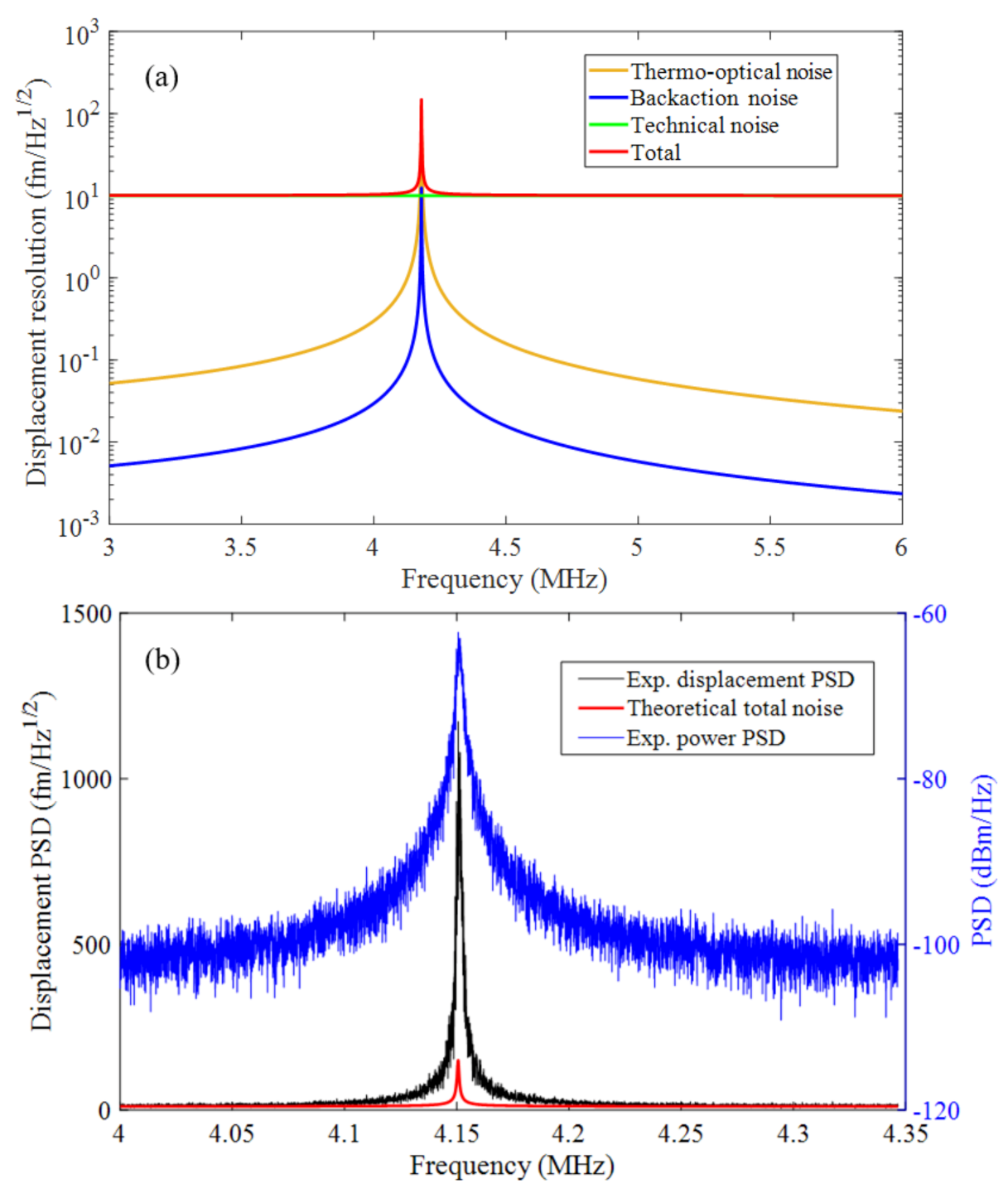
Furthermore, noise of the optomechanical system is analyzed to extract the displacement sensitivity. Here, displacement-noise PSD arises from the contributions of thermal Brownian motion noise , optical shot noise , detector noise and backaction noise [7,29]. Therefore, total displacement-noise PSD can be represented as,
where is Planck’s constant, ηqe is the quantum efficiency of a photodiode, is optomechanical gain with the transmission ratio = 0.6, NEP is noise-equivalent-power and NEP = 2.5 pW/ for the Newport 1811 detector. Based on the realistic parameters of the proposed optomechanical coupled PCN cavity at room temperature, these sources of noise (here, two frequency-independent noises and are joint and called technical noise) in Equation (5) are calculated and visualized in Figure 9a. It can be seen that thermal fluctuation noise dominates all other noises near the mechanical resonance of IP1 at room temperature. Furthermore, noise floor (the green line in Figure 9a) defined by the technical noise near the mechanical resonance is obtained as 30 . Therefore, on account of all noises in the optomechanical PCN cavity, the mechanical displacement sensitivity of the movable nanobeam is evaluated as 150 . An experimental noise assessment is performed by fixing the input laser at this shoulder of optical resonance to observe the spectrum response near the mechanical resonance. As shown in Figure 9b, the experimental displacement PSD is obtained by converting the power PSD using the optomechanical gain. At the mechanical resonance of the IP1 mode, a maximum displacement amplitude of 1468 is observed, and it is about 10 times larger than the theoretical total noise (the red line in Figure 9b). As given in Equation (5), with a moderate optomechanical coupling and high performance of optical cavity, the improvements to enhance the displacement sensitivity should be dependent on a better optimization of the mechanical oscillator with a maximizing Qm and a reduced mass meff.
5. Conclusions
In this work, cavity optomechanics were experimentally demonstrated by observing the dynamical backaction behaviors of a movable nanobeam in a coupled PCN cavity. Due to the high performance of the optical Q-factor and flexible-mechanic-induced large optomechanical coupling coefficient , an optical-force-induced optical spring and damping effect were observed from the laser-detuned mechanical spectra. Benefiting from the high transmission efficiency of fiber taper–cavity coupling scheme, a lower optical input was required, and thus the thermal effect was vastly eliminated to enhance motion sensitivity. Compared with traditional dispersion sensing, this optical spring effect enhanced the minimal detectable wavelength shift up to on account of the linear slope of the frequency shift versus laser detuning as ~271.37 kHz/nm. Furthermore, analysis on the displacement PSD and noise of the optomechanical system preliminarily proved that a maximized in-plane motion of 1428 fm/ of the movable nanobeam could be achieved with a mechanical motion sensitivity of 150 . In the future, engineering design and integration with micro-electromechanical systems on the proposed optomechanical nanocavity could enable more extensive applications using the demonstrated motion-sensing mechanism.
Author Contributions
J.X. conducted the conceptualization, validation and investigation and write this manuscript; F.W., C.C. and Z.H. checked and edited language and formal; H.Y. and S.X. supervised this work. All authors have read and agreed to the published version of the manuscript.
Funding
This research was funded by the National Natural Science Foundation of China (NSFC) with grant number 61905283.
Conflicts of Interest
The authors declare no conflict of interest.
References
- Albarelli, F.; Ferraro, A.; Paternostro, M.; Paris, M.G. Nonlinearity as a resource for nonclassicality in anharmonic systems. Phys. Rev. A 2016, 93, 032112. [Google Scholar] [CrossRef] [Green Version]
- Aspelmeyer, M.; Kippenberg, T.J.; Marquardt, F. Cavity optomechanics. Rev. Mod. Phys. 2014, 86, 1391. [Google Scholar] [CrossRef]
- Hu, Y.-W.; Xiao, Y.-F.; Liu, Y.-C.; Gong, Q. Optomechanical sensing with on-chip microcavities. Front. Phys. 2013, 8, 475–490. [Google Scholar] [CrossRef]
- Wu, M.; Hryciw, A.C.; Healey, C.; Lake, D.P.; Jayakumar, H.; Freeman, M.R.; Davis, J.P.; Barclay, P.E. Dissipative and dispersive optomechanics in a nanocavity torque sensor. Phys. Rev. X 2014, 4, 021052. [Google Scholar] [CrossRef] [Green Version]
- Hajisalem, G.; Losby, J.E.; de Oliveira Luiz, G.; Sauer, V.T.; Barclay, P.E.; Freeman, M.R. Two-axis cavity optomechanical torque characterization of magnetic microstructures. New J. Phys. 2019, 21, 095005. [Google Scholar] [CrossRef]
- Wu, M.; Hryciw, A.C.; Khanaliloo, B.; Freeman, M.R.; Davis, J.P.; Barclay, P.E. Photonic Crystal Paddle Nanocavities for Optomechanical torsion Sensing. In Proceedings of the CLEO: Science and Innovations, San Jose, CA, USA, 6–11 May 2012. [Google Scholar]
- Krause, A.G.; Winger, M.; Blasius, T.D.; Lin, Q.; Painter, O. A high-resolution microchip optomechanical accelerometer. Nat. Photonics 2012, 6, 768. [Google Scholar] [CrossRef] [Green Version]
- Cervantes, F.G.; Kumanchik, L.; Pratt, J.; Taylor, J. Self-calibrating ultra-low noise, wide-bandwidth optomechanical accelerometer. Appl. Phys. Lett. 2014, 104, 221111. [Google Scholar]
- Huang, Y.; Flor Flores, J.G.; Li, Y.; Wang, W.; Wang, D.; Goldberg, N.; Zheng, J.; Yu, M.; Lu, M.; Kutzer, M. A Chip-Scale Oscillation-Mode Optomechanical Inertial Sensor Near the Thermodynamical Limits. Laser Photonics Rev. 2020, 14, 1800329. [Google Scholar] [CrossRef] [Green Version]
- Wong, C.W.; Li, Y.; Zheng, J.; Rogers, D. Apparatus for Measuring Gravitational Force and Methods of Using the Same. Google Patents 4 April 2013. [Google Scholar]
- Safavi-Naeini, A.H.; Gröblacher, S.; Hill, J.T.; Chan, J.; Aspelmeyer, M.; Painter, O. Squeezed light from a silicon micromechanical resonator. Nature 2013, 500, 185–189. [Google Scholar] [CrossRef] [Green Version]
- Cohen, J.D.; Meenehan, S.M.; Painter, O. Optical coupling to nanoscale optomechanical cavities for near quantum-limited motion transduction. Opt. Express 2013, 21, 11227–11236. [Google Scholar] [CrossRef] [Green Version]
- Kaviani, H.; Healey, C.; Wu, M.; Ghobadi, R.; Hryciw, A.; Barclay, P.E. Nonlinear optomechanical paddle nanocavities. Optica 2015, 2, 271–274. [Google Scholar] [CrossRef] [Green Version]
- Paraïso, T.K.; Kalaee, M.; Zang, L.; Pfeifer, H.; Marquardt, F.; Painter, O. Position-squared coupling in a tunable photonic crystal optomechanical cavity. Phys. Rev. X 2015, 5, 041024. [Google Scholar] [CrossRef] [Green Version]
- Corbitt, T.; Ottaway, D.; Innerhofer, E.; Pelc, J.; Mavalvala, N. Measurement of radiation-pressure-induced optomechanical dynamics in a suspended Fabry-Perot cavity. Phys. Rev. A 2006, 74, 021802. [Google Scholar] [CrossRef] [Green Version]
- Schliesser, A.; Kippenberg, T.J. Cavity optomechanics with whispering-gallery mode optical micro-resonators. Adv. At. Mol. Opt. Phys. 2010, 58, 207–323. [Google Scholar]
- Goyal, A.K.; Dutta, H.S.; Pal, S. Recent advances and progress in photonic crystal-based gas sensors. J. Phys. D Appl. Phys. 2017, 50, 203001. [Google Scholar] [CrossRef]
- Qiao, Q.; Xia, J.; Lee, C.; Zhou, G. Applications of photonic crystal nanobeam cavities for sensing. Micromachines 2018, 9, 541. [Google Scholar] [CrossRef] [Green Version]
- Yang, D.-Q.; Duan, B.; Liu, X.; Wang, A.-Q.; Li, X.-G.; Ji, Y.-F. Photonic crystal nanobeam cavities for nanoscale optical sensing: A review. Micromachines 2020, 11, 72. [Google Scholar] [CrossRef] [Green Version]
- Favero, I.; Marquardt, F. Focus on optomechanics. New J. Phys. 2014, 16, 085006. [Google Scholar] [CrossRef]
- Wu, M.; Wu, N.L.-Y.; Firdous, T.; Sani, F.F.; Losby, J.E.; Freeman, M.R.; Barclay, P.E. Nanocavity optomechanical torque magnetometry and radiofrequency susceptometry. Nat. Nanotechnol. 2017, 12, 127–131. [Google Scholar] [CrossRef]
- Zhang, X.; Lin, T.; Tian, F.; Du, H.; Zou, Y.; Chau, F.S.; Zhou, G. Mode competition and hopping in optomechanical nano-oscillators. Appl. Phys. Lett. 2018, 112, 153502. [Google Scholar] [CrossRef]
- Chan, J.; Eichenfield, M.; Camacho, R.; Painter, O. Optical and mechanical design of a “zipper” photonic crystal optomechanical cavity. Opt. Express 2009, 17, 3802–3817. [Google Scholar] [CrossRef] [PubMed] [Green Version]
- Eichenfield, M.; Camacho, R.; Chan, J.; Vahala, K.J.; Painter, O. A picogram-and nanometre-scale photonic-crystal optomechanical cavity. Nature 2009, 459, 550–555. [Google Scholar] [CrossRef] [PubMed] [Green Version]
- Quan, Q.; Deotare, P.B.; Loncar, M. Photonic crystal nanobeam cavity strongly coupled to the feeding waveguide. Appl. Phys. Lett. 2010, 96, 203102. [Google Scholar] [CrossRef] [Green Version]
- Quan, Q.; Loncar, M. Deterministic design of wavelength scale, ultra-high Q photonic crystal nanobeam cavities. Opt. Express 2011, 19, 18529–18542. [Google Scholar] [CrossRef] [Green Version]
- Li, Q.; Wang, T.; Su, Y.; Yan, M.; Qiu, M. Coupled mode theory analysis of mode-splitting in coupled cavity system. Opt. Express 2010, 18, 8367–8382. [Google Scholar] [CrossRef]
- Qiao, Q.; Peng, C.; Xia, J.; Lee, C.; Zhou, G. Ultra-small photonic crystal (PhC)-based test tool for gas permeability of polymers. Opt. Express 2019, 27, 35600–35608. [Google Scholar] [CrossRef]
- Wu, M. Nanophotonic Optomechanical Devices for Torque Magnetometry; University of Calgary: Calgary, AB, Canada, 2016. [Google Scholar]
Figure 1.
Cavity structure and simulated optical mode field profiles. (a) Schematic of the coupled photonic crystal nanobeam (PCN) cavity, with the unit cell section shown in (a-1), dimensions: Si layer thickness t, lattice constant a, width w, and hole radius r, and with the SEM photograph of the cavity center shown in (a-2), dimension: gap separation s; (b) FDTD simulation of the first two orders of the electrical field (Ey) mode profiles, with the center dotted red line indicating the location of the center air hole; (c) top-view SEM image of the coupled PCN cavity with the slot gap of 117 nm.

Figure 2.
FDTD simulation of the first and second-order supermode resonance wavelength tuning versus the coupling gap.
Figure 2.
FDTD simulation of the first and second-order supermode resonance wavelength tuning versus the coupling gap.

Figure 3.
Dimpled tapered fiber fabrication and evanescent coupling method. (a) Dimpling process; (b) microphotograph of the polished wedge-shaped pencil lead pressing against the tapered fiber; (c) microphotograph of the dimple at the center of U-shape tapered fiber; (d) schematic diagram of near-field coupling position between fiber taper and PCN cavity.

Figure 4.
(a) Experimental system (light-yellow rectangular box indicates the device under test (DUT) test in the vacuum chamber); (b) alignment setup of the fiber taper-DUT under a vacuum chamber.
Figure 4.
(a) Experimental system (light-yellow rectangular box indicates the device under test (DUT) test in the vacuum chamber); (b) alignment setup of the fiber taper-DUT under a vacuum chamber.

Figure 5.
Optical characterization of the coupled PCN cavities. (a) Nonlinear transmission response under different pump light power; (b) transmission spectrum of the coupled PCN cavity; (c) resonance dip at the TE1,e mode with Lorentzian fitting; (d) resonant wavelength difference shift varying with slot gaps.

Figure 6.
Mechanical spectra measurement in the ambient atmosphere and vacuum condition. The insets indicate the measured mechanical mode with their FEM profiles (including two in-plane motion modes IP1 and IP2 and two out-of-plane motion modes OP2 and OP3).
Figure 6.
Mechanical spectra measurement in the ambient atmosphere and vacuum condition. The insets indicate the measured mechanical mode with their FEM profiles (including two in-plane motion modes IP1 and IP2 and two out-of-plane motion modes OP2 and OP3).

Figure 7.
Mechanical spectra measurements with laser detuning in vacuum condition. The inset shows peak shape of the spectrum varies with laser detuning.
Figure 7.
Mechanical spectra measurements with laser detuning in vacuum condition. The inset shows peak shape of the spectrum varies with laser detuning.

Figure 8.
Mechanical frequency (a) and linewidth (b) of the mechanical motion mode IP1 as a function of laser detuning around the wavelength of 1554.464 nm. Both theoretical fitting curves are calculated using , and from the experiment (, , , , , ).
Figure 8.
Mechanical frequency (a) and linewidth (b) of the mechanical motion mode IP1 as a function of laser detuning around the wavelength of 1554.464 nm. Both theoretical fitting curves are calculated using , and from the experiment (, , , , , ).

Figure 9.
Noise analysis of the optomechanical coupled PCN cavity. (a) Theoretical calculation of the frequency response of different noise sources; (b) experimental noise around the IP1 mode.
Figure 9.
Noise analysis of the optomechanical coupled PCN cavity. (a) Theoretical calculation of the frequency response of different noise sources; (b) experimental noise around the IP1 mode.

Publisher’s Note: MDPI stays neutral with regard to jurisdictional claims in published maps and institutional affiliations. |
© 2021 by the authors. Licensee MDPI, Basel, Switzerland. This article is an open access article distributed under the terms and conditions of the Creative Commons Attribution (CC BY) license (https://creativecommons.org/licenses/by/4.0/).
Share and Cite
MDPI and ACS Style
Xia, J.; Wang, F.; Cao, C.; Hu, Z.; Yang, H.; Xiong, S. A Nanoscale Photonic Crystal Cavity Optomechanical System for Ultrasensitive Motion Sensing. Crystals 2021, 11, 462. https://0-doi-org.brum.beds.ac.uk/10.3390/cryst11050462
AMA Style
Xia J, Wang F, Cao C, Hu Z, Yang H, Xiong S. A Nanoscale Photonic Crystal Cavity Optomechanical System for Ultrasensitive Motion Sensing. Crystals. 2021; 11(5):462. https://0-doi-org.brum.beds.ac.uk/10.3390/cryst11050462
Chicago/Turabian StyleXia, Ji, Fuyin Wang, Chunyan Cao, Zhengliang Hu, Heng Yang, and Shuidong Xiong. 2021. "A Nanoscale Photonic Crystal Cavity Optomechanical System for Ultrasensitive Motion Sensing" Crystals 11, no. 5: 462. https://0-doi-org.brum.beds.ac.uk/10.3390/cryst11050462
Note that from the first issue of 2016, this journal uses article numbers instead of page numbers. See further details here.