Article

All-Fiber Frequency Shifter Based on an Acousto-Optic Tunable Filter Cascaded with a Tapered Fiber-Coupled Microcavity

1
MOE Key Laboratory of Weak-Light Nonlinear Photonics, TEDA Applied Physics Institute and School of Physics, Nankai University, Tianjin 300457, China
2
Institute of Optoelectronic Engineering, College of Physics & Optoelectronics, Taiyuan University of Technology, Taiyuan 030024, China
3
Collaborative Innovation Center of Extreme Optics, Shanxi University, Taiyuan 030006, China
4
MOE Key Laboratory of Material Physics and Chemistry under Extraordinary Conditions and Shanxi Key Laboratory of Optical Information Technology, School of Science, Northwestern Polytechnical University, Xi’an 710072, China
*
Authors to whom correspondence should be addressed.
These authors contributed equally to this article.
Submission received: 29 March 2021 / Revised: 22 April 2021 / Accepted: 23 April 2021 / Published: 1 May 2021
(This article belongs to the Special Issue Micro and Nano Optics for Advanced Sensing Technology)

Abstract

:
An all-fiber acousto-optic frequency shifter (AOFS) based on an acousto-optic tunable filter (AOTF) cascaded with a packaged tapered fiber (TF)-coupled microsphere was proposed and demonstrated in both theory and experiment. The configuration has the advantages of easy alignment, robustness, compact size, and low cost, which will improve its further application, such as in the optical heterodyne detection technique (OHDT).

1. Introduction

The optical heterodyne detection technique (OHDT) has the advantages of high sensitivity, high accuracy, and strong anti-interference ability, and it plays an important role in fields including fine spectrometry [1], vector hydrophone [2], infrared radar, nanoparticle detection [3,4], optical communications [5], and so on [6,7]. The key component of the OHDT is a frequency shifter, which generates the signal light with a small frequency shift compared to the reference light. Typically, the acousto-optic effect is utilized to realize this. Compared with optical Bragg cells or integrated surface acoustic wave (SAW)-driven waveguides [8,9], all-fiber acousto-optic frequency shifters (AOFS) [10,11,12,13,14,15,16], especially those based on a single-mode fiber (SMF), are preferred due to the lower driving power, smaller frequency shift, and lower cost determined by their all-fiber feature. The acoustic wave applied to the fiber could be either a longitudinal wave or a flexible wave. A typical longitudinal acoustic wave was applied to modulate a fiber Bragg grating (FBG) and induced an all-fiber acousto-optic super-lattice modulation structure [17,18,19,20], in which the input light could be reflected by the modulated narrow side band of the FBG and be converted to the backward core mode with a frequency shift. To achieve reasonably good efficiency, the FBG used had to be up to 50 mm, which was difficult to prepare and therefore expensive [21,22]. An acoustic flexible wave was applied universally in an all-fiber acoustic-optic structure [23,24,25] because of its simple structure and high efficiency. It could convert the core mode to the forward cladding mode with a frequency shift in a piece of SMF covering a broad spectral range. However, to utilize the cladding mode as the signal light in OHDT, a mode converter or a mode stripper is necessary. This is the key element when utilizing an acoustic flexible wave to construct a frequency shifter. To date, various methods have been proposed to realize AOFSs, including cascading all-fiber acousto-optic structures with a long period fiber grating [15], parallel coupled tapered fiber (TF) [16], or another acousto-optic structure. However, none of these methods is compact in size. This situation changed with the development of the whispering gallery mode resonators (WGMRs), whose size was only of hundreds of micrometers. In 2016, mode conversion between the high-order cladding mode and the core mode was demonstrated in the C-band [26] and various theories and applications were developed thereafter [27,28]. With a WGMR, compact and low-cost AOFS could be expected.
In this work, we demonstrate an AOFS by cascading a typical all-fiber acousto-optic tunable filter (AOTF) and a compact mode converter based on a TF-coupled microsphere. The AOTF provided the frequency shift as it coupled the core mode to the cladding mode, and the TF-coupled microsphere converted the cladding mode with the frequency shift back to the core of the SMF. The package process was also developed to make the coupling stable. Stable beats could be observed in the packaged structure by interfering the signal light out of the AOFS with the reference light. The AOFS reported in the work was not only compact and robust but also broad-band applicable due to the tunability of the AOTF and the dense modes of the whispering gallery mode (WGM) in the microsphere, which made it much more applicable for future applications.

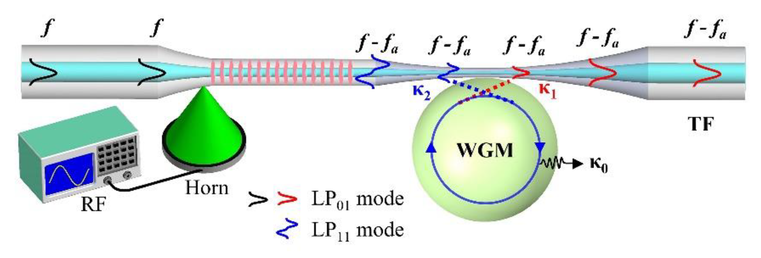
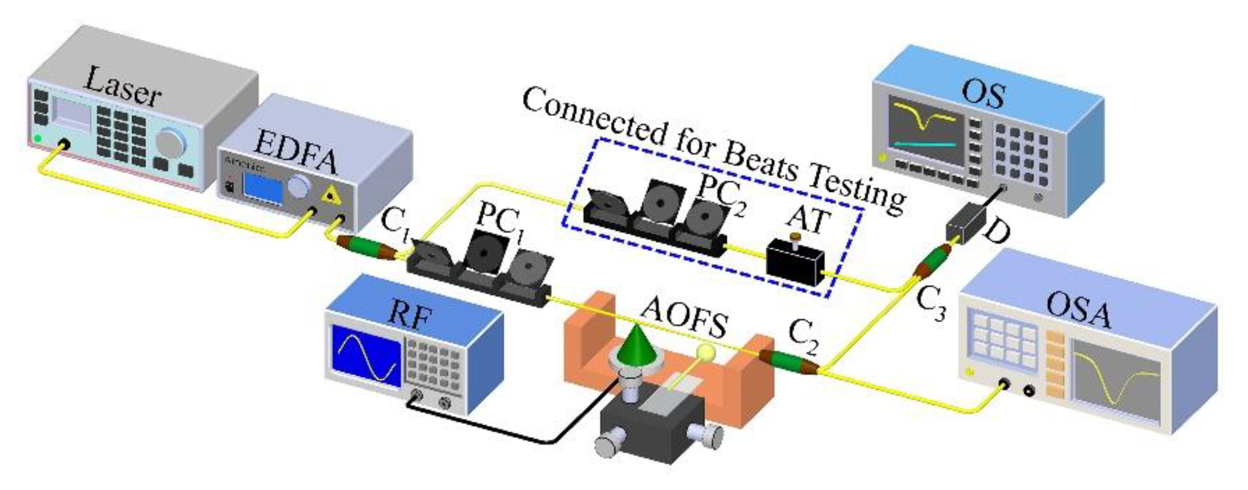
2. Methods and Configuration

The structure of the proposed AOFS is shown in Figure 1. A typical AOTF is used to convert the core mode LP01 to the cladding mode LP11, which consists of a piece of stripped SMF and an acoustic horn with a piece of piezoelectric transducer (PZT) and an acoustic wave absorber attached at its bottom [29]. When a radio frequency (RF) signal is applied to the PZT, an acoustic wave will be generated and then magnified by the acoustic horn, and it will propagate along the stripped SMF. The LP01 mode at the resonant wavelength will be converted to the cladding mode—typically, the LP11 mode—when the phase matching condition is satisfied:
λ = ( n 01 n 11 ) · Λ
where λ is the resonant central wavelength of AOTF; n01 and n11 are the effective indexes of the LP01 mode and the LP11 mode, respectively; Λ is the wavelength of the acoustic wave in the stripped SMF. The typical bandwidth of the mode conversion could be from 0.1 nm to tens of nanometers according to the acousto-optic interaction length and the diameter of the SMF [30], but, allowing for the tuning feature of the AOTF, it can easily cover the entire spectral range of the C-band. The converted LP11 mode will gain a negative frequency shift fa that is the same as the frequency of the acoustic wave.
After the AOTF, there is a TF-coupled WGMR to convert the LP11 mode back to the LP01 mode. The mechanism is already presented in our previous work [26]. The conversion efficiency could be presented as below:
D = 4 κ 1 κ 2 ( κ 0 + κ 1 + κ 2 ) 2
where κ1 is the coupling loss to the LP01 mode of the WGM, κ2 is the coupling loss to the LP11 mode of the WGM, and κ0 is the intrinsic loss of the WGM in the microcavity, which is determined by the WGM cavity itself—that is, the absorption of the material, the scattering of the residual inhomogeneity, the curvature and roughness of its surface and so on. The ideal conversion efficiency could be up to ~100% in a high-Q WGM with the following condition fulfilled:
κ 1 = κ 2 κ 0
Generally speaking, the condition of Equation (3) could be realized easily in a high-Q WGMR—for example, a fused silica microsphere whose Q value could be up to 108 and κ0 is usually much smaller than κ1 and κ2. It is possible for us to make κ1 = κ2 in the experiment by optimizing the coupling position of the WGMR along the two-mode coupling TF as reported in previous work [26].
In principle, the conversion efficiency could be very high. However, several problems have to be considered in practice.
One of the most important aspects is that both the conversion efficiency of the AOTF and the TF-coupled WGMR (microsphere) are polarization-dependent. The coupling loss in Equations (2) and (3) is dependent on the polarization. It is difficult to modify both the input polarization of the AOTF and that of the mode converter to their best performance at the same time, especially the latter, which is determined by the polarization of the LP11 mode. Meanwhile, all the polarizations of the modes, including the WGM, the LP01 mode and the LP11 mode, can only approximately be treated as linear polarizations. For example, the LP11 mode actually includes the TE01, TM01 and HE21 modes, which are of different refractive indices and polarizations. However, since WGM could be approximately treated as linear polarization, it could convert the fiber mode component of the same polarization, and the perpendicular components would remain as background at the same time. In principle, a suitable polarizer could filter the background out. Since OHDT is based on stable phase modulation, the background will not ruin its application and optimization is not necessary.
On the other hand, it is beneficial that the conversion of the TF-coupled WGM cavity is bidirectional. After the mode conversion in a compact AOTF, the LP01 mode may remain in the fiber core due to the limited acousto-optic (AO) efficiency from either the short AO interaction length or insufficient driving power to the acoustic transducer. Note that the bandwidth of a WGM is usually much larger than the frequency shift introduced by the AOTF; the remaining light of the LP01 mode after AOTF could still interact with the WGM, and the part of the same polarization as that of the WGM could be converted back to the LP11 mode via WGM. As a result, the AOTF in the AOFS does not need to be of very high conversion efficiency and it could be fabricated to be even shorter.
From the above analysis, it is possible for us to utilize a WGMR as a practical mode converter to build an AOFS for OHDT.

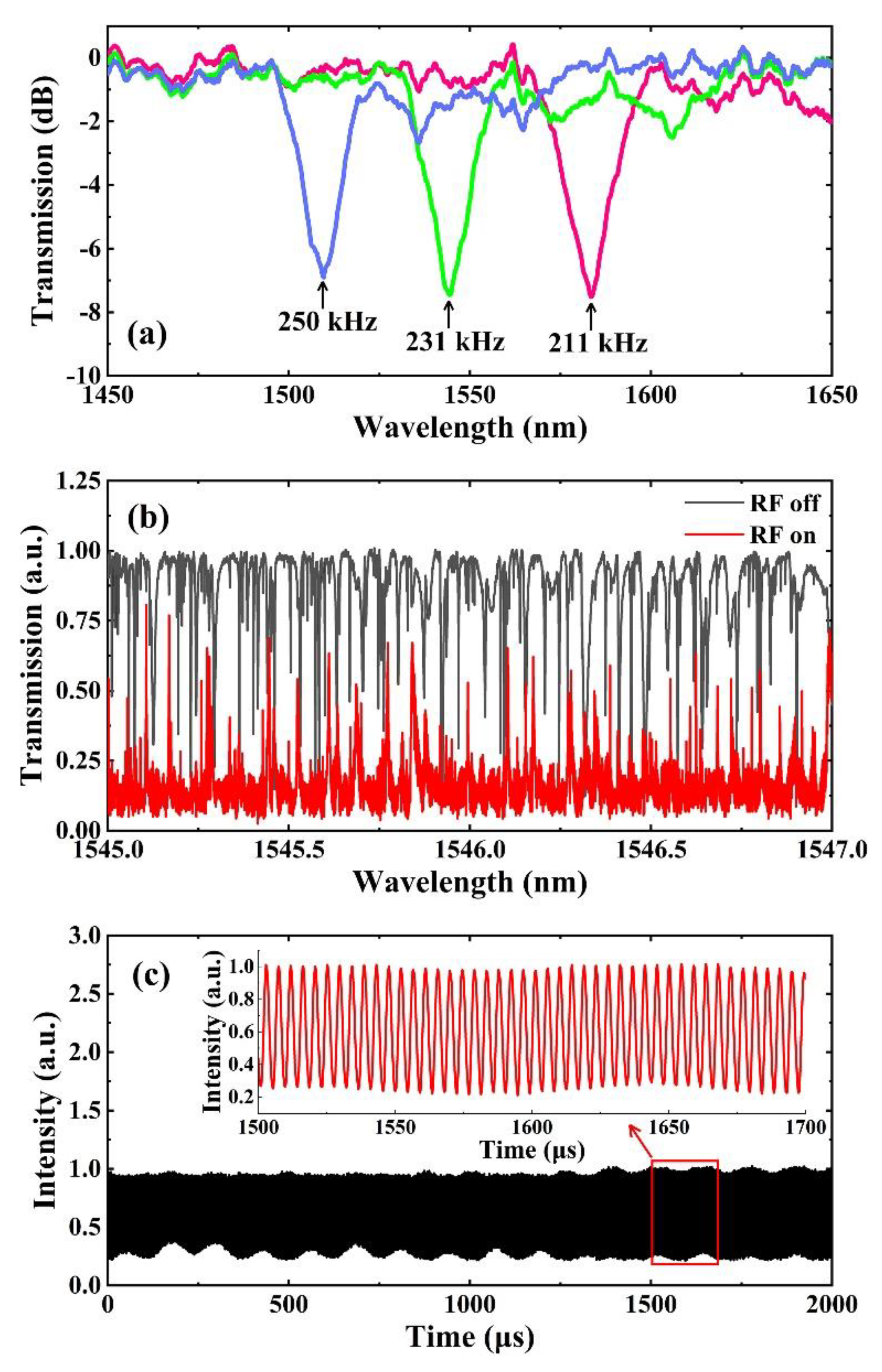
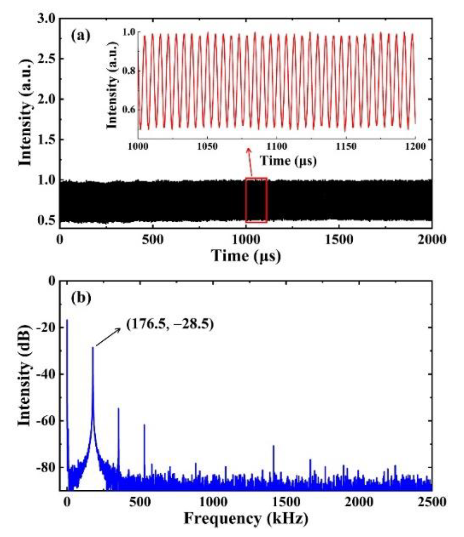
3. Experimental Results

The AOFS consists of an acoustic horn, fiber structure and a WGMR. According to our previous work, the diameter of the TF plays a crucial role in the construction of the mode convertor. The fiber structure used in the experiment was prepared based on a piece of SMF by a two-step tapering method. The first tapering would reduce the diameter of the fiber down to 55 μm to increase the AO effect [31]. The length of the uniform waist was approximately 8 cm. Then, the TF was tapered a second time to reduce its waist down to approximately 2.5 μm, close to one of its ends, which could be used for mode conversion. The total length of the structure was around 11 cm. Lastly, the acoustic horn was attached to the fiber structure to build a typical AOTF, with the horn and the WGMR at each end of the fiber. The WGMR used in the experiment was a microsphere made of silica, which was fabricated by fusing one cleaved end of SMF. To make the free spectrum range (FSR) small, the size of the microsphere should be prepared to be slightly larger—for example, with a diameter of around 250 μm—in the experiment. Most of the Q values of the WGMs in the microsphere were up to 107, which would ensure that the conditions of Equation (3) are valid.
The experimental configuration to demonstrate the proposed AOFS is shown in Figure 2. A tunable narrow-linewidth laser was followed by an erbium-doped fiber amplifier (EDFA), which could not only provide the amplification of the laser but was also used as a broad-band amplified spontaneous emission (ASE) source to calibrate the AOTF when the laser was off. After the EDFA, the light was split by a coupler C1. Part of the light from C1 was led into the AOFS structure via polarization controller PC1. The light after the AOFS was split again via the coupler C2, which was led into an optical spectrum analyzer (OSA) and another coupler C3, followed by an optical detector (D) connected to an oscilloscope (OS), respectively. Note that, at the beginning of the experiment, the polarization controller PC2 and an attenuator (AT) within the dotted lines in the figure were not connected so that the OS could be used to calibrate the coupling of the WGM. This part was connected only when the optical beats were tested in the OS to optimize the contrast of the beats.
At the beginning of the experiment, the microsphere was moved away from the TF and the laser was off, with only the EDFA on to ensure that the ASE light was functioning. With the RF signal applied, we could optimize PC1 to obtain a spectral notch of a typical AOTF in the OSA, which indicated that the light in the resonant LP01 mode was converted to the LP11 mode. As we changed the frequency of the RF signal, the resonant wavelength of the notch could be optimized. For example, as the RF signal was tuned from 211 kHz to 250 kHz, the center wavelength had a blue shift from 1583.4 nm to 1509.6 nm, as shown in Figure 3a. The efficiency of the AOTF was approximately 7 dB. With the laser on and the RF signal off, the microsphere was moved close to the TF and calibrated with a 3D-nano stage. The spectrum in the OS is shown as the black line in Figure 3b. With the RF on, the resonant cladding modes with a frequency shift activated by the AOTF were recoupled back into the fiber core by the microsphere so that a bandpass spectrum could be observed, shown as a red line in Figure 3b. The transferring efficiency could be up to around 80%. Not all the WGM modes could convert the fiber modes with such high efficiency, which was determined by its effective refractive index, as presented in previous work [26]. Note that, in order to enhance the conversion efficiency of the frequency-shifted signal, the polarization was optimized so that there was a slight wavelength difference between the resonant notches and peaks in the figure. To test the optical beats generated from the structure, we connected PC2 and AT within the dotted line box, as shown in Figure 2, and allowed the laser to work at the resonant wavelength. Optical beats could be observed in the OS. By adjusting the PC2 and the AT, the visibility of the optical beats could be optimized. The measured beats in the OS are shown in Figure 3c with unstable amplitude, which was mainly from the unstable coupling between the TF and the microsphere. To obtain a stable one, packaging of the microsphere was necessary.
Therefore, we tested optical beats in a packaged substitute. In the experiment, after we observed the spectra of the AOTF with the RF signal at 176.5 kHz, the RF signal was turned off. The specific calibration and package process could be described as four steps, as shown in Figure 4. First, the microsphere was suspended on a MgF2 substrate supported by a 3D-nano stage and we began its initial alignment to the TF with the help of the optical microscope and the 3D translation stage with the laser on, as shown in Figure 4a. Then, moderate ultraviolet (UV) epoxy was filled in the TF-microsphere coupling region drop by drop carefully, as shown in Figure 4b. Afterward, with the RF signal on to ensure that the AOTF was working, we moved the microsphere along the fiber until the bandpass spectrum was visible in the OS and then the coupling region was exposed under a UV lamp for around 120 s, as shown in Figure 4c. Lastly, the transition area of the TF was covered with UV epoxy and then cured with the UV lamp, as shown in Figure 4d. The total package area was around 1.9 cm.
After packaging the microsphere, with the loaded Q of the applied WGM being 7.27 × 10⁵, we could observe stable optical beats in the OS at a suitable optical wavelength, as shown in Figure 5a. The inset of Figure 5a is the magnification of the beat string. The frequency spectrum of the optical beats is shown in Figure 5b. Regardless of the direct current (DC) component, the optical beats were obviously of good signal to noise ratio and stable enough for OHDT. Note that the lower visibility was mainly from improper polarization, which will not negatively affect OHDT.

4. Conclusions

In conclusion, we have demonstrated an all-fiber AOFS based on an AOTF cascaded with a TF-coupled microsphere. It could be used to generate stable optical beats for OHDT. There was a DC component in the experiment, and theoretic analysis showed that it was mainly from improper polarization. With improved alignment or filtering of the background light with a polarizer, the DC part could be also reduced. In principle, the device could work within a broad band, not only because of the wide and dense applicable WGM distribution in a large spectrum range, but also because of the broadband tunability of the AOTF. Compared to the other methods, it has the advantages of compact size, robustness, simple alignment, low cost and stable performance, which will benefit its further applications.

Author Contributions

Conceptualization, F.G.; Data curation, X.H. and Y.H.; Formal analysis, J.L.; Funding acquisition, F.G.; Investigation, X.H., Y.H. and P.C.; Methodology, F.G.; Project administration, F.G.; Visualization, X.H.; Writing—original draft, X.H.; Writing—review & editing, F.G., X.D., F.B., W.Z., G.Z. and J.X. All authors have read and agreed to the published version of the manuscript.

Funding

This work was financially supported by the National Natural Science Foundation of China (the NSFC) (12074199, 11574161, 91750204, 11774182, 11974282 and 91950207), the CNKBRSF (2011CB922003) and the 111 Project (B07013).

Data Availability Statement

The data presented in this study are available on request from the corresponding author.

Conflicts of Interest

The authors declare no conflict of interest.

References

  1. Duran, V.; Djevarhidjian, L.; Chatellus, H. Bidirectional Frequency-Shifting Loop for Dual-Comb Spectroscopy. Opt. Lett. 2019, 44, 3789–3792. [Google Scholar] [CrossRef]
  2. Yang, P.; Xing, G.; He, L. Calibration of High-Frequency Hydrophone up to 40 MHz by Heterodyne Interferometer. Ultrason. 2014, 54, 402–407. [Google Scholar] [CrossRef] [PubMed]
  3. He, L.; Özdemir, Ş.; Zhu, J.; Kim, W.; Yang, L. Detecting Single Viruses and Nanoparticles Using Whispering Gallery Microlasers. Nat. Nanotechnol. 2011, 6, 428–432. [Google Scholar] [CrossRef] [PubMed] [Green Version]
  4. Donnarumma, D.; Brodoline, A.; Alexandre, D.; Gross, M. 4D Holographic Microscopy of Zebrafish Larvae Microcirculation. Opt. Express 2016, 24, 26887–26900. [Google Scholar] [CrossRef] [PubMed] [Green Version]
  5. Sandalidis, H.; Tsiftsis, T.; Karagiannidis, G. Optical Wireless Communications with Heterodyne Detection over Turbulence Channels with Pointing Errors. J. Lightwave Technol. 2009, 27, 4440–4445. [Google Scholar] [CrossRef]
  6. Kulkarni, G.; Reddy, K.; Zhong, Z.; Fan, X. Graphene Nanoelectronic Heterodyne Sensor for Rapid and Sensitive Vapour Detection. Nat. Commun. 2014, 5, 1–7. [Google Scholar] [CrossRef]
  7. Zhang, W.; Gao, W.; Huang, L.; Mao, D.; Jiang, B.; Gao, F.; Yang, D.; Zhang, G.; Xu, J.; Zhao, J. Optical Heterodyne Micro-Vibration Measurement Based on All-Fiber Acousto-Optic Frequency Shifter. Opt. Express 2015, 23, 17576–17583. [Google Scholar] [CrossRef]
  8. Abbiss, J.; Mayo, W. Deviation-Free Bragg Cell Frequency-Shifting. Appl. Opt. 1981, 20, 588–590. [Google Scholar] [CrossRef]
  9. Kuhn, L.; Dakss, M.; Heidrich, P.; Scott, B. Deflection of an Optical Guided Wave by a Surface Acoustic Wave. Appl. Phys. Lett. 1970, 17, 265–267. [Google Scholar] [CrossRef]
  10. Kim, B.; Blake, J.; Engan, H.; Shaw, H. All-Fiber Acousto-Optic Frequency Shifter. Opt. Lett. 1986, 11, 389–391. [Google Scholar] [CrossRef]
  11. Askautrud, J.; Engan, H. Fiber-Optic Frequency Shifter with No Mode Change Using Cascaded Acousto-Optic Interaction Regions. Opt. Lett. 1990, 15, 649–951. [Google Scholar] [CrossRef] [PubMed]
  12. Lisbôa, O.; Carrara, S. In-Line Acousto-Optic Frequency Shifter in Two-Mode Fiber. Opt. Lett. 1992, 17, 154–156. [Google Scholar] [CrossRef] [PubMed]
  13. Birks, T.; Farwell, S.; Russell, P.; Pannell, C. Four-Port Fiber Frequency Shifter with a Null Taper Coupler. Opt. Lett. 1994, 19, 1964–1966. [Google Scholar] [CrossRef]
  14. Culverhouse, D.; Birks, T.; Farwell, S.; Ward, J.; Russell, P. 40–MHz All-Fiber Acoustooptic Frequency Shifter. IEEE Photonics Technol. Lett. 1996, 8, 1636–1637. [Google Scholar] [CrossRef] [Green Version]
  15. Chan, H.; Huang, R.; Alhassen, F.; Finch, O.; Tomov, I.; Park, C.; Lee, H. A Compact All-Fiber LPG-AOTF Frequency Shifter on Single-Mode Fiber and Its Application to Vibration Measurement. IEEE Photonics Technol. Lett. 2008, 20, 1572–1574. [Google Scholar] [CrossRef]
  16. Zhang, W.; Huang, L.; Gao, F.; Bo, F.; Xuan, L.; Zhang, G.; Xu, J. Tunable Add/Drop Channel Coupler Based on an Acousto-Optic Tunable Filter and a Tapered Fiber. Opt. Lett. 2012, 37, 1241–1243. [Google Scholar] [CrossRef]
  17. Delgado-Pinar, M.; Mora, J.; Díez, A.; Andrés, M. Tunable and Reconfigurable Microwave Filter by Use of a Bragg-Grating- Based Acousto-Optic Superlattice Modulator. Opt. Lett. 2005, 30, 8–10. [Google Scholar] [CrossRef]
  18. Delgado-Pinar, M.; Zalvidea, D.; Díez, A.; Pérez-Millán, P.; Andrés, M. Q- Switching of an All-Fiber Laser by Acousto-Optic Modulation of a Fiber Bragg Grating. Opt. Express 2006, 14, 1106–1112. [Google Scholar] [CrossRef]
  19. Cuadrado-Laborde, C.; Diez, A.; Delgado-Pinar, M.; Cruz, J.; Andrés, M. Mode Locking of an All-Fiber Laser by Acousto-Optic Superlattice Modulation. Opt. Lett. 2009, 34, 1111–1113. [Google Scholar] [CrossRef]
  20. Silva, R.; Franco, M.A.; Neves, P.T.; Bartelt, H.; Pohl, A.A. Detailed Analysis of the Longitudinal Acousto-Optical Resonances in a Fiber Bragg Modulator. Opt. Express 2013, 21, 6997–7007. [Google Scholar] [CrossRef]
  21. Zhang, W.; Chen, Z.; Jiang, B.; Huang, L.; Mao, D.; Gao, F.; Mei, T.; Yang, D.; Zhang, L.; Zhao, J. Optical Heterodyne Microvibration Detection Based on All-Fiber Acousto-Optic Superlattice Modulation. J. Lightwave Technol. 2017, 35, 3821–3824. [Google Scholar] [CrossRef] [Green Version]
  22. Gao, Z.; Chang, P.; Huang, L.; Gao, F.; Mao, D.; Zhang, W.; Mei, T. All-Fiber Frequency Shifter Consisting of a Fiber Bragg Grating Modulated via an Acoustic Flexural Wave for Optical Heterodyne Measurement. Opt. Lett. 2019, 44, 3725–3728. [Google Scholar] [CrossRef] [PubMed]
  23. Diez, A.; Bello-Jiménez, M.; Cuadrado-Laborde, C.; Sáez-Rodríguez, D.; Cruz, J.; Andrés, M. Actively Mode-Locked Fiber Ring Laser by Intermodal Acousto-Optic Modulation. Opt. Lett. 2010, 35, 3781–3783. [Google Scholar]
  24. Zhang, W.; Gao, F.; Bo, F.; Wu, Q.; Zhang, G.; Xu, J. All-Fiber Acousto-Optic Tunable Notch Filter with a Fiber Winding Driven by a Cuneal Acoustic Transducer. Opt. Lett. 2011, 36, 271–273. [Google Scholar] [CrossRef]
  25. Oliveira, R.; Marques, C.; Cook, K.; Canning, J.; Nogueira, R.; Pohl, A. Complex Bragg Grating Writing Using Direct Modulation of the Optical Fiber with Flexural Waves. Appl. Phys. Lett. 2011, 99, 161111. [Google Scholar] [CrossRef] [Green Version]
  26. Huang, L.; Wang, J.; Peng, W.; Zhang, W.; Bo, F.; Yu, X.; Gao, F.; Chang, P.; Song, X.; Zhang, G.; et al. Mode Conversion in a Tapered Fiber via a Whispering Gallery Mode Resonator and Its Application as Add/Drop Filter. Opt. Lett. 2016, 41, 638–641. [Google Scholar] [CrossRef]
  27. Wu, J.; Zhang, H.; Liu, B.; Song, B.; Li, Y.; Yang, C. Acoustooptic-Mode-Coupling-Based Whispering Gallery Mode Excitation in Silica-Capillary Microresonator. J. Lightwave Technol. 2017, 35, 220–224. [Google Scholar] [CrossRef]
  28. Chang, P.; Cao, B.; Huang, L.; Li, J.; Hu, Y.; Gao, F.; Zhang, W.; Bo, F.; Yi, X.; Zhang, G.; et al. Polarization-Modified Fano Line Shape Spectrum with a Single Whispering Gallery Mode. Sci. China-Physics Mech. Astron. 2020, 63, 214211. [Google Scholar] [CrossRef]
  29. Zhang, W.; Huang, L.; Gao, F.; Bo, F.; Zhang, G.; Xu, J. Tunable Broadband Light Coupler Based on Two Parallel All-Fiber Acousto-Optic Tunable Filters. Opt. Express 2013, 21, 16621–16628. [Google Scholar] [CrossRef]
  30. Jin, T.; Li, Q.; Zhao, J.; Cheng, K.; Liu, X. Ultra-Broad-Band AOTF Based on Cladding Etched Single-Mode Fiber. IEEE Photonics. Technol. Lett. 2002, 14, 1133–1135. [Google Scholar] [CrossRef]
  31. Yan, N.; Han, X.; Chang, P.; Huang, L.; Gao, F.; Yu, X.; Zhang, W.; Zhang, Z.; Zhang, G.; Xu, J. Tunable Dual-Wavelength Fiber Laser with Unique Gain System Based on In-Fiber Acousto-Optic Mach-Zehnder Interferometer. Opt. Express 2017, 25, 27609–27615. [Google Scholar] [CrossRef] [PubMed]
Figure 1. The structure of the proposed all-fiber AOFS. κ1 and κ2 are the coupling loss to the LP01 mode and the LP11 mode of the WGM, respectively, and κ0 is the intrinsic loss of the WGM. The evolution of the signal light’s frequency is also presented in the figure.
Crystals 11 00497 g001
Figure 2. Experimental configuration to demonstrate the proposed AOFS. EDFA: erbium-doped fiber amplifier; RF: radio frequency generator; PC1 and PC2: polarization controllers; AT: attenuator; D: optical detector; OS: oscilloscope; OSA: optical spectral analyzer; C1, C2 and C3: couplers.
Crystals 11 00497 g002
Figure 3. (a) The tunability of the AOTF. As the driving frequency increased from 211 kHz to 250 kHz, the resonant notch had a blue shift from 1583.4 nm to 1509.6 nm; (b) The transmission of the TF-coupled microsphere with RF off and on, respectively. The black line was the transmission spectrum corresponding to WGM without acoustic wave, while the red line shows the resonant peaks recoupled back into the fiber core with acoustic wave under proper polarization; (c) Optical beats without package process. The inset is the enlargement of the optical beats.
Crystals 11 00497 g003
Figure 4. (ad) Schematic diagram of the packaging process. The purple parts indicate the UV epoxy. Note that we could calibrate the WGM in the epoxy before it cured because its viscosity was small.
Crystals 11 00497 g004
Figure 5. (a) Optical beats measured in the experiment after packaging. The inset is magnification of waveform; (b) Frequency spectrum of the optical beat.
Crystals 11 00497 g005
Publisher’s Note: MDPI stays neutral with regard to jurisdictional claims in published maps and institutional affiliations.

