
Template Effect of Multi-Phase Liquid Crystals †


National Engineering Lab for TFT-LCD Materials and Technologies, Department of Electronic Engineering, Shanghai Jiao Tong University, Shanghai 200240, China
*
Author to whom correspondence should be addressed.
†
This paper is an extended version of our paper publishied in: Huang, T.; Lu, J. Multi-phase and Multi-pitch Twist Structure Liqud Crystals with Polymer Template. In SID Symposium Digest of Technical Papers: 2020, P-147, 51:1934-1937.
Crystals 2021, 11(6), 602; https://0-doi-org.brum.beds.ac.uk/10.3390/cryst11060602
Submission received: 8 May 2021
/
Revised: 24 May 2021
/
Accepted: 25 May 2021
/
Published: 27 May 2021
(This article belongs to the Special Issue Liquid Crystals in China)
Abstract
:The template effects on stability of twist structure liquid crystals (LCs) were investigated. By refilling a cholesteric LC (CLC) of different pitch into a blue phase LC (BPLC) template or a sphere phase LC (SPLC) template, a multi-phase and multi-pitch twist structure LC, which includes the refilling CLC and intrinsic template BPLC or SPLC, can be fabricated. By refilling a CLC of different chiral pitch into a CLC template, a multi-pitch CLC that includes the refilling CLC and intrinsic CLC, can be fabricated. Twist structure LC devices with multi-phase and multi-pitch show great potential for applications in optical communication, displays, and LC lasing.
1. Introduction
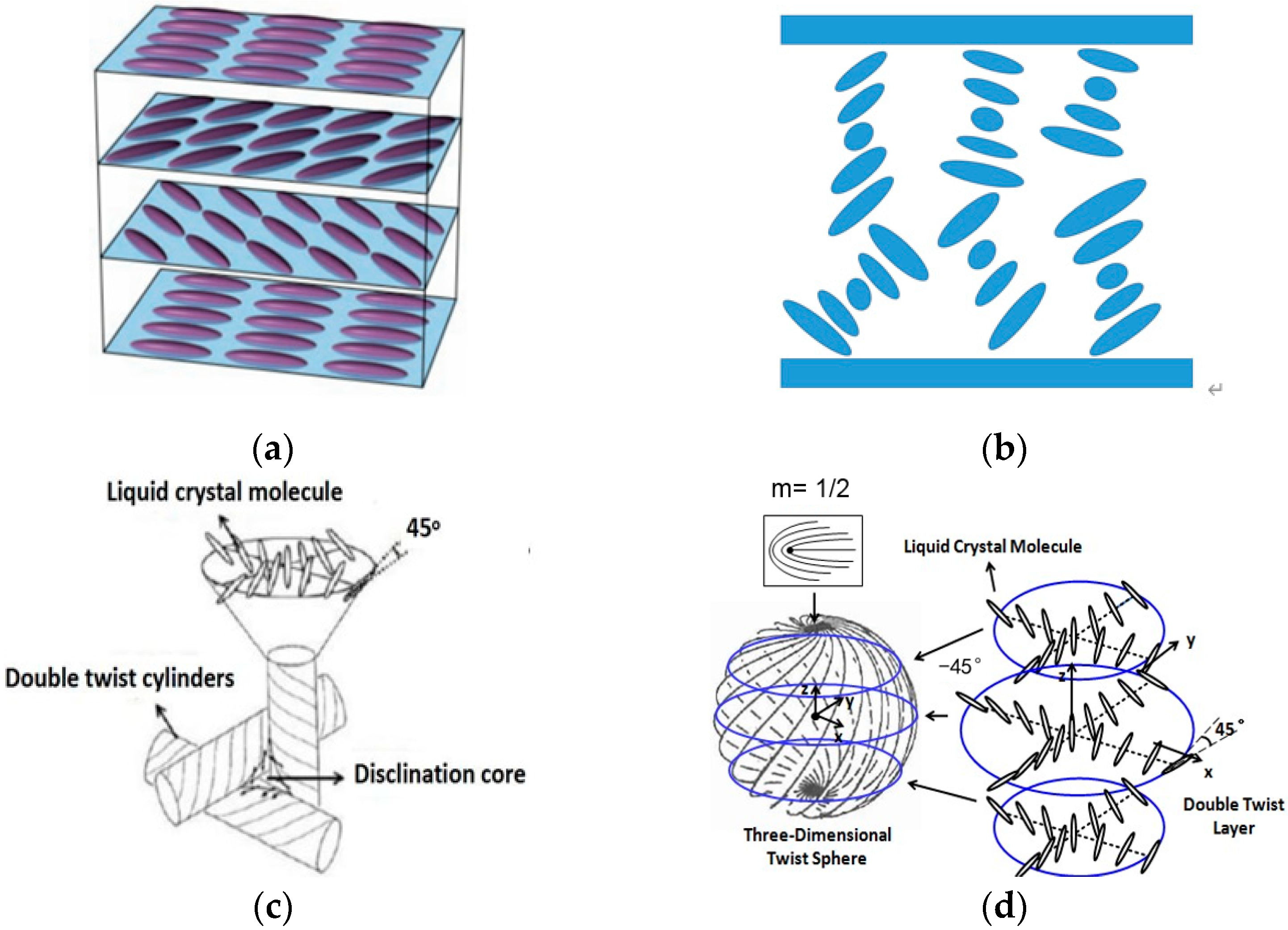
Twist structure liquid crystals (LCs) include cholesteric liquid crystals (CLCs) with one-dimensional twist structures, blue-phase liquid crystals (BPLCs) consisting of double twist cylinders (DTCs) and disclination lines, and sphere-phase liquid crystals (SPLCs) composed of three-dimensional twist structures (3-DTSs) and disclination lines. The structures of LC molecule arrangements in CLCs, BPLCs, and SPLCs are shown in Figure 1. The arrangements of LC molecules in CLCs consist of planar and focal conic states, which are shown in Figure 1a,b. Figure 1c,d shows arrangements of LC molecules in BPLCs and SPLCs, respectively. CLCs have attracted great attention in the field of optical filters due to their self-assembly structure and Bragg reflection [1,2,3,4]. BPLCs represent LC states with a regular array of DTCs and disclination lines among them existing in a narrow temperature range between the isotropic phase and cholesteric phase [5,6]. By polymer network, the thermal stability problem of BPLCs has been solved [7], which is desirable for potential applications in field sequential displays [8,9], three-dimensional (3-D) tunable photonic crystals [10,11], and phase modulator devices [12], owing to their interesting features, including sub-millisecond response times, optically isotropic dark states, alignment free, and periodic 3-D helical structures on the order of the visible wavelength [13]. SPLCs are usually observed in a narrow temperature range between the isotropic phase and cholesteric phase, or between the isotropic phase and blue phase due to their weak thermal stability, which is similar to that of BPLCs [14,15,16,17]. However, in contrast to BPLCs, SPLCs show optical anisotropic status. Because of the fast switching with low electric field, SPLCs show great potential for applications in lasing, light shutters, and tunable filters after the thermal stability problem is solved by a polymer stabilizing process.
Currently, several research studies have been proposed for a template technology with wash-out refilling, which has been used to reconstruct CLCs, BPLCs, and SPLCs. [18,19,20]. By refilling the nematic LC (NLC) into the polymer template, a twist structure LC can be achieved. In this paper, the template effects on the stability of twist structure LCs were investigated and the reconstructing capability of the CLC, BPLC, and SPLC template was illustrated. The multi-phase and multi-pitch twist structure LCs can be obtained with a polymer template, which provides for potential applications in optical communication, displays, and LC lasing. In particular, the multi-pitch LC with different wavelengths in the visible range can be used to form a good white light source for display applications. Additionally, with the multi-phase LCs, the potential to achieve hybrid lasing composed of normal lasing and random lasing has attracted significant attention.
2. Materials and Device Fabrication
Three kinds of material systems were prepared for the purpose of obtaining CLCs, BPLCs, and SPLCs. The polymer-stabilized CLC (PS-CLC) precursor was composed of a positive NLC (BPH006, Jiangsu Hecheng Display Technology Co., Ltd. (HCCH), Nanjing, Jiangsu, China), a chiral dopant (R5011, HCCH), an ultraviolet (UV) curable monomer (12A, HCCH), a cross-linker agent (C3M, HCCH), and a photo-initiator (IRG184, HCCH). The polymer-stabilized BPLC (PS-BPLC) precursor was composed of a positive NLC (HBG98, HCCH), a chiral dopant (R5011), a UV curable monomer (TMPTA), a cross-linking agent (C3M), and a photo-initiator (IRG184). The polymer-stabilized (PS-SPLC) precursor was composed of a positive nematic liquid crystal (SP001, Δn = 0.148, Δε = 33.2, HCCH), a chiral dopant (R5011), a UV curable monomer (12A), a cross-linking agent (C3M), and a photo-initiator (IRG184), as listed in Table 1.
The homogenous PS-CLC, PS-BPLC, and-PS-SPLC precursors were capillary filled into empty cells of 10 μm thickness and 25 mm × 20 mm area composed of 2 indium-tin-oxide glass substrates with antiparallel polyimide alignment layers in the isotropic phase, respectively. Then, they were cooled down at a rate of 0.5 °C/min using the temperature controller (HCS302, Intec, Boulder, CO, USA). During the cooling process, the phase-transition process and the platelet textures of these mixtures were observed under a polarized optical microscope (POM, XPL-30TF, Shanghai WeiTu Optics & Electron Technology Co., Ltd., Shanghai, China). The phase transition temperature of the PS-CLC precursor, from isotropic phase to cholesteric phase, was 61.9 °C, which is shown in Figure 2 depicting the phase transition process. The phase transition process of the PS-BPLC precursor is shown as follows: isotropic phase (55 °C); blue phase (48 °C); and cholesteric phase; the textures of the different phases are shown in Figure 3. The PS-SPLC precursor showed the following phase sequence: isotropic phase (45.5 °C); sphere phase (39 °C); and cholesteric phase, as shown in Figure 4.
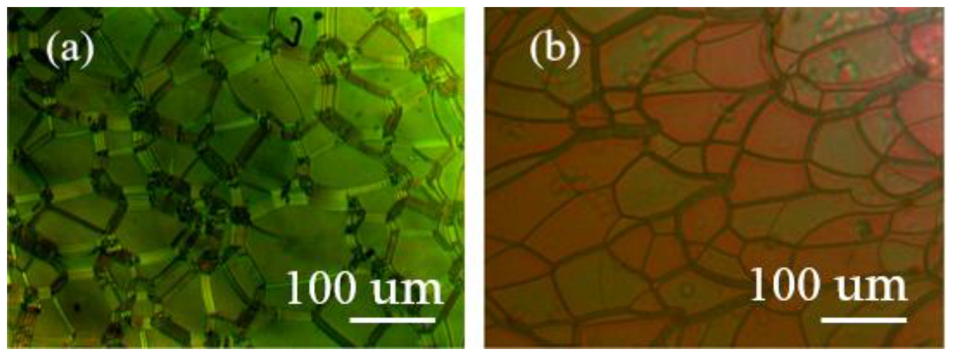
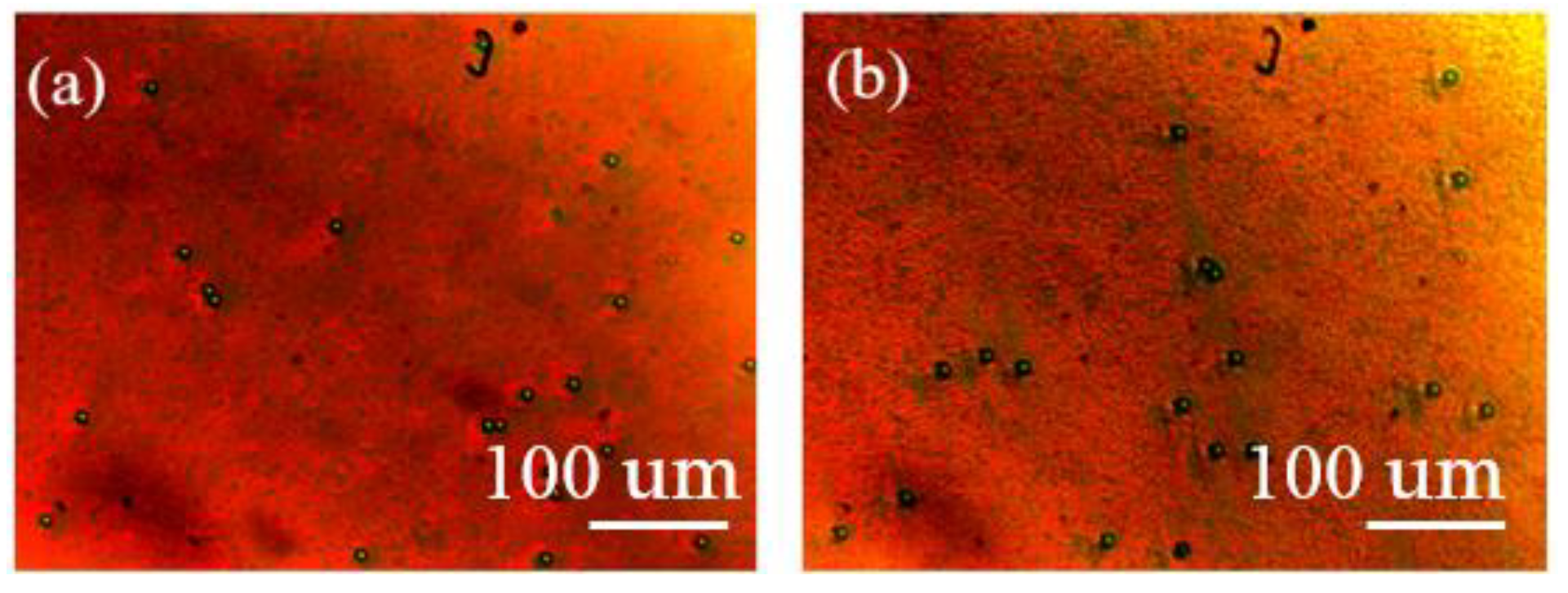
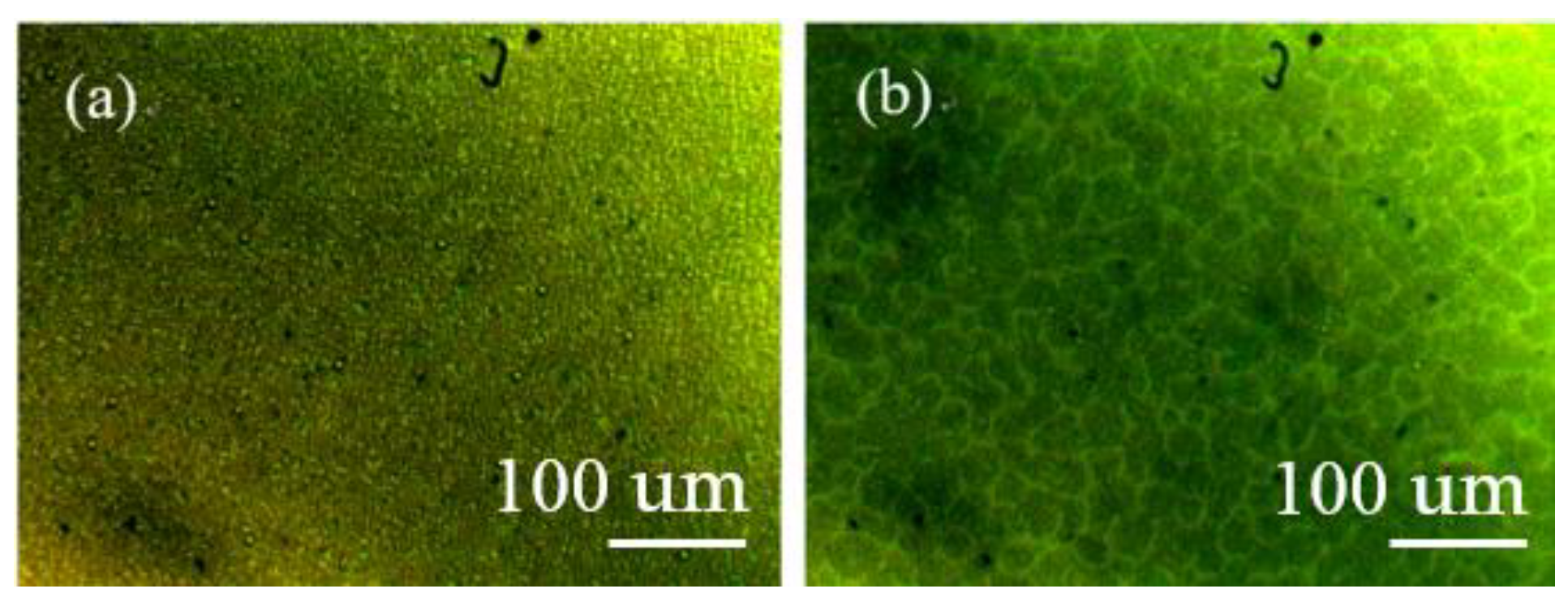
The polymer templates of CLCs, BPLCs, and SPLCs were obtained by performing the following procedures. First, in order to obtain a relatively high reflective wavelength, the PS-CLC, PS-BPLC, and PS-SPLC precursors were cooled down from the isotropic phase to 30 °C, 54 °C, and 44 °C, respectively, at a rate of 0.5 °C /min in the temperature controller. Then, the PS-CLC, PS-BPLC, and PS-SPLC samples were obtained by polymerizing these precursors under UV light (λ = 365 nm) with an intensity of 3.0 mw/cm−2 for 15 min. The platelet textures of the PS-CLCs, PS-BPLCs, and PS-SPLC, are shown in Figure 5a, Figure 6a, and Figure 7a, respectively. After cooling down to room temperature, the PS-CLC, PS-BPLC, and PS-SPLC cells composed of 2 indium-tin-oxide glass substrates were immersed in acetone for about 48 h, which washed away the unpolymerized components composed of LC, chiral dopant, unreacted monomers, and photo-initiator. Because 2 glass substrates were not separated, the washing rate was not high. Therefore, an acetone soaking time of 48 h was required. Finally, after evaporating the acetone at 80 °C on the temperature controller, the CLC, BPLC, and SPLC templates were obtained. To verify the reconstruction capability of the CLC template, an NLC, BPH006, was refilled into the CLC template at room temperature, and the cholesteric texture of templated-CLC (T-CLC) could be observed, as shown in Figure 5b. To verify the reconstruction capability of the BPLC template, an NLC, HBG98, was refilled into the BPLC template at room temperature, and the blue-phase texture of templated-BPLC (T-BPLC) could be observed, as shown in Figure 6b. To verify the reconstruction capability of the SPLC template, an NLC, SP001, was refilled into the SPLC template at room temperature, and the sphere phase texture of templated-SPLC (T-SPLC) could be observed, as shown in Figure 7b. The CLC, BPLC, and SPLC templates showed good reconstruction capability. Although we used cells composed of 2 glass substrates in the experiment, the CLCs, BPLCs, and SPLCs reconstructed by the wash-out refilling method can also be obtained with a single-glass substrate. Therefore, this wash-out refilling method also applies to large devices such as displays.
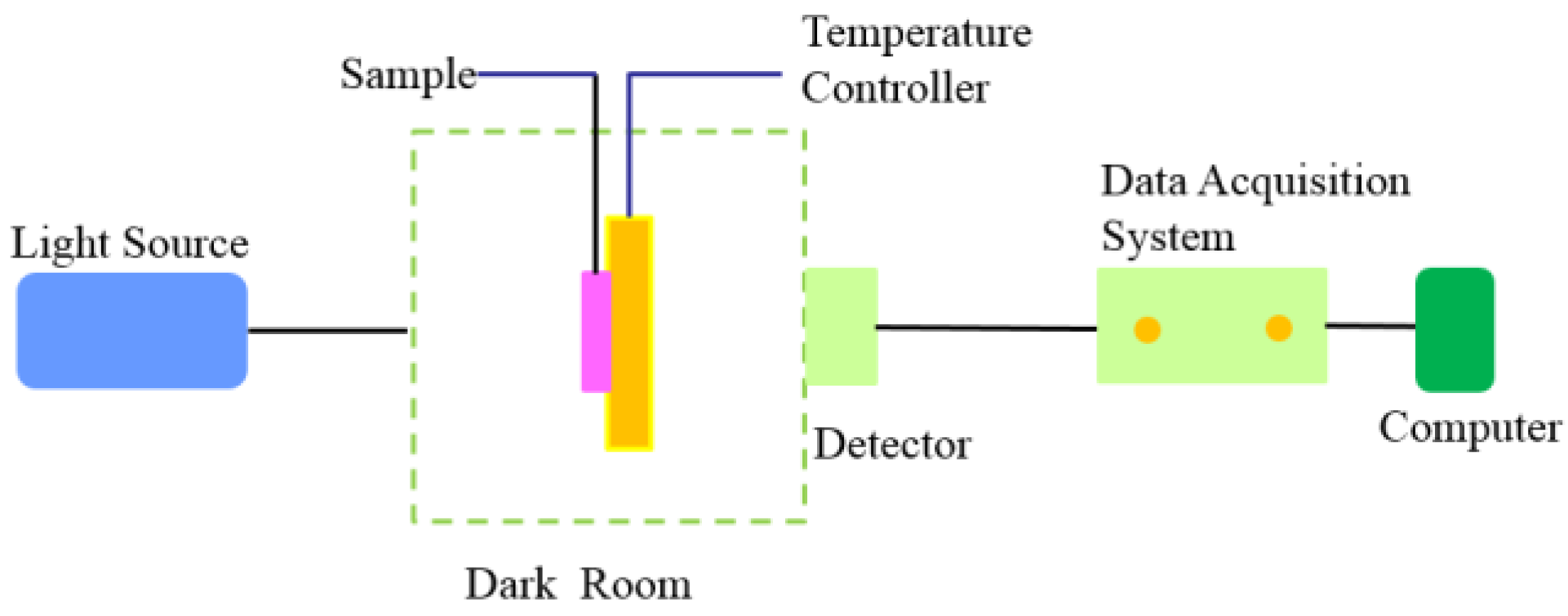
As shown in Figure 8, the measurement system was equipped to obtain the Bragg reflection spectra in the templating process. A tungsten bromine lamp provided the unpolarized light source with whole visible light spectrum. All the Bragg reflection spectra from the samples were collected by a detector connected to a data acquisition system (DCS300PA, Zolix, Beijing, China).
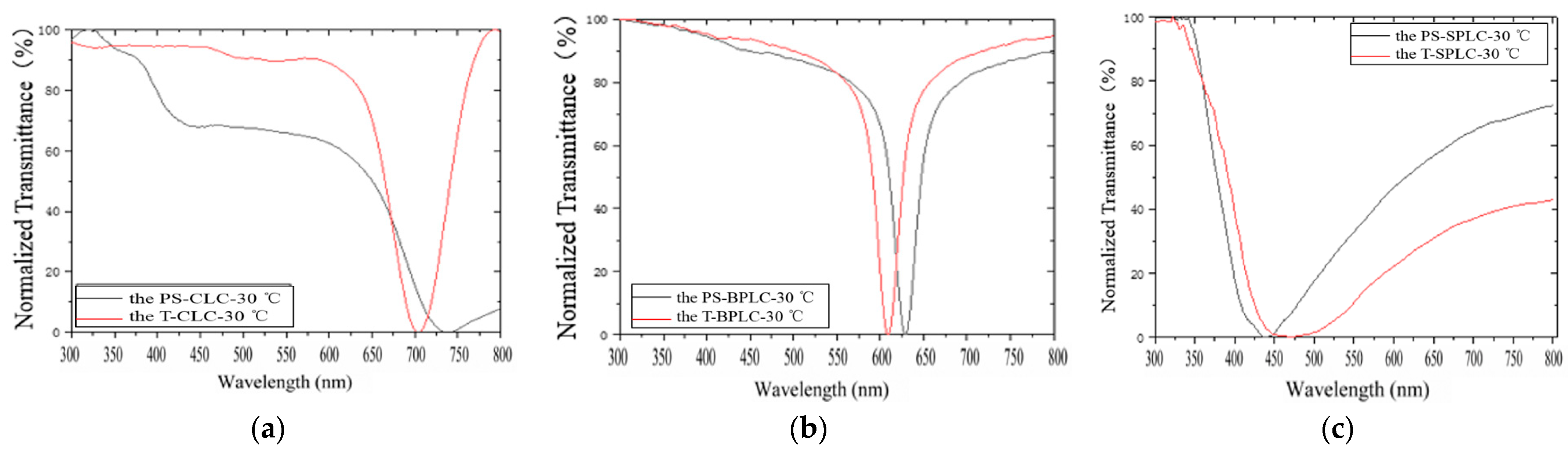
The reflection central wavelengths of PS-CLC and T-CLC were 740 nm and 704 nm, respectively, as shown in Figure 9a. The reflection spectrum of the PS-CLC is depicted by a black line, and the reflection spectrum of T-CLC, by a red line. The reflection central wavelengths of PS-BPLC and T-BPLC were 628 nm and 608 nm, respectively, as observed in the reflection spectra of PS-BPLC and T-BPLC in Figure 9b. The reflection central wavelengths of PS-SPLC and T-SPLC were 440 nm and 472 nm, respectively, as observed in the reflection spectra of PS-SPLC and T-SPLC in Figure 9c. After the templating process, the reflection central wavelength shifts of CLC, BPLC, and SPLC were very small. This demonstrated that the CLC, BPLC and SPLC can be reconstructed well by the templating process.
The twist structure LCs were refilled into the CLC, BPLC, and SPLC templates to investigate the template effect on the feasibility of multi-phase twist structure LCs.
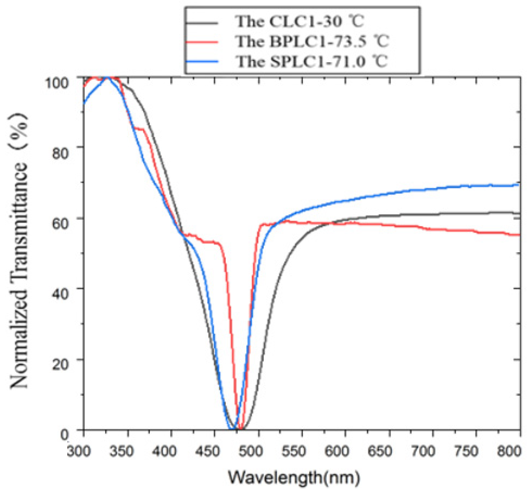
Because both the intrinsic T-CLC and T-BPLC had relatively long pitch, the CLC and BPLC templates were refilled with a short-pitch twist structure LC so that the reflection peaks of the refilling LC and template itself could be distinguished well. We prepared CLC1, BPLC1, and SPLC1, which were composed of NLC and chiral molecules, as listed in Table 2. The CLC1 was composed of 97.7 wt% HBG98 and 2.3 wt% R5011. The BPLC1 was composed of 96.2 wt% HBG98 and 3.8 wt% R5011. The SPLC1 was composed of 96.7 wt% SP001 and 3.3 wt% R5011. As shown in Figure 10, the reflection central wavelengths (λM) of CLC1, BPLC1, and SPLC1 were 478 nm, 478 nm, and 472 nm, respectively. The clearing points (Tc) of CLC1, BPLC1, and SPLC1 were respectively 75.5 °C, 74.5 °C, and 71.8 °C, as listed in Table 2.
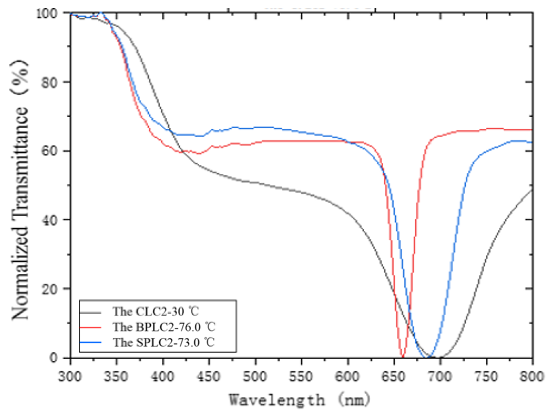
Because the intrinsic T-SPLC had relatively short pitch, the SPLC template was refilled with a long-pitch twist structure LC so that the reflection peaks of the refilling LC and template itself could be distinguished well. We prepared CLC2, BPLC2, and SPLC2, which were composed of NLC and chiral molecules, as listed in Table 3. The CLC2 was composed of 98.5 wt% HBG98 and 1.5 wt% R5011. The BPLC2 was composed of 97.2 wt% HBG98 and 2.8 wt% R5011. The SPLC2 was composed of 97.6 wt% SP001 and 2.4 wt% R5011. As shown in Figure 11, the reflection central wavelengths (λM) of CLC2, BPLC2, and SPLC2 were 700 nm, 660 nm, and 684 nm, respectively. The clearing points (Tc) of CLC2, BPLC2, and SPLC2 were respectively 79.5 °C, 77.0 °C, and 74.0 °C, as listed in Table 3.
3. Results and Discussion
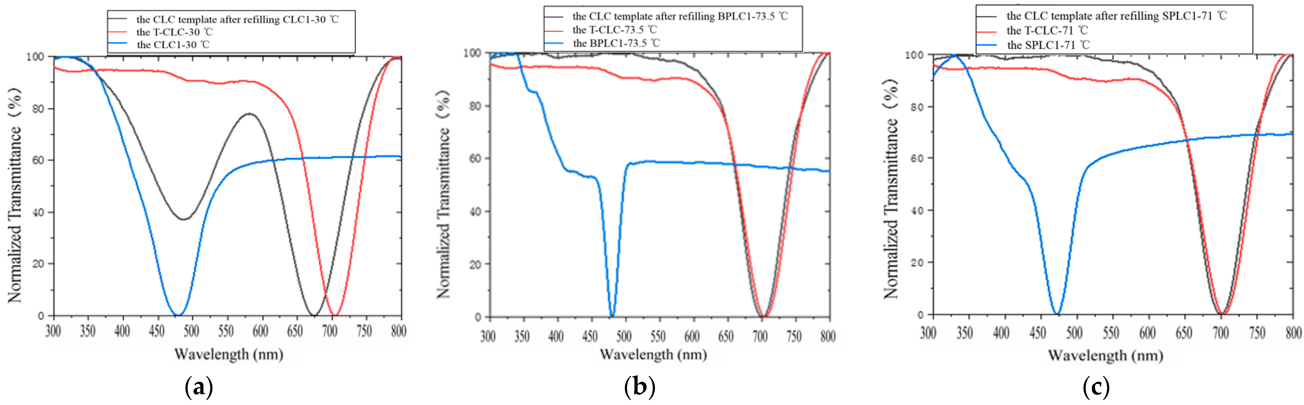
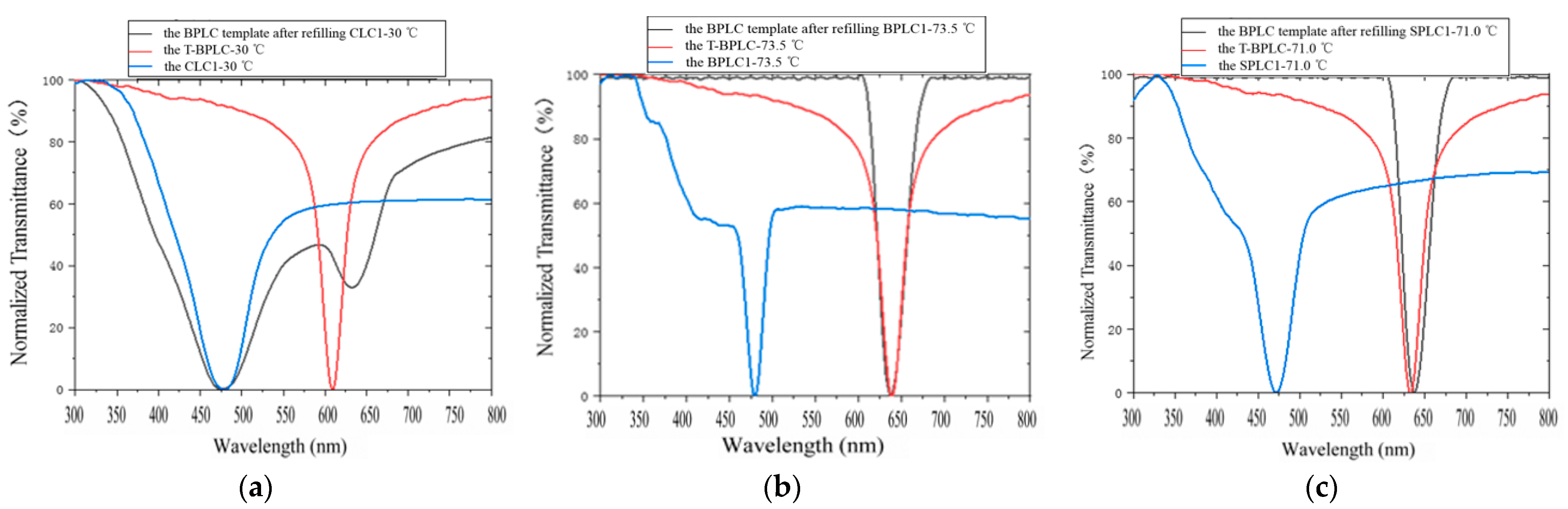
By filling the CLC template with the CLC1 at 80 °C and cooling down to 30.0 °C at a rate of 0.5 °C/min, two reflection peaks (black line) could be observed, as shown in Figure 12a. One was at approx. 674 nm, which is close to the reflection peak of the intrinsic T-CLC, and another was at approx. 484 nm, which is similar to the reflection peak of CLC1. This demonstrated that if the CLC template was refilled with a CLC of different pitch, both the refilled CLC and the intrinsic T-CLC could exist in the template. After the CLC templating process, only the one-dimensional twist structure was reconstructed, while the thermal stability of T-CLC was not improved due to a lack of defects in the lattice molecules of CLC. This means the thermal stability and free energy of CLC are similar to that of T-CLC. Therefore, a single-layer CLC film of multi-pitch can be fabricated by the templating process.
The CLC template was refilled with the BPLC1 at 80 °C and cooled down at a rate of 0.5 °C /min to 73.5 °C.The reflection spectrum of the CLC template with the refilling BPLC1 (black line) is shown in Figure 12b. Only a reflection peak of 700 nm was observed, which is close to the reflection peak of the intrinsic T-CLC. This means that only the intrinsic T-CLC but not refilled BPLC may exist in the template because the thermal stability of the BPLC is much weaker than that of T-CLC, and the free energy of BPLC is much higher than that of T-CLC; hence, the template can only reconstruct the intrinsic T-CLC.
The CLC template was refilled with the SPLC1 at 80 °C and cooled down at a rate of 0.5 °C /min to 71.0 °C.The reflection spectrum of the CLC template with the refilling SPLC1 (black line) is shown in Figure 12c. Only a reflection peak of 702 nm, which is close to the reflection peak of the intrinsic T-CLC, was observed. This means that only the intrinsic T-CLC but not refilled SPLC may exist in the template because the thermal stability of SPLC is much weaker than that of T-CLC, and the free energy of SPLC is much higher than that of T-CLC, only the intrinsic T-CLC was reconstructed in the template.
After refilling the CLC1 into the BPLC template at 80 ℃ and cooling down to 30 °C at a rate of 0.5 °C/min, two reflection peaks (black line) could be observed, as shown in Figure 13a. One was at approx. 632 nm, which is close to the reflection peak of the intrinsic T-BPLC, and the other was at approx 478 nm, which is the same as the reflection peak of the CLC1. This means that if the BPLC template was refilled with a CLC of different pitch, both the refilling CLC and intrinsic T-BPLC could exist. Because the position of the disclination lines among the DTCs was occupied by the polymer network, the BPLC template not only reconstructed the DTCs but also improved the stability of BPLC. Therefore, multi-phase and multi-pitch twist structure LC devices can be fabricated by the templating process, as the thermal stability of CLC is on the same level as that of T-BPLC.
The BPLC template was refilled with the BPLC1 at 80 °C and cooled down at a rate of 0.5 °C/min to 73.5 °C. The reflection spectrum of the BPLC template with the refilling BPLC1 (black line) is shown in Figure 13b. Only a reflection peak of 638 nm, which is the same as the reflection peak of the intrinsic T-BPLC, was observed. This means that only the intrinsic T-BPLC but not refilled BPLC may exist in the template because the thermal stability of BPLC is much weaker than that of T-BPLC, and the free energy of BPLC is much higher than that of T-BPLC; hence, only the intrinsic T-BPLC was reconstructed in the template.
The BPLC template was refilled with the SPLC1 at 80 °C and cooled down at a rate of 0.5 °C/min to 71.0 °C. The reflection spectrum of the BPLC template with the refilling SPLC1 (black line) is shown in Figure 13c. Only a reflection peak of 638 nm, which is close to the reflection peak of the intrinsic T-BPLC, was observed. This means that only the intrinsic T-BPLC but not refilled SPLC may exist in the template because the thermal stability of SPLC is much weaker than that of T-BPLC, and the free energy of SPLC is much higher than that of T-BPLC; hence, only the intrinsic T-BPLC was reconstructed in the template.
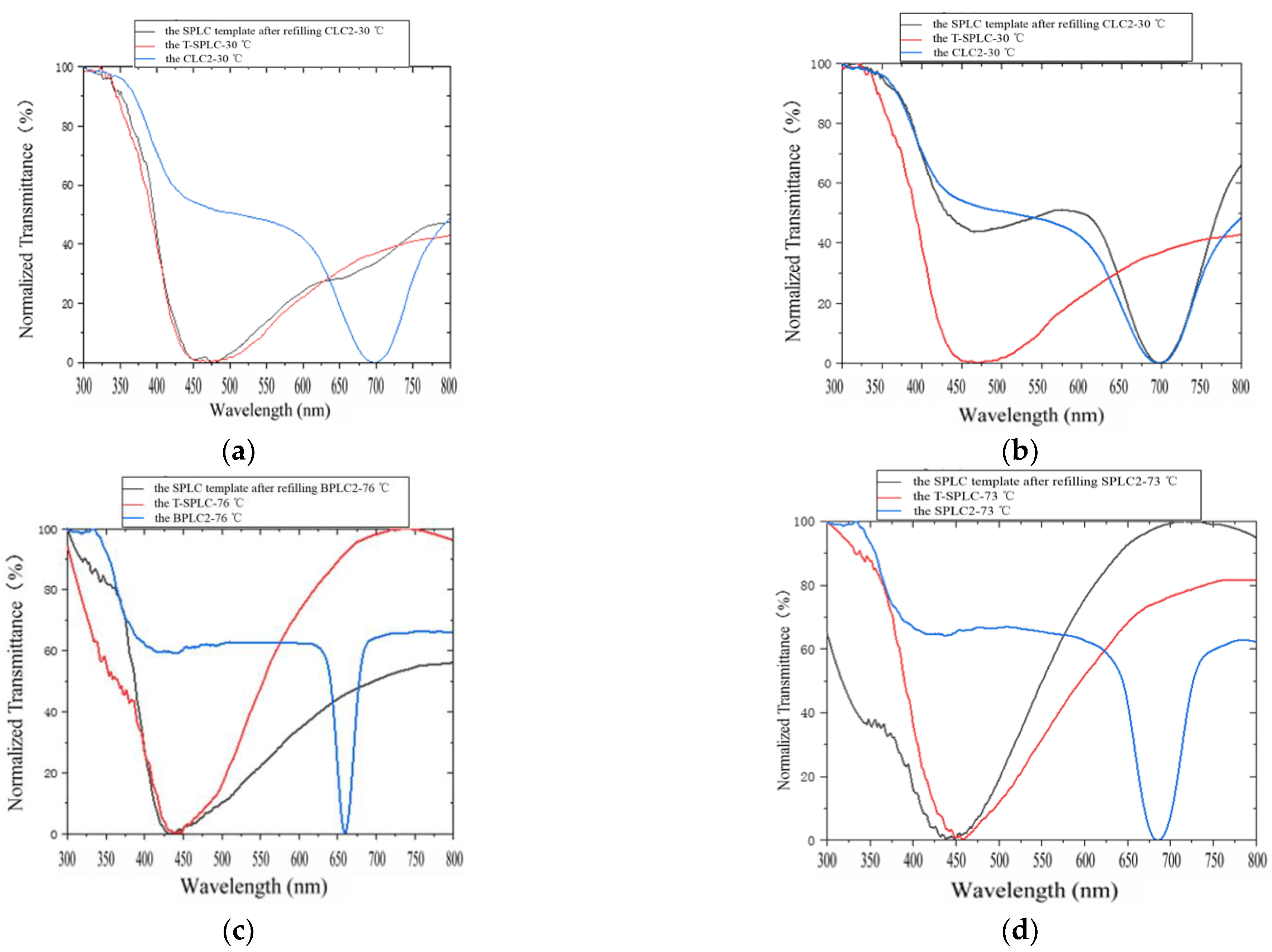
After refilling the CLC2 into the SPLC template at 80 °C, and cooling down to 30 °C at a rate of 0.5 °C/min, the reflection spectrum of SPLC template with the refilling CLC2 (black line) was obtained, as shown in Figure 14a. Only a reflection peak of 470 nm was observed, which is close to the reflection peak of the intrinsic T-SPLC. This means that only the intrinsic T-SPLC but not refilled CLC may exist in the template.
However, when the CLC2 was directly refilled into the SPLC template at 30 °C, two reflection peaks (black line) could be observed, as shown in Figure 14b. One was at approx. 468 nm, which is close to the reflection peak of the intrinsic T-SPLC, and another was at approx. 700 nm which is similar to the reflection peak of CLC2. This means that if a CLC of different pitch was directly refilled into the SPLC template at room temperature, both the refilling CLC and the intrinsic T-SPLC could co-exist.Therefore, multi-phase and multi-pitch twist structure LC devices can be fabricated.
CLC was refilled into the SPLC template at 30 °C, and also refilled into the SPLC template in the isotropic phase, then cooled down to 30 °C. The measured reflection spectra showed different results. The reason is that although through the templating process, the thermal stability and free energy of T-SPLC are similar to those of CLC, compared to the CLC and BPLC templates, in addition to reconstructing the intrinsic T-SPLC, the SPLC template can also reconstruct the initial state of the refilling twist structure LC. For example, when a CLC was refilled into the SPLC template at room temperature, the SPLC template could reconstruct the original cholesteric phase of the refilling CLC. However when a CLC was refilled into the SPLC template in the isotropic phase and then was cooled down to 30 °C, the SPLC template could reconstruct the original isotropic state of the refilling CLC. Therefore, temperature has little effect on multi-pitch and multi-phase structures in other phase state templates except for the SPLC template.
The SPLC template was refilled with the BPLC2 at 80 °C and cooled down at a rate of 0.5 °C/min to 76.0 °C. The reflection spectrum of the SPLC template with the refilling BPLC2 (black line) is shown in Figure 14c. Only a reflection peak of 434 nm was observed, which is the same as the reflection peak of the intrinsic T-SPLC. This means that only the intrinsic T-SPLC but not refilled BPLC may exist in the template because the thermal stability of BPLC is much weaker than that of T-SPLC, and the free energy of BPLC is much higher than that of T-SPLC; hence, only the intrinsic T-SPLC was reconstructed in the template.
The SPLC template was refilled with the SPLC2 at 80 °C, then it was cooled down at a rate of 0.5 °C/min to 73.0 °C. The reflection spectrum of the SPLC template with the refilling SPLC2 (black line) is shown in Figure 14d. Only a reflection peak of 444 nm was observed, which is close to the reflection peak of the intrinsic T-SPLC. This means that only the intrinsic T-SPLC but not refilled SPLC may exist in the template because the thermal stability of SPLC is much weaker than that of T-SPLC, and the free energy of SPLC is much higher than that of T-SPLC; hence, only the intrinsic T-SPLC was reconstructed in the template.
4. Conclusions
The CLC, BPLC, and SPLC could be reconstructed by the templating process. If a CLC of different pitch was refilled into the BPLC template in the isotropic phase, a multi-phase and multi-pitch twist structure LC that included both the refilling CLC and intrinsic BPLC appeared. However, if a BPLC or SPLC of different pitch was refilled into the BPLC template, only the intrinsic BPLC appeared. Additionally, for the SPLC template, if a CLC of different pitch was refilled into it in the isotropic phase, only the intrinsic SPLC appeared. However, if a CLC of different pitch was directly refilled into it at room temperature, a multi-phase and multi-pitch twist structure LC that included both the refilling CLC and intrinsic SPLC appeared. In addition, if a BPLC or SPLC of different pitch was refilled into an SPLC template, only the intrinsic SPLC appeared. If a CLC of different pitch was refilled into the CLC template, a multi-pitch twist structure LC that included the refilling CLC and intrinsic CLC appeared. However, if a BPLC or SPLC of different pitch was refilled into the CLC template, only the intrinsic CLC appeared. Therefore, the CLC and T-CLC, T-BPLC, and T-SPLC all showed thermal stability of the same level. Multi-phase and multi-pitch twist structure LC devices fabricated by the templating process show great potential for applications in optical communication, displays, and LC lasing.
Author Contributions
Writing—original draft preparation, Y.G.; writing—review and editing, T.H. and J.L. All authors have read and agreed to the published version of the manuscript.
Funding
This research was funded by National Natural Science Foundation of China, grant numbers 61727808 and 61775135.
Conflicts of Interest
The authors declare no conflict of interest.
References
- Mitov, M. Cholesteric liquid crystals with a broad light reflection band. Adv. Mater. 2012, 24, 6260–6276. [Google Scholar] [CrossRef] [PubMed]
- Huang, Y.; Jin, M.; Zhang, S. Polarization-independent bandwidth-variable tunable optical filter based on cholesteric liquid crystals. Jpn. J. Appl. Phys. 2014, 53, 072601. [Google Scholar] [CrossRef]
- Jeong, M.Y.; Mang, J.Y. Continuously tunable optical notch filter and band-pass filter systems that cover the visible to near-infrared spectral ranges. Appl. Opt. 2018, 57, 1962–1966. [Google Scholar] [CrossRef] [PubMed]
- Jeong, M.Y.; Kwak, K. Continuously Tunable and Bandwidth Variable Optical Notch/Band-Pass Filter Over 500 nm Spectral Range Using Cholesteric Liquid Crystals. IEEE Photonics J. 2019, 11, 1–11. [Google Scholar]
- Haseba, Y.; Kikuchi, H. Optically isotropic chiral liquid crystals induced by polymer network and their electro-optical behavior. Mol. Cryst. Liq. Cryst. 2007, 407, 1–9. [Google Scholar] [CrossRef]
- Zheng, Z.; Shen, D.; Huang, P. Wide blue phase range of chiral nematic liquid crystal doped with bent-shaped molecules. New J. Phys. 2010, 12, 113018. [Google Scholar] [CrossRef]
- Chen, K.M.; Gauza, S.; Xianyu, H.; Wu, S.T. Hysteresis effects in blue-phase liquid crystals. J. Disp. Technol. 2010, 6, 318–322. [Google Scholar] [CrossRef]
- Kim, M.; Kang, B.G.; Kim, M.S.; Kim, M.K.; Kumar, P.; Lee, M.H.; Kang, S.W.; Lee, S.H. Measurement of local retardation in optically isotropic liquid crystal device driven by in-plane electric field. Curr. Appl. Phys. 2010, 10, e118–e121. [Google Scholar] [CrossRef]
- Coles, H.; Morris, S. Liquid-crystal lasers. Nat. Photonics 2010, 4, 676–685. [Google Scholar] [CrossRef]
- Yokoyama, S.; Mashiko, S.; Kikuch, H.; Uchida, K.; Nagamura, T. Laser emission from a polymer-stabilized liquid-crystalline blue-phase. Adv. Mater. 2006, 18, 48–51. [Google Scholar] [CrossRef]
- Lu, S.Y.; Chien, L.C. Electrically switched color with polymer-stabilized blue-phase liquid crystals. Opt. Lett. 2010, 35, 562–564. [Google Scholar] [CrossRef] [PubMed]
- Yan, J.; Li, Y.; Wu, S.T. High-efficiency and fast-response tunable phase grating using a blue phase liquid crystal. Opt. Lett. 2011, 36, 1404–1406. [Google Scholar] [CrossRef] [PubMed]
- Lin, J.D.; Huang, S.Y.; Wang, H.S.; Lin, S.H.; Mo, T.S.; Horng, C.T.; Yeh, H.C.; Chen, L.J.; Lin, H.L.; Lee, C.R. Spatially tunable photonic bandgap of wide spectral range and lasing emission based on a blue phase wedge cell. Opt. Express 2014, 22, 29479–29492. [Google Scholar] [CrossRef] [PubMed]
- Zhu, J.L.; Ni, S.B.; Chen, C.P.; Wu, D.Q.; Song, X.L.; Chen, C.Y.; Lu, J.G.; Su, Y.; Shieh, H.P.D. Chiral-induced self-assembly sphere phase liquid crystal with fast switching time. Appl. Phys. Lett. 2014, 104, 091116. [Google Scholar] [CrossRef] [Green Version]
- Sun. C.; Lu, J. A Tunable NIR Filter with Sphere Phase Liquid Crystal. Crystals 2019, 9, 349. [Google Scholar] [CrossRef] [Green Version]
- Zhu, J.L.; Li, W.H.; Sun, Y.; Lu, J.G.; Song, X.L.; Chen, C.Y.; Zhang, Z.; Su, Y. Random laser emission in a sphere-phase liquid crystal. Appl. Phys. Lett. 2015, 106, 191903. [Google Scholar] [CrossRef]
- Gao, L.; Gao, Y.P.; Du, X.W.; Ye, W.J.; Xu, Q.; Zhu, J.L.; Han, W.M.; Chen, C.Y.; Sun, Y.B. Electro-optical performance of polymer-stabilized sphere phase liquid crystal displays. Opt. Express 2017, 25, 18009–18016. [Google Scholar] [CrossRef] [PubMed]
- Guo, J.; Wu, H.; Chen, E.; Zhang, L.; He, W.; Yang, H.; Wei, J. Fabrication of multi-pitched photonic structure in cholesteric liquid crystals based on a polymer template with helical structure. J. Mater. Chem. 2010, 20, 4094–4102. [Google Scholar] [CrossRef]
- Castles, F.; Days, F.V.; Morris, S.M.; Ko, D.H.; Gardiner, D.J.; Qasim, M.M.; Nosheen, S.; Hands, P.J.W.; Choi, S.S.; Friend, R.H.; et al. Blue-phase template fabrication of three-dimensional nanostructures for photonics applications. Nat. Mater. 2012, 11, 599–603. [Google Scholar] [CrossRef] [PubMed]
- Chen, Z.; Hu, D.; Chen, X.; Zeng, D.; Lee, Y.; Chen, X.; Lu, J. Templated sphere phase liquid crystals for tunable random lasing. Nanomaterials 2017, 7, 392. [Google Scholar] [CrossRef] [PubMed] [Green Version]
Figure 1.
The arrangements of LC molecules in (a) planar texture state CLC; (b) focal conic CLC; (c) BPLC; (d) SPLC.
Figure 1.
The arrangements of LC molecules in (a) planar texture state CLC; (b) focal conic CLC; (c) BPLC; (d) SPLC.

Figure 2.
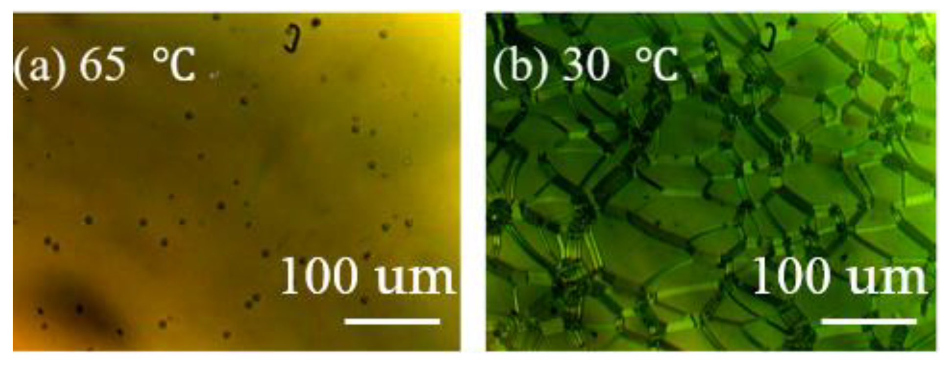
POM images of the PS-CLC precursor with: (a) isotropic phase (65 °C); (b) cholesteric phase (30 °C).
Figure 2.
POM images of the PS-CLC precursor with: (a) isotropic phase (65 °C); (b) cholesteric phase (30 °C).

Figure 3.
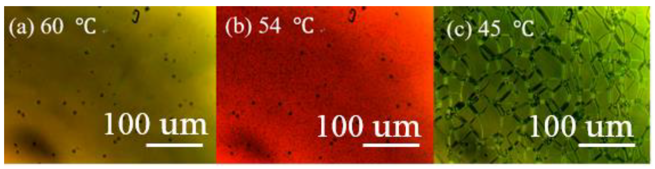
POM images of the PS-BPLC precursor with: (a) isotropic phase (60 °C); (b) blue phase (54 °C); (c) cholesteric phase (45 °C).
Figure 3.
POM images of the PS-BPLC precursor with: (a) isotropic phase (60 °C); (b) blue phase (54 °C); (c) cholesteric phase (45 °C).

Figure 4.
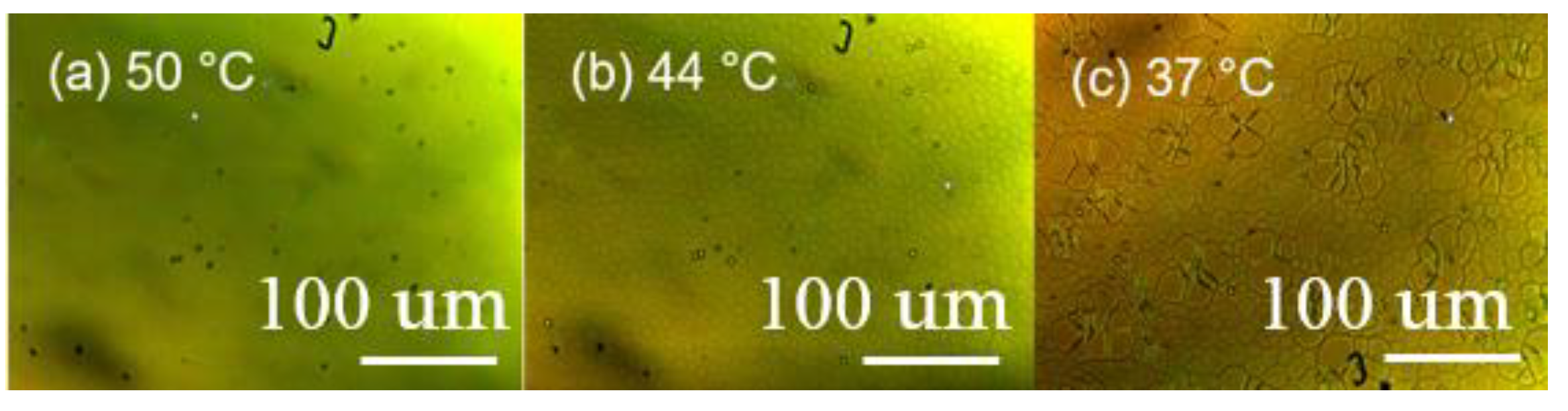
POM images of the PS-SPLC precursor with: (a) isotropic phase (50 °C); (b) sphere phase (44 °C); (c) cholesteric phase (37 °C).
Figure 4.
POM images of the PS-SPLC precursor with: (a) isotropic phase (50 °C); (b) sphere phase (44 °C); (c) cholesteric phase (37 °C).

Figure 5.
The surface morphology of (a) PS-CLC and (b) T-CLC.

Figure 6.
The surface morphology of (a) PS-BPLC and (b) T-BPLC.

Figure 7.
The surface morphology of (a) PS-SPLC and (b) T-SPLC.

Figure 8.
Schematic diagram of the transmittance measure system.

Figure 9.
The reflection spectra of (a) the PS-CLC and T-CLC; (b) PS-BPLC and T-BPLC; (c) PS-SPLC and T-SPLC.
Figure 9.
The reflection spectra of (a) the PS-CLC and T-CLC; (b) PS-BPLC and T-BPLC; (c) PS-SPLC and T-SPLC.

Figure 10.
The reflection spectra of CLC1, BPLC1, and SPLC1.

Figure 11.
The reflection spectra of CLC2, BPLC2, and SPLC2.

Figure 12.
The reflection spectra of (a) CLC1, T-CLC, and the CLC template after refilling CLC1; (b) BPLC1, T-CLC, and the CLC template after refilling BPLC1; (c) SPLC1, T-CLC, and the CLC template after refilling SPLC1.
Figure 12.
The reflection spectra of (a) CLC1, T-CLC, and the CLC template after refilling CLC1; (b) BPLC1, T-CLC, and the CLC template after refilling BPLC1; (c) SPLC1, T-CLC, and the CLC template after refilling SPLC1.

Figure 13.
The reflection spectra of (a) CLC1, T-BPLC, and the BPLC template after refilling CLC1; (b) BPLC1, T-BPLC, and the BPLC template after refilling BPLC1; (c) SPLC1, T-BPLC, and the BPLC template after refilling SPLC1.
Figure 13.
The reflection spectra of (a) CLC1, T-BPLC, and the BPLC template after refilling CLC1; (b) BPLC1, T-BPLC, and the BPLC template after refilling BPLC1; (c) SPLC1, T-BPLC, and the BPLC template after refilling SPLC1.

Figure 14.
The reflection spectra of (a) CLC2, T-SPLC, and the SPLC template after refilling CLC2; (b) CLC2, T-SPLC, and the CLC2 were directly refilled into the SPLC template at 30 °C; (c) BPLC2, T-SPLC, and the SPLC template after refilling BPLC2; (d) SPLC2, T-SPLC, and the SPLC template after refilling SPLC2.


Table 1.
The PS-CLC, PS-BPLC and PS-SPLC precursors of material system.
| BPH006/HBG98 /SP001 [wt%] | R5011 [wt%] | 12A [wt%] | TMPTA [wt%] | C3M [wt%] | IRG184 [wt%] | |
|---|---|---|---|---|---|---|
| PS-CLC | 86.40 | 1.50 | 6.00 | 6.00 | 0.10 | |
| PS-BPLC | 85.05 | 2.85 | 5.12 | 6.88 | 0.10 | |
| PS-SPLC | 79.45 | 3.45 | 8.50 | 8.50 | 0.10 |
Table 2.
Compositions, reflection central wavelengths, and clearing points of CLC1, BPLC1 and SPLC1.
Table 2.
Compositions, reflection central wavelengths, and clearing points of CLC1, BPLC1 and SPLC1.
| Mixture | Weight Ratio [wt%] | λM/nm | Tc/°C |
|---|---|---|---|
| CLC1 | HBG98(97.7)/R5011(2.3) | 478 | 75.5 |
| BPLC1 | HBG98(96.2)/R5011(3.8) | 478 | 74.5 |
| SPLC1 | SP001(96.7)/R5011(3.3) | 472 | 71.8 |
Table 3.
Compositions, reflection central wavelengths, and clearing points of CLC2, BPLC2, and SPLC2.
Table 3.
Compositions, reflection central wavelengths, and clearing points of CLC2, BPLC2, and SPLC2.
| Mixture | Weight Ratio [wt%] | λM/nm | Tc/°C |
|---|---|---|---|
| CLC2 | HBG98(98.5)/R5011(1.5) | 700 | 79.5 |
| BPLC2 | HBG98(97.2)/R5011(2.8) | 660 | 77.0 |
| SPLC2 | SP001(97.6)/R5011(2.4) | 684 | 74.0 |
Publisher’s Note: MDPI stays neutral with regard to jurisdictional claims in published maps and institutional affiliations. |
© 2021 by the authors. Licensee MDPI, Basel, Switzerland. This article is an open access article distributed under the terms and conditions of the Creative Commons Attribution (CC BY) license (https://creativecommons.org/licenses/by/4.0/).
Share and Cite
MDPI and ACS Style
Gao, Y.; Huang, T.; Lu, J. Template Effect of Multi-Phase Liquid Crystals. Crystals 2021, 11, 602. https://0-doi-org.brum.beds.ac.uk/10.3390/cryst11060602
AMA Style
Gao Y, Huang T, Lu J. Template Effect of Multi-Phase Liquid Crystals. Crystals. 2021; 11(6):602. https://0-doi-org.brum.beds.ac.uk/10.3390/cryst11060602
Chicago/Turabian StyleGao, Yao, Tengfei Huang, and Jiangang Lu. 2021. "Template Effect of Multi-Phase Liquid Crystals" Crystals 11, no. 6: 602. https://0-doi-org.brum.beds.ac.uk/10.3390/cryst11060602
Note that from the first issue of 2016, this journal uses article numbers instead of page numbers. See further details here.