Article

Combined Effect of Multi-Walled Carbon Nanotubes, Steel Fibre and Glass Fibre Mesh on Novel Two-Stage Expanded Clay Aggregate Concrete against Impact Loading

1
School of Civil Engineering, SASTRA Deemed University, Thanjavur 613401, India
2
Civil Engineering Department, Wasit University, Kut 52003, Iraq
3
Department of Civil Engineering, College of Engineering, Prince Sattam Bin Abdulaziz University, Alkharj 16273, Saudi Arabia
4
Department of Civil Engineering, Faculty of Engineering, Amran University and IT, Quhal 9677, Yemen
5
School of Engineering, Far Eastern Federal University, 8, Sukhanova Str., 690950 Vladivostok, Russia
6
Institute of Civil Engineering, Peter the Great St. Petersburg Polytechnic University, 195251 St. Petersburg, Russia
7
Department of Machinery Parts and Theory of Mechanisms, Moscow Automobile and Road Construction University, 125319 Moscow, Russia
*
Author to whom correspondence should be addressed.
Submission received: 14 May 2021 / Revised: 31 May 2021 / Accepted: 8 June 2021 / Published: 23 June 2021

Abstract

:
The use of expanded clay aggregate (ECA) for developing lightweight concrete results in strength-reduction properties. However, the ECA-based concrete strength properties can be improved by adding steel fibre (SF), glass fibre mesh (GFM) and multi-walled nano-carbon tubes (MWCNT). The combined effect of MWCNT, GFM, SF and ECA-based concrete and its strength properties is still unexplored. It is worth drawing a logical conclusion concerning the impact on the strength of concrete by incorporating the materials mentioned above. Two-stage expanded clay aggregate fibrous concrete (TECAFC) is a new concrete type and an emerging research area in material engineering. The casting method of TECAFC includes the two essential phases as follows. First, ECA and fibres are filled into the empty cylindrical mould to develop a natural skeleton. Second, the grout comprising cement, sand and MWCNT, are injected into the developed skeleton to fill voids. In this research, eight mixtures were prepared with 0.1 and 0.2% of MWCNT, 2.5% dosage of SF and three different layers of GFM inserted between the two layers of concrete. These eight mixtures were divided into two series of three mixtures each, in addition to two reference mixtures that include no SF or GFM. The first series of mixtures was comprised of 0.1% of MWCNT and 2.5% of SF and one, two and three layers of GFM insertion. The second series was the same as the first series and the dosage of MWCNT was taken as 0.2%. All cylindrical specimens were tested under drop mass impact as per the suggestions made by the ACI Committee 544. The test results showed that incorporating steel fibres and GFM improved the cracking and failure impact resistance by more than 270 and 1100%, respectively, and increased the impact ductility index by more than 220%, significantly contributing to steel fibres.

1. Introduction

Due to the paucity of available energy supplies, many studies are currently underway to utilise energy-efficient and energy conservation materials. In today’s globalised world, the construction industry is a fast-growing industry due to the enormous demands of current infrastructure. In this situation, ecological balance and energy-efficient buildings make it possible to increase efficiency through enhancing thermal properties and using lightweight building materials. In such a situation, lightweight concrete in the building sector became common with two main benefits: fewer transportation costs and lessened weight of the structure. The density of lightweight concrete varies between 1120 and 1920 kg/m3. Various techniques were used to produce this type of concrete, and previous investigations used an ECA for producing lightweight concrete and examined the strength properties. ECA production consists of special plastic clay with and without the addition of lime content. Dried clay is heated and burned at high temperatures of 1100–1300 °C [1]. During the heating process, the releasing of gas happens inside the pellets and is trapped during the cooling process, while burnt-off organic compounds makes the pellets bloated and create porous ceramic pellets, resulting in a lightweight material with high resistance to crushing [2]. The expansion of the ECA pellet occurs up to 5–6-fold by volume [3]. Priyanga et al. [4] reported that the concretes compressive strength is decreased up to 8.67, 17.92, 22.83 and 28% with 45, 50, 60 and 70% ECA used as a substitution of coarse aggregate, respectively. Scotta and Giorgi [5] studied the comparison of ECA (size of 0–15 mm)-based concrete and natural coarse aggregate concrete by incorporating a 0.4% dosage of SF. Results indicated that the modulus of elasticity and flexural strength of ECA-based concrete is decreased by about 24.86 and 47.9%, respectively. Bocca and Rossetti [6] reported that with 8–15 mm of ECA as a substitution of coarse aggregate in concrete, the compressive strength decreased by 39.82%. Khafaga [7] reported that the splitting tensile strength, compressive strength and modulus of elasticity of concrete comprising 50% ECA by volume were decreased by 22.25, 3.4 and 22.5%, respectively. Several investigations reported the compressive strength of ECA concrete, whereas the impact performance of ECA based concrete was not examined till now.
Two-stage concrete (TSC), also named preplaced aggregate concrete, is an individualistic tendency concrete category developed using a unique technique dissimilar to conventional plain concrete (PC). In PC, cement, fine and coarse aggregate are premixed before placing in the mould and then grout comprising sand, binder and water is injected into the mould. This makes the cement paste decrease in up to 50% of volume, therefore decreasing cement consumption and accompanying greenhouse gas emissions. Additionally, a procedure for consolidation such as vibration and compaction are not necessary to attain a dense and monolithic structure, which lessens labour intensity and the production of energy [8]. TSC has found widespread applications in recent years, including radiation-shielding structures, nuclear power station structures, tunnels with low shrinkage, mass concrete structures (ex., dams) and underwater constructions. Recently, a number of investigations have been conducted on the strength properties of TSC with and without fibres. Nehdi et al. [9] described that the tensile and compressive strength of TSC improved with adding a higher amount of SF. This improvement is due to the higher dosage (6% by volume) and length of SF. A higher dosage of SF caused great enhancement in flexural strength and exhibited exceptional post-crack behaviour. Murali and Ramprasad [10] developed the single- and multi-layered TSC slabs with different SF. The higher fibre dosage of 4% is provided at the top and bottom layer and 2% at the middle layer. The finding indicated that the three-layered TSC displayed a superior impact strength than single-layer TSC. Abirami et al. [11] stated that the impact resistance of TSC comprising 4 and 5% improved by 3134 and 3636%, respectively, as associated with reference TSC without fibre. Several materials have been used to improve the concrete strength, such as GFM, which provides more benefits, such as increased strength, excellent resistance to corrosion, low density, etc. For example, Abirami et al. [12] examined the impact behaviour of three-layered TSC cylindrical specimens comprising SF and GFM at various diameters and several layers. Results revealed that a GFM insertion of 150 mm in diameter and SF of 2.5% dosage improved the impact energy of the tested specimens. The combined effect of SF and GFM was very effective in resisting crack proliferation and delaying failure. Haridharan et al. [13] reported that the insertion of GFM and Textile fibre mesh in two-layered fibrous TSC resulted in a remarkable improvement in impact resistance, which absorbs more impact energy by SF and meshes, resulting in delayed failure. Murali et al. [14] stated that the GFM insertion between the three-layered TSC exhibited a 30% impact strength improvement than the reference TSC.
Recently, nanomaterials in the construction sector have evolved rapidly due to their improved mechanical properties and electrical and thermal properties. Incorporating MWCNT as a nano reinforcement in concrete is a growing trend in recent times. Li et al. [15] reported that the flexural and compressive strength of cement matrix composite comprising MWCNT after modified by using H2SO4 and HNO3 resulted in an increase of 25 and 19%, respectively. Al-Rub et al. [16] studied the strength properties of concrete comprised of short and long MWCNT. Findings indicated that 0.2% of short MWCNT showed a rising trend of flexural strength by 269%, whereas a 65% improvement in strength was observed in 0.1% of long MWCNT. Murali et al. [17] investigated the impact behaviour of fibrous TSC prepared using 100% of ECA, 2.5% of SF, 0.2% of MWCNT, and four layers of GFM had a diameter 50, 75, 100, 125 and 150 mm. Results revealed that the concrete compressive strength was increased by 67.5% by incorporating 0.2% MWCNT and 2.5% of SF, as associated with the reference concrete. The addition of 0.2% of MWCNT resulted in a substantial improvement in impact resistance by 28–66% in comparison with the reference specimen. The combined effect of MWCNT, SF and GFM exhibited an exceptional impact resistance.
Although several studies have been conducted to assess the impact strength of fibrous TSC with the addition of fibres, GFM and MWCNT independently, the combined effect of SF, GFM, ECA and MWCNT on the impact performance of TSC is minimal and needs special attention. This study aims to examine the impact behaviour of fibrous TECAFC comprised 2.5% of SF, 150 mm diameter GFM and 0.1 and 0.2% MWCNT.

2. Experimental Procedure
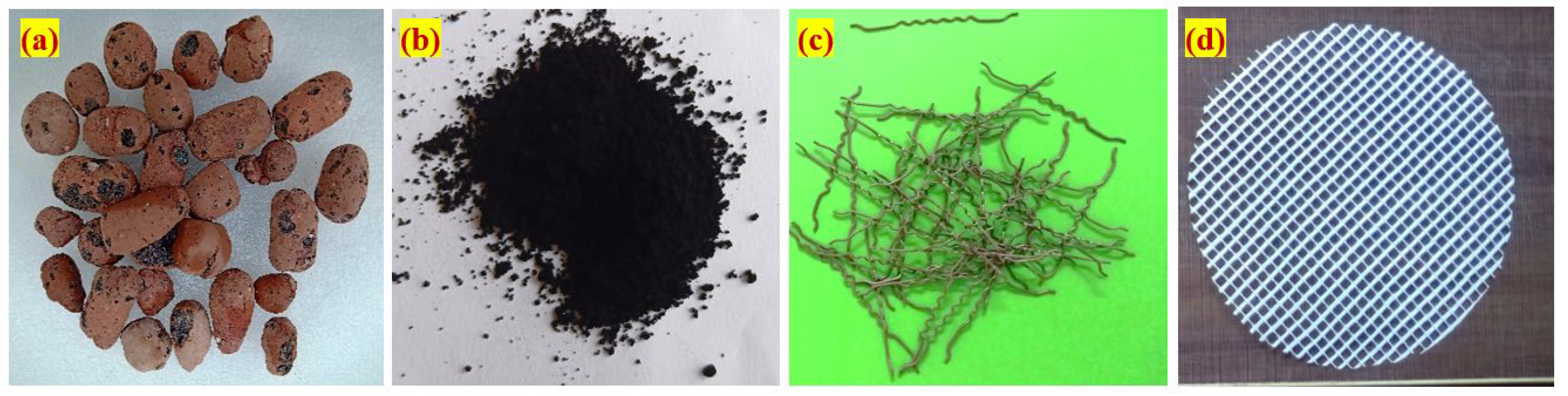
2.1. Raw Materials

  • Binder used in this investigation was Ordinary Portland Cement in accordance with IS: 12269-1987 [18]; the specific gravity of the binder was 3.14 and Blaine’s specific surface area was 318 m2/kg.
  • Local natural river sand of size less than 2.36 mm was utilised as fine aggregate in accordance with IS 383: 2002 [19]. The specific gravity and fineness modulus of the used fine aggregate were 2.41 and 2.65, respectively.
  • ECA was used as a coarse aggregate of size 12 ± 2 mm with a fineness modulus of 6.93, a loose bulk density of 310 kg/m3, water absorption of 17% and crushing strength of 1.12 N/mm2. The chemical properties of ECA were as follows; SiO2 of 48%, Al2O3 of 16.24%, Fe2O2 of 16.8%, CaO% of 0.42, MgO of 0.56%, K2O of 0.7%, Na2O of 1.1% and LOI of 16%. Figure 1a shows the appearance of used ECA.
  • MWCNT used in this research was procured from Ultra Nanotech Pvt Limited, Bengaluru, India. The dosage of MWCNT used was 0.1 and 0.2% by cement weight, and the selection of these dosages based on literature reported the maximum compressive strength achieved. Figure 1b shows the appearance of used MWCNT. The MWCNT had properties of 10–15 nm diameter, 2–10 µm length, 97% purity, <2% purity, <4000 mg/kg Fe, <3500 mg/kg Al, <800 mg/kg Mo, 250–270 m2/g specific surface area and 0.06–0.09 g/cm3 bulk density.
  • A new shape of steel fibre was used; the hybrid shape of crimped-hooked end fibre was 30 mm long, 0.5 mm diameter and 1200 MPa tensile strength. The fibre appearance is shown in Figure 1c.
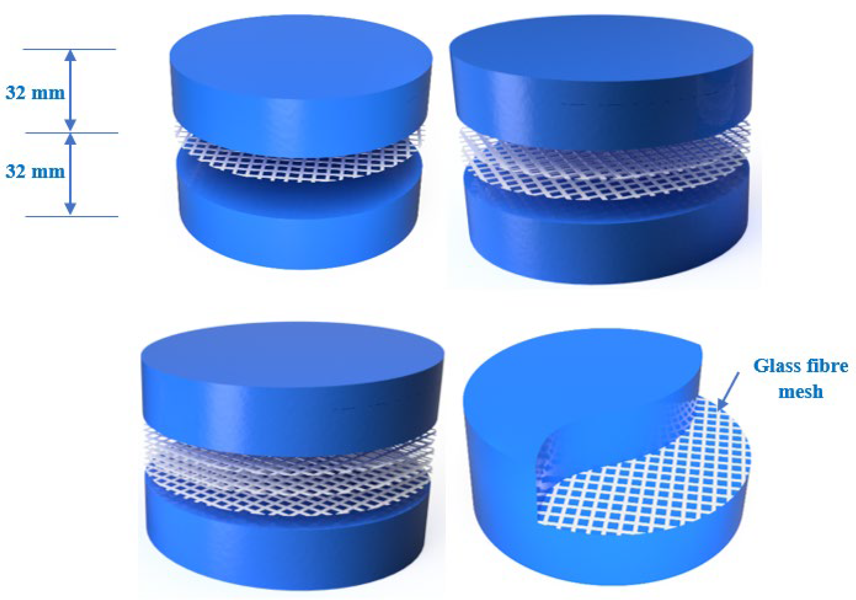
  • Figure 1d shows the 150 mm diameter GFM with 5 × 5 mm grid spacing and 1 mm thickness used. The tensile strength of GFM was 25 kN/m and the weight/unit area was 125 g/m2.
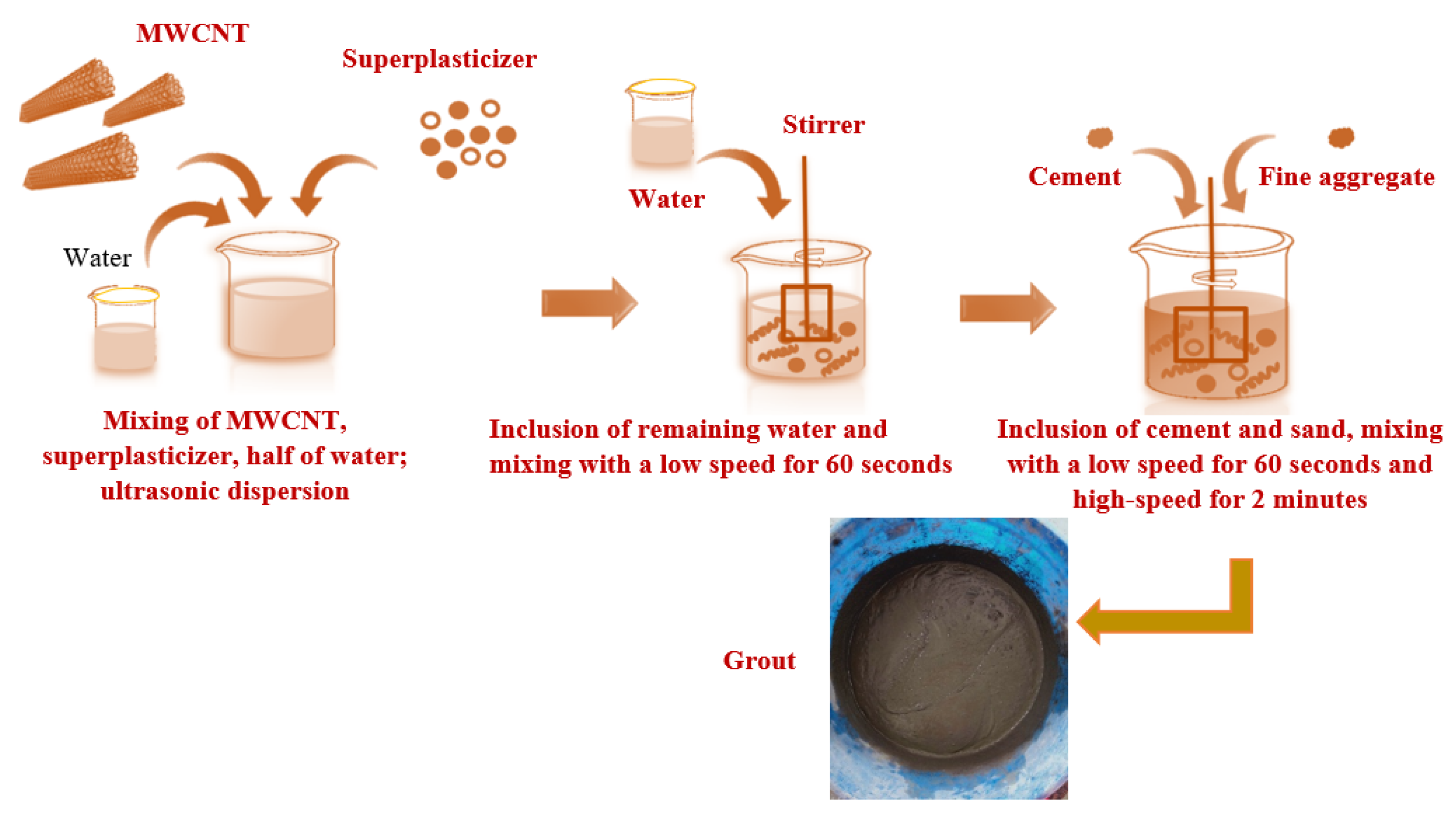
  • Water-reducing admixture named Tec Mix 640 was used as a superplasticiser (SP) to enhance the grout flowability. The used SP had a pH value ranging from 7 to 9 and a relative density of 1.08 at 25 °C. The selection of SP dosage was based on the trial-and-error method by conducting more cone tests that met the efflux time. The SP dosage used was 0.3% for non-fibrous specimens and 0.5% for fibrous specimens.

2.2. Mixing Combination and Insertion of GFM

In total, eight mixtures were produced and addressed separately into two series. Specimens from both series were prepared with a water/binder ratio of 1.0 and binder/sand ratio of 0.45, and these optimised ratios were selected based on a series of cone tests which met the efflux time of (35–40 ± 2 s) according to ASTM C939 [20]. First-series mixtures were prepared with 0.1% of MWCNT and 2.5% of SF together with one, two and three layers of GFM insertion in between the two layers. The mixing combination for the second series was the same as the first series, whereas the dosage of MWCNT was taken as 0.2% (Table 1). The GFM was placed at the middle of the specimen thickness after completion of the first layer of TECAFC, followed by the completion of the second and third layer. The location of the GFM placed in TECAFC is shown in Figure 2.

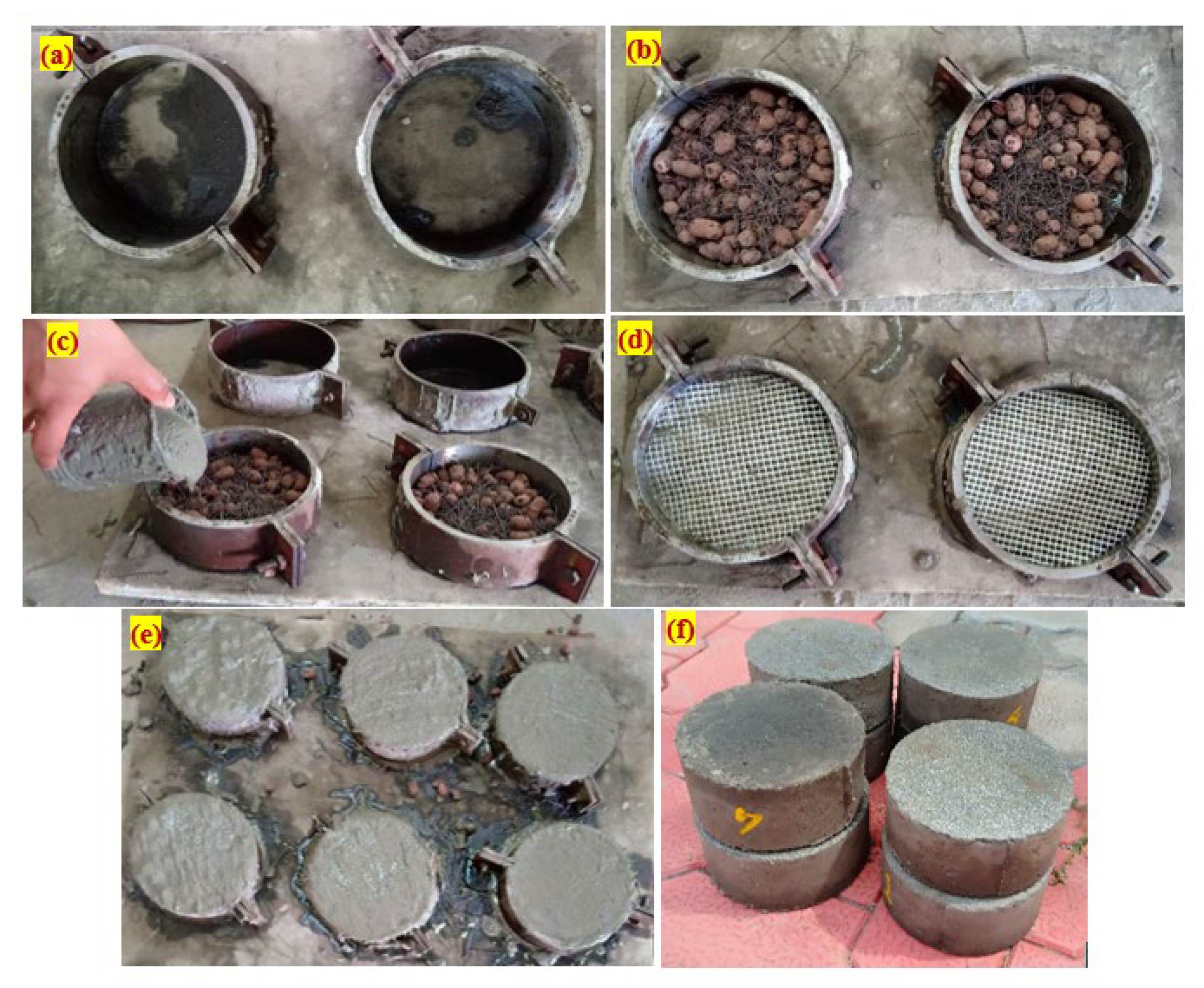
2.3. Specimen Preparation
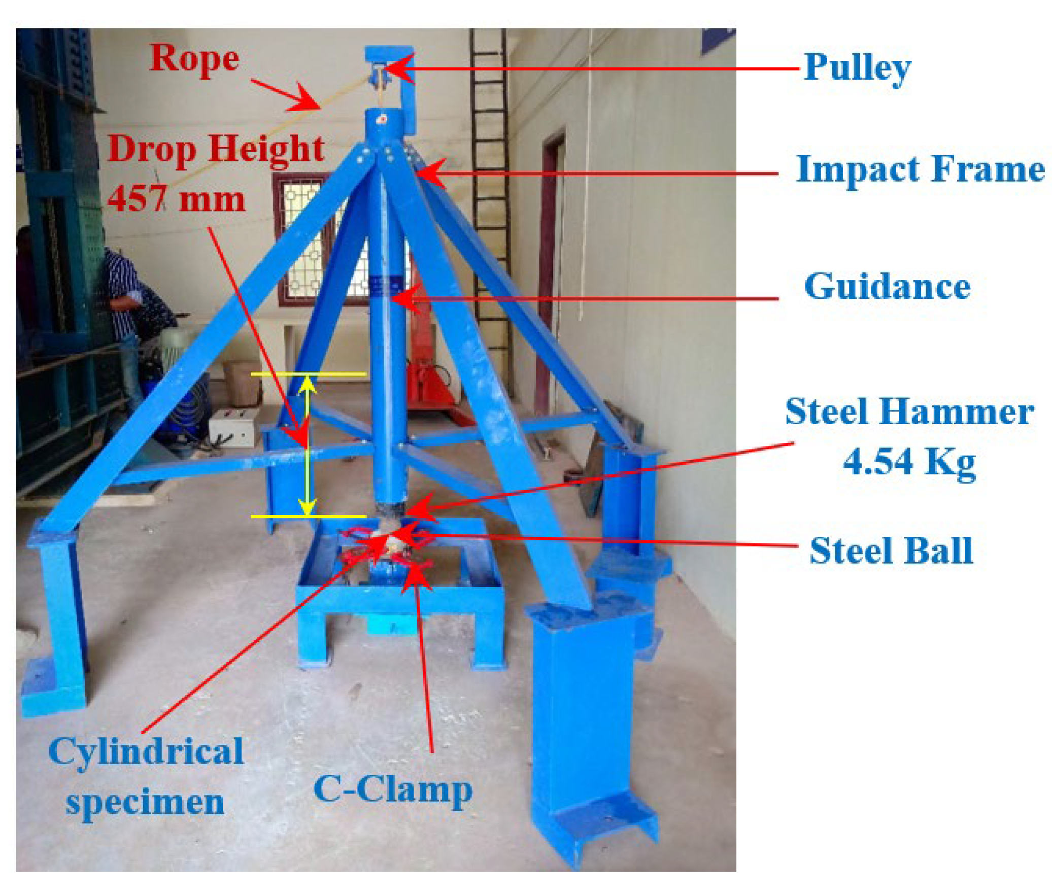
The 152 mm diameter and 64 mm height cylindrical specimens were produced to assess the resistance of TECAFC against impact loading. TECAFC method of casting has two main stages: first, ECA and fibres are mixed before filling into the empty cylindrical mould and then filling mixed ECA and fibres to develop a natural skeleton. Second, the grout comprising cement, sand and MWCNT is poured slowly on the developed skeleton, leading to the filling of voids between the skeletons. The complete sequence of preparing the specimens using the concept of TSC is illustrated in Figure 3. The mixing process of MWCNT involves the stages as follows: first, the MWCNT of the required quantity was mixed with half of the water containing superplasticiser and allowed to stir for 30 min using the mechanical stirrer. Next, the remaining water was added and the process of mixing was prolonged for the next 60 s with a low speed to achieve a dispersed MWCNT. Lastly, the dispersed MWCNT solution was added to a binder and fine aggregate, then the process of mixing was continued for 60 s with a low speed and 120 s with a high speed to achieve a flowable grout. The complete dispersion process of MWCNT is illustrated in Figure 4. In the concept of TSC, a standard and low compaction were applied after finishing the first and second layers to avoid honeycombing and ensuring the grout filling the voids. An insertion of GFM was executed after finishing the first layer, followed by completing the second layer. Upon completing the casting, specimens were allowed to cure at room temperature for 24 h and then the demoulding process was initiated. All specimens were taken out from the mould without any damages and underwent immersion curing for 28 days before testing.

2.4. Testing Setup

ACI Committee 544 [21] falling weight impact was conducted to assess the resistance of TECAFC specimens against impact. It is essential to highlight that the test procedure is very simple and easy to perform, where measurements of time history, vibration and deformations are not required. It is only required to record the numbers of impacts that cause the first surface crack and failure of the test specimen. Figure 5 illustrates the simple falling-mass impact testing setup used to assess the impact resistance. A 4.54 kg steel hammer was repeatedly released from 457 mm height onto the steel ball placed at the specimen’s top surface. To avoid specimen movement in a lateral direction during loading, a C-clamp and four positioning lugs were used. The cracking impact blows (H1) and failure impact blows (H2) were noted. The cracking occurred at the specimen’s top surface, where the point of impact happens and proliferates in a radial direction and towards the specimen’s bottom. Cracking and failure impact blows of TECAFC specimens were noted through visual monitoring.

2.5. Compressive Strength Test and Scanning Electron Microscopy (SEM)

The compressive strength of a 100 mm cubical specimen was evaluated using a compression testing machine of 300 tonnes in accordance with IS 516 [22]. Three cubical specimens were prepared for each mixture and mean values were used for the discussions. The interaction between the cement matrix and MWCNT and its dispersion were found through the scanning electron microscope.

3. Discussion of Results

3.1. Compressive Strength

The recorded compressive strength of 100% ECA-based concrete comprising 0.1 and 0.2% of MWCNT were 19.26 and 22.45 MPa, respectively. Increasing the percentage of MWCNT from 0.1 to 0.2%, the compressive strength increased by about 16.5%. This phenomenon is due to the filling effect and bridging effects of MWCNT; thereby, voids in the matrix were interlinked and significantly improved C-S-H crystals interlocking [23]. Subsequently, excellent compactness with higher density was reached in the concrete microstructure. The earlier study reported that incorporating high dosages of MWCNT leads to decreased strength due to clustering and poor dispersion [23]. However, the obtained compressive strength of ECA-based concrete was deficient due to the lower crushing strength and density of ECA. In common, the bulk density of natural coarse aggregate used in the concrete is 1610 kg/m3, whereas this value is only 300 kg/m3 for ECA [24]. It is worth noting that the ECA is the most vulnerable material in this type of concrete, which plays an essential role in determining compressive strength.
Although the ECA-based concrete exhibited inferior compressive strength, the addition of SF imparted a positive contribution towards increasing strength. For example, with the addition of a 2.5% dosage of SF in ECA-based concrete comprising 0.1 and 0.2% MWCNT, the compressive strength recorded 28.65 and 33.46 MPa, respectively. Compared with non-fibrous specimens comprising 0.1% of MWCNT, the compressive strength of fibrous specimen (2.5% SF + 0.1% MWCNT) was increased by 48.75%. Likewise, the compressive strength of the fibrous specimen (2.5% SF + 0.2% MWCNT) was increased by 49.04%, compared to non-fibrous specimens comprising 0.2% of MWCNT. This phenomenon is due to the presence of fibre in concrete which distributes uniformly, restricting the macro crack formation, alleviating the concentration of stress. Consequently, changing the direction of cracks due to fibre-bridging action leads to delays in crack growth and failure [25,26]. In general, the percentage of SF in conventional fibrous concrete is restricted to 2% due to fibre balling, which creates poor fibre distribution and more internal flaws, leading to reduced compressing strength [27,28]. However, this kind of problem was eradicated in TECAFC since ECA and fibres were premixed and filled into the empty mould before grout injection [29,30]. The percentage of fibre TSC can be used up to 6% to achieve an imperative increase in compressive strength [31,32]. Furthermore, the SF has the potential to bridge cracks at a macroscopic level and higher energy is needed for fibre debonding and pull out, leading to delays in failure and exhibiting superior strength under compression [33,34].

3.2. Impact Strength

Introducing a concrete composite material with high impact resistance is the main goal of numerous research works during the last decades, which was arisen due to the high repair costs of deteriorated concrete members under accidental or repeated impact loads. On the other hand, lightweight structures are in great need in the modern construction industry due to their structural benefits. One of the increasingly used lightweight aggregate types is the ECA, which adversely influence the mechanical properties of the concrete mixture. To introduce concrete mixtures that possess the lightweight structural benefits and overcome the material strength degrading deficiency of ECA, the TECAFC mixtures were introduced with ECA and a multi-scale matrix reinforcement system, which incorporates SF, GFM and MWCNT. To evaluate the overall impact performance of the introduced mixtures and the individual effect of each of the three elements of the reinforcement system, the impact results are discussed in these sections in terms of cracking (H1) and failure (H2) impact numbers in addition to the impact-ductility index (IDI).

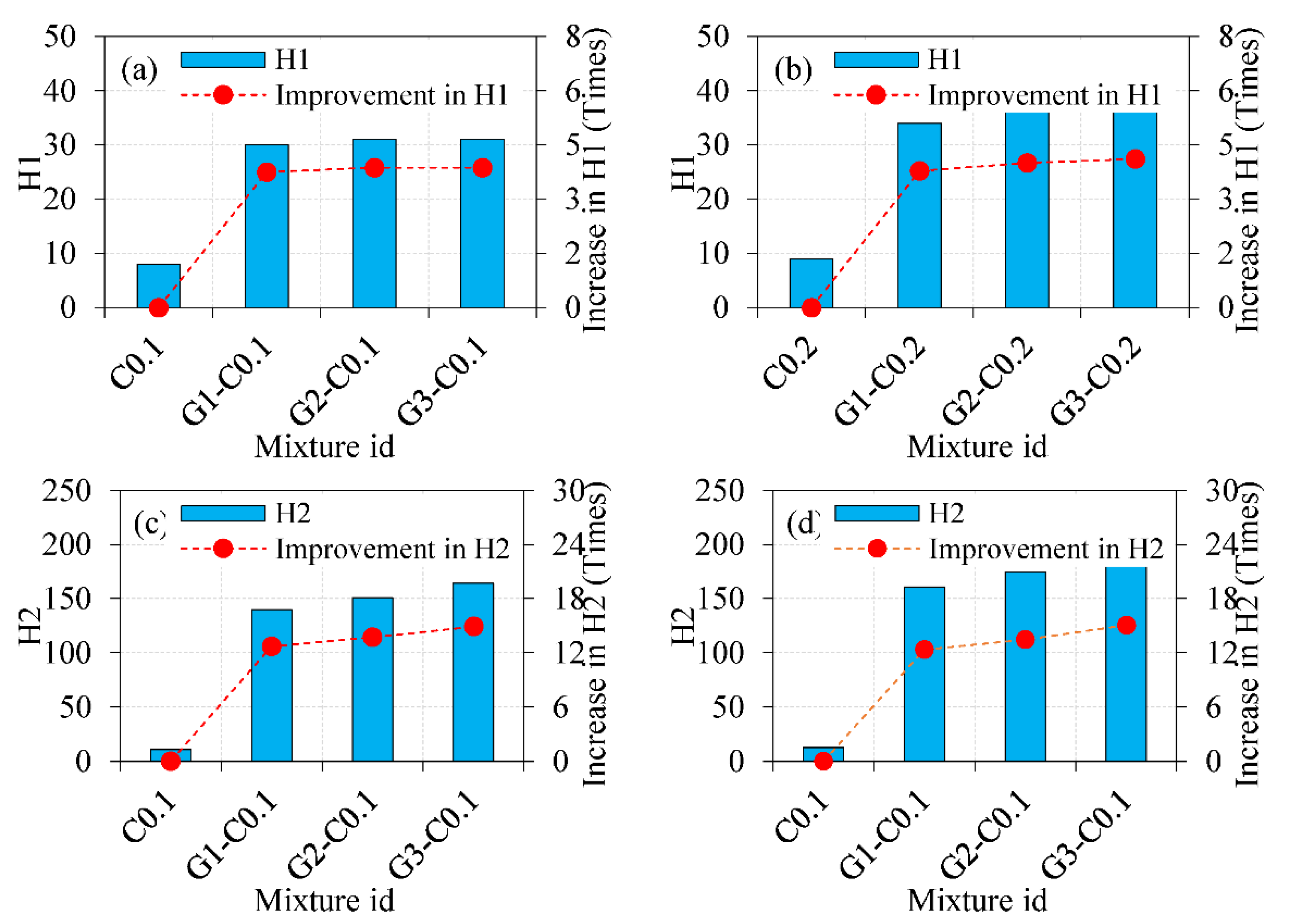
3.2.1. Cracking and Failure Impact Number

Figure 6 shows the initial cracking (H1) and failure (H2) impact numbers of the eight mixtures. Figure 6a,b shows explicitly that the TECAFC mixtures exhibited much higher cracking impact numbers compared to the reference mixtures. For the first group of mixtures with 0.1% MWCNT, the recorded H1 values ranged between 30 and 31 for the fibrous specimens (G1-C0.1, G2-C0.1 and G3-C0.1), while H1 was only eight for the reference mixture of this group (C0.1), which includes the same content of MWCNT but without SF or GFM. This means that a total percentage gain in the cracking impact resistance of 275 to 288% was retained when SF and GFM were used in this group, as illustrated in Figure 6a. Similarly, the cracking impact resistance of the second group (0.2% MWCNT) increased significantly due to the incorporation of SF and GFM, where the percentage increase of G1-C0.2, G2-C0.2 and G3-C0.2 over C0.2 was in the range of 278–311%, as shown in Figure 6b. The increase in the initial cracking resistance is due to the reinforcement activity of steel fibres inside the matrix layers and that of the GFM between the two layers. Due to the repeated impacts on the centre of the test specimen’s top surface, initial surface distortion appears before the first surface crack becomes visible. The surface distortion is accompanied by internal micro-cracking under the concentrated stresses of the repeated impacts. The presence of steel fibres helps controlling crack widening by bridging activity, which alleviates the crack propagation. Consequently, more impacts are required to connect these cracks and develop a visible surface crack. On the other hand, the GFM barricades between the two layers of the TECAFC specimen helps slow down the internal cracks’ connection across this border, which further improves the impact resistance and increases the retained impact numbers [14,28]. Figure 6c shows that the failure impact number H2 increased dramatically from only 11 for the reference specimen C0.1 to 140, 151 and 164 for the fibrous specimens G1-C0.1, G2-C0.1 and G3-C0.1, respectively. Similarly, H2 of the second group jumped from 13 for the reference specimen C0.2 to 161, 175 and 196 for the specimens G1-C0.2, G2-C0.2 and G3-C0.2, respectively, as shown in Figure 6d. This means that a percentage improvement in H2 in the range of 1173–1391% occurred in the first group of specimens (0.1% MWCNT) due to the use of SF and GFM, while the corresponding percentage improvement of the second group (0.2% MWCNT) ranged between 1138 and 1408%.
It is obvious that a very high improvement in impact resistance was gained at the failure stage than that gained at the first cracking stage. In general, the percentage improvement in H2 was more than three times that in H1 for all fibrous mixtures of both groups. This behaviour can be attributed to the bridging action of the steel fibres, where this activity becomes more effective as the tensile stresses along the previously formed micro-cracks increased. Once the first surface crack becomes visible, each additional impact concentrates the tensile stresses along the cracks, trying to make them wider and longer. Depending on their high tensile strength and adequate bond with the matrix, the steel fibres carry most of these stresses across the cracks by bridging activity, which relieves the concentration of stresses on the matrix in this zone and delays the crack widening and propagation [35,36,37]. Due to the high SF content, much higher impact numbers could be absorbed owing to this phenomena after cracking till failure than before cracking.
To evaluate the effect of MWCNT on the impact performance of the tested mixtures, comparisons were made between the specimens of the second group of mixtures (0.2% MWCNT) and their corresponding mixtures of the first group (0.1% MWCNT). The percentage increase in the cracking impact resistance due to increasing the MWCNT content from 0.1 to 0.2% was within a limited range of 12.5–19.4% for all numbers of GFMs. The maximum enhancement in H1 was gained in the G3 specimens, where H1 increased from 31 to 37 as the MWCNT content increased from 0.1 and 0.2%. Similarly, the improvement in the post-cracking impact resistance due to the MWCNT was not high. The percentage enhancement in H2 due to increasing the MWCNT content from 0.1 to 0.2% was almost equivalent to that of H1, where this enhancement was in the range of 15.0–19.5%. Two reasons can explain this limited affectivity. The first is the size range of reinforcement activity of the MWCNTs, where this nanomaterial works as internal cracking reinforcement of the mortar with a maximum crack size of 1 µm [38]. Hence, this reinforcement activity is limited within the early micro-cracks formation period, which occurs at a low number of impacts, as shown in Figure 6. The second reason is that a good dispersion of the MWCNTs in the mortar matrix was not assured, which would affect their distribution and hence their crack bridging activity. This conclusion is discussed in more detail in the SEM analysis section.
The sole effect of using intermediate GFM layers in between the top and bottom layers of the cylindrical specimens are discussed by comparing H1 and H2 records of the specimens incorporating two and three layers with their corresponding specimens with only one layer of GFM. It was concluded in previous research [13,14,28] that using intermediate GFM crack barriers between the material layers led to better crack-arresting performance and increased the absorbed impact energy both before and after crack formation. The findings of this research agree with this conclusion, yet this comparison explores the influence of increasing the number of GFM layers from one to two and three. H1 of the first group was increased by only 3.3% as the number of GFM was increased from one to two and three, while this increment was raised to 5.9 and 8.8% for two and three GFM, respectively, for the second group of mixtures (0.2% MWCNT). Hence, the percentage increase in H1 was in general less than 9% for all cases as three layers of GFM were used instead of the single layer. Similarly, the highest percentage increase in H2 for both groups was 8.7 for two layers of GFM and 21.7 for three layers of GFM.
To evaluate the contribution of each of the three reinforcing materials (SF, GFM and MWCNT), the total improvement in H1 and H2 due to their combined effect (compared with reference specimens C0.1 and C0.2), which is shown in Figure 6, is compared with above-discussed sole effects of GFM and MWCNT. However, this comparison is only to estimate the sole contribution of SF and not to calculate its accurate percentage contribution. Considering the maximum improvement percentages gained by GFM (8.8%) and MWCNT (19.4%), the sole contribution of SF on the enhancement of H1 would not be less than 274%. Similarly, considering the 21.7% and 19.5% maximum improvements in H2 due to GFM and MWCNT, respectively, the improvement in H2 due to the bridging activity of SF can be estimated between 1197 and 1366%. This means that the enhancement in impact resistance of the fibrous mixtures is majorly due to incorporating steel fibres, with a percentage share of not less than 90% of the total percentage impact improvement. The use of steel fibres is widely proven to dramatically improve the fracture behaviour and impact resistance of concrete mixtures [25,39]. The smaller contribution of MWCNT was discussed in the previous paragraphs, while the limited contribution of GFM compared the total improvement in H1 and H2 can be attributed to: first, their localised function as only an intermediate barrier between the two layers, and second, to their lower strength compared to steel fibres. However, considering the fixed content of SF in all fibrous mixtures, it is obvious that increasing the number of GFM layers and the content of MWCNT led to higher retained H1 and H2 values.

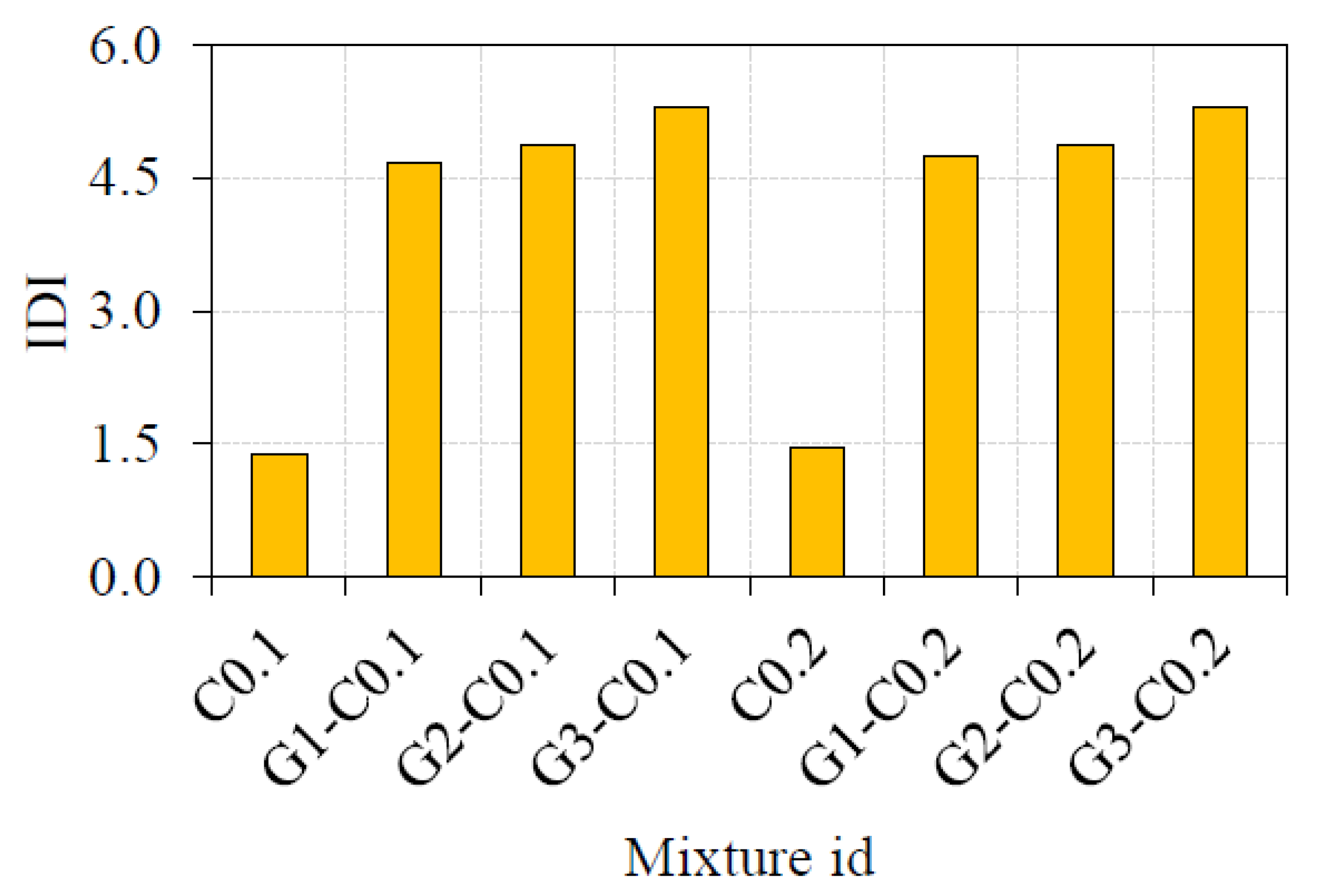
3.2.2. Impact Ductility Index

Ductility is usually used to describe the ability of flexural members to withstand plastic deformation before failure, where ductility index is simply measured as the ratio of ultimate deflection to yield deflection [40]. Therefore, this definition can be utilised for the repeated impact test to show the impact capacity after cracking and till failure. Hence, to describe the impact ductility of a concrete mixture using this test, the impact ductility index can be defined as the ratio of H2 to H1 [14,35]. This definition was utilised to show another side of the material reinforcement effect on the impact response of fibrous mixtures and to distinguish the tested mixtures in terms of ductility.
As shown in Figure 7, the IDI of fibrous mixtures was way higher than for reference specimens. The ductility index of G1-C0.1, G2-C0.1 and G3-C0.1 mixtures was approximately 240, 254 and 285% higher than that of C0.1. Similarly, the IDI values of G1-C0.2, G2-C0.2 and G3-C-0.2 specimens were approximately 228, 237 and 267% higher than that of C0.2. This means that a total percentage improvement in ductility of more than 220% was attained due to the incorporation of the SF and GFM reinforcement materials, which approved the ability of the introduced material reinforcement system to hinder the response from a brittle to a much more ductile one. The stress-absorption capacity of SF across the cracks was the major factor that helped to absorb higher impact loads after crack formation and to postpone failure to several times impacts compared to the reference specimens, which increased the ductility index outstandingly. Both GFM and MWCNT contributed to this enhancement but with much smaller shares than that of SF. Compared to the specimens with one layer of GFM (G1-C0.1 and G1-C0.2), IDI for the specimens with two and three layers increased by 2.7 to 4.4% and 11.9 to 13.4%, respectively. Similarly, compared with their corresponding specimens with 0.1% MWCNT, the IDI of the specimens with 0.2% MWCNT was 15–19.5% higher. This comparison confirms that both GFM and MWCNT have a positive influence on the impact response of the introduced mixtures, but the effect of SF was way higher.

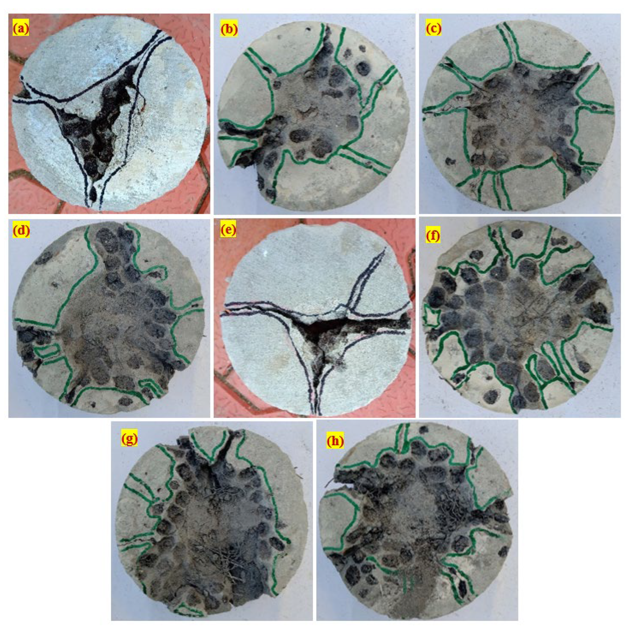
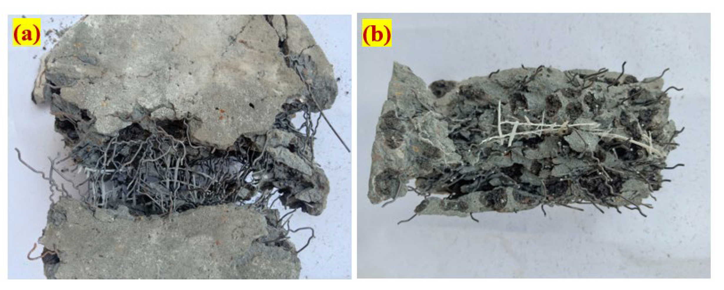
3.2.3. Failure Mode of TECAFC

The failure mode of all tested specimens is shown in Figure 8. All fibrous specimens (comprising SF) showed excellent impact resistance compared to non-fibrous specimens. A sudden failure was observed in non-fibrous specimens after the initial cracking, implying brittle failure mode, as evidenced in Figure 8a,e. In specimens, upon reaching the initial cracking, cracks proliferated in a radial direction and the specimen bottom leading to specimen breaks into two/three pieces. The failure of this type for the non-fibrous cylindrical specimens was anticipated and in good agreement with the earlier studies [41,42]. The reason for this failure mode is the inexistence of bridging action and the brittle nature of concrete [43,44]. The presence of MWCNT in concrete cannot overcome this brittle behaviour.
On the contrary, the impact energy of fibrous specimens improved dramatically by adding a 2.5% dosage of SF, leading to exhibiting a ductile failure. Due to the presence of SF, a more significant number of impacts was observed by SF, leading to the formation of a crater under the steel ball in the critical zone [45]. The damage level of the crater is increased, accompanied by the formation of multiple surface cracks in the radial direction under the repeated impact, evidenced in Figure 8b–d,f–h. The width of these cracks was broadened with increasing impacts, proliferated to the outer perimeter and the bottom surface of the specimen. The fibre in concrete was uninterruptedly bridging the two sides of the cracks, leading to an alleviated bonding between the matrix and fibre, which caused the fibre to pull out, as shown in Figure 9a [46,47]. Figure 9b shows the failure plane of the specimen under impact loading. It is clear from the figure that the fibre was pulled from the cement matrix and the GFM was torn during the crack proliferation. However, providing three layers of GFM resulted in holding the crack proliferation to some extent, delaying failure, and the GFM was torn when it was unable to withstand the impact load. The contribution of SF is more effective in changing the failure mode than the GFM and MWCNT. Figure 9b shows that the trans-granular failure occurred in ECA-based concrete by breaking the ECA due to its low crushing strength, while this failure was intergranular in the case of natural aggregate concrete.

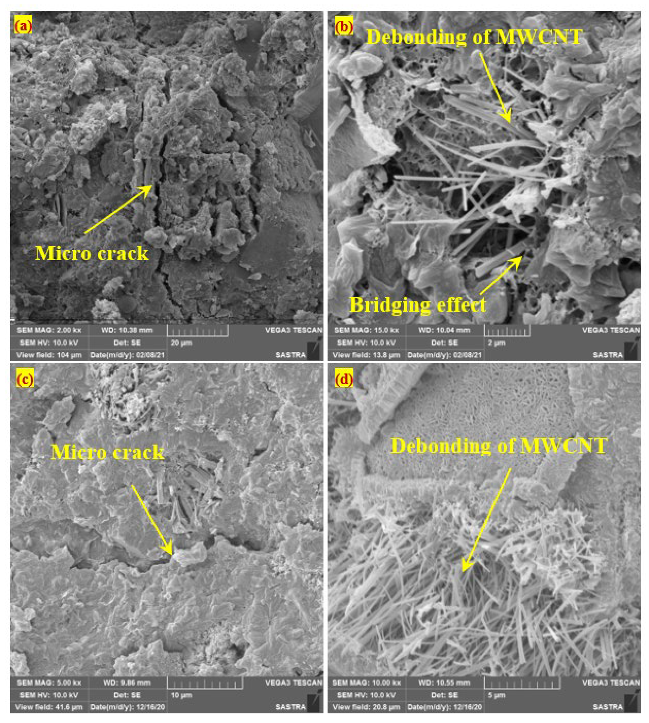
3.2.4. Scanning Electron Microscope

Sample collection for the SEM was taken from the failure plane of the specimens tested under compression. The interaction and dispersion quality of MWCNT with cement matrix was assessed through SEM analysis. Figure 10 shows that the MWCNT were dispersed efficiently with the matrix at 0.1 and 0.2% contents of MWCNT. For all tested specimens comprising MWCNT, an acceptable dispersion quality was achieved in many regions without significant clustering, as shown in Figure 10. In fact, a 0.1% dosage of MWCNT was dispersed regularly between the cracks in some regions that act as reinforcement (Figure 10a). However, a densely packed MWCNT was also visible (Figure 10b), while it was not present in other areas. The excellent reinforcement solution with excellent dispersion quality within the cement matrix failed to reach as anticipated. Nevertheless, the micro-cracks bridging MWCNT was noted in several regions, mainly in specimens with 0.2% MWCNT, as shown in Figure 10c,d. The addition of MWCNT leads to improved hydration products and adhesion between the fibres, resulting in an enhanced mortar’s mechanical strength. Strong-enough interaction between MWCNT and the cement matrix allowed MWCNT in the cracking region to be stretched and potentially acts as nano- to micro-reinforcement. Generally, the width of cracks up to 1 µm can be bridged very effectively by the MWCNT (Figure 10a,c) [38]. Two modes of failure were noticed in the microscopic scale leading to wider micro-cracks, namely, MWCNT fracture and MWCNT debonding or pull-out (Figure 10b,d) [48]. However, the mechanical stirring process of MWCNT dispersion is a good and effective technique for the dosage of MWCNT (0.1 and 0.2%). This phenomenon ensures the potentiality of MWCNT and interaction with superplasticiser physically and chemically that allows the best possible use of MWCNT.

4. Conclusions

In this paper, the combined effect of 100% ECA, GFM of a 150-diameter insertion (three layers), 2.5% of SF, 0.1 and 0.2% of MWCNT on concrete were examined against impact loading. SEM analysis was also conducted to study the interaction between the cement matrix and MWCNT. Based on the detailed investigation, the following specific conclusions can be derived.
  • The compressive strength of concrete comprising 100% ECA and 0.2% MWCNT was increased by 16.5% compared to the reference concrete comprising 0.1% MWCNT + 100% ECA. This improvement resulted from the bridging effects of MWCNT, leading to the voids in the matrix being interlinked and improved C-S-H crystals interlocking. On the other side, the compressive strength of fibrous specimen (2.5% SF + 0.1% MWCNT) was increased by 48.75% compared with non-fibrous specimens (0.1% MWCNT). Compared to the specimen (0.2% MWCNT), the strength increased further by 49.04% when 2.5% SF and 0.2% MWCNT were incorporated. This improvement is due to the presence of SF, which can bridge the macro cracks and delay the failure. The contribution of SF is more significant in improving compressive strength than the MWCNT.
  • The triple multi-scale reinforcement composed of SF, GFM and MWCNT enhanced the impact resistance of the adopted mixtures significantly. The incorporation of SF and GFM in the fibrous mixtures improved the cracking impact resistance (H1) by 275–311% compared to reference specimens incorporating the same MWCNT contents. Similarly, the failure impact number (H2) was increased by more than 1100% compared to the reference specimens. Comparing the obtained impact records of the eight mixtures, it can be said that at least 90% of the total impact resistance improvement is attributed to the bridging activity of steel fibres, while the contributions of GFM and MWCNT were way smaller than that of steel fibres.
  • The incorporation of SF and GF mesh has a dramatic influence on the behaviour of test specimens under impact loads, where this behaviour was shifted from a brittle to a much more ductile one with a way higher ductility index. The ductility index (IDI) of the fibrous specimens of both groups (0.1 and 0.2% of MWCNT) increased by 228–285% compared to the reference specimens with the same contents of MWCNT. The crack width and length-arresting capacity of steel fibres was the major effective factor that helped to withstand higher post-cracking impact loads, which outstandingly increased the ductility index, while as for the impact number records, the GFM and MWCNT contributed the ductility improvement, but with much smaller shares compared to that of SF.
  • Two different failure modes were recorded: brittle and ductile. All non-fibrous displayed a sudden failure after the initial cracking, which exhibiting the failure brittle in nature. On the other side, all fibrous specimens experienced multiple cracks in radial directions, leading to the failure in a ductile manner. The MWCNT has not changed the failure mode from brittle to ductile, while SF did.
  • The mechanical strength of the cement matrix was improved by incorporating MWCNT, which can improve hydration products and adhesion between the fibres. Strong-enough interaction between MWCNT and the cement matrix allowed MWCNT in the cracking region to be stretched and potentially act as micro-reinforcement.

Author Contributions

Conceptualisation, G.M. and S.R.A.; methodology, G.M.; software, G.M.; validation, G.M.; formal analysis, G.M.; investigation, G.M.; resources, G.M.; data curation, G.M.; writing—original draft preparation, G.M., S.R.A. and M.A.; writing—review and editing, G.M., N.V. and R.F.; visualisation, G.M.; supervision, G.M.; project administration, G.M.; funding acquisition, N.V., M.K. and R.F. All authors have read and agreed to the published version of the manuscript.

Funding

The research is partially funded by the Ministry of Science and Higher Education of the Russian Federation as part of the World-class Research Center program: Advanced Digital Technologies (contract No. 075-15-2020-934 dated 17 November 2020).

Institutional Review Board Statement

Not applicable.

Informed Consent Statement

Not applicable.

Data Availability Statement

Data can be shared upon direct request.

Acknowledgments

The author acknowledge the support from the School of Civil Engineering, SASTRA Deemed University and the Ramco Cement chair professor for the financial support provided to develop the impact-testing device.

Conflicts of Interest

The authors declare no conflict of interest.

References

  1. Alexander, M.G.; Arliguie, G.; Ballivy, G.; Bentur, A.; Marchand, J. Engineering and Transport Properties of the Interfacial Transition Zone in Cementitious Composites; RILEM Publications: Paris, France, 1999. [Google Scholar]
  2. Alaa, M.R. Lightweight expanded clay aggregate as a building material—An Overview. Constr. Build. Mater. 2018, 170, 757–775. [Google Scholar]
  3. Ozguven, A.; Gunduz, L. Examination of effective parameters for the production of expanded clay aggregate. Cem. Concr. Compos. 2012, 34, 781–787. [Google Scholar] [CrossRef]
  4. Priyanga, R.; Rajeshwari, L.B.; Baskar, S. Experimental investigation on mechanical properties of lightweight concrete using LECA and steel scraps. SSRG Int. J. Civ. Eng. 2017, 594–598. [Google Scholar]
  5. Scotta, R.; Giorgi, P. Comparative cyclic tests of exterior flat slab column connections in normal concrete and fiber-reinforced lightweight aggregate concrete. Mater. Struct. 2016, 49, 4049–4067. [Google Scholar] [CrossRef]
  6. Bocca, P.; Rossetti, U. Investigation on the cracking behavior of lightweight concrete. Matér. Construct. 1978, 11, 261–268. [Google Scholar] [CrossRef]
  7. Khafaga, M.A. Shear behavior of reduced-weight reinforced concrete beams. J. Eng. Sci. Assiut Uni. 2012, 40, 121–146. [Google Scholar] [CrossRef]
  8. Najjar, M.F.; Soliman, A.M.; Nehdi, M.L. Critical overview of two-stage concrete: Properties and applications. Constr. Build. Mater. 2014, 62, 47–58. [Google Scholar] [CrossRef]
  9. Nehdi, M.L.; Najjar, M.F.; Soliman, A.M.; Azabi, T.M. Novel steel fiber-reinforced preplaced aggregate concrete with superior mechanical performance. Cem. Concr. Compos. 2017, 82, 242–251. [Google Scholar] [CrossRef]
  10. Murali, G.; Ramprasad, K. A feasibility of enhancing the impact strength of novel layered two stage fibrous concrete slabs. Eng. Struct. 2018, 175, 41–49. [Google Scholar] [CrossRef]
  11. Abirami, T.; Loganaganandan, M.; Murali, G.; Roman, F.; Vickhram Sreekrishna, R.; Vignesh, T.; Januppriya, G.; Karthikeyan, K. Experimental research on impact response of novel steel fibrous concretes under falling mass impact. Constr. Build. Mater. 2019, 222, 447–457. [Google Scholar] [CrossRef]
  12. Abirami, T.; Murali, G.; Saravana Raja Mohan, K.; Salaimanimagudam, M.P.; Nagaveni, P.; Bhargavi, P. Multi-layered two stage fibrous composites against low-velocity falling mass and projectile impact. Constr. Build. Mater. 2020, 248, 118631. [Google Scholar] [CrossRef]
  13. Haridharan, M.K.; Matheswaran, S.; Murali, G.; Abid, S.R.; Roman, F.; Mugahed, A.; Hakim, S.A. Impact response of two-layered grouted aggregate fibrous concrete composite under falling mass impact. Constr. Build. Mater. 2020, 263, 120628. [Google Scholar] [CrossRef]
  14. Murali, G.; Abid, S.R.; Mugahed Amran, Y.H.; Abdelgader, H.S.; Roman, F.; Arikatla, S.; Poonguzhali, K. Impact performance of novel multi-layered prepacked aggregate fibrous composites under compression and bending. Structures 2020, 28, 1502–1515. [Google Scholar] [CrossRef]
  15. Li, G.Y.; Wang, P.M.; Zhao, X.H. Mechanical behavior and microstructure of cement composites incorporating surface-treated multi-walled carbon nanotubes. Carbon 2005, 43, 1239–1245. [Google Scholar] [CrossRef]
  16. Al-Rub, R.K.A.; Ashour, A.I.; Tyson, B.M. On the aspect ratio effect of multiwalled carbon nanotube reinforcements on the mechanical properties of cementitious nanocomposite. Constr. Build. Mater. 2012, 35, 647–655. [Google Scholar] [CrossRef]
  17. Murali, G.; Sallal, R.A.; Karthikeyan, K.; Haridharan, M.K.; Mugahed, A.; Siva, A. Low-Velocity impact response of novel prepacked expanded clay aggregate fibrous concrete produced with carbon nano tube, glass fiber mesh and steel fiber. Constr. Build. Mater. 2021, 284, 122749. [Google Scholar] [CrossRef]
  18. Bureau of Indian Standards (BIS). Code of Practice for 53 Grade Ordinary Portland Cement; Standard No. IS-12269: 2008; BIS: New Delhi, India, 1987. [Google Scholar]
  19. Bureau of Indian Standards (BIS). Code of Practice—Specification for Coarse and Fine Aggregate from Natural Sources for Concrete; Standard No. IS-383: 2002; BIS: New Delhi, India, 1970. [Google Scholar]
  20. ASTM C939/C939M-16a. Standard Test Method for Flow of Grout for Preplaced-Aggregate Concrete (Flow Cone Method); ASTM C939/C939M-16a; ASTM International: West Conshohocken, PA, USA, 2016. [Google Scholar]
  21. ACI 544-2R. Measurement of Properties of Fiber Reinforced Concrete; American Concrete Institute: Farmington Hills, MI, USA, 1999. [Google Scholar]
  22. IS: 516-1959. In Indian Standard Method of Tests for Strength of Concrete; Reaffirmed, Bureau of Indian Standard: New Delhi, India, 2004.
  23. Mohammad, R.I.; Ammar, A.-S. Using textile reinforced mortar modified with carbon nano tubes to improve flexural performance of RC beams. Compos. Struct. 2018, 200, 127–134. [Google Scholar]
  24. Ali, H.N.; Ali, K.K. Influence of content and maximum size of light expanded clay aggregate on the fresh, strength, and durability properties of self-compacting light-weight concrete reinforced with micro steel fiber. Constr. Build. Mater. 2020, 233, 117922. [Google Scholar]
  25. Jabir, H.A.; Sallal, R.A.; Gunasekaran, M.; Sajjad, H.A.; Klyuev, S.; Roman, F.; Vatin, N.; Promakhov, V.; Vasilev, Y. Experimental Tests and Reliability Analysis of the Cracking Impact Resistance of UHPFRC. Fibers 2020, 8, 74. [Google Scholar] [CrossRef]
  26. Abid, S.R.; Abdul-Hussein, M.L.; Ayoob, N.S.; Ali, S.H.; Kadhum, A.L. Repeated drop-weight impact tests on self-compacting concrete reinforced with micro-steel fiber. Heliyon 2020, 6, 1–11. [Google Scholar] [CrossRef] [Green Version]
  27. Salaimanimagudam, M.P.; Suribabu, C.R.; Murali, G.; Abid, S.R. Impact response of hammerhead pier fibrous concrete beams designed with topology optimization. Period. Polytech. Civ. Eng. 2020, 64, 1244–1258. [Google Scholar] [CrossRef]
  28. Murali, G.; Sallal, R.A.; Hakim, S.A.; Mugahed Amran, Y.H.; Shekarchi, M.; Wilde, K. Repeated Projectile Impact Tests on Multi-Layered Fibrous Cementitious Composites. Inter. J. Civil. Eng. 2021, 19, 635–651. [Google Scholar] [CrossRef]
  29. Nandhu, P.; Murali, G. Research on flexure and impact performance of functionally-graded two-stage fibrous concrete beams of different sizes. Constr. Build. Mater. 2021, 288, 123138. [Google Scholar]
  30. Meivazhisalai, P.S.; Gunasekaran, M.; Vivek Vardhan, C.M.; Amran, M.; Vatin, N.; Roman, F.; Vasilev, Y. Impact Response of Preplaced Aggregate Fibrous Concrete Hammerhead Pier Beam Designed with Topology Optimization. Crystals 2021, 11, 147. [Google Scholar]
  31. Nandhu, P.; Gunasekaran, M.; Roman, F.; Vatin, N.; Karelina, M. Response of Novel Functionally-Graded Prepacked Aggregate Fibrous Concrete against Low Velocity Repeated Projectile Impacts. Materials 2021, 14, 280. [Google Scholar]
  32. Loganaganandan, M.; Murali, G.; Salaimanimagudam, M.P.; Haridharan, M.K.; Karthikeyan, K. Experimental study on GFRP strips strengthened new two stage concrete slabs under falling mass collisions. KSCE J. Civ. Eng. 2021, 25, 235–244. [Google Scholar] [CrossRef]
  33. Jaishankar, P.; Murali, G.; Salaimanimagudam, M.P.; Amran, Y.H.M.; Fediuk, R.; Karthikeyan, K. Study of topology optimized hammerhead pier beam made with novel preplaced aggregate fibrous concrete. Period. Polytech. Civ. Eng. 2021, 65, 287–298. [Google Scholar] [CrossRef]
  34. Rithanyaa, R.; Murali, G.; Salaimanimagudam, M.P.; Roman, F.; Hakim, S.A.; Siva, A. Impact response of novel layered two stage fibrous composite slabs with different support type. Structures 2021, 29, 1–13. [Google Scholar] [CrossRef]
  35. Sallal, R.A.; Murali, G.; Sajjad, H.A.; Ahmed, L.K.; Thaar, S.A.-G.; Roman, F.; Vatin, N.; Karelina, M. Impact Performance of Steel Fiber-Reinforced Self-Compacting Concrete against Repeated Drop Weight Impact. Crystals 2021, 11, 91. [Google Scholar]
  36. Arnaot, F.H.; Abbass, A.A.; Abualtemen, A.A.; Abid, S.R.; Özakça, M. Residual strength of high strength concentric column-SFRC flat plate exposed to high temperatures. Constr. Build. Mater. 2017, 154, 204–218. [Google Scholar] [CrossRef]
  37. Abbass, A.A.; Abid, S.R.; Özakça, M. Experimental investigation on the effect of steel fibers on the flexural behavior and ductility of high-strength concrete hollow beams. Adv. Civ. Eng. 2019, 2019, 1–13. [Google Scholar] [CrossRef]
  38. Dong, S.; Wang, D.; Ashour, A.; Han, B.; Ou, J. Nickel plated carbon nanotubes reinforcing concrete composites: From nano/micro structures to macro mechanical properties. Compos. Part A. 2021, 141, 106228. [Google Scholar] [CrossRef]
  39. Sallal, R.A.; Munther, L.A.; Sajjad, H.A.; Alaa, F.K. Suggested modified testing techniques to the ACI 544-R repeated drop-weight impact test. Constr. Build. Mater. 2020, 244, 118321. [Google Scholar]
  40. Abbass, A.A.; Abid, S.R.; Arnaot, F.H.; Al-Ameri, R.A.; Özakça, M. Flexural response of hollow high strength concrete beams considering different size reductions. Structures 2019, 23, 69–86. [Google Scholar] [CrossRef]
  41. Murali, G.; Santhi, A.S.; Mohan Ganesh, G. Effect of Crimped and Hooked End Steel Fibres on the Impact Resistance of Concrete. J. Appl. Sci. Eng. 2014, 17, 259–266. [Google Scholar]
  42. Murali, G.; Laxminadh, P.; Parthiban, K.; Haridharan, M.K.; Siva, A. Impact Response of Novel Fibre-Reinforced Grouted Aggregate Rubberized Concrete. Arabian. J. Sci. Eng. 2019, 44, 8451–8463. [Google Scholar]
  43. Murali, G.; Neha, P.A.; Ramkumar, V.R.; Siva, A.; Haridharan, M.K. Impact Resistance and Strength Reliability of Novel Two-Stage Fibre-Reinforced Concrete. Arab. J. Sci. Eng. 2019, 44, 4477–4490. [Google Scholar] [CrossRef]
  44. Neha, P.A.; Murali, G.; Parthiban, K.; Surya, K.; Prakash, A.; Rathika, K.; Chandru, U. A feasibility of enhancing the impact resistance of hybrid fibrous geopolymer composites: Experiments and modelling. Constr. Build. Mater. 2019, 203, 56–68. [Google Scholar]
  45. Murali, G.; Muthulakshmi, T.; Nycilin Karunya, N.; Iswarya, R.; Hannah, J.G.; Karthikeyan, K. Impact Response and Strength Reliability of Green High-Performance Fibre Reinforced Concrete Subjected to Freeze-Thaw Cycles in NaCl Solution. Mater. Sci. Medzg. 2017, 23, 384–388. [Google Scholar]
  46. Sallal, R.A.; Gunasekaran, M.; Amran, M.; Vatin, N.; Roman, F.; Karelina, M. Evaluation of Mode II Fracture Toughness of Hybrid Fibrous Geopolymer Composites. Materials 2021, 14, 349. [Google Scholar]
  47. Murali, G.; Roman, F.A. Taguchi approach for study on impact response of ultra-high-performance polypropylene fibrous cementitious composite. J. Build. Eng. 2020, 30, 101301. [Google Scholar] [CrossRef]
  48. Carriço, A.; Bogas, J.A.; Hawreen, A.; Guedes, M. Durability of multi-walled carbon nanotube reinforced concrete. Constr. Build. Mater. 2018, 164, 121–133. [Google Scholar] [CrossRef]
Figure 1. Materials used in this research: (a) Expanded clay aggregate; (b) Multi-walled carbon nanotube; (c) Steel fibre; (d) Glass fibre mesh of 150 mm diameter.
Crystals 11 00720 g001
Figure 2. Glass fibre mesh insertion location.
Crystals 11 00720 g002
Figure 3. Casting method. (a) Empty cylindrical mould; (b) ECA and fibres are premixed and filled into the empty mould; (c) Grout pouring; (d) GFM insertion after the first layer of concrete; (e) Finished specimens; (f) Appearance of the specimen after demoulding.
Crystals 11 00720 g003
Figure 4. MWCNT mixing method to develop grout.
Crystals 11 00720 g004
Figure 5. Impact-testing setup.
Crystals 11 00720 g005
Figure 6. Initial cracking and failure impact numbers (a) H1 with 0.1% MWCNT, (b) H1 with 0.2% MWCNT, (c) H2 with 0.1% MWCNT, (d) H2 with 0.2% MWCNT.
Crystals 11 00720 g006
Figure 7. Ductility index of composite.
Crystals 11 00720 g007
Figure 8. Failure mode of specimens subjected to impact load (a) C0.1, (b) G1-C0.1, (c) G2-C0.1, (d) G3-C0.1, (e) C0.2, (f) G1-C0.2, (g) G2-C0.2, (h) G3-C0.2.
Crystals 11 00720 g008
Figure 9. Fibre failure. (a) Fibre bridging; (b) Appearance of failure plane.
Crystals 11 00720 g009
Figure 10. SEM images specimens. (a) Micro crack in specimens comprising 0.1% MWCNT; (b) Debonding of specimen comprising 0.1% MWCNT; (c) Micro crack in specimens comprising 0.2% MWCNT; (d) Debonding of specimen comprising 0.2% MWCNT.
Crystals 11 00720 g010
Table 1. Mixing composition of TECAFC.
SeriesMixture Ids/bw/bDiameter of GFM (mm)Layers of GFMMWCNTs (%)Dosage of Fibre (%)SP (%)
1C0.11.00.45000.100.3
G1-C0.11.00.4515010.12.50.5
G2-C0.11.00.4515020.12.50.5
G3-C0.11.00.4515030.12.50.5
2C0.21.00.45000.200.3
G1-C0.21.00.4515010.22.50.5
G2-C0.21.00.4515020.22.50.5
G3-C0.21.00.4515030.22.50.5
Publisher’s Note: MDPI stays neutral with regard to jurisdictional claims in published maps and institutional affiliations.

