
A Review of Two-Dimensional Liquid Crystal Polarization Gratings


1
School of Physical Science and Technology, Ningbo University, No. 818 Fenghua Road, Jiangbei District, Ningbo 315211, China
2
Department of Electrical and Electronic Engineering, Southern University of Science and Technology, No. 1088 Xueyuan Road., Xili, Nanshan District, Shenzhen 518055, China
*
Authors to whom correspondence should be addressed.
Crystals 2021, 11(9), 1015; https://0-doi-org.brum.beds.ac.uk/10.3390/cryst11091015
Submission received: 8 August 2021
/
Revised: 19 August 2021
/
Accepted: 19 August 2021
/
Published: 25 August 2021
(This article belongs to the Special Issue Liquid Crystals in China)
Abstract
:In the past two decades, polarization gratings (PGs) have attracted intensive attention due to the high-efficient diffraction and polarization selectivity properties. On one hand, the one-dimensional (1D) PGs have been investigated widely and adapted to various applications. On the other hand, optical signal manipulation stimulates the development of multibeam optical devices. Therefore, the development of two-dimensional (2D) PGs is in demand. This review summarizes the research progress of 2D PGs. Different designs and fabrication methods are summarized, including assembling two 1D polarization patterns, a 2D holographic lithography by polarization interference and a micro-pixelated electric field stimulated 2D liquid crystal (LC) structure. Both experiments and analyses are included. The design strategy, diffraction property, merits and demerits are discussed and summarized for the different methods.
1. Introduction
Light polarization is a key parameter of light. Various applications, such as biomimetics, imaging system and quantum communication, have been developed rapidly based on this feature [1,2,3,4,5]. Therefore, the efficient control of light polarization is of importance. Besides a traditional polarization beam splitter, recently developed PGs provide great potentiality for highly efficient polarization beam splitting and polarization conversion [6,7]. PGs are usually fabricated based on LC materials to provide tunable anisotropy for light modulation. Different from traditional diffraction gratings using a binary LC structure, the PG requires a fine patterning of LC directors, whose fabrication costs and time requirements are highly based on methods such as micro-rubbing and imprinting [8,9]. In contrast, polarization-sensitive materials provide an effective and convenient way for PG realization [10,11,12,13,14], where photosensitive LC polymers and photoalignment technology have been applied widely for LC PG fabrication [15,16,17].
In the past two decades, 1D circular PGs have been investigated thoroughly. The interference of two orthogonally circularly polarized (CP) beams with equal intensity gives a uniform intensity distribution and a 1D modulated linearly polarized (LP) light field with a periodicity of Λ = λ/2sinθ, where θ is the interference angle between the two beams [18,19]. With the help of birefringent materials such as LCs, the in-plane birefringence varies with the position as n(x) = [sin(πx/Λ), cos(πx/Λ),0]. The diffraction of 1D PG, calculated based on Fourier transform and a Jones matrix, has only the 0th and ±1st orders, with diffraction efficiencies of [17]:
where Γ = 2π∆nd/λ is the phase retardation, λ is the incident light wavelength and S3´ = S3/ S0 is the normalized Stokes parameter. The 0th order keeps the same polarization as the incidence, whereas the ±1st orders are polarization-sensitive and are always orthogonally CP, regardless of the input polarization state. In addition, the diffraction efficiency of the 0th and the 1st orders can be tuned between 0% and 100% by adjusting the phase retardation. At the half-wave condition (∆nd = λ/2), the 1D PG could reach 100% diffraction efficiency on the 1st order, which is much higher than the traditional binary 1D grating.
η0 = cos2(Γ/2),
η±1 = 1/2 (1 ∓ S3´) sin2(Γ/2),
The 1D PG has attracted intensive attention, and various optical devices such as achromatic PGs, beam steering devices, a highly efficient polarizer and distributed feedback lasers have been studied extensively based on it [20,21,22,23,24,25,26,27,28,29]. On the other hand, optical signal manipulation has stimulated the development of multibeam optical devices. Therefore, 2D PGs with high diffraction efficiency and polarization selectivity are in demand. Here, a brief review is given for the 2D polarization diffraction devices. The design strategy, diffraction property, merits and demerits are discussed and summarized for the different methods.
2. 2D PGs by Assembling Two 1D Polarization Patterns
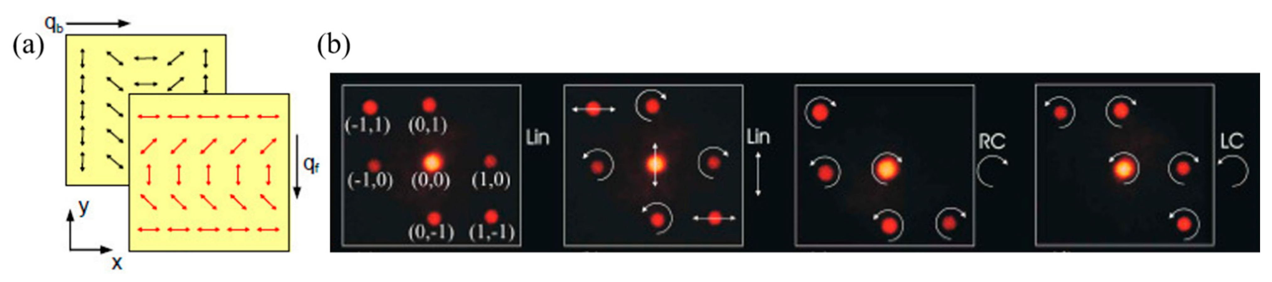
Inspired by 1D PG, Crawford et al. firstly demonstrated a 2D LC PG by cross-assembling two 1D polarization patterns in 2005 [15]. Subsequently, Provenzano et al. fabricated a 2D PG in the same way and investigated the diffraction and polarization properties in detail [30]. In their design, each substrate was individually exposed to the interference patterns of two orthogonally CP beams at the same conditions, and then, the two substrates were cross-assembled into a cell for nematic LC filling. The diffraction gave strong (0, 0), (±1, 0), (0, ±1), (−1, 1) and (1, −1) orders, as shown in Figure 1. However, the diffraction property was found complicated in this case, where both the diffraction efficiency and polarization state could be influence by the cell thickness. Therefore, a detailed investigation was demanded, and several studies contributed to the analysis in the following years [31,32,33,34,35].
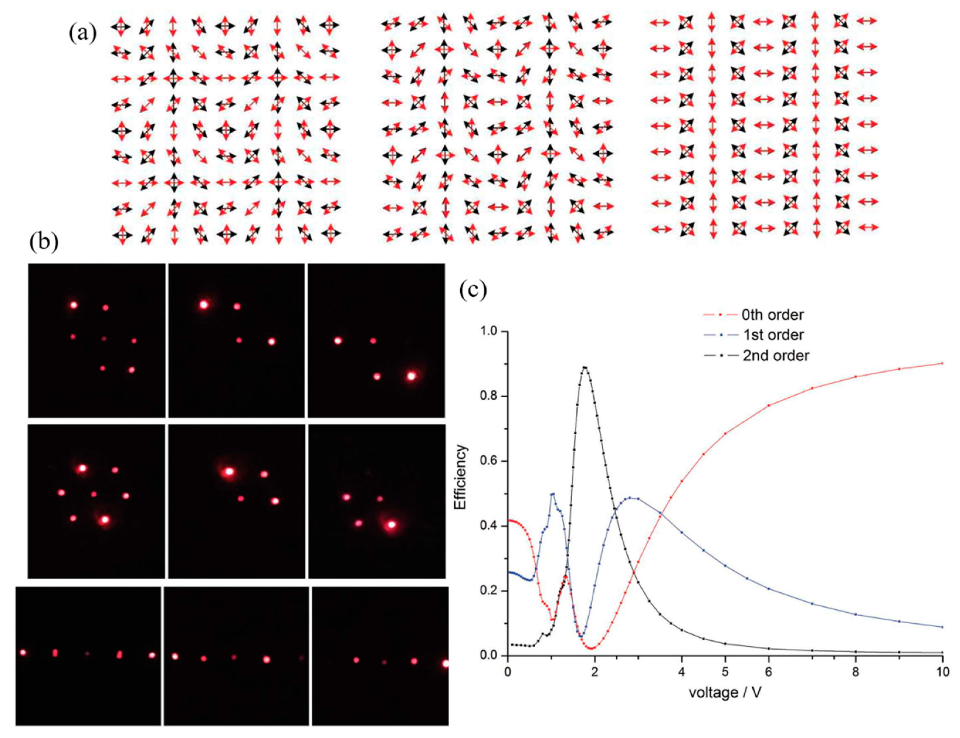
In 2019. Z.-H. Peng et al. fabricated the 2D LC PGs with different crossing angles (π/2, 3π/4 and π, respectively) on the top and bottom substrates (Figure 2a) [31]. The authors applied a simplified model that the LC molecules in the mid-plane aligned vertically to the substrates to avoid a twist deformation. To realize this, a strong surface anchoring strength and enough cell thickness were required in the experiment, and proper external voltage was applied to guarantee vertical director orientation in the bulk. Seven diffraction spots were observed, as shown in Figure 2b, similar to the observation in Figure 1 [30].
In this simplified model, the 2D PG could be considered as a stack of two individual 1D PGs, and the diffraction property could be simply calculated based on Fourier transform and a Jones matrix. The calculations indicate that the diffraction angle of the 2D PG is controlled by both the crossing angle and the grating pitch, while the diffraction efficiency is determined by the phase retardation and the polarization state of the incident beam as follows (modified from Reference [31] to be consistent with Equations (1) and (2):
η(0, 0) = cos⁴(Γ/2),
η(±1, 0) = 1/2 (1 ∓ S3’) sin2(Γ/2) cos2(Γ/2),
η(0, ±1) = 1/2 (1 ∓ S3’) sin2(Γ/2) cos2(Γ/2),
η(±1, ∓1) = 1/2 (1 ± S3’) sin⁴(Γ/2).
Based on the calculations and experiment, the polarization states of the 0th order of (0, 0) and 1st orders of (±1, 0) and (0, ±1) are the same as the 1D PG with modified diffraction efficiency, where the 1st order exhibits CP states with polarization selectivity and the 0th order is the same as the incident beam. On the other hand, the polarization states of (1, −1) and (−1, 1), which are marked as the ±2nd orders in Figure 2c, exhibit a CP state that is conserved with the CP incidence. Since the two stacks operate as two independent 1D PGs, the diffraction on the 2nd order is a result of two 1st-order diffractions of the two stacks in sequence. The CP polarization state reverses twice, giving the same polarization helicity as the incidence on the 2nd order. At the half-wave conditions of each stack, the incident light is mainly diffracted into the 2nd order, occupying up to 90% of the diffraction energy in the experiment, as shown in Figure 2c. It is noted that this analysis is only valid when the LC directors in the mid-plane are oriented vertically in the bulk and no twist deformation exists.
In 2008, A.Y.-G. Fuh et al. studied the 2D LC PG assembled by two crossed 1D polarization patterns without external voltage in a more general way [32]. They simulated the LC orientation and phase modulation by dividing the LC layer into N equal sublayers in an array along the z-axis and calculated based on Jones calculus. The study gave a web of disclination lines at the boundary of the square lattices, as shown in Figure 3a. The diffraction of the 2D PG has the main orders of (0, 0), (±1, 0) and (0, ±1), as shown in Figure 3b. The 0th order retains the polarization of the incident beam, while the (±1, 0) and (0, ±1) orders are elliptically polarized (EP) with the long axis perpendicular to the polarization of the LP incident beam. However, the diffraction efficiency is low in this case due to the existence of the disclination lines (Figure 3c). In 2017, H. Yokoyama et al. observed the same web of disclination lines (Figure 3d) [33]. Their investigation indicates that the disclination lines are generated near the top and bottom substates in perpendicular directions, as shown in Figure 3e, where the lattice points are pinned at the points with parallel alignment on both substrates. The study shows that the square web of disclination lines is metastable, since the straight disclination lines are not in mechanical equilibrium with the unbalanced twist deformation. However, the disclination line tension is found to be large enough to be sustained with substrate shearing when the LC structure has a proper thickness and pattern pitch.
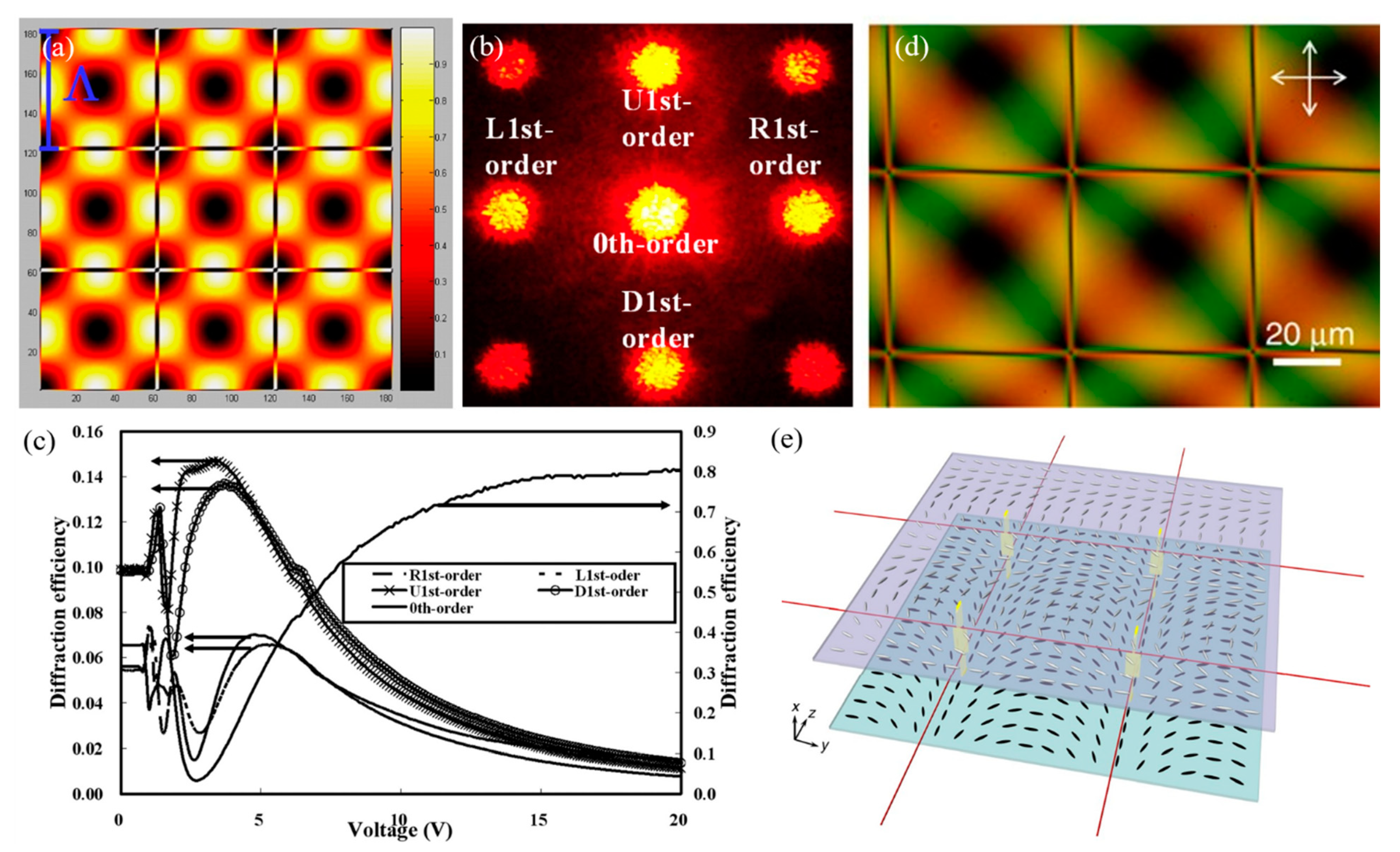
In 2015, I. Nys et al. used finite element simulations and the Q-tensor theory to analyze the complex 3D LC configuration in a cell assembled by two crossed 1D polarization patterns [34]. The result showed that, when the ratio of the grating period Λ over the cell thickness d decreased, a symmetry break took place in order to avoid the formation of disclinations and to reduce the total free energy. Therefore, the LC configuration changed from the planar directors with twist disclination lines to a mixed configuration with both horizontal and vertical alignments in the middle (Figure 4a,b). The simulated LC director configuration agreed well with the experimental observation by POM. Two-dimensional diffraction with polarization selectivity was demonstrated (Figure 4c). Although the 3D director configuration was complicated, the 2D diffraction efficiency was still relatively high. With a proper applied electric field, the diffraction gave a similar property as in References [30,31], since the LC directors were aligned vertically in the bulk, and the 2D grating behaved as two cross-assembled 1D PGs. It is noted that the above discussion was based on the premise of strong surface anchoring. Different anchoring conditions and half Λ/d ratios were investigated in 2018 to give different LC configurations with varying local twist and tilt angles (Figure 4d) [35]. The diffraction pattern changed with the different surface anchoring conditions, as shown in Figure 4e. With a lesser Λ/d ratio, the diffraction orders increased with a lower diffraction efficiency.
3. 2D PGs by Multi-Beam Interference
3.1. 2D PGs by Assembling Two 1D PGs Based on Multi-Beam Interference
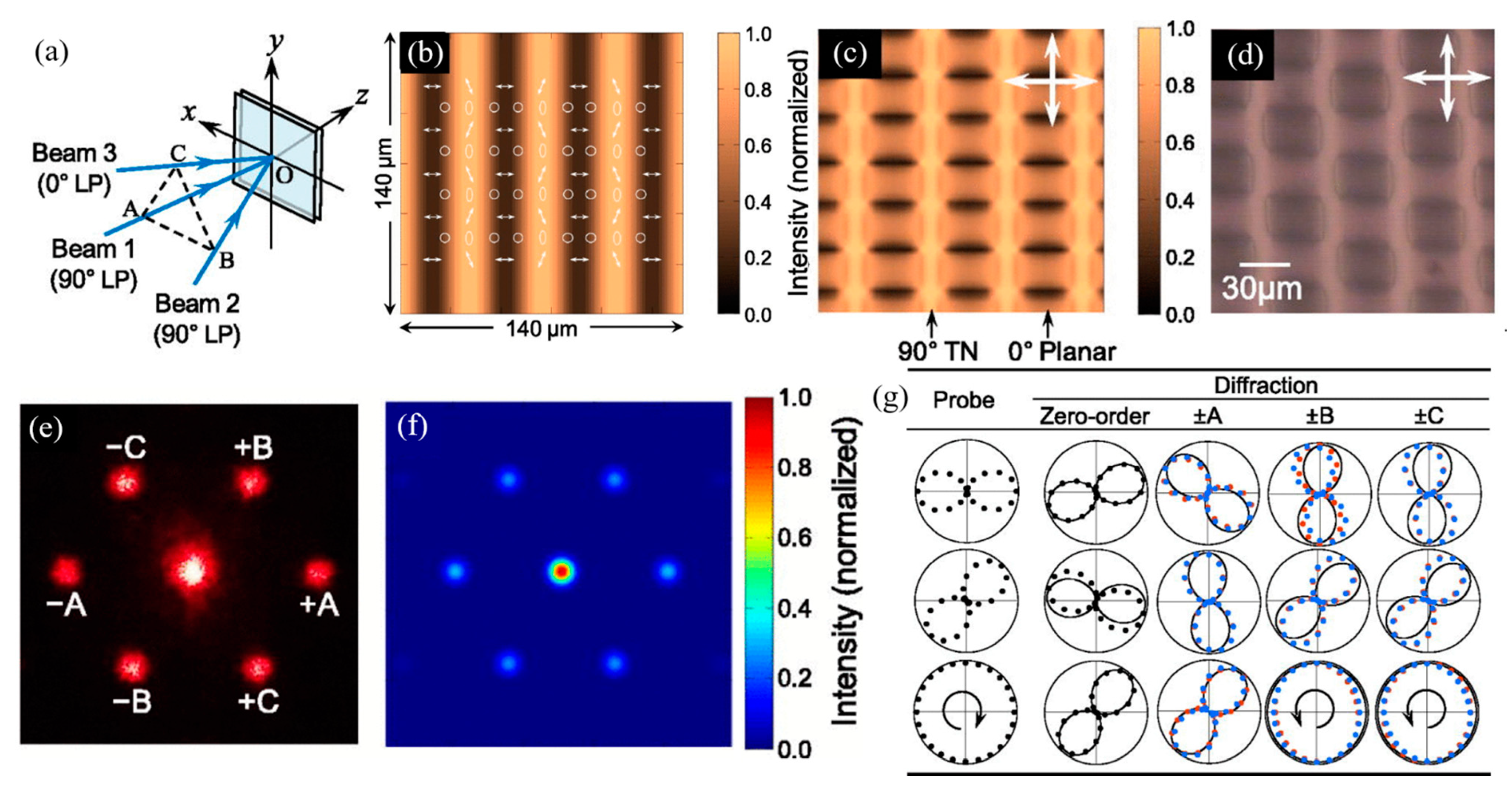
In 2016, a 2D PG was designed by H. Ono et al. using a photo-cross-linkable polymer LC with 4-(4-methoxycinnamoyloxy)biphenyl side groups (P6CB) as the alignment layer [36,37]. The alignment direction of P6CB can be controlled by the exposure energy of LP UV light. When the exposure energy is low, mesogenic groups align perpendicularly to the LP UV polarization azimuth after annealing. When the exposure energy is high, mesogenic groups align parallelly. Based on this feature, a 2D LC PG was designed based on the one-step exposure of a three-beam interference, where one beam is LP and the other two are LP with orthogonal polarization, as shown in Figure 5a. The intensity and polarization states of the interference field are modulated as shown in Figure 5b, where the intensity visibility is set at 0.67. Due to the absorption of the top P6CB layer, the alignments of the top and bottom layers are parallel and orthogonal alternatively in the high- and low-intensity areas by choosing a proper exposure time, giving an alternative planar and TN alignment. Here, a large grating period Λ was applied to suppress the large elastic-free energy, giving a 3D modulated anisotropic structure (Figure 5c,d). Seven diffraction spots were observed in both the experiment and simulation (Figure 5e,f). The polarization state varies with both the diffracted position and incident polarization, as shown in Figure 5g. However, this 2D grating does not have polarization selectivity property, where the diffraction states of the positive and negative orders are the same.
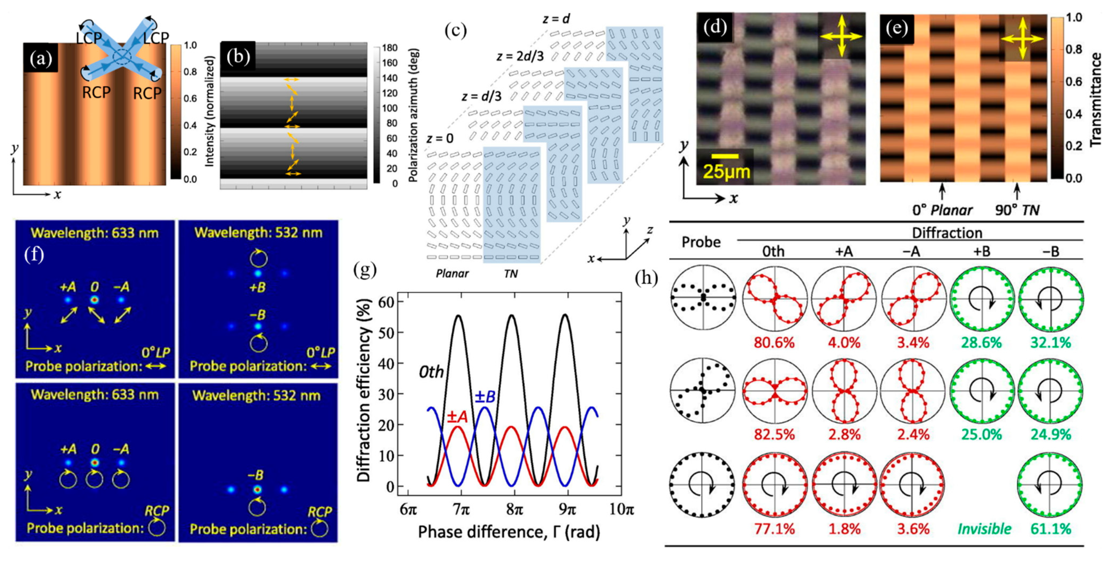
One year later, H. Ono et al. reported another 2D LC PG based on the one-step interference of four CP beams using the same photoalignment material and strategy [38,39]. Beams 1 and 3 are LCP on the top, and beams 2 and 4 are RCP at the bottom, as shown in Figure 6a. The polarization states of the interference field are periodically modulated along the y-axis, while the intensity is modulated sinusoidally along the x-axis, as shown in Figure 6b. In order to set the intensity visibility of the interference field as less than 1, the intensity of beams 1 and 2 to beams 3 and 4 was 9:1. Therefore, the LC cell has planar and TN alignment along x-axis in additional to the polarization modulation along the y-axis (Figure 6c), giving a 2D-modulated LC texture, as shown in Figure 6d,e. The simulated diffraction efficiency depends on the phase retardation Γ, where the diffraction spots along the x-axis (±A) and y-axis (±B) show a reverse-phase dependence (Figure 6f,g). The polarization selectivity was demonstrated as shown in the polar plot of Figure 6h. The LP probe beam is diffracted into 0th and ±A orders with orthogonal linear polarizations and ±B orders with orthogonal circular polarizations, while the CP probe beam is diffracted into 0th and ±A orders with the same circular polarization and one of the B orders with orthogonal circular polarization. In the experiment, the diffraction property was probed with a 633-nm and a 532-nm wavelength laser with proper cell thickness or by tuning the temperature to achieve phase retardation at the full-wave and half-wave conditions, respectively [37,38,39]. The experimental results showed good agreement with the simulation (Figure 6h).
Although the above investigations by H. Ono et al. applied multi-beam interferometry, they used P6CB as the alignment layer to achieve alternative parallel and perpendicular alignments on the two substrates based on the intensity modulation. Therefore, the LCs have alternative planar and TN alignments, and they are, in principle, a mixed case of 1D PG with a cross-assembling configuration, which is different from the traditional multi-beam holography.
3.2. 2D PGs Based on Multi-Beam Interference
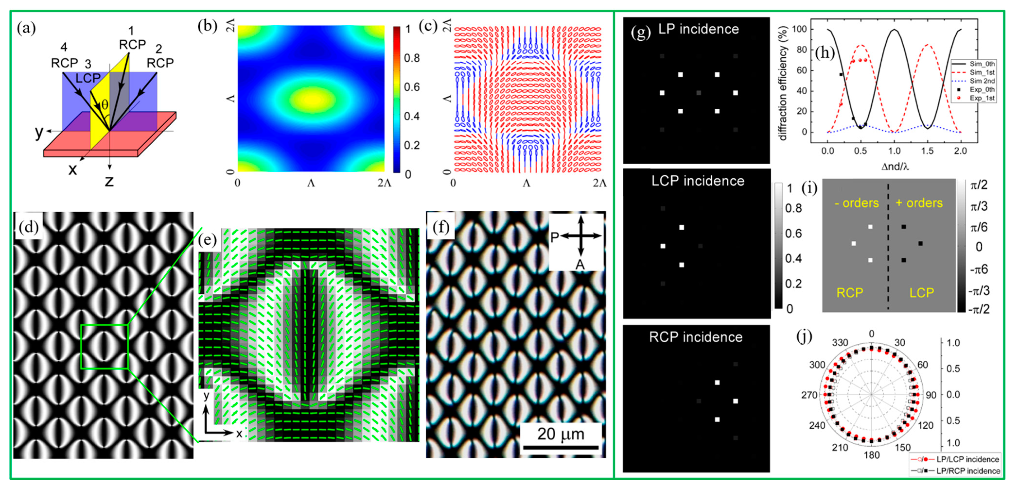
The multi-beam interference method has been widely applied for holographic lithography to fabricate 2D and 3D photonic crystals based on intensity modulation [40,41,42,43]. Adopting different polarization configurations, multi-beam interference was also used for 2D PG fabrication. In 2006, Crawford et al. reported a 2D PG based on the interference of four p-polarized beams [44]. In this configuration, the polarization state modulates in the 2D plane, as shown in Figure 7a. Azo-dye-doped LC was used for polarization direction recording, where the azo-dye molecules aligned perpendicular to the local polarization direction of light and forced the LC molecules to align in the same way (Figure 7b). According to this configuration, the LC texture observed by POM should be a regular checkerboard pattern, as depicted in Figure 7c. The observed LC texture is shown in Figure 7d. This 2D structure did show a 2D diffraction pattern with polarization dependency, where the intensity of the diffracted light varied with the incident polarizations (Figure 7e–g). However, the incident energy was mainly focused on the 0th order, and the diffraction efficiency on the 1st order was low. This is probably due to the imperfect orientation of the LCs caused by intensity modulation. As shown in Figure 7a, zero intensity areas exist in the multi-beam interference field; thus, there are polarization information losses at these areas, resulting in the imperfect orientation of azo-dye-doped LC.
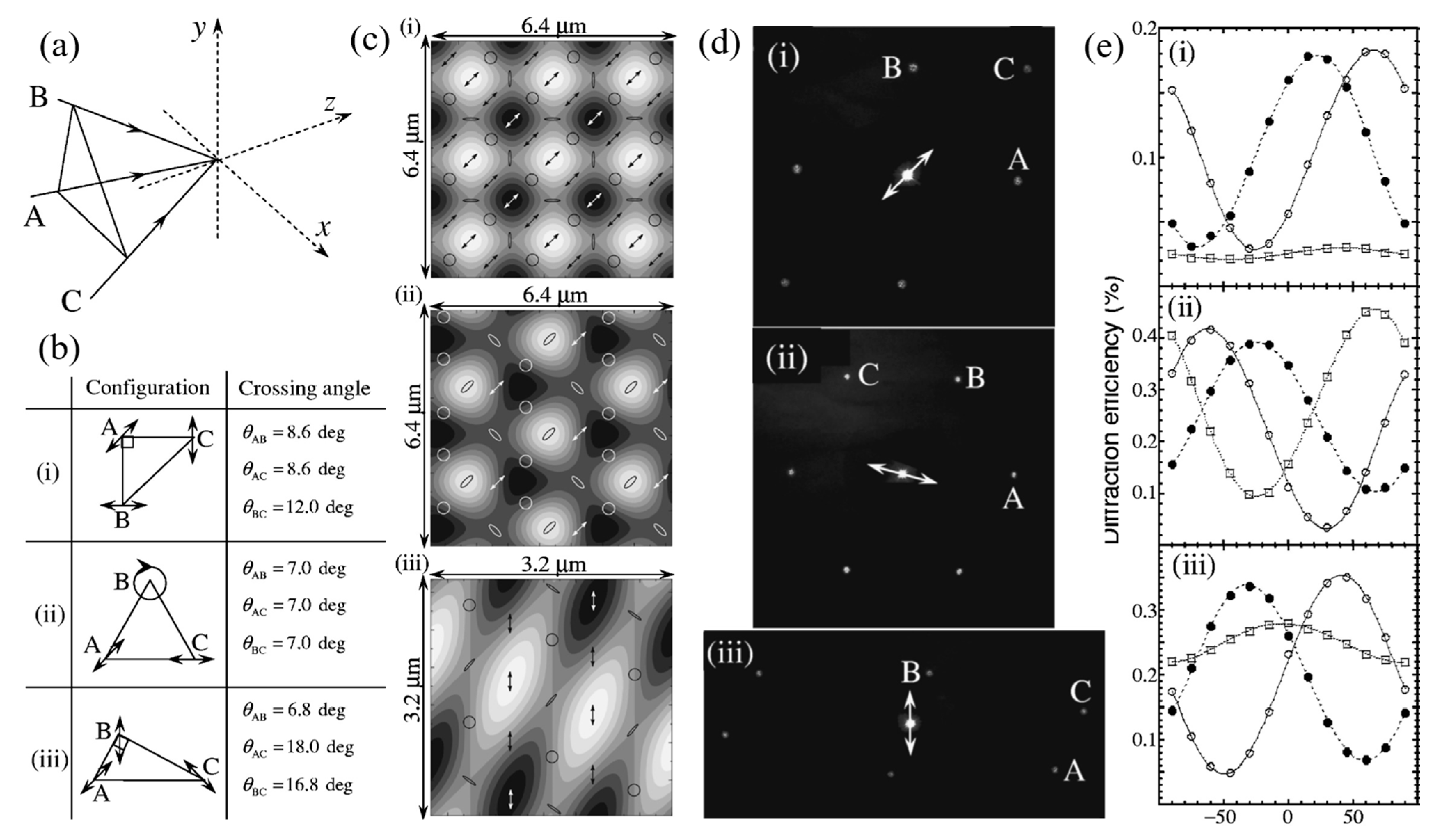
In addition to the imperfect orientation of photosensitive material at the zero intensity areas, the intensity modulation of the multi-beam polarization holography could cause topological relief in addition to the 2D polarization structure when photosensitive polymers are applied. H. Ono et al. reported an anisotropic photonic grating formed in photo-cross-linkable polymer LC using the three-beam interferometry of different polarization configurations in 2006 (Figure 8) [45]. The interference gave both intensity and polarization modulations. On the one hand, the polarization modulation resulted in an axis-selective photochemical reaction, giving LC director reorientation. On the other hand, the surface relief happened as a result of intensity modulation. The LC directors also tended to reorient along the migration direction due to the molecular migration during the surface relief formation process. Therefore, the diffraction was complexed in this case, and the diffraction efficiency stayed low.
To suppress the intensity modulation of the multi-beam interference, G. Cipparrone introduced relative phases into four interferential CP beams using a spatial light modulator [46]. A phase difference of π/2 between each consecutive beam was applied to two pairs of orthogonal LP or CP beams. In both cases, the light intensity modulation was suppressed, and 2D pure polarization microstructures were obtained, as shown in Figure 9a,d. The 2D polarization patterns were recorded by photosensitive side-chain polymethacrylic copolymer material, whose photoinduced linear birefringence was stronger compared to the circular birefringence under a low radiation dose [47]. The experimental diffractions showed good agreement with the theoretical previsions, as shown in Figure 9b-f. The diffraction of the 2D PG fabricated by orthogonally CP beams showed polarization dependence and selectivity, as expected. In the same year, the same group reported several complex 2D periodic chiral structures based on the same design but a large radiation dose, where the circular birefringence rose more prominently to show both linear and circular photoinduced anisotropies [48]. Interesting supramolecular chiral structures and complex 2D grating diffraction were obtained as a result. However, the usage of a polymer made the grating untunable by the external field, and the photoinduced birefringence was on the order of 10−3, which was too low to give a high diffraction efficiency.
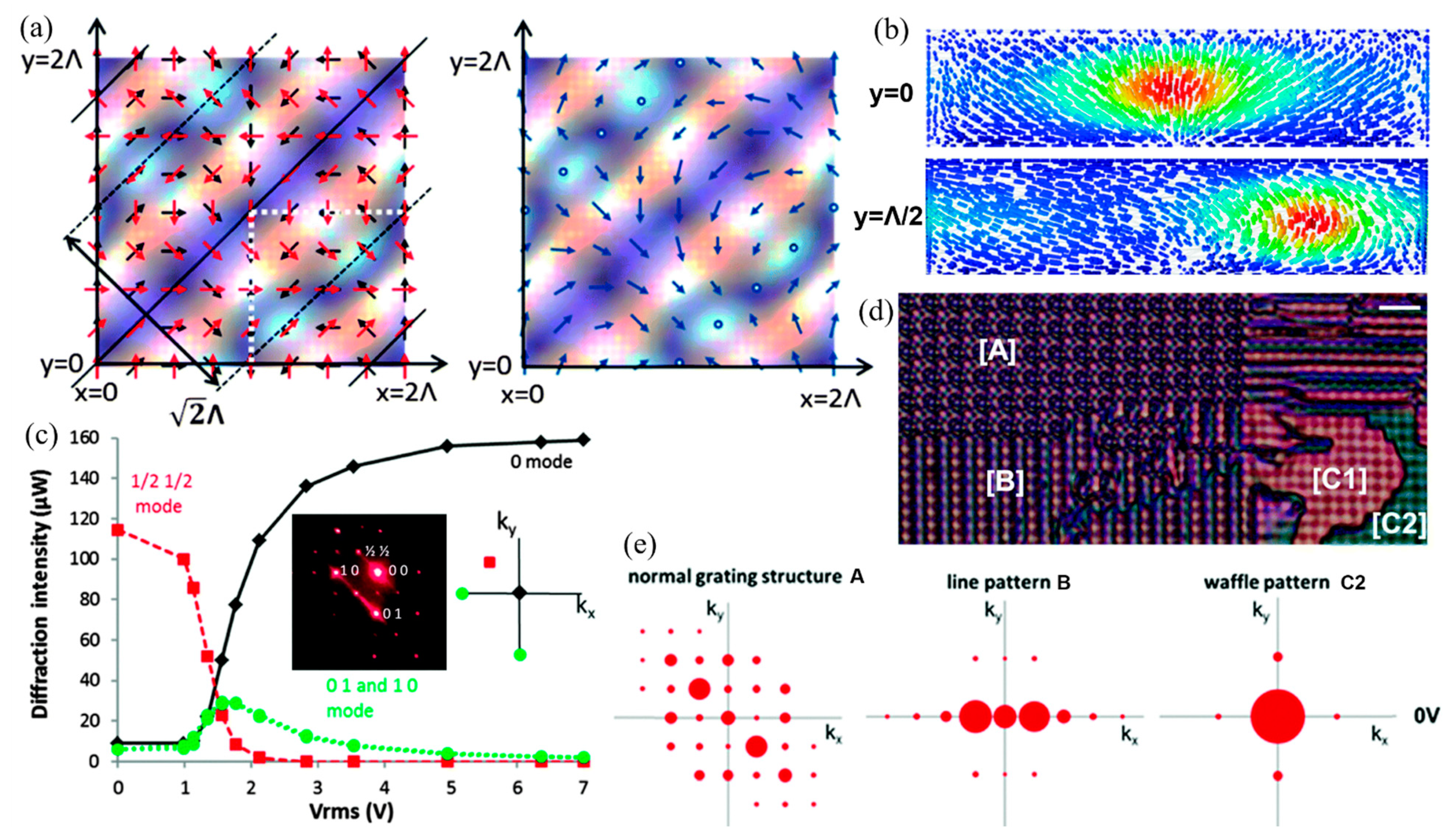
In 2018, Y. Shi et al. discussed both the intensity and polarization distributions of the interference of four symmetrically arranged CP beams (Figure 10a). The four beams had the same intensities and no relative phase differences [49]. The interference field had intensity modulations, while only the case with one CP beam and three orthogonally CP beams did not have zero intensity areas (Figure 10b). In this case, the interference polarization was generally EP and modulated in the 2D plane, where the polarization ellipticity and orientation gradually varied with the position, as shown in Figure 10c. An azobenzene sulfonic dye, SD1, was chosen as the photoalignment material [14]. When it is exposed to LP or EP light, the azobenzene molecules align perpendicularly to the polarization direction or the longitudinal direction of the polarization ellipse [50,51]. In a stable environment, the alignment quality is saturated with an increasing exposure dosage [52]. Thus, as long as there are no null intensity areas, the photoalignment layer could be fully patterned, regardless of the modulated intensity. Moreover, the LC disclination lines were avoided in this case, since the polarization orientation gradually changed in the 2D plane, giving a well-defined LC distribution. Therefore, a periodic 2D pure polarization structure with intrinsic chiral property was obtained by photoaligned LC, as shown in Figure 10d–f.
The diffraction property of the 2D PG was simulated based on Fourier transform and a Jones matrix, giving a 2D diffraction pattern, as shown in Figure 10g. The maximum diffraction efficiency happened at the half-wave conditions, where the 1st orders of (±1,0), (±1, ±1) occupied about 85% of the total energy based on the simulation. The experiment gave ~70% diffraction efficiency on the 1st order (Figure 10h), where the reduction was mainly due to the misalignment of the interference setup. The diffraction had polarization sensitivity, as expected. The +1st and −1st orders were generally CP with opposite helicities, occupying half the space, respectively, as shown in Figure 10i, while the 0th order kept the polarization of the incidence. When the incident light was CP, the diffracted light was CP with opposite helicity, mainly occupying half of the space (Figure 10g). In this work, the authors noticed that the diffracted CP light had a weak energy leakage to the opposite side with a contrast ratio of 1/79. This was probably because the photoalignment layer could only record the polarization orientation instead of the complete polarization information. However, since the energy leakage was very weak, the ellipticity of the diffracted beam was near 1, still giving good CPL quality (Figure 10j). Moreover, electrically tunable 2D LC PG was also demonstrated using photoaligned LC in a cell. Therefore, reconciling both the intensity coverage and polarization distribution of the multi-beam interference field, the fabricated 2D LC PG showed superior diffraction property.
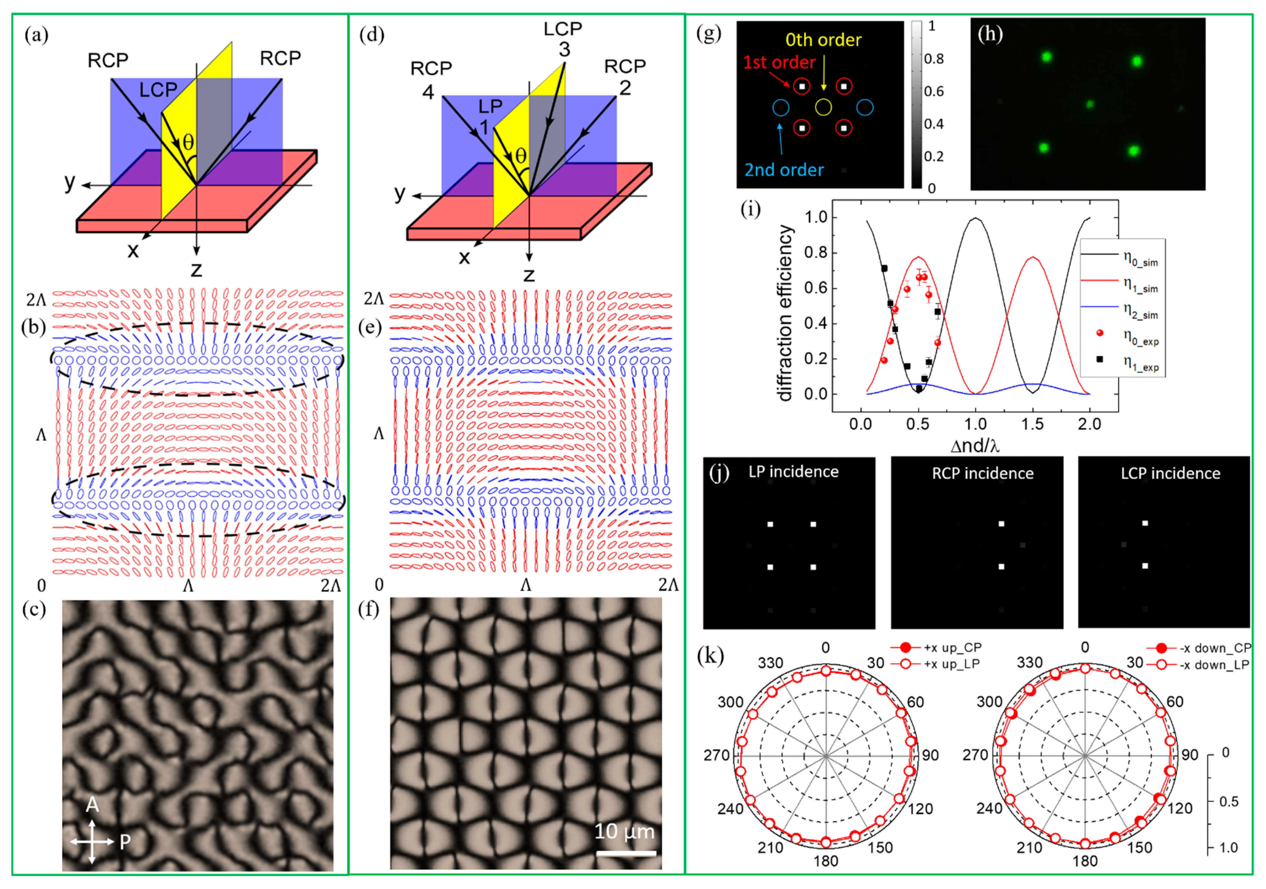
One year later, the same group reported another 2D LC PG based on a similar strategy [53]. Three-beam CPL interference gave full light intensity coverage, but the polarization directions had sudden changes (Figure 11a,b). Therefore, the fabrication of photoaligned 2D LC PG based on this interference configuration was not feasible due to the large elastic energy requirement of LC. The defects and disclination lines could not be avoided, as shown in Figure 11c. To solve this problem, a weak LP beam was introduced into the three-CP beam interference configuration (Figure 11d). The introduction modified the polarization distribution of the interference field, helping to give well-defined LC directors (Figure 11e,f). Meanwhile, the LP light introduction gave two additional diffraction spots (marked as the 2nd order in Figure 11g) in addition to the original four spots on the 1st order and caused more energy leakage, lowering both the diffraction efficiency and the ellipticity of the diffracted light. However, the study showed that the disturbance was weak as long as the introduced LP light intensity was kept low. In their design, the LP light intensity was chosen to be one-fifth of the other CP light to give a well-defined LC alignment and good diffraction property (Figure 11h). The maximum diffraction of the 1st order occupied about 77% of the total energy at the half-wave conditions, with the polarization selectivity similar to the previous work [49] (Figure 11i,j). The ellipticities of the diffracted beams were near 1, indicating good CPL qualities (Figure 11k). Therefore, the weak light introduction method provided a strategy for the 2D LC PG design based on multi-beam interference in order to satisfy the critical fabrication requirements of both the intensity coverage and polarization distribution.
As discussed above, the fabrication of 2D PG based on multi-beam interference needs to satisfy the critical fabrication requirements of both the intensity coverage and continuous orientation distribution of the polarization states. These are hard guaranteed at the same time in most multi-beam interference cases. In addition, the designs of 2D PGs, either by assembling two 1D polarization patterns or based on the multi-beam interference method, are always limited by the light interference. If a 2D polarization pattern with superior diffraction property could be designed alone, more 2D PGs may be obtained with the help of a digital micro-mirror device (DMD) [54] or direct laser writing system [55], which are capable of creating arbitrary LC patterning.
4. Micro-Pixelated LC Structures
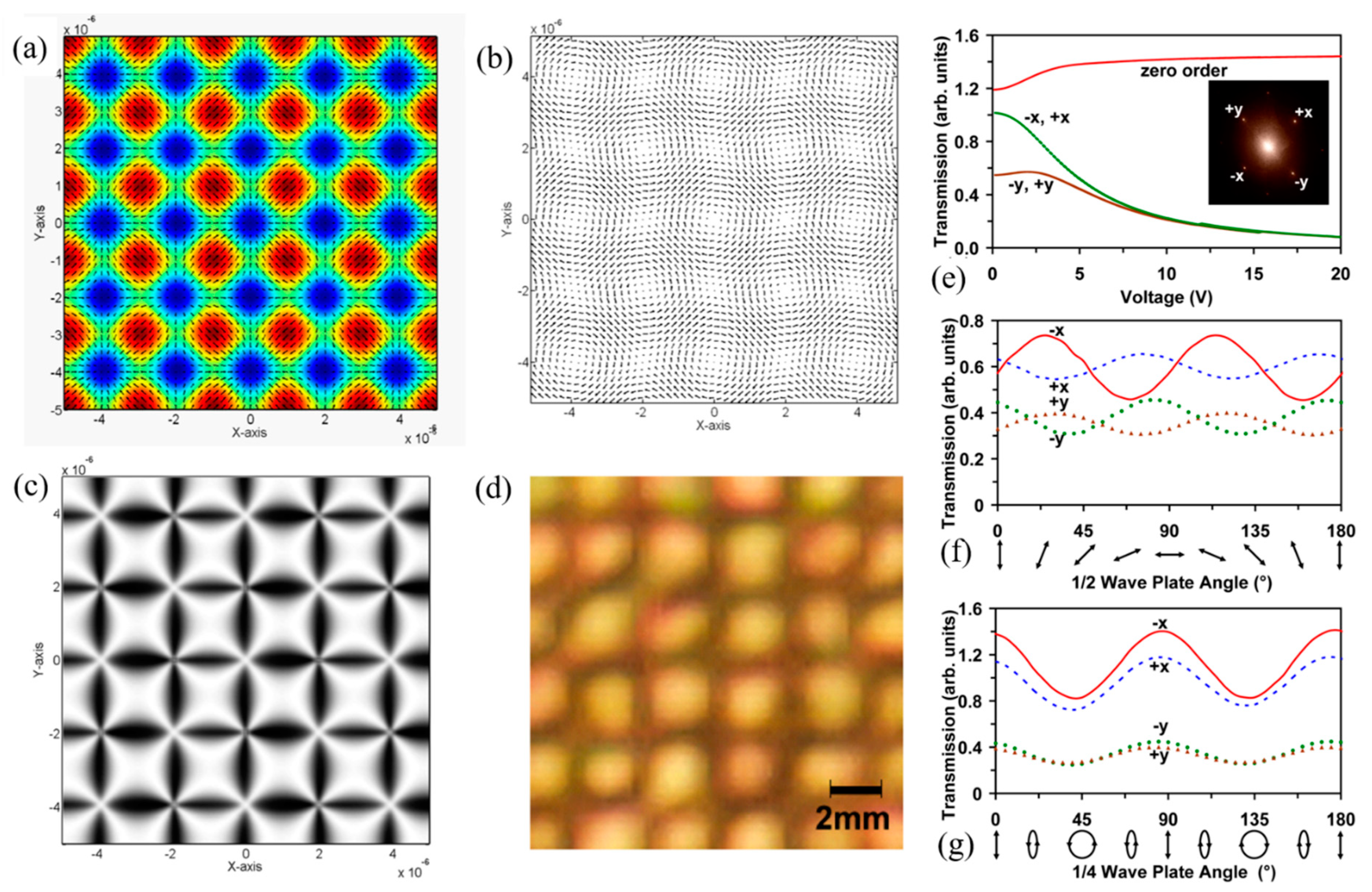
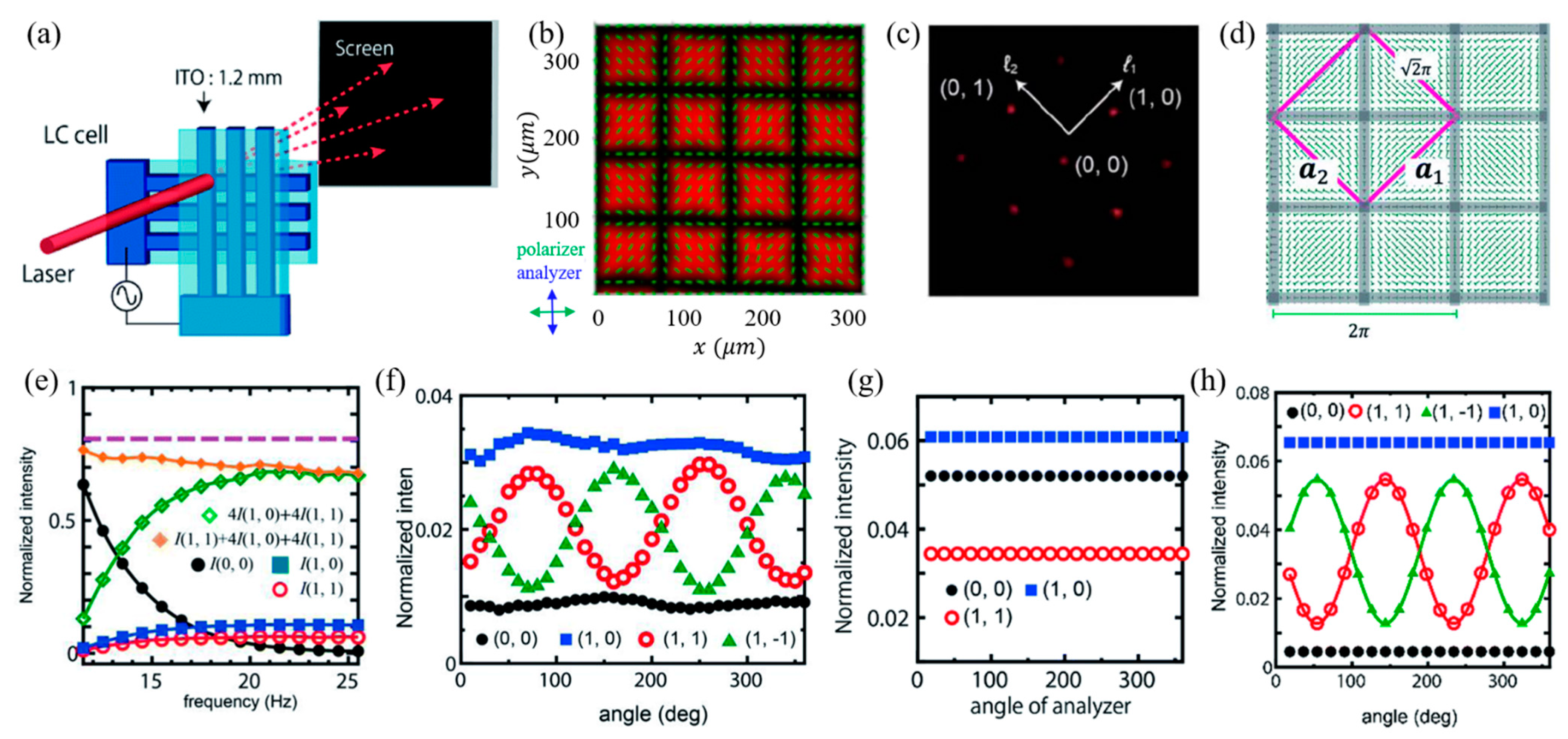
In addition to the 2D PGs fabricated based on polarization-sensitive materials, Y. Sasaki et al. reported a tunable 2D PG obtained from a micro-pixelated LC structure in 2018 [56,57]. By applying a micro-pixelated electric field to a homeotropically aligned nematic LC with negative dielectric anisotropy and ionic additives, as designed in Figure 12a, umbilical defects were formed, and a square array of a 2D micropattern was self-organized (Figure 12b). The LC directors in the 2D plane resemble the polarization pattern of Figure 7a but with a much better LC orientation. The 2D diffraction pattern is shown in Figure 12c. The diffraction spot (l1, l2) is defined as l1b1+l2b2, where biis the primitive reciprocal vector related to the primitive cell vector of ai as aibj=2πδij (Figure 12d). Since the LC orientation changes from homeotropic to tilted with the electric field frequency at a fixed voltage, the diffraction efficiency exhibits frequency dependence (Figure 12e). When the LC phase retardation reaches the half-wave conditions, the 0th-order diffraction is minimized, and the surrounding eight spots of (±1, 0), (0, ±1), (±1, ±1) and (±1, ∓1) reach the highest diffraction efficiency of 87%. This reported value is much higher than the observation in Reference [44] with similar LC configurations, due to the well-defined LC orientation. This diffraction efficiency is similar to the 2D LC PG as reported in Reference [49] but higher than that of the electrically tunable device in LC cells, since this 2D micropattern not only avoids the mismatch problem of the photoalignment pattern on the two substrates but also avoids the undefined pretilt angle, which becomes severer with the applied electric field.
However, the diffraction pattern stayed the same regardless of the polarization incident, showing no polarization selectivity. This is because the grid-like pattern belongs to the 2D space group of P4m, limited by the micro-pixelated design without a chiral structure. On the other hand, the polarization state was found to change with the diffraction position (Figure 12f). The polarization conversion happens on (±1, 0) and (0, ±1) orders, since the LC behaves as a half-wave plate whose optical axis is directed toward the origin. The diffracted beams on the (±1, ±1) and (±1, ∓1) orders exhibit modulated EP with CP incidence. This phenomenon is different from the case of 2D photopatterned LC with constant phase retardation, where the diffracted polarization is the same as the incidence (Figure 12g). The analysis showed that, when the birefringence modulation of the unevenly tilted LC with umbilical defects, as shown in Figure 12d, was taken into account, the diffraction gave modulated polarization states, as shown in Figure 12h.
5. Potential Applications
As discussed above, the 2D PGs could distribute an optical signal into multiple channels with high efficiency and selectivity by the polarization control. This feature is essential for applications in optical communications, quantum computing and optical security industries [2,3,4,5]. In addition, the PGs have been demonstrated to be an excellent candidate for nonmechanical beam steering devices [23]. By combining two 1D PGs in orthogonal directions with a quarter-wave plate inserted in between, a 2D beam deflector was demonstrated [58]. It is compact and lightweight compared to other spatial light modulators, such as LC on silicon and DMD. However, this design still needs at least three optical elements. The 2D PG provides great potentiality for 2D nonmechanical beam steering with a single optical element. The compactness makes it competitive for applications in augmented reality (AR) and virtual reality (VR) systems, where multiple diffraction angles are necessary for eye tracking and EyeBOX enlarging [58,59].
Moreover, 2D photonic crystals and microstructures have shown tailored and extraordinary properties for various applications [40,41,42,43]. With an intrinsic chiral property, the complex 2D polarization structures make them excellent candidates for chiral microstructure fabrication [48], offering the additional features of optical activity and circular dichroism [60,61]. In addition, the novel 2D structure used in an imaging system could also be applied for metamaterial fabrication as a template for mask-free photolithography [62]. Although the current structures are on a micron scale, they may be extended to different scales for metamaterial fabrication in terahertz, infrared and even visible bands.
6. Conclusions
PGs with high diffraction efficiency and polarization selectivity provide great potential for polarization beam splitting and manipulation. In particular, the 2D PG offers an effective approach to selectively distribute an optical signal into multiple channels by polarization control, therefore attracting much attention. The 2D polarization structures also make them excellent candidates for microstructure and metamaterial fabrications. The design based on LC with tunable optical anisotropy provides a great opportunity for 2D PG fabrication. Several 2D LC PGs have been obtained in the past two decades by assembling two 1D polarization patterns, multi-beam polarization interference and a micro-pixelated electric field. A diffraction efficiency of ~90% has been realized. However, shortcomings still exist in some designs. Therefore, more 2D PGs with a high diffraction efficiency, polarization selectivity and precise position control are still in demand.
Author Contributions
Y.S., D.L. and K.Z. participated in the manuscript preparation. All authors have read and agreed to the published version of the manuscript.
Funding
This study received financial support by the National Natural Science Foundation of China (NSFC) (62005136), Natural Science Foundation of Zhejiang Province (LY21E030003) and Shenzhen Science and Technology Innovation Council (JCYJ20180305180611745).
Conflicts of Interest
The authors declare no conflict of interest.
References
- Matranga, A.; Baig, S.; Boland, J.; Newton, C.; Taphouse, T.; Wells, G.; Kitson, S. Biomimetic reflectors fabricated using self-organising, self-aligning liquid crystal polymers. Adv. Mater. 2013, 25, 520–523. [Google Scholar] [CrossRef] [PubMed]
- Eckhardt, S.; Bruzzone, C.; Aastuen, D.; Ma, J. 3M PBS for high performance LCOS optical engine. Proc. SPIE 2003, 5002, 106–110. [Google Scholar]
- Yeralan, S.; Gunther, J.; Ritums, D.L.; Cid, R.; Popovich, M.M. Switchable Bragg grating devices for telecommunications applications. Opt. Eng. 2002, 41, 1774–1779. [Google Scholar] [CrossRef]
- Stenholm, S. Polarization coding of quantum information. Opt. Commun. 1996, 123, 287–296. [Google Scholar] [CrossRef]
- Lim, Y.L.; Beige, A.; Kwek, L.C. Repeat-until-success linear optics distributed quantum computing. Phys. Rev. Lett. 2005, 95, 030505. [Google Scholar] [CrossRef] [Green Version]
- Davis, J.A.; Adachi, J.; Fernández-Pousa, C.R.; Moreno, I. Polarization beam splitters using polarization diffraction gratings. Opt. Lett. 2001, 26, 587–589. [Google Scholar] [CrossRef]
- Kim, J.; Komanduri, R.K.; Lawler, K.F.; Jason Kekas, D.; Escuti, M.J. Efficient and monolithic polarization conversion system based on a polarization grating. Appl. Opt. 2012, 51, 4852–4857. [Google Scholar] [CrossRef] [PubMed] [Green Version]
- Kim, J.-H.; Yoneya, M.; Yamamoto, J.; Yokoyama, H. Nanosurfaces of a liquid crystal alignment layer by an atomic force microscope: A detailed characterization. Nanotechnology 2002, 13, 133–137. [Google Scholar] [CrossRef]
- Kim, J.; Na, J.-H.; Lee, S.-D. Fully continuous liquid crystal diffraction grating with alternating semi-circular alignment by imprinting. Opt. Express 2012, 20, 3034. [Google Scholar] [CrossRef]
- Schadt, M.; Schmitt, K.; Kozinkov, V.; Chigrinov, V. Surface-induced parallel alignment of liquid crystals by linearly polymerized photopolymers. Jpn. J. Appl. Phys. 1992, 31, 2155–2164. [Google Scholar] [CrossRef]
- Hasegawa, M.; Taira, Y. Nematic homogeneous photo alignment by polyimide exposure to linearly polarized UV. J. Photopolym. Sci. Technol. 1995, 8, 241–248. [Google Scholar] [CrossRef] [Green Version]
- Ichimura, K.; Suzuki, Y.; Seki, T.; Hosoki, A.; Aoki, K. Reversible change in alignment mode of nematic liquid crystals regulated photochemically by command surfaces modified with an azobenzene monolayer. Langmuir 1988, 4, 1214–1216. [Google Scholar] [CrossRef]
- Gibbons, W.M.; Shannon, P.J.; Sun, S.T.; Swetlin, B.J. Surface-mediated alignment of nematic liquid crystals with polarized laser light. Nature 1991, 351, 49–50. [Google Scholar] [CrossRef]
- Chigrinov, V.; Pikin, S.; Verevochnikov, A.; Kozenkov, V.; Khazimullin, M.; Ho, J.; Huang, D.D.; Kwok, H.S. Diffusion model of photoaligning in azo-dye layers. Phys. Rev. E 2004, 69, 061713. [Google Scholar] [CrossRef] [PubMed] [Green Version]
- Crawford, G.P.; Eakin, J.N.; Radcliffe, M.D.; Callan-Jones, A.; Pelcovits, R.A. Liquid-crystal diffraction gratings using polarization holography alignment techniques. J. Appl. Phys. 2005, 98, 123102. [Google Scholar] [CrossRef] [Green Version]
- Presnyakov, V.; Asatryan, K.; Galstian, T.; Chigrinov, V. Optical polarization grating induced liquid crystal micro-structure using azo-dye command layer. Opt. Express 2006, 14, 10558–10564. [Google Scholar] [CrossRef]
- Escuti, M.J.; Jones, W.M. A polarization-independent liquid crystal spatial light modulator. Proc. SPIE 2006, 6332, 63320M. [Google Scholar]
- Gori, F. Measuring Stokes parameters by means of a polarization grating. Opt. Lett. 1999, 24, 584–586. [Google Scholar] [CrossRef]
- Tervo, J.; Turunen, J. Paraxial-domain diffractive elements with 100% efficiency based on polarization gratings. Opt. Lett. 2000, 25, 785–786. [Google Scholar] [CrossRef]
- Xiang, X.; Kim, J.; Komanduri, R.; Escuti, M.J. Nanoscale liquid crystal polymer bragg polarization gratings. Opt. Express 2017, 25, 19298–19308. [Google Scholar] [CrossRef] [PubMed] [Green Version]
- Yin, K.; Lee, Y.H.; He, Z.; Wu, S.T. Stretchable, flexible, rollable, and adherable polarization volume grating film. Opt. Express 2019, 27, 5814–5823. [Google Scholar] [CrossRef]
- Oh, C.; Escuti, M.J. Achromatic diffraction from polarization gratings with high efficiency. Opt. Lett. 2008, 33, 2287. [Google Scholar] [CrossRef]
- Kim, J.; Oh, C.; Escuti, M.J.; Hosting, L.; Serati, S. Wide-angle nonmechanical beam steering using thin liquid crystal polarization gratings. Proc. SPIE 2008, 7093, 709302. [Google Scholar]
- McManamon, P.F.; Bos, P.J.; Escuti, M.J.; Heikenfeld, J.; Serati, S.; Xie, H.; Watson, E.A. A review of phased array steering for narrow-band electrooptical systems. Proc. IEEE 2009, 97, 1078–1096. [Google Scholar] [CrossRef]
- Goldenberg, L.M.; Lisinetskii, V.; Gritsai, Y.; Stumpe, J.; Schrader, S. First observation of DFB lasing in polarization gratings written in azobenzene film. Laser Phys. Lett. 2013, 10, 085804. [Google Scholar] [CrossRef]
- Du, T.; Fan, F.; Tam, A.M.W.; Sun, J.T.; Chigrinov, V.G.; Kwok, H.S. Complex nanoscale-ordered liquid crystal polymer film. for high transmittance holographic polarizer. Adv. Mater. 2015, 27, 7191–7195. [Google Scholar] [CrossRef]
- Chen, P.; Wei, B.-Y.; Hu, W.; Lu, Y.-Q. Liquid-crystal-mediated geometric phase: From transmissive to broadband reflective planar optics. Adv. Mater. 2019, 32, 1903665. [Google Scholar] [CrossRef]
- Shi, Y.; Lai, Y.; Li, Y.; Liu, Y.J.; Chigrinov, V.G.; Kwok, H.S.; Luo, D.; Sun, X.W. Circularly polarised lasing from all-solid organic semiconductor activated external distributed feedback based on polarisation grating. Liq. Cryst. 2020, 48, 1186–1193. [Google Scholar] [CrossRef]
- Lin, T.; Xie, J.; Zhou, Y.; Zhou, Y.; Yuan, Y.; Fan, F.; Wen, S. Recent Advances in Photoalignment Liquid Crystal Polarization Gratings and Their Applications. Crystals 2021, 11, 900. [Google Scholar] [CrossRef]
- Provenzano, C.; Pagliusi, P.; Cipparrone, G. Electrically tunable two-dimensional liquid crystals gratings induced by polarization holography. Opt. Express 2007, 15, 5872–5878. [Google Scholar] [CrossRef] [PubMed]
- Li, S.Z.; Zhao, Z.W.; Wang, C.M.; Wang, Q.D.; Yao, L.; Peng, Z.H.; Liu, Y.G.; Xuan, L. Electrically tunable photo-aligned two-dimensional liquid crystal polarisation grating. Liq. Cryst. 2019, 46, 1175–1182. [Google Scholar] [CrossRef]
- Wu, W.Y.; Li, M.S.; Lin, H.C.; Fuh, A.Y.G. Two-dimensional holographic polarization grating formed on azo-dye-doped polyvinyl alcohol films. J. Appl. Phys. 2008, 103, 083119. [Google Scholar] [CrossRef]
- Wang, M.F.; Li, Y.N.; Yokoyama, H. Artificial web of disclination lines in nematic liquid crystals. Nat. Commun. 2017, 8, 388. [Google Scholar] [CrossRef] [PubMed] [Green Version]
- Nys, I.; Beeckman, J.; Neyts, K. Switchable 3D liquid crystal grating generated by periodic photo-alignment on both substrates. Soft Matter. 2015, 11, 7802–7808. [Google Scholar] [CrossRef]
- Nys, I.; Nersesyan, V.; Beeckman, J.; Neyts, K. Complex liquid crystal superstructures induced by periodic photo-alignment at top and bottom substrate. Soft Matter. 2018, 14, 6892–6902. [Google Scholar] [CrossRef]
- Kawatsuki, N.; Goto, K.; Kawakami, T.; Yamamoto, T. Reversion of alignment direction in the thermally enhanced photoorientation of photo-cross-linkable polymer liquid crystal films. Macromolecules 2012, 35, 706–713. [Google Scholar] [CrossRef]
- Kawai, K.; Sakamoto, M.; Noda, K.; Sasaki, T.; Kawatsuki, N.; Ono, H. Three-dimensionally modulated anisotropic structure for diffractive optical elements created by one-step three-beam polarization holographic photoalignment. J. Appl. Phys. 2016, 119, 123102. [Google Scholar] [CrossRef]
- Kawai, K.; Sakamoto, M.; Noda, K.; Sasaki, T.; Kawatsuki, N.; Ono, H. Liquid crystal gratings for advanced control of polarized light propagation fabricated by one-step multiple beam holographic photoalignment. Proc. SPIE 2017, 10125, 101251I. [Google Scholar]
- Kawai, K.; Sakamoto, M.; Noda, K.; Sasaki, T.; Kawatsuki, N.; Ono, H. Tunable dichroic polarization beam splitter created by one-step holographic photoalignment using four-beam polarization interferometry. J. Appl. Phys. 2017, 121, 013102. [Google Scholar] [CrossRef]
- Campbell, M.; Sharp, N.D.; Harrison, T.M. Fabrication of photonic crystals for the visible spectrum by holographic lithography. Nature 2000, 6773, 53. [Google Scholar] [CrossRef]
- Escuti, M.J.; Qi, J.; Crawford, G.P. Holographic photonic crystals. Opt. Eng. 2004, 43, 1973. [Google Scholar]
- Liu, Y.J.; Sun, X.W. Electrically tunable two-dimensional holographic photonic crystal fabricated by a single diffractive element. Appl. Phys. Lett. 2006, 89, 171101. [Google Scholar] [CrossRef]
- Luo, D.; Sun, X.W.; Dai, H.T.; Liu, Y.J.; Yang, H.Z.; Ji, W. Two-directional lasing from a dye-doped two-dimensional hexagonal photonic crystal made of holographic polymer-dispersed liquid crystals. Appl. Phys. Lett. 2009, 95, 151115. [Google Scholar] [CrossRef]
- Gorkhali, S.P.; Cloutier, S.G.; Crawford, G.P. Two-dimensional vectorial photonic crystals formed in azo-dye-doped liquid crystals. Opt. Lett. 2006, 31, 3336–3338. [Google Scholar] [CrossRef]
- Ono, H.; Emoto, A.; Kawatsuki, N. Anisotropic photonic grating formed in photocross-linkable polymer liquid crystals. J. Appl. Phys. 2006, 100, 013522. [Google Scholar] [CrossRef]
- Ruiz, U.; Provenzano, C.; Pagliusi, P.; Cipparrone, G. Pure two-dimensional polarization patterns for holographic recording. Opt. Lett. 2012, 37, 311–313. [Google Scholar] [CrossRef]
- Cipparrone, G.; Pagliusi, P.; Provenzano, C.; Shibaev, V.P. Reversible photoinduced chiral structure in amorphous polymer for light polarization control. Macromolecules 2008, 41, 5992. [Google Scholar] [CrossRef]
- Ruiz, U.; Pagliusi, P.; Provenzano, C.; Shibaev, V.P.; Cipparrone, G. Supramolecular chiral structures: Smart polymer organization guided by 2d polarization light patterns. Adv. Funct. Mater. 2012, 22, 2964–2970. [Google Scholar] [CrossRef]
- Shi, Y.; Liu, Y.J.; Song, F.; Chigrinov, V.G.; Kwok, H.S.; Hu, M.; Luo, D.; Sun, X.W. Photoalignment-induced two-dimensional liquid crystal polarization structure via multi-beam polarization interferometry. Opt. Express 2018, 26, 7683–7692. [Google Scholar] [CrossRef] [PubMed]
- Sekkat, Z.; Knoll, W. Photoreactive Organic Thin Films; Academic Press: New York, NY, USA, 2002. [Google Scholar]
- Tan, L.; Ho, J.Y.; Kwok, H.S. 22.1: Binary alignment pattern induced by single step exposure of laser beam polarization interference. SID Dig. 2012, 43, 286–288. [Google Scholar] [CrossRef]
- Shi, Y.; Zhao, C.; Ho, J.Y.L.; Vashchenko, V.V.; Srivastava, A.K.; Chigrinov, V.G.; Kwok, H.S.; Song, F.; Luo, D. Exotic property of azobenzenesulfonic photoalignment material based on relative humidity. Langmuir 2017, 33, 3968–3974. [Google Scholar] [CrossRef] [PubMed]
- Shi, Y.; Lai, Y.; Liu, Y.J.; Chigrinov, V.G.; Kwok, H.S.; Hu, M.; Luo, D.; Sun, X.W. Two-dimensional liquid crystal polarization grating via linearly polarized light modified multi-beam polarization interferometry. Opt. Express 2019, 27, 13061–13071. [Google Scholar] [CrossRef] [PubMed]
- Wu, H.; Hu, W.; Hu, H.-C.; Lin, X.-W.; Zhu, G.; Choi, J.-W.; Chigrinov, V.; Lu, Y.-Q. Arbitrary photo-patterning in liquid crystal alignments using DMD based lithography system. Opt. Express 2012, 20, 16684–16689. [Google Scholar] [CrossRef] [Green Version]
- Miskiewicz, M.N.; Escuti, M.J. Direct-writing of complex liquid crystal patterns. Opt. Express 2014, 22, 12691–12706. [Google Scholar] [CrossRef]
- Salamon, P.; Éber, N.; Sasaki, Y.; Orihara, H.; Buka, Á.; Araoka, F. Tunable optical vortices generated by self-assembled defect structures in nematics. Phys. Rev. Appl. 2018, 10, 044008. [Google Scholar] [CrossRef] [Green Version]
- Amano, R.; Salmon, P.; Yokokawa, S.; Kobayashi, F.; Sasaki, Y.; Fujii, S.; Buka, A.; Araoka, F.; Orihara, H. Tunable two-dimensional polarization grating using a self-organized micropixelated liquid crystal structure. RSC Adv. 2018, 8, 41472–41479. [Google Scholar] [CrossRef] [Green Version]
- Lin, T.; Zhan, T.; Zou, J.; Fan, F.; Wu, S.-T. Maxwellian near-eye display with an expanded eyebox. Opt. Express 2020, 28, 38616–38625. [Google Scholar] [CrossRef] [PubMed]
- Chen, H.; Weng, Y.; Xu, D.; Tabiryan, N.V.; Wu, S.-T. Beam steering for virtual/augmented reality displays with a cycloidal diffractive waveplate. Opt. Express 2016, 24, 7287–7298. [Google Scholar] [CrossRef] [Green Version]
- Decker, M.; Ruther, M.; Kriegler, C.E.; Zhou, J.; Soukoulis, C.M.; Linden, S.; Wegener, M. Strong optical activity from twisted-cross photonic metamaterials. Opt. Lett. 2009, 34, 2501–2503. [Google Scholar] [CrossRef] [PubMed]
- Decker, M.; Klein, M.W.; Wegener, M.; Linden, S. Circular dichroism of planar chiral magnetic metamaterials. Opt. Lett. 2007, 32, 856–858. [Google Scholar] [CrossRef] [Green Version]
- Lee, C.-R.; Lin, S.-H.; Wang, S.-M.; Lin, J.-D.; Chen, Y.-S.; Hsu, M.-C.; Liu, J.-K.; Mo, T.-S.; Huang, C.-Y. Optically controllable photonic crystals and passively tunable terahertz metamaterials using dye-doped liquid crystal cells. J. Mater. Chem. C 2018, 6, 4959–4966. [Google Scholar] [CrossRef]
Figure 1.
(a) Structure of the 2D LC PG by cross-assembling two 1D polarization patterns. (b) Diffraction patterns with different incident polarizations. Reproduced with permission from Reference [30] © The Optical Society.
Figure 1.
(a) Structure of the 2D LC PG by cross-assembling two 1D polarization patterns. (b) Diffraction patterns with different incident polarizations. Reproduced with permission from Reference [30] © The Optical Society.

Figure 2.
(a) Structures of 2D LC PGs by assembling two 1D polarization patterns with crossing angle of π/2, 3π/4 and π, respectively. (b) Diffraction images of the corresponding structures from top to bottom with (left) LP, (middle) left CP (LCP) and right CP (RCP) incident beams. (c) The diffraction efficiency as a function of the applied ac voltage with a LCP probe beam for the sample with a π crossing angle. Reproduced from Reference [31] with permission from Taylor & Francis.

Figure 3.
(a) Simulated image of a 2D LC PG between crossed polarizers with a square web of disclinations. Diffraction pattern (b) and diffraction efficiency (c) with the applied ac voltage. (d) The square web of disclinations of LC observed by a polarized optical microscope (POM). (e) Schematic illustration of the square web of disclination lines in a LC cell. (a–c) Reproduced from Reference [32] with permission from AIP Publishing. (d,e) Reproduced from Reference [33] with permission from Springer Nature.

Figure 4.
(a) LC texture observed by POM with LC director distribution illustrated for the top substrate (red on the left), bottom substrate (black on the left) and mid-plane (blue on the right) of a cell. (b) Simulated director profile of the cross-section for y = 0 (top) and y = Λ/2 (bottom) in the dimension of 2Λ*2Λ*d. (c) Measured diffraction intensity as a function of the ac voltage with RCP incident light. Inset: Diffraction pattern with 2-V applied voltage. (d) POM image of a 2D LC PG with different surface anchoring conditions with a half Λ/d ratio compared to the sample of (a–c): (A) strong anchoring on both substrates, (B) strong and weak anchoring on the bottom and top substrates, respectively, and (C) weak anchoring on both substrates. (e) Simulated diffraction pattern with unpolarized incident light for regions A, B and C2 of the sample (d). Reproduced from References [34,35] with permission from the Royal Society of Chemistry.

Figure 5.
(a) Arrangement configuration of three interference beams. (b) Simulated intensity and polarization states of the interference field. (c) Simulated and (d) experimental observation of the LC texture by POM. (e) Experimental and (f) simulated diffraction pattern with RCP incident light. (g) Polar plots of the light polarizations. Lines: Simulation results; Scattered dots: Experiment results. Reproduced from Reference [37] with permission from AIP Publishing.

Figure 6.
(a) Simulated intensity and (b) polarization state of the interference field. Inset: Arrangement and polarization configurations of the four interference beams. (c) Cross-section view of the LC director distribution in the dimensions of Λ*Λ*d. (d) Experimental and (e) simulated LC texture observed by POM. (f) Simulated diffraction pattern for LP (top) and RCP incident light (bottom) and for different incident wavelengths (phase retardation). (g) Calculated diffraction efficiency as a function of the phase retardation. (h) Polar plots of the light polarizations. Lines: Simulation results; Scattered dots: Experiment results. Reproduced from Reference [39] with permission from AIP Publishing.

Figure 7.
(a) Simulated intensity and polarization profile of the interference field of four p-polarized beams. (b) Simulated LC orientation and (c) LC texture between the crossed polarizers. (d) LC texture observed by POM. (e) Diffraction intensity as a function of the applied ac voltage. Inset: Diffraction pattern. The diffraction intensity of each order varies with (f) linear and (g) elliptical incident polarization. Reproduced with permission from Reference [44] © The Optical Society.

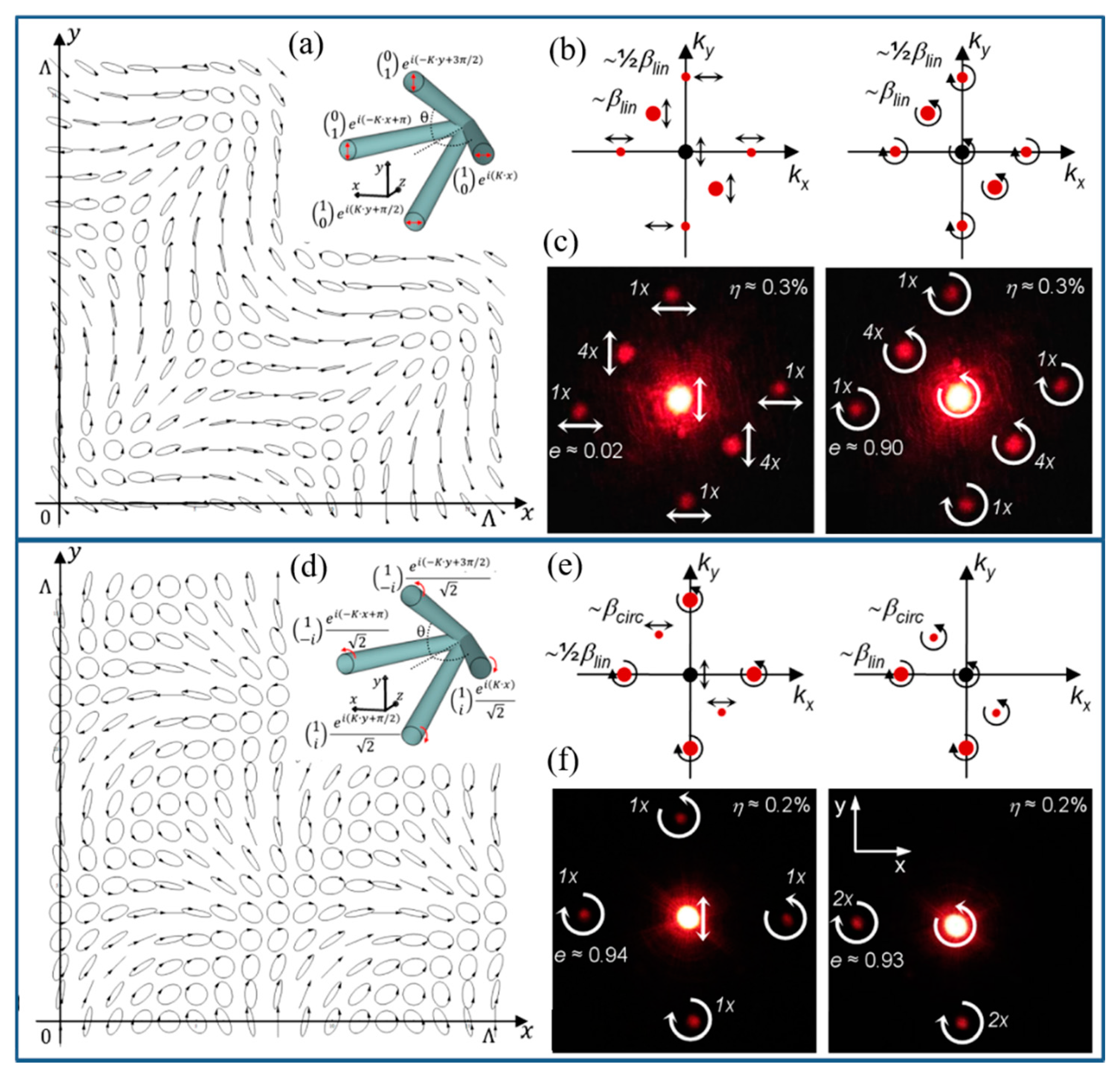
Figure 8.
(a) Arrangement and (b) polarization configurations of three interference beams: case i, case ii and case iii. (c) Simulated intensity and polarization states of the three cases. (d) Experimental diffraction patterns of the three cases. (e) Diffraction efficiency of spot A (open circles), B (filled circles) and C (open squares) as a function of azimuth polarization of the LP probing beam. Reproduced from Reference [45] with permission from AIP Publishing.

Figure 9.
(a) 2D polarization pattern of four interference beams with orthogonal linear polarization. Inset: Arrangement and polarization configurations of the interference beams. (b) Calculated and (c) experimental diffraction patterns for the 2D PG. (d) 2D polarization pattern and (e) calculated and (f) experimental diffraction patterns for the 2D PG based on four interference beams with circular polarization. Reproduced with permission from Reference [46] © The Optical Society.

Figure 10.
(a) Arrangement of the four interference beams. (b) Simulated intensity and (c) polarization states of the interference field. (d,e) Simulated LC texture and LC orientation between the crossed polarizers. (f) POM observation of the LC texture of the fabricated 2D PG. (g) The diffraction pattern varies with the input polarizations. (h) The diffraction efficiency as a function of relative phase retardation (Lines: Simulation result; Dots: Experiment result). (i) Polarization state of the diffraction pattern. (j) Polar plot of the polarization measurement of the 1st-order diffractions. Reproduced with permission from Reference [49] © The Optical Society.

Figure 11.
(a) Arrangement of three interference beams. (b) Simulated polarization pattern of the interference field. (c) LC texture observed by POM. (d) Arrangement of the interference by introducing a LP beam. (e) Simulated polarization pattern of the interference field when the LP light intensity is 1/5 of each CP light (valid throughout the figure). (f) LC texture of the fabricated 2D PG observed by POM. (g) Simulated diffraction pattern at the half-wave conditions. (h) Diffraction pattern of the 2D LC PG from the experiment. (i) Diffraction efficiency as a function of LC phase retardation. Lines: Simulation results; Scattered dots: Experiment results. (j) Polarization selectivity of the 2D LC PG diffraction based on the simulation. (k) Polar plot of the polarization measurements of the 1st-order diffractions. Reproduced with permission from Reference [53] © The Optical Society.

Figure 12.
(a) Schematic illustration of the LC sample with a micro-pixelated electric field. (b) The LC texture observed by POM with an illustration of the 2D LC director orientations. (c) The diffraction pattern of a CP incident beam with an applied 25-V 18.5 HZ ac voltage. The diffraction order is labeled based on the primitive cell vector of (d). (d) LC director orientation of unevenly tilted LC with umbilical defects. The normalized intensity of each diffraction spot observed in the experiment as a function of (e) the frequency with a fixed voltage and (f) the analyzer angle with a CP incident light. Simulated diffraction intensity as a function of the analyzer angle with a CP incident light, where the LC is assumed to have (g) planar alignment, as shown in (b), and (h) unevenly tilted alignment, as shown in (d). (a,c–g) Reproduced from Reference [57] with permission from the Royal Society of Chemistry. (b) Reproduced with permission from Reference [56] Copyright (2018) by the American Physical Society.

Publisher’s Note: MDPI stays neutral with regard to jurisdictional claims in published maps and institutional affiliations. |
© 2021 by the authors. Licensee MDPI, Basel, Switzerland. This article is an open access article distributed under the terms and conditions of the Creative Commons Attribution (CC BY) license (https://creativecommons.org/licenses/by/4.0/).
Share and Cite
MDPI and ACS Style
Zuo, K.; Shi, Y.; Luo, D. A Review of Two-Dimensional Liquid Crystal Polarization Gratings. Crystals 2021, 11, 1015. https://0-doi-org.brum.beds.ac.uk/10.3390/cryst11091015
AMA Style
Zuo K, Shi Y, Luo D. A Review of Two-Dimensional Liquid Crystal Polarization Gratings. Crystals. 2021; 11(9):1015. https://0-doi-org.brum.beds.ac.uk/10.3390/cryst11091015
Chicago/Turabian StyleZuo, Kai, Yue Shi, and Dan Luo. 2021. "A Review of Two-Dimensional Liquid Crystal Polarization Gratings" Crystals 11, no. 9: 1015. https://0-doi-org.brum.beds.ac.uk/10.3390/cryst11091015
Note that from the first issue of 2016, this journal uses article numbers instead of page numbers. See further details here.