Article

Investigation of Spectral Properties of DBR-Based Photonic Crystal Structure for Optical Filter Application

1
Department of Electronic Engineering, Balochistan University of Information Technology, Engineering and Management Sciences, Quetta 87300, Pakistan
2
Faculty of Engineering, Bahria University, Lahore Campus, 47-C, Civic Center, Johar Town, Lahore 54000, Pakistan
3
Faculty of Engineering and Computer Sciences, National University of Modern Languages, Islamabad 44000, Pakistan
4
School of Optics and Photonics, Beijing Institute of Technology, Beijing 100081, China
5
Department of Electronic Engineering, Quaid-e-Awam University of Engineering, Science and Technology, Nawabshah 67450, Pakistan
6
Institute of Microelectronics and Optoelectronics, Warsaw University of Technology, Koszykowa 75, 00-6625 Warszawa, Poland
7
Samara National Research University, 443086 Samara, Russia
*
Author to whom correspondence should be addressed.
Submission received: 15 February 2022 / Revised: 11 March 2022 / Accepted: 14 March 2022 / Published: 17 March 2022

Abstract

:
In this work, the spectral properties of distributed Bragg reflector-based photonic crystal (DBR-PhC) structures were studied for the near-infrared (NIR) range. Different structural properties were varied to study their effect on the quality of the stopband and the appearance of the resonant dips in the reflection spectra of the DBR-PhC structure. The investigated structural features included the depth of PhC holes, hole radius, and number of PhC elements in the DBR structure. The 11-layered DBR structure was designed with a 2.4/1.4 refractive index contrast of alternating layers. The study aimed to achieve optical filtering properties in the DBR-PhC structure, to simplify the structural complexity of Fabry-Pérot filters by eliminating the FP cavity and upper-DBR mirror. The proposed DBR-PhC device can be used in different optical filtering and sensing applications.

1. Introduction

In the past few decades, photonic devices have received much attention from researchers due to their significant advantages over their electronic counterparts in speed, power efficiency, and ease of use. Considering the optical filtering capabilities of photonic devices, photonic crystal (PhC) structures are one of the promising candidates that can confine and control the flow of photons at a wavelength scale. Initially, the concept of PhCs was presented in solid-state physics in the late 1980s [1,2]. PhC structures exist in one-dimension (1D), two-dimensions (2D), and three dimensions (3D), depending on the shape and the direction of energy confinement [3]. The 1D PhC structures are often known as distributed Bragg reflectors (DBRs), which is an established science already being used in various optical filtering [4] and sensing applications. Moreover, 2D PhCs are often applied as air hole-based gratings, drilled into slab waveguide structures. A category of PhC structures works on the principle of Fano resonances, which are also known as guided-mode resonances (GMR), where the incident light couples vertically with the surface of the structure [5,6,7,8]. Since DBRs also work on the principle of coupling energy vertical to the surface of the structure, these 1D PhCs (so-called DBRs) and 2D slab waveguide PhC structures can be integrated to combine their spectral characteristics. DBR mirrors, in general, offer a wide stopband and reflection of above 90%, and their use has already been demonstrated in a high-quality optical filter application in the form of Fabry-Pérot (FP) [4] filters. Meanwhile, sharp Fano resonances can be obtained by 2D slab waveguide PhC structures implemented into a single layer. By implementing a hybrid DBR-PhC structure where the PhC holes are drilled into DBR layers, the structural complexity and bulky size of an FP filter can be reduced. Moreover, the above-mentioned spectral features with a wide stopband and sharp Fano resonance can be combined to investigate the optical filtering properties of the hybrid DBR-PhC structure. A key structural parameter in hybrid DBR-PhC structures can be the structural features of the PhC holes, which can significantly affect the coupling of optical energy inside the periodic gratings and the quality of the guided modes inside the multilayered structure. Hence, optical tunability can be studied by varying the depth and radius of the PhC holes instead of the FP cavity thickness.
So far, single-layered and multi-layered PhC structures have been demonstrated in various applications such as optical filters [8,9,10], waveguides [11], logic gates [12], and biomedical sensors [13]. Similarly, the use of DBRs has been shown in applications like FP filters [4], sensors [13], spectroscopy [4,14], and numerous others. PhCs have been introduced to surface-emission lasers for the NIR wavelength range, along with the study of the role of the etching depth in PhCs [15,16]. A study on how to achieve spectral tunability by changing the depth of gratings in a micro-ring resonator was presented in [17]. Research combining DBRs with slab waveguide PhC structures to reduce the lateral losses of resonant modes in an optical filter design was put forward in [18]. Meanwhile, Ref. [19] offered an analysis of leaky modes in a three-layered asymmetric slab waveguide PhC structure, with variation in the refractive index contrast between the layers. An investigation into the appearance of guided modes from the interaction of a Bloch surface wave, as a function of grating geometrical parameters, in a structure with PhCs implemented in a single layer on top of DBRs, was carried out in [20]. In [21], the FP cavity of a DBR structure was distributed over several periods using the chirping effect, to widen the spatial distribution of the electric field of the resonant modes. The light emission of an oxide aperture was optimized by integrating PhC holes in the upper-DBR of a PhC-VCSEL (vertical cavity surface-emitting laser) in [22]. Similarly, the PhC hole-radius was investigated in the upper-DBR mirror of an InGaAlAs-based PhC-VCSEL for single-mode operation [23]. Similarly, a PhC defect-based laser cavity was demonstrated in 2D PhCs etched into DBR layers for the NIR range in [24]. Further to this, the enhancement of a second harmonic generation was optimized in an air-bridged dielectric structure with DBR layers and 2D PhCs in [25]. Research into the effects of 2D PhCs’ structural parameters on their spectral properties was reported in multiple works including [8,26]. However, a thorough study of the effect of the PhC hole depth on the spectral properties of hybrid DBR-PhC structures has not yet been presented.
In this work, a hybrid DBR-PhC structure was studied for optical filter application where the air hole-based PhC structures were patterned in the DBR layers. The considered DBR structure had a total of 5.5 periods (11 layers) with a refractive index contrast nH/nL = 2.4/1.4. Since the proposed device was designed to work in the NIR range, the DBR structures were designed for a central wavelength of λc = 1.5 µm, and the lattice constant of PhC holes was kept a = 1 μm. Since the simulation was performed in 2D-FDTD, the shape of the PhC holes appeared as 2D nano-grooves rather than 3D cylindrical air holes, and accordingly, the terms “hole depth” and “hole radius” should be considered as representing the depth and lateral size of the nano-grooves. A linear-polarized source was used to study the spectral properties of the proposed device. The hole depth (d), hole radius (r), and number of PhC-elements (N) were varied to study the spectral tuning and filtering properties of the proposed structure. The studied spectral characteristics were the width of stopband, percentage of reflection, free spectral range (FSR), fineness (F), and quality of the resonant modes appearing in the stopband.

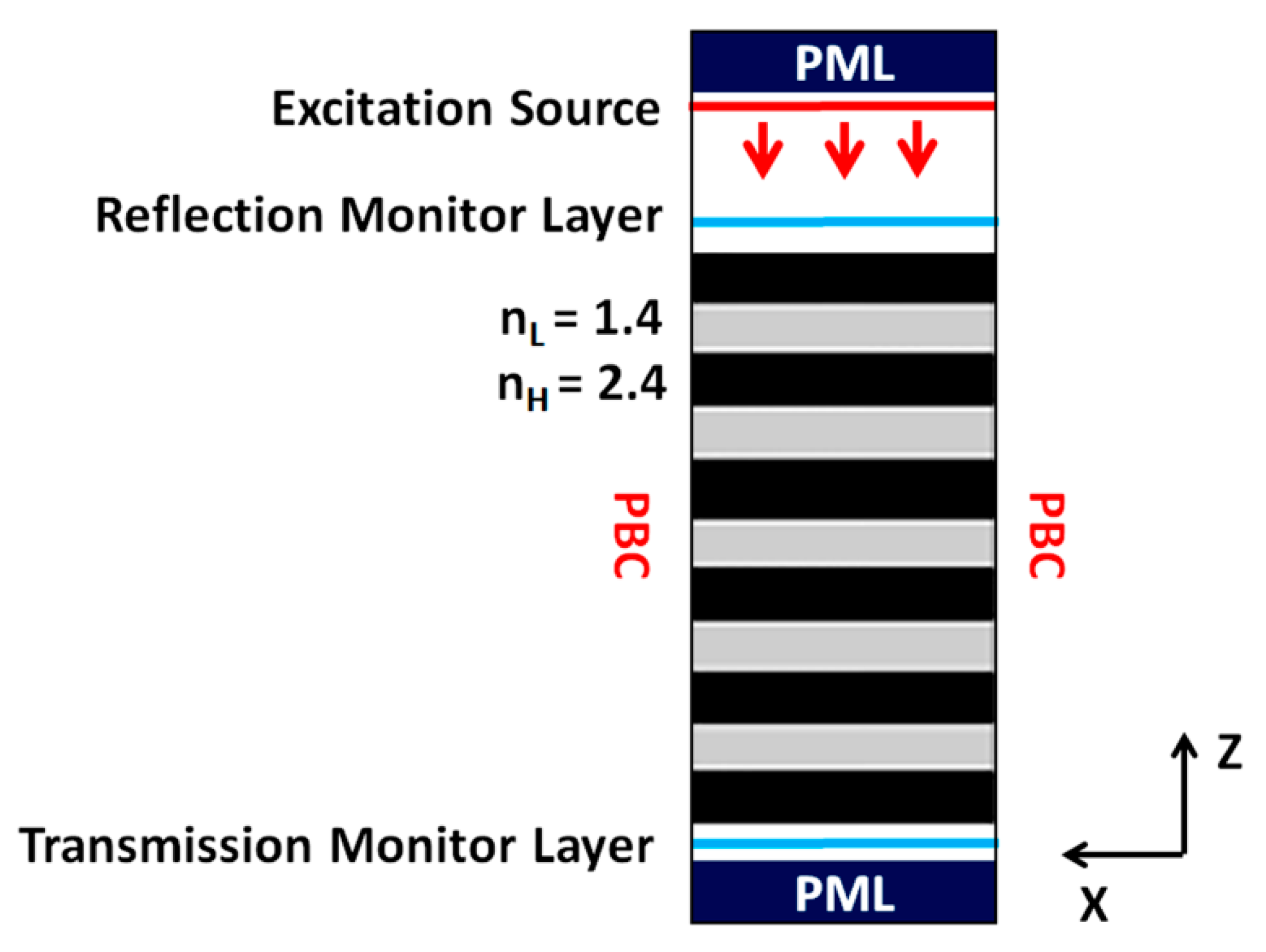
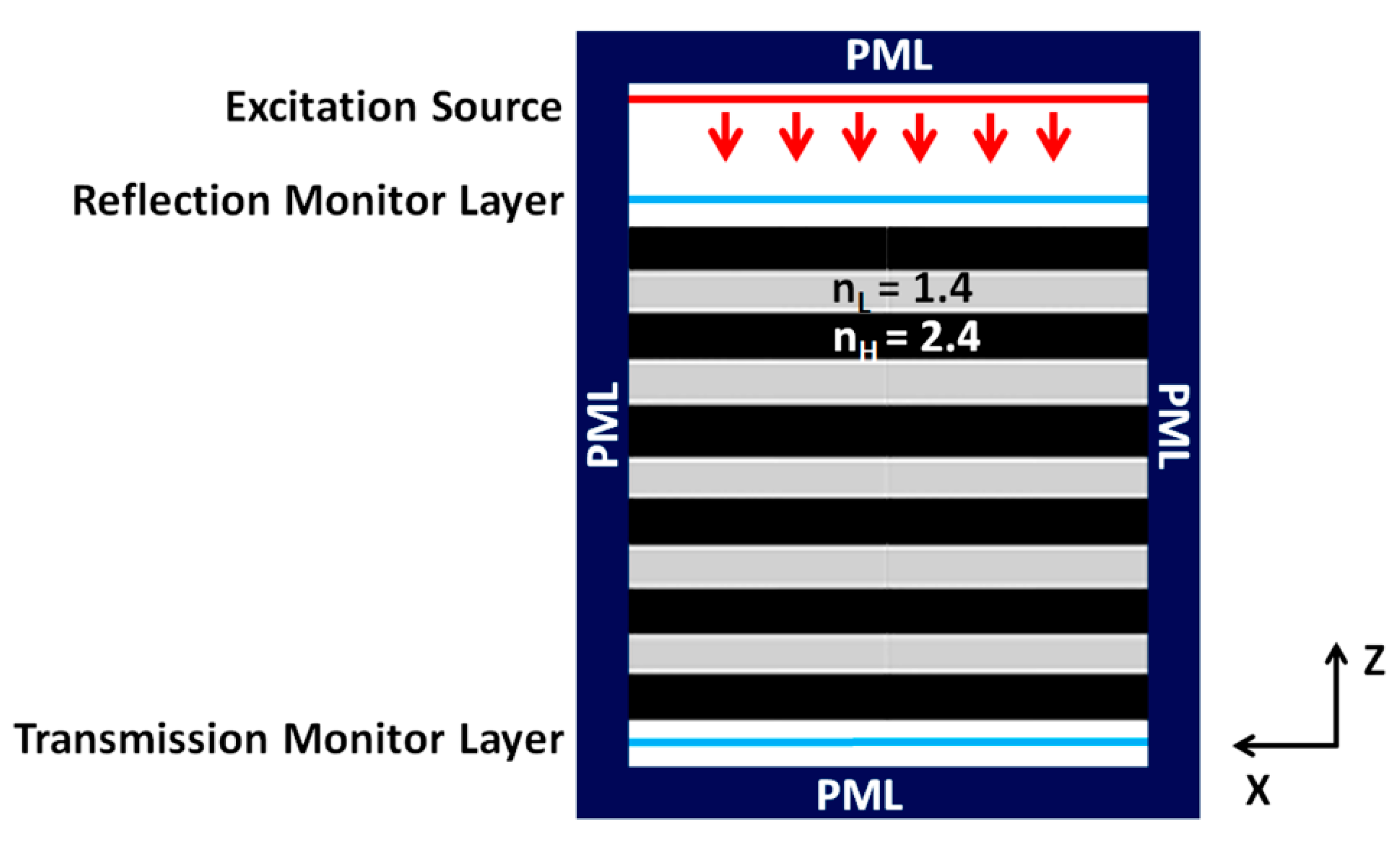
2. Materials and Methods

The design and numerical simulations of the proposed work were carried out in an open-source finite-difference time-domain (FDTD)-based software called MIT electromagnetic equation propagation (MEEP) [27,28]. The used FDTD method works on the principle of solving Maxwell’s equations in space and time to compute the electromagnetic field propagation. It also provides the advantage of being able to calculate the response of a system over a wide range of frequencies in a single run. To ease the complexity of the problem, the simulations were performed in the 2D-FDTD. A basic simulation model used in this work is depicted in Figure 1, showing the position of the excitation source, structure, and application of the boundary conditions. The simulation domain has an 11-layered DBR structure (L = 11) with an indication of the transmission and reflection field-monitoring layers below and above it, respectively. A plane wave source at a normal incidence was used for all the computations. Furthermore, a unit cell simulation approach was taken to optimize the basic structural parameters, i.e., d and r of the PhC holes. Moreover, Bloch’s periodic boundary conditions (PBC) were used in the lateral direction (x-axis) of the unit cell to simulate a perfect crystal and infinite structure. However, finite-dimensional problems such as the optimum number of PhC holes in x-direction were computed without the use of PBCs. To avoid back reflections and absorb the outgoing EM field, perfectly matched layer (PML) boundary conditions were used in the vertical direction (z-axis). To visualize the output spectra of the simulated problem, the resultant field from the time-domain simulation was converted to the frequency domain by applying Fourier transform. The constructive interference of reflection would occur in a DBR holding a quarter wavelength λ/4, equal to the product of physical thickness t and refractive indices nH/nL.
t = m λ c 4 n H   whereas ,   m = 1 , 2 , 3  
The above equation is the condition for in-phase interference where λc is the Bragg wavelength or central wavelength. The calculated optical thicknesses of the DBR layers (shown in Figure 1) are tH = 0.16 µm and tL = 0.27 µm for the layers corresponding to nH and nL, respectively.

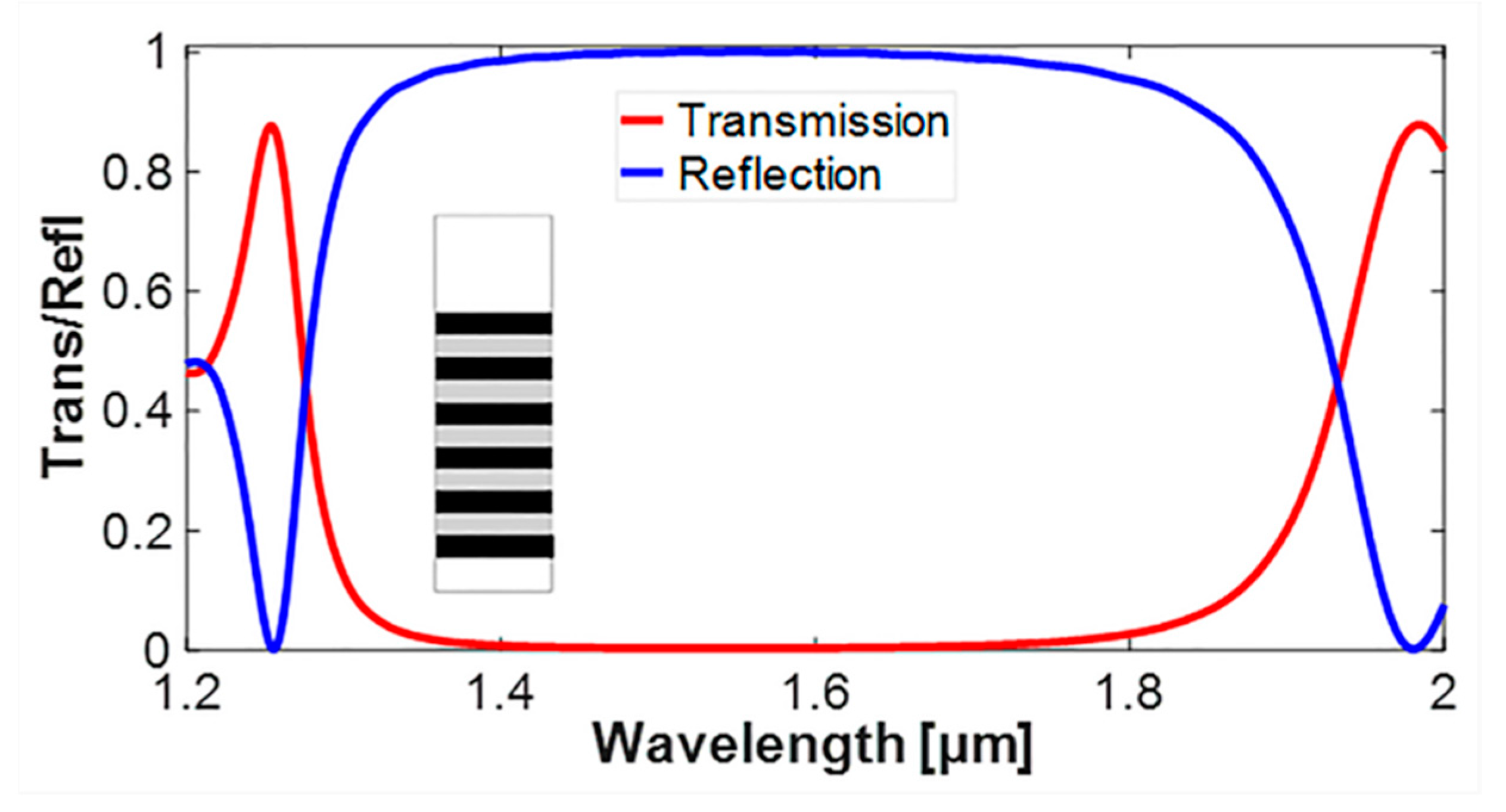
3. Results and Discussion

In the first step of the simulation, the transmission and reflection stopband of a DBR structure with 5.5 periods was computed as shown in Figure 2. The simulated DBR structure can be seen in the inset of Figure 2. The computed output spectra show a wide stopband starting from 1.274 µm and ending at 1.930 µm, with a width of around 0.656 μm. The stopband also portrays the property of DBRs with above 95% reflection over a wide range of wavelengths, which paves the way for further analysis, i.e., the introduction of PhC holes into the DBR structure.

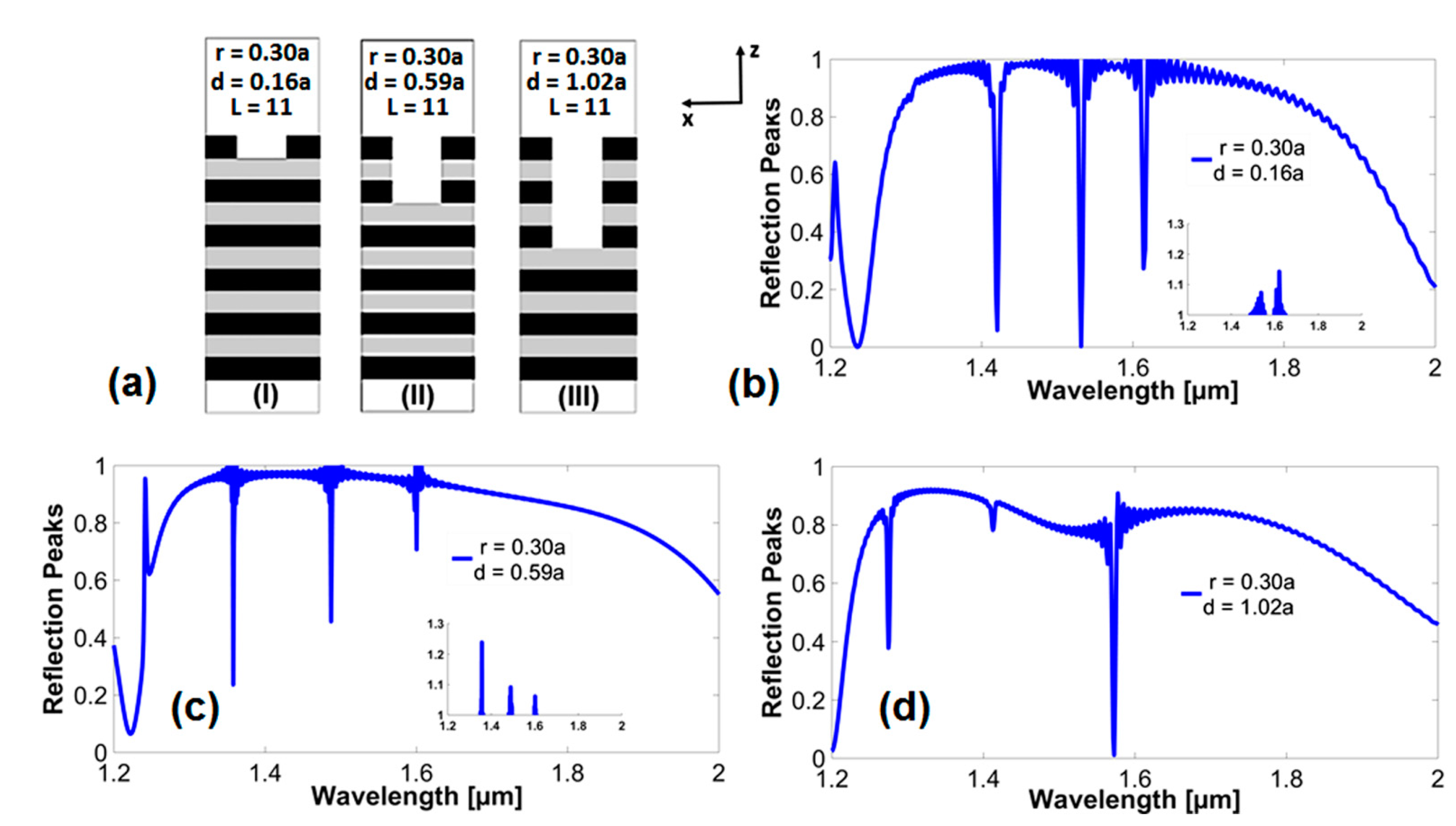
3.1. Effect of Depth of the PhC Holes

To study the effect of the presence of PhC holes in the considered DBR structure, a unit cell model was used. Figure 3a depicts the simulated structure with the introduction of a PhC hole into the DBR structure. The depth of the PhC hole is varied from the first layer to the fifth layer in steps, keeping all other structural parameters constant. The PhC hole has an optimized hole radius of r = 0.3a, where a represents the lattice constant of the PhC structure. The PhC structures can be scaled up or down to different spectral ranges just by changing the lattice constant, and therefore, their structural parameters are denoted in terms of lattice constant. Figure 3b shows the reflection spectrum of a DBR-PhC structure with a PhC hole present in the first layer. A single-mode and multi-mode dips are produced in reflection spectra as shown in Figure 3, representing the occurrence of Fano resonance in PhC structures [8]. The reflection spectrum shows three resonant modes, appearing around the 1.421, 1.532, and 1.615 µm wavelengths. The overall width of the stopband is 0.685 µm. Furthermore, increasing the depth up to the third DBR layer (1.5 periods) shows variation in the reflection spectrum depicted in Figure 3c. It can be observed that the spectral width of the stopband has increased up to 0.775 µm and the resonant modes appear around the 1.358, 1.487, and 1.60 μm wavelengths. Similarly, Figure 3d presents the reflection spectrum of the structure with d extended up to the fifth DBR layer. The reflection spectrum shows two sharp resonances located at wavelengths of 1.275 and 1.573 μm with the width of the stopband as 0.769 µm. Moreover, the change in the output spectra of the structures in terms of shifting the guided modes is due to variation in the effective refractive index and mode coupling efficiency as d increases.

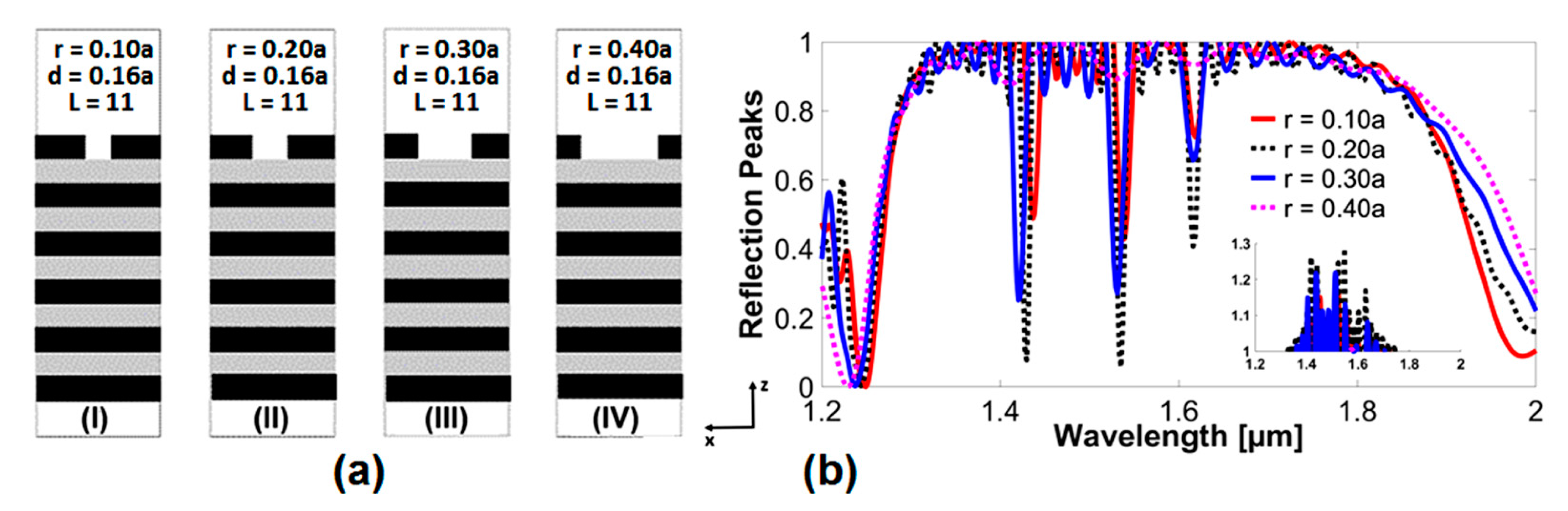
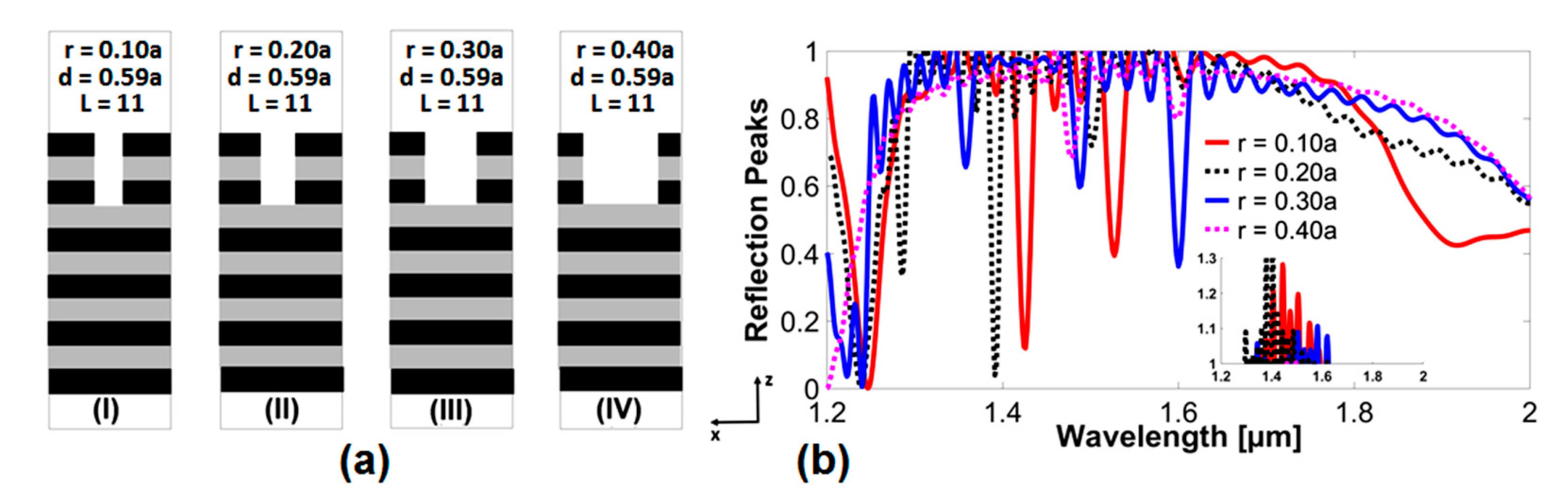
3.2. Investigating the Radius of PhC Holes with Holes Extending up to the First DBR Layer

To investigate the spectral characteristics of the DBR-PhC structure further, the hole radius is varied from r = 0.1a to 0.4a for three different case studies, i.e., d reaching up to the first, third, and fifth DBR layers. Figure 4a shows four structures with the hole depth reaching the first layer and simulated at values of r = 0.1a, 0.2a, 0.3a, and 0.4a. The reflection spectra of the discussed structures are shown in Figure 4b.
Referring to the reflection spectra in Figure 4b, strong evidence of energy-coupling and GMR can be seen. For the entire considered values of r, the appearance of three resonant modes can be seen around the wavelengths of 1.429, 1.535, and 1.616 μm. These resonant peaks are not very intense at r = 0.1a; they reach their maximum intensity at r = 0.2a, with two peaks reaching below the 10% reflection value. Furthermore, as r increases to r = 0.3a, the resonant mode dips start reducing and we observe a slight blueshift. At a larger value for the radius, i.e., r = 0.4a, the resonant modes almost disappear from the reflection spectrum.
The case study of variation in I is taken to three DBR layers in the third step, as shown in Figure 5a. Similar to the first case study, the guided modes show the strongest coupling and resonance at r = 0.2a, appearing around the wavelength of 1.395 µm. Furthermore, the amplitude of the resonant peaks also decreases with an increase in the hole radius. Among the designed radius values of the holes, r = 0.2a gives promising results, producing a single mode with good values for FWHM and finesse. Thus, for an optical-filtering application, a hole radius of r = 0.2a can be proposed.
Figure 6a shows variation in the r of PhC for d reaching up to the fifth DBR layer. Moreover, the reflection spectra in Figure 6b show strong coupling of resonant modes at r = 0.1a and 0.20a around the wavelengths of 1.36 and 1.40 µm. At larger values for the hole radius, i.e., r = 0.30a and 0.40a, the mode-coupling becomes weak and shows non-significant optical-filtering properties.

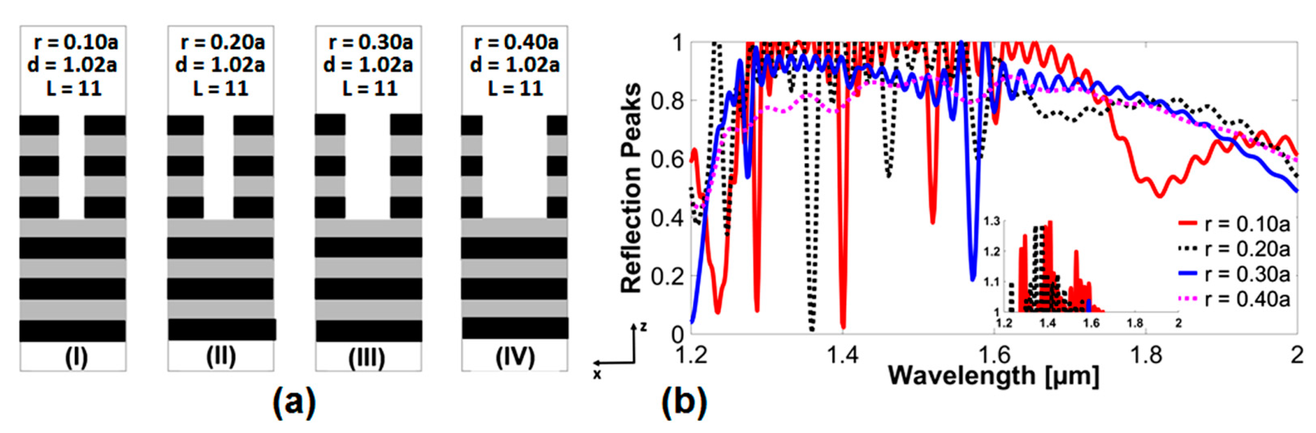
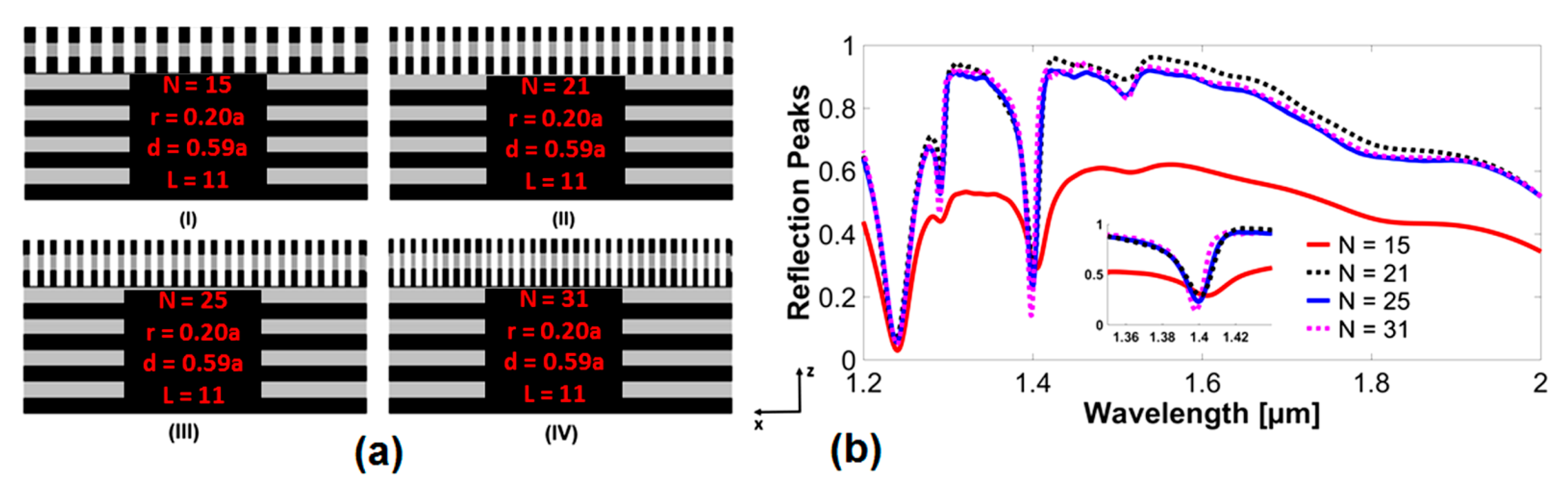
3.3. Investigating the Number of PhC Elements with Holes Extending up to the Third DBR-Layer

After optimizing the d and r values of the PhC holes in the unit cell model, it was crucial to investigate the total number of PhC elements N, to get the optimum optical filtering properties in a finite model. To investigate the number of PhC holes, we generated a finite DBR-PhC simulation domain, as shown in Figure 7, designed with PML boundaries applied in both the x and z-directions to absorb unwanted reflections and act as the boundaries of the structure.
Figure 8a depicts four different finite models of the DBR-PhC structure, with the number of PhC elements as N = 15, 21, 25, and 31. The d of the PhC holes is kept up to three DBR layers and an optimized value of r = 0.20a is used. When observing the reflection spectra of structures in Figure 8b, it can be seen that at N = 15, the overall reflection spectrum achieves a maximum value of 60% and the two resonant modes appear around wavelengths of 1.21 and 1.40 µm. As the lateral size of the structure increases and the numbers of PhC holes reach N = 21 and N = 25, the overall reflection spectrum rises above 90%, and as a result, the two main resonant modes become stronger. Meanwhile, for N = 31, the reflection spectrum drops abruptly to 58%, which shows the strengthening of leaky modes during GMR phenomena and weak optical-filtering properties. Consequently, as the percentage of the reflection for values of N = 21 and N = 25 is almost the same, the structure with N = 25 is selected due to the sharpness of its peaks, FWHM, and higher values of F. Since the lattice constant of the PhC structure is a = 1 µm in the presented work, it can be concluded that the total size of the DBR-PhC structure in x-dimension should be around 25 units for good optical-filtering characteristics.

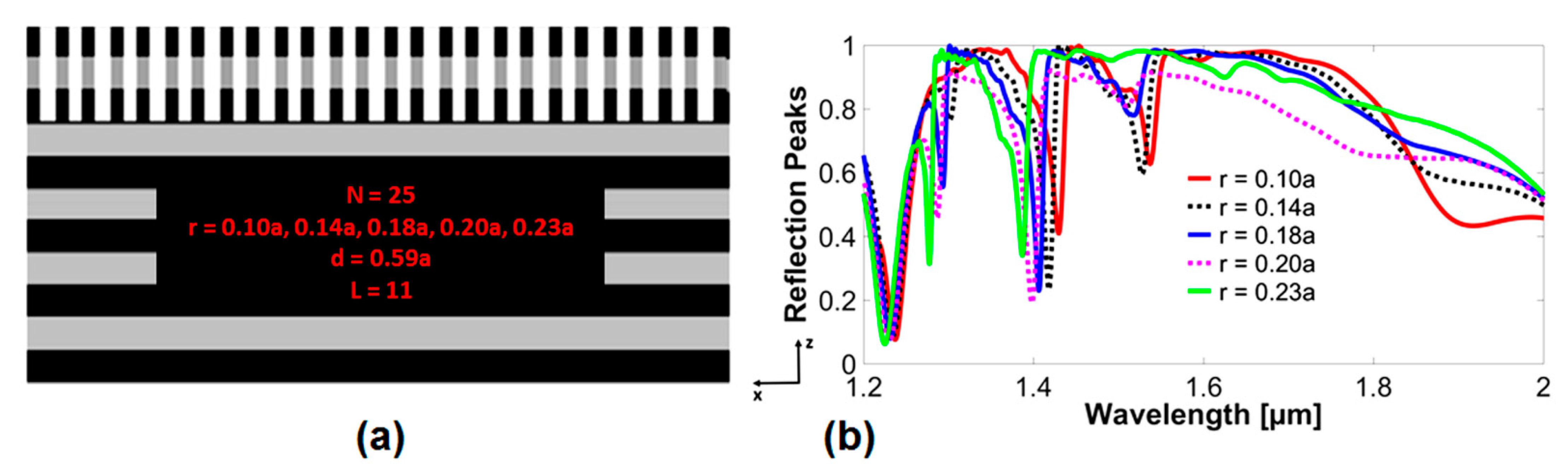
3.4. Spectral Tuning of Finite DBR-PhC Structure with N = 25 and Variation in Hole Radius

After reaching the optimum value of the number of PhC holes (N = 25) and with d equal to three DBR layers (Figure 9a), fine-tuning of the resonant peaks was required by varying the values of r. The reflection spectra for variation in the PhC hole radius, for r = 0.10a to 0.23a, are shown in Figure 9b. It can be observed that the resonant modes undergo a blueshift as the radius of the holes is increased. For r = 0.10a, the resonant modes appear at 1.423 and 1.432 μm, and similarly for r = 0.20a, at 1.4 and 1.409 μm, and for r = 0.23a, at 1.39 μm. The hole radius at r = 0.20a shows the lowest value of dip, reaching below 20%.
The optical characteristics of the simulated model in Figure 9a can be evaluated by considering the spectral parameters given in Table 1. The spectral parameters show that the reflection for r = 0.18a is 76%, followed by r = 0.14a with a 70% reflection, which gradually decreases for hole radius values of 0.2a, 0.23a, and 0.1a. Furthermore, r = 0.18a offers the least value of FWHM (0.016 µm) when compared to the rest of the hole radius values. Moreover, the largest value of FSR can also be observed with r = 0.18a. This demonstrates that for a good-quality factor or finesse, the hole radius 0.18a provides better results than the rest of the variable hole radius values. A comparative analysis of other spectral parameters concerning the effect of a change in the hole radius on the overall optical-filtering performance of the studied PhC-DBR structure can also be made by considering the parameters given in Table 1. The reported spectral characteristics of the DBR-PhC structure can be further validated by considering the thorough study of Fano resonances in multilayered dielectric PhC slabs reported in our previous work [8].

4. Conclusions

In this research, the optical-filtering properties of a hybrid DBR-PhC structure with 11 layers of DBR were studied in reflection spectra for the NIR spectral range. The proposed device possesses spectral characteristics with a wide stopband in reflection and with the presence of single as well as multiple resonant mode dips. The output spectra of the device show over 80% reflection for almost all the investigated structural properties, and the dip of the resonant modes reaches its best value of below 10% reflection. The investigated structural parameters included the depth of PhC holes, their radius, and the number of PhC holes. The depth and radius of the holes were investigated up to the fifth DBR layer. The optimum value for the PhC hole-depth was found to be one penetrating up to the third DBR layer, with the total number of PhC elements as N = 25 for a value of r = 0.18a. The optimized design offers a good value of finesse at 11.405, while the reflection of resonant peaks is below 20% and the FWHM is 0.016. The proposed device can be suggested as suitable for optical-filtering applications requiring a wide stopband and a compact device design. The device can be used as an alternative to an FP filter since it reduces the number of layers to less than half by eliminating the FP cavity and upper-DBR mirror. The device model will be further optimized in 3D-FDTD simulations in future work to bring it closer to becoming a real device model.

Author Contributions

Conceptualization, U.A. and Y.K.; methodology, M.K.E., M.R.A., N.U. and A.R.K.; software, U.A., Y.K. and A.U.R.; validation, Y.K., A.U.R., M.K.E. and M.R.A.; formal analysis, N.U., A.R.K. and M.A.B.; investigation, U.A., Y.K. and A.U.R.; resources, N.U., A.R.K., A.U.R. and M.A.B.; data curation, U.A., Y.K. and A.U.R.; writing—original draft preparation, U.A. and Y.K.; writing—review and editing, Y.K., A.U.R., M.K.E., M.R.A., N.U., A.R.K., A.U.R. and M.A.B.; visualization, U.A., Y.K., A.U.R., N.U. and M.R.A.; supervision, Y.K. and M.A.B.; project administration, Y.K., A.R.K. and M.A.B.; funding acquisition, Y.K. and M.A.B. All authors have read and agreed to the published version of the manuscript.

Funding

This research received no external funding.

Acknowledgments

The contribution of all the co-authors is greatly acknowledged and special thanks to Nanophotonics Research Group at BUITEMS Quetta for making this research possible.

Conflicts of Interest

The authors declare no conflict of interest.

References

  1. John, S. Strong localization of photons in certain disordered dielectric superlattices. Phys. Rev. Lett. 1987, 58, 2486–2489. [Google Scholar] [CrossRef] [PubMed] [Green Version]
  2. Magnusson, R.; Wang, S.S. New Principle for Optical Filters. Appl. Phys. Lett. 1992, 61, 1022–1024. [Google Scholar] [CrossRef]
  3. Koshiba, M.; Tsuji, Y.; Hikari, M. Time-domain beam propagation method and its application to photonic crystal circuits. J. Lightwave Technol. 2000, 18, 102–110. [Google Scholar] [CrossRef] [Green Version]
  4. Shen, Y.; Istock, A.; Zaman, A.; Woidt, C.; Hillmer, H. Fabrication and characterization of multi-stopband Fabry–Pérot filter array for nanospectrometers in the VIS range using SCIL nanoimprint technology. Appl. Nanosci. 2018, 8, 1415–1425. [Google Scholar] [CrossRef]
  5. Rybin, M.V.; Khanikaev, A.B.; Inoue, M.; Samusev, K.B.; Steel, M.J.; Yushin, G.; Limonov, M.F. Fano resonance between Mie and Bragg scattering in photonic crystals. Phys. Rev. Lett. 2009, 103, 23901. [Google Scholar] [CrossRef] [Green Version]
  6. Fan, S.; Joannopoulos, J.D. Analysis of Guided Resonances in Photonic Crystal Slabs. Phys. Rev. B 2002, 65, 235112. [Google Scholar] [CrossRef] [Green Version]
  7. Limonov, M.F.; Rybin, M.V.; Poddubny, A.N.; Kivshar, Y.S. Fano Resonances in Photonics. Nat. Photonics 2017, 11, 543–554. [Google Scholar] [CrossRef]
  8. Khan, Y.; Rehman, A.U.; Batool, B.A.; Noor, M.; Butt, M.A.; Kazanskiy, N.L.; Khonina, S.N. Fabrication and Investigation of Spectral Properties of a Dielectric Slab Waveguide Photonic Crystal Based Fano-Filter. Crystals 2022, 12, 226. [Google Scholar] [CrossRef]
  9. Shuai, Y.; Zhao, D.; Tian, Z.; Seo, J.H.; Plant, D.V.; Ma, Z.; Fan, S.; Zhou, W. Double-layer Fano resonance photonic crystal filters. Opt. Express 2013, 21, 24582–24589. [Google Scholar] [CrossRef] [Green Version]
  10. Butt, M.A.; Khonina, S.N.; Kazanskiy, N.L. Recent Advances in Photonic Crystal Optical Devices: A Review. Opt. Laser Technol. 2021, 142, 107265. [Google Scholar] [CrossRef]
  11. Vlasov, Y.A.; O’boyle, M.; Hamann, H.F.; McNab, S.J. Active control of slow light on a chip with photonic crystal waveguides. Nature 2005, 438, 65–69. [Google Scholar] [CrossRef] [PubMed]
  12. Fariborz, P.; Malmir, M.R. Reconfigurable All Optical Half Adder and Optical XOR and AND Logic Gates Based on 2D Photonic Crystals. Opt. Quantum Electron. 2020, 52, 1–8. [Google Scholar]
  13. Baker, J.E.; Sriram, R.; Miller, B.L. Two-dimensional photonic crystals for sensitive microscale chemical and biochemical sensing. Lab Chip 2015, 15, 971–990. [Google Scholar] [CrossRef] [PubMed] [Green Version]
  14. Horie, Y.; Arbabi, A.; Arbabi, E.; Kamali, S.M.; Faraon, A. Wide bandwidth and high resolution planar filter array based on DBR-metasurface-DBR structures. Opt. Express 2016, 24, 11677–11682. [Google Scholar] [CrossRef] [Green Version]
  15. Hsu, M.; Lin, G.; Pan, C.-H. Electrically injected 1.3-μm quantum-dot photonic-crystal surface-emitting lasers. Opt. Express 2017, 25, 32697–32704. [Google Scholar] [CrossRef]
  16. Li, Z.L.; Lin, S.C.; Lin, G.; Cheng, H.W.; Sun, K.W.; Lee, C.P. Effect of etching depth on threshold characteristics of GaSb-based middle infrared photonic-crystal surface-emitting lasers. Micromachines 2019, 10, 188. [Google Scholar] [CrossRef] [Green Version]
  17. Amiri, I.S.; Zakaria, R.; Yupapin, P. Manipulating of nanometer spacing dual-wavelength by controlling the apodized grating depth in microring resonators. Results Phys. 2019, 12, 32–37. [Google Scholar] [CrossRef]
  18. Kusserow, T.; Khan, Y.; Zamora, R.; Messow, F.; Hillmer, H. Guided-mode resonances in dielectric photonic crystal slabs with low index contrast. In Proceedings of the 2012 International Conference on Optical MEMS and Nanophotonics, Banff, AB, Canada, 6–9 August 2012; IEEE: Piscataway, NJ, USA, 2012; pp. 170–171. [Google Scholar]
  19. Zhang, H.; Zhu, H.; Qian, L.; Fan, D. Analysis of leaky modes of photonic crystal slabs with deeply patterned lattice. J. Opt. A Pure Appl. Opt. 2006, 8, 483–488. [Google Scholar] [CrossRef] [Green Version]
  20. Baghbadorani, H.K.; Aurelio, D.; Barvestani, J.; Liscidini, M. Guided modes in photonic crystal slabs supporting Bloch surface waves. J. Opt. Soc. Am. B 2018, 35, 805–810. [Google Scholar] [CrossRef]
  21. Taimoor, M.; Reuter, S.; Hillmer, H.; Kusserow, T. Narrowband optical thin-film filters with distributed cavity modes. Appl. Phys. A 2016, 122, 1–5. [Google Scholar] [CrossRef]
  22. Xie, Y.Y.; Xu, C.; Kan, Q.; Wang, C.X.; Chen, H.D. Lowering the threshold current of photonic crystal vertical-cavity surface-emitting lasers. Iraqi J. Appl. Phys. 2013, 21. [Google Scholar] [CrossRef]
  23. Czyszanowski, T.; Dems, M.; Thienpont, H.; Panajotov, K. Optimal radii of photonic crystal holes within DBR mirrors in long wavelength VCSEL. Opt. Express 2007, 15, 1301–1306. [Google Scholar] [CrossRef] [PubMed]
  24. Painter, O.; Lee, R.K.; Scherer, A.; Yariv, A.; O’brien, J.D.; Dapkus, P.D.; Kim, I. Two-dimensional photonic band-gap defect mode laser. Science 1999, 284, 1819–1821. [Google Scholar] [CrossRef] [PubMed] [Green Version]
  25. Luo, M.; Liu, Q.H. Extraordinary enhancement of second harmonic generation in a periodically patterned distributed Bragg reflector. J. Opt. Soc. Am. B 2015, 32, 1193–1201. [Google Scholar] [CrossRef]
  26. Burr, G.W.; Diziain, S.; Bernal, M.P. The impact of finite-depth cylindrical and conical holes in lithium niobate photonic crystals. Opt. Express 2008, 16, 6302–6316. [Google Scholar] [CrossRef] [PubMed]
  27. Lambert, E.; Fiers, M.; Nizamov, S.; Tassaert, M.; Johnson, S.G.; Bienstman, P.; Bogaerts, W. Python Bindings for the Open-Source Electromagnetic Simulator Meep. Comput. Sci. Eng. 2010, 13, 53–65. [Google Scholar] [CrossRef] [Green Version]
  28. Oskooi, A.F.; Roundy, D.; Ibanescu, M.; Bermel, P.; Joannopoulos, J.D.; Johnson, S.G. Meep: A Flexible Free-Software Package for Electromagnetic Simulations by the FDTD Method. Comput. Phys. Commun. 2010, 181, 687–702. [Google Scholar] [CrossRef]
Figure 1. Simulation model depicting an excitation source, DBR structure, reflection, and transmission monitoring layers with the application of boundary conditions.
Crystals 12 00409 g001
Figure 2. Output spectrum of the DBR structure where red (transmission) and blue (reflection) lines represent a stopband of 0.656 μm with λc = 1.5 µm.
Crystals 12 00409 g002
Figure 3. The reflection spectra of DBR structure with variation in the depth of the PhC holes. (a) DBR-PhC structure with PhC hole in (I) first layer, (II) third layer, and (III) fifth layer. (b) Depth of PhC holes reaching the first DBR layer. (c) Depth of PhC holes reaching the third DBR layer. (d) Depth of PhC holes reaching the fifth DBR layer.
Crystals 12 00409 g003
Figure 4. (a) 2D unit cell model of PhC structure with d extending up to the first layer and r varying as (I) 0.1a, (II) 0.2a, (III) 0.3a, and (IV) 0.4a. (b) Reflection spectra of the structure for r = 0.1a, 0.2a, 0.3a, and 0.4a.
Crystals 12 00409 g004
Figure 5. (a) 2D unit model with hole depth limited to third DBR layer and r varying as (I) 0.1a, (II) 0.2a, (III) 0.3a, and (IV) 0.4a. (b) Reflection spectra of the structure for r = 0.1a, 0.2a, 0.3a, and 0.4a.
Crystals 12 00409 g005
Figure 6. (a) DBR structure with PhC holes reaching up to fifth layer and radius varying between (I) 0.1a, (II) 0.2a, (III) 0.3a, and (IV) 0.4a. (b) Reflection spectra of DBR-PhC structures for variation in value of hole radius in five DBR layers.
Crystals 12 00409 g006
Figure 7. A finite 2D-FDTD simulation model of the hybrid DBR-PhC structure, representing the positions of the excitation source, reflection and transmission monitoring layers, and PML boundaries.
Crystals 12 00409 g007
Figure 8. (a) Finite 2D-FDTD simulation models of DBR-PhC structures with variation in number of PhC elements as follows: (I) N = 15, (II) N = 21, (III) N = 25, and (IV) N = 31, and with r = 0.2a and d extending to three DBR layers. (b) Reflection spectra of the DBR-PhC structure with variation in the number of PhC elements.
Crystals 12 00409 g008
Figure 9. (a) Finite 2D-FDTD simulation models DBR-PhC structures with N = 25 and variation in value of hole radius. (b) Reflection spectra of the DBR-PhC structure with variation in the hole radius.
Crystals 12 00409 g009
Table 1. Spectral parameters of DRB-PhCs structure used to evaluate its spectral characteristics.
Radius (a)Resonant Peak Reflection (%) FWHM (μm)FSR (μm)Finesse
0.1053%0.0220.4334.863
0.1470%0.0210.98248.757
0.1876%0.0163.0781211.405
0.2065%0.0180.861727.232
0.2359%0.0190.44115.882
Publisher’s Note: MDPI stays neutral with regard to jurisdictional claims in published maps and institutional affiliations.

