
Effect of Forced Melt Flow on Al–Si Eutectic-Alloy Microstructures

1
Institute of Physical Metallurgy, Metal Forming & Nanotechnology, University of Miskolc 1, 3515 Miskolc, Hungary
2
MTA-ME, Materials Science Research Group, University of Miskolc 2, 3515 Miskolc, Hungary
*
Author to whom correspondence should be addressed.
Crystals 2022, 12(5), 731; https://0-doi-org.brum.beds.ac.uk/10.3390/cryst12050731
Submission received: 27 April 2022
/
Revised: 12 May 2022
/
Accepted: 17 May 2022
/
Published: 19 May 2022
(This article belongs to the Special Issue Microstructure Characterization and Design of Alloys)
Abstract
:Al–Si eutectic alloys are industrially important; they play a significant role in the casting-manufacturing of most materials. The properties of the materials are governed by their microstructure, which can be tuned by adjusting the solidification process parameters. Herein, the effect of forced melt flow on the microstructure of an Al–Si eutectic alloy during unidirectional solidification was investigated experimentally. Al–12.6-wt%-Si alloy samples were solidified in a vertical Bridgman-type furnace equipped with a rotating magnetic inductor to induce flow in the melt. The samples were subjected to different magnetic induction conditions during the solidification experiments. The diameter of the samples was 8 mm, and their length was 120 mm. The eutectic alloy samples were solidified unidirectionally at a growth rate of v ≈ 0.1 mm/s and a temperature gradient of G ≈ 6 K/mm. The inter-lamellar distances (λ), lengths, and orientation angles of the Si lamellae were investigated using new measurement methods. The experimental results reveal that applying the rotating magnetic field (RMF) during the solidification has a distinct effect on the microstructure of Al–Si eutectic alloys. Indeed, the RMF refines the eutectic structure, reduces the interlamellar distances, and increases the diversity of the Si lamella angle’s orientations. However, the successive stirring process has a negligible effect on the lengths and angles of Si lamellae.
1. Introduction
Aluminium–silicon alloys are among the most widely used materials in casting industries because of their combination of good castability and essential mechanical properties, that is, good corrosion resistance and wear resistance. Owing to these properties, Al–Si alloys are implemented in various automotive and aerospace applications—motor blocks, cylinder heads, pistons, etc. The Al–Si alloys used therein are eutectic; the two phases of Al and Si grow simultaneously from a liquid state at a constant temperature [1,2]. The eutectic reaction occurs at 12.6 wt% Si and at an equilibrium temperature of 577 °C. A modification process can change the morphology of Si particles, which are plate-like.
In 1966, Jackson and Hunt developed the most comprehensive model that explains eutectic-structure formation. They simplified the issue of diffusion ahead of the solidification front by assuming planar interface solidification and identical undercooling of the melt in front of the solid phases that grow together from the eutectic melt [3]. Many other explanations are based on the Jackson–Hunt model, which developed new approaches to explain the relationship between various parameters—growth rate (v), undercooling of the melt (ΔT), temperature gradient (G), and microstructural factors such as inter-lamellar distance λ and lamellar length [4,5,6,7,8].
The structure of an Al–Si eutectic alloy is irregular eutectic. Microstructural measurements are challenging due to the formation of lamellae (plural of lamella) with undefined orientations and varying lengths. For example, when characterising the size of the eutectic structure, researchers usually compare two microstructural photos of different samples and describe the microstructures as ‘fine or finer’ and ‘coarse or coarser’ [9]. These descriptions, devoid of any numerical indication, cannot sufficiently characterise the size of the eutectic structure.
Several methods have been used to measure inter-lamellar distances. One such method is direct measurement, in which the examiner acquires a transverse or longitudinal microstructural photograph and manually measures the inter-lamellar distances [10]. Clapham [11] adopted the line intercept method to measure inter-lamellar distances. The measurement is performed by drawing a line in the ‘Wheatsheaf’ formation of the eutectic lamellae, whose axes are perpendicular to the quenched interface. Each line is nearly orthogonal to several lamellae. The inter-lamellar distance is calculated by dividing the line length by the number of lamellae crossed by the line (Figure 1). However, eutectic Al–Si alloys consist of many Si eutectic lamellae with different growth directions; therefore, the inter-lamellar-distance measurement becomes very complicated. In both methods (direct measurement and line intercept), a limited number of measurements is performed on select parts of the eutectic-structure sample. Therefore, the results of these methods are highly dependent on the examiner and human factors. Some researchers adopt an alternative, ‘fibre spacing method’, for the measurement [12]. This method aims to measure the distance between the primary dendritic arms on primary phases in the dendritic structures by considering the number of particles (N) and area (A) to calculate the spacing (λ). [λ = √(A⁄N)]. However, the fibre spacing method does not take account of two important factors, namely, the specific area of each component (phase ratio) and the eutectic size factor.
Melt flow is an important parameter that affects microstructure development during solidification. Melt flow can be categorised as natural or forced convection. Natural convection occurs as a consequence of many factors: contraction (or expansion) when the densities of solid and liquid phases are different and gravitational force during the solidification. On the other hand, forced convection occurs when external conditions are applied. A rotating magnetic field (RMF) can be used to control the melt flow. The RMF changes the heat and mass transfer conditions in the melt ahead of the solid–liquid interface, which leads to significant changes in the microstructural evolution of the resulting alloy [13].
Previous studies have proven that forced melt flow causes structural refinement and macro-segregation in the melted alloy. However, the detailed mechanisms of the RMF effect during melt solidification remain unclear. Fragoso and Santos provided different explanations for the mechanism of size refinement due to a magnetic field [14]. Yasuda and Nakatsuka stated that due to electromagnetic vibration, the primary arms of dendrites are cut off in the initial stage of solidification. These fragments are spread out and act as nuclei [15,16]. Some studies attributed the size refinement to the fact that electromagnetic undercooling increases the number of atomic clusters that collide with intermetallic particles ahead of the solidification front, which leads to an increase in the number of nuclei. In addition, the forced convection carries the separated nuclei from the walls of the mould to the centre of the sample [17,18]. Other studies demonstrated the existence of undercooling effects due to the magnetic intensity.
Quenisset and Naslain developed a theoretical model to anticipate the change in lamellar spacing caused by the use of forced convection during the solidification of regular eutectic. They concluded that the lamellar spacing increases with the intensity of stirring and that the well-known correlation between lamellar spacing and solidification rate R, λ2R = constant, should be adjusted when the strength of convection gets sufficiently significant [19]. However, the opposite result was obtained when a magnetic field was applied to an Al–Si irregular eutectic structure, where the lamellar distances decreased with increasing magnetic intensity [20,21]. The change of lamellar spacing under the magnetic field was attributed to the ability of the forced convection to affect the diffusion process in front of the solid–liquid interface. A preliminary investigation was performed regarding this aspect, and it was found that the diffusion coefficient D was reduced due to the effect of the magnetic field [22]. Our work aims to investigate the effect of forced melt flow on the microstructure of Al–Si eutectic alloys. The inter-lamellar distances (λ), length, and angle between the Si lamellae and the direction of heat extraction (sample axis) were analysed using new measurement methods. Al–12.6-wt%-Si alloy samples were solidified unidirectionally in a crystalliser equipped with a High Rotating Magnetic Field (CHRMF) device. The details of the experiment are presented in the following section.
2. Materials and Methods
2.1. Materials and Experiments
Al–12.6-wt%-Si eutectic alloy samples composed of Al (99.95 wt% pure) and Si (99.95 wt% pure) were used for the solidification experiments. Unidirectional solidification experiments were performed using the vertical upward Bridgman method. The dimension of the cylindrical samples (to be solidified) was Ø 7.1 mm × 110 mm. The solidification process was performed in a CHRMF device [23]. The crystalliser consisted of a furnace with a programmable temperature controller, a water-cooling unit, a repeater or step motor to control the movement of the sample, 13 thermocouples of different lengths around the sample, and a MagnetoHydroDynamic stirring (MHD) inductor, which generated a rotating magnetic field during solidification. Unidirectional solidification was realised by the vertical translation of the sample relative to the furnace chamber.
For the experimentation, the eutectic alloy samples were solidified unidirectionally in five steps; the magnetic intensity in each step was different (Table 1). The following solidification parameters were applied: average solid–liquid interface velocity v ≈ 0.1 mm/s, average temperature gradient G ≈ 6 K/mm, and with/without magnetic stirring (B). The growth rate (v) and temperature gradient (G) were calculated from the measured cooling curves.
- Step 1: Unidirectional solidification without magnetic stirring for up to 55 mm length.
- Step 2: Unidirectional solidification using 150 mT magnetic induction at the end of the sample.
2.2. Complex Characterisation of the Irregular Eutectic Structure
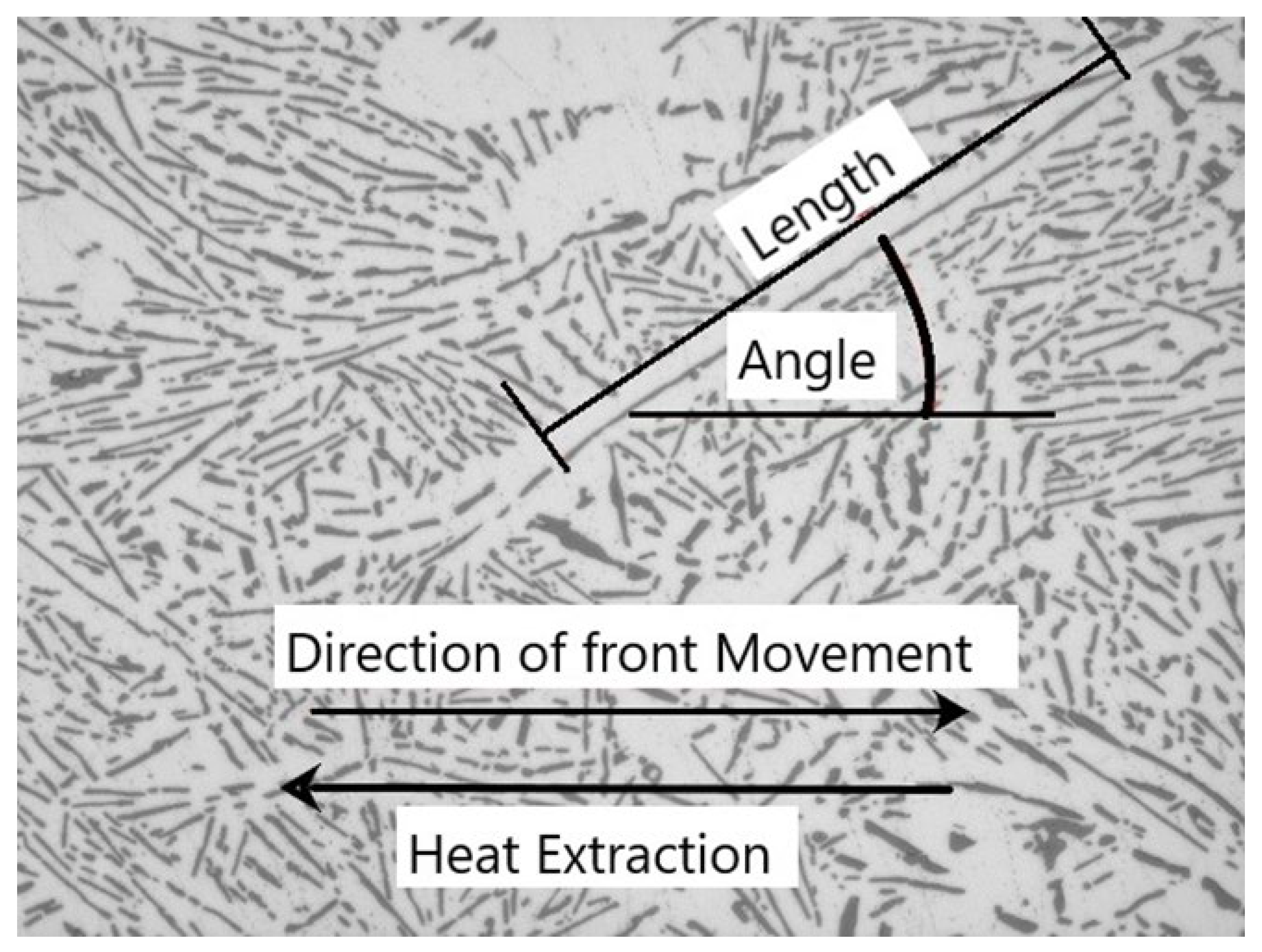
Characterising the irregular eutectic structure has been challenging for researchers because each eutectic lamella has a different length, thickness, inter-lamellar distance, and angle. Here, angle represents the inclination between the axis of the lamellae and the direction of solidification movement (heat extraction). We considered the following parameters to describe the irregular eutectic structure: average inter-lamellar distance (λ), length, and angle of the Si lamella.
This study adopted the ‘Specific Perimeter Method (SPM)’ to measure the inter-lamellar distance (λ). SPM was developed by our research group to address the shortcomings of other methods and has been validated [24]. The inter-lamellar distance (λ) is given by Equation (1).
where,
- P0: average perimeter of the Si lamella in the investigated light-microscopy images (μm); it can be measured using image analysis software.
- N: number of eutectic lamellae.
- Ap: area of the micrograph (μm2).
- Af: area fraction of eutectic lamellae in the eutectic structure.
The length of the lamellae was measured to be equal to the Ferret diameter, which is the distance between two parallel tangential lines that force the object to be perpendicular to that direction. New image processing techniques facilitate the measurement and analysis of the Ferret diameter of each object, that is, for every eutectic Si lamella. The measured Ferret diameters were divided into ranges, and the percentage distribution of lamellae within a given range was investigated. In addition, angle measurements were performed; they describe the orientation between the axis of the eutectic Si lamella and the solidification direction (Figure 2).
3. Results and Discussion
3.1. Mesostructure and Macro-Segregation
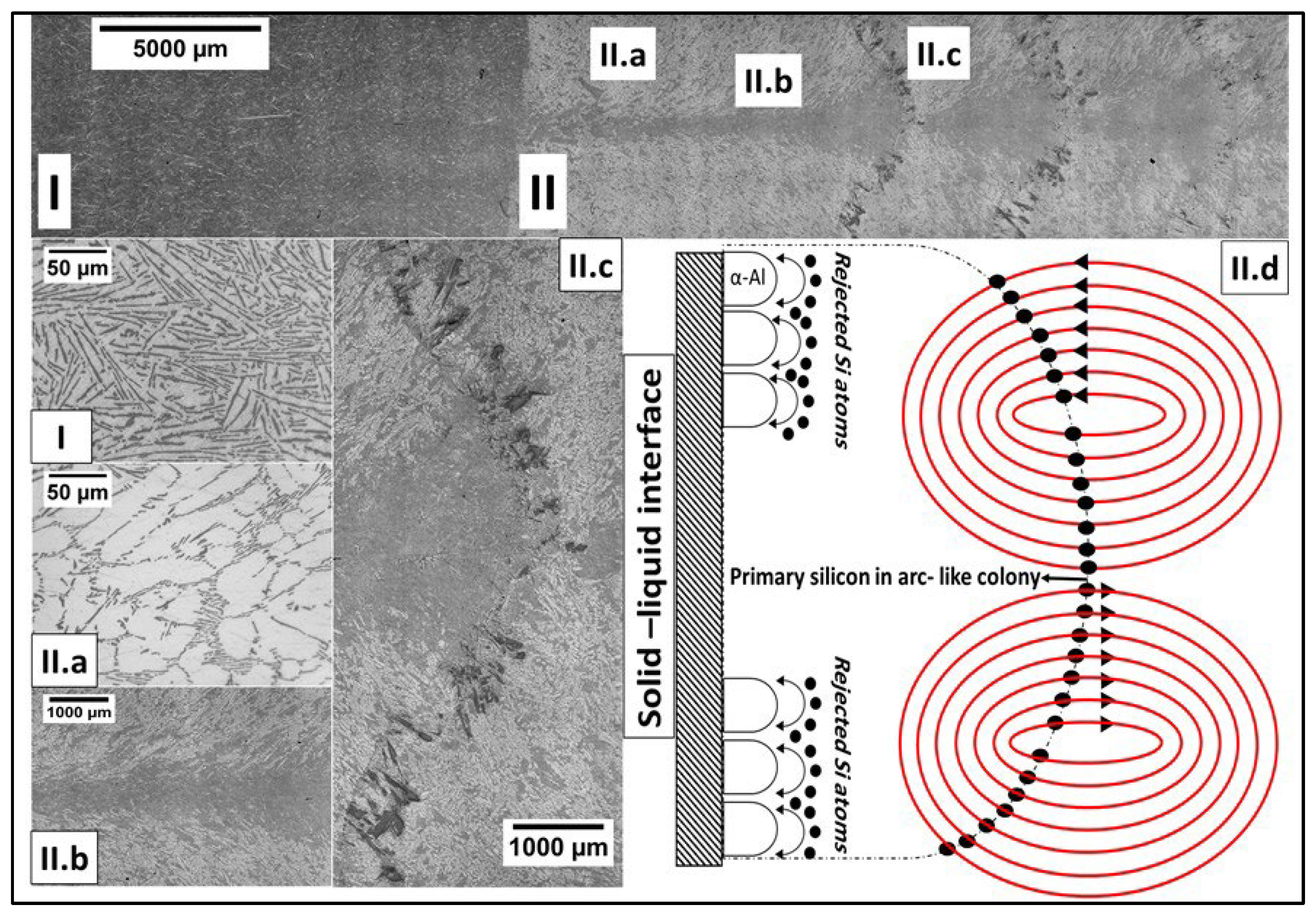
The solidified samples were sectioned longitudinally and prepared by grinding, polishing, and etching in a 2 vol% aqueous HF solution. Figure 3 shows the micrographs of the longitudinal sections of AlSi100. The structure of the sample solidified without stirring (Figure 3I) is homogeneous, that is, free from macro-segregation. The non-stirred parts have an irregular eutectic structure. Solidification under the influence of stirring (Figure 3II) resulted in a significantly different macrostructure.
The fluid flow underlying the rotating magnetic stirring is crucial for comprehending the effect of magnetic stirring during solidification. An RMF promotes two types of flow in the molten liquid. (i) Primary (azimuthal) flow, which results from the interaction of free electrical charges in the liquid with the magnetic field. This interaction generates the Lorentz force, which is the main driver of the primary flow and causes the liquid to rotate around the centre axis of the sample. However, the Lorentz force is not uniform along the sample; it reaches the maximum at the horizontal mid-plane of the cylindrical sample and decreases at the top and bottom. (ii) Secondary (meridional) flow, caused by the imbalance between the centrifugal force and radial pressure gradient near the horizontal walls. This flow has the form of two toroidal vortices in the r–z plane, which transport the alloying element from the mushy zone ahead of the growing interface to the pure liquid. As a result of the combination of these two flows, the heat and mass transport in the melt is complicated, and the motion is spiral motion, which significantly affects the growth morphology.
RMF is an efficient tool for changing the fluid flow and, consequently, the solute distribution. However, the homogeneity in the solute concentration is not signified herein. Wang et al., in their reviews [25,26], state that a low magnetic stirring intensity may suppress the formation of macro-segregation. However, when a steady magnetic intensity is applied, characteristic macro-segregation patterns appear because of the underlying flow structures.
The following mechanism is proposed for explaining the macrostructural evolution when the molten eutectic liquid is immersed in 100 mT magnetic induction.
- Owing to the spiral flow, the solute is transferred from the edges to the centre-axis channel. Consequently, the primary Al solidifies at the edges (Figure 3II.a), whereas the eutectic structure solidifies at the centre area.
- In the case of low magnetic induction, laminar flow occurs, in which a fluid flows in parallel layers without any disruption between the layers. However, when a high magnetic intensity is applied, the laminar flow loses its stability and converts to turbulent flow. The turbulent flow is characterised by the random appearance of Taylor and Gortler (T–G) vortices along the sidewall of the cylindrical sample. The T–G vortices transport the rejected solute in both directions between the mushy zone and molten liquid. Willer reported a significant amplification in the radial flow when the T–G vortex impinges the mushy zone, signifying that, in the radial flow, the solute transport is enhanced momentarily along the mushy zone [27]. Local re-melting occurs at the spots where a high Si concentration exists near the axis. As a result, the interface changes to a wavy shape, and the eutectic structure solidifies in the form of a side-arm freckle around the axis of the sample. This segregation pattern is referred to as Christmas-tree-like (CTL) segregation (see Figure 3II.b).
- When super-high magnetic induction is applied, the velocity of the flows transporting the solute is very high. Thus, a large amount of solute is transferred. The CTL segregation pattern reduces the amount and concentration of the solute by solidifying as a eutectic structure in the side-arm freckle around the axis; however, the amount of solute remains high. This is described by another segregation pattern, which manifests as periodic arc-like colonies along the sample (Figure 3II.c). Two scenarios are proposed to explain arc-like colony solidification. (i) The Taylor and Gortler vortices transport the solute from the liquid to the mushy zone. Owing to the high magnetic intensity, the impingements of the T–G vortices on the mushy zone cause a large radial flow. This flow has the form of complete radial waves towards the liquid and transports a high concentration of Si. Local re-melting occurs in spots with high Si concentrations, causing solidification of the primary Si phase in arc-like colonies ahead of the solid–liquid interface. (ii) The secondary flow results in the formation of arc-like primary Si colonies. The secondary meridional flow transports the rejected Si atoms from the mushy zone to the liquid and from the liquid to the mushy zone during recurring inversion. This leads to the accumulation of the transported Si in the flow paths. The flow paths near the axis experience a momentary reduction in the Si concentration owing to the solidification of the eutectic side-arm freckles. This indicates that the axis area requires much time to attain the Si concentration required to form primary Si. The case is different for the flow paths near the edges because no concentration reduction occurs therein; therefore, the primary Si forms earlier in the edges than at the axis. The time required to attain the primary-Si concentration varies with the flow path. The flow paths near the sample axis require more time, whereas those near the edges of the sample require less time. As a result, the primary Si gradually solidifies into an arc-like colony (Figure 3II.d).
- After the first Si arc-colony solidification, the overall concentration returns to the original value, that is, the eutectic concentration. However, magnetic stirring continues; therefore, the previous mechanism periodically repeats until the RMF is switched off.
3.2. Eutectic Lamellae’s Distances (λ)
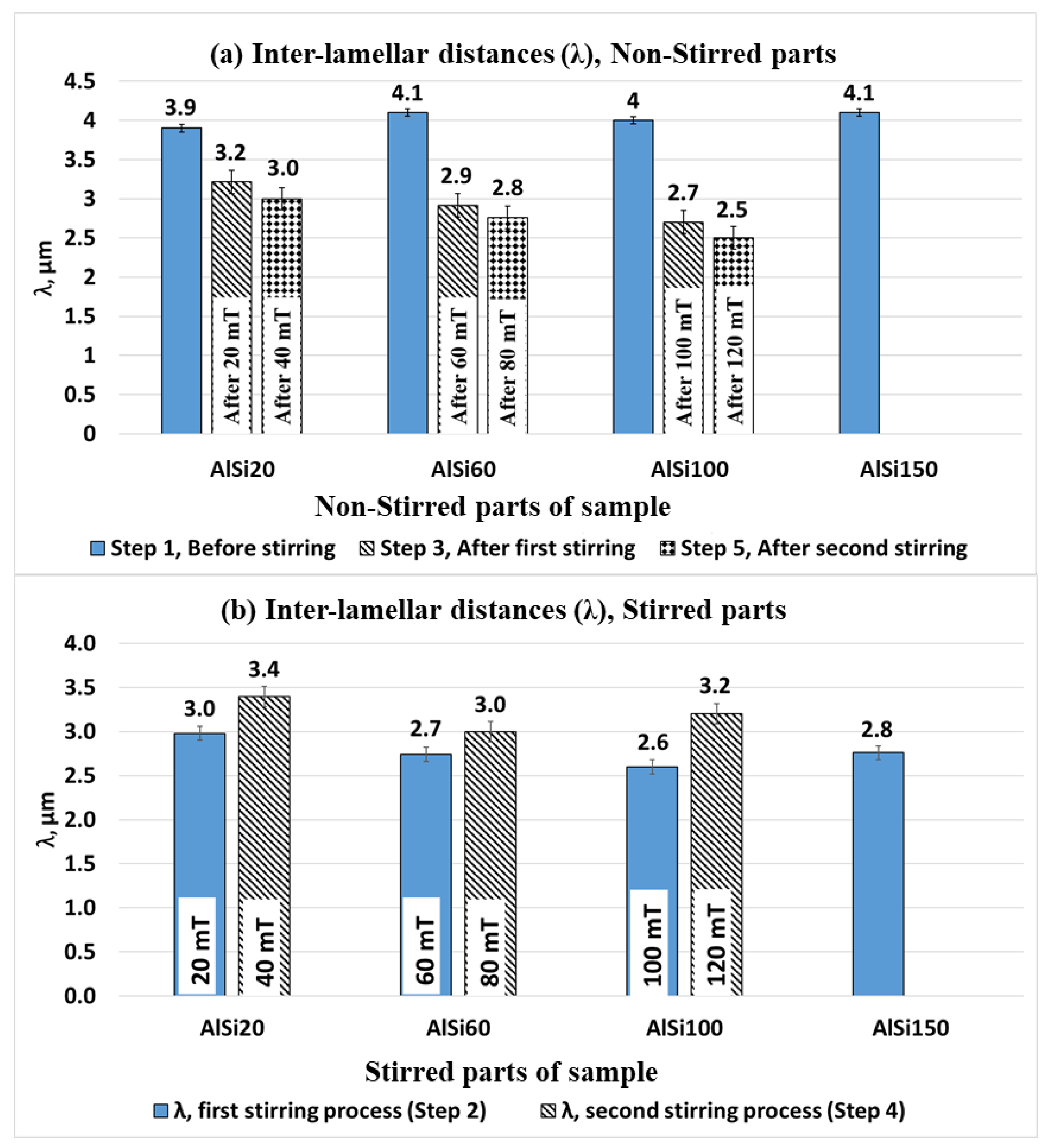
Inter-lamellar distances were measured using the specific perimeter method. In general, the stirring process reduces the inter-lamellar distances in the non-stirred parts. Figure 4a shows the measurement results of the non-stirred parts of the samples in Step 1 (before stirring), Step 3 (after the first stirring), and Step 5 (after the second stirring) of solidification. The following conclusions are drawn: (i) If the molten liquid is stirred many times in a row, the inter-lamellar distance decreases after each stirring process. (ii) The intensity of magnetic induction has a pronounced effect on the inter-lamellar distances after stirring; in the AlSi20 sample, the inter-lamellar distances after 20 and 40 mT were 3.2 and 3.0 µm, respectively. The same trend was observed when a higher magnetic field intensity was applied.
In the stirred parts, the measurements were performed in the centre-axis area, that is, where the eutectic structure solidifies. Figure 4b shows that successive stirring processes increase the inter-lamellar distances in the stirred parts.
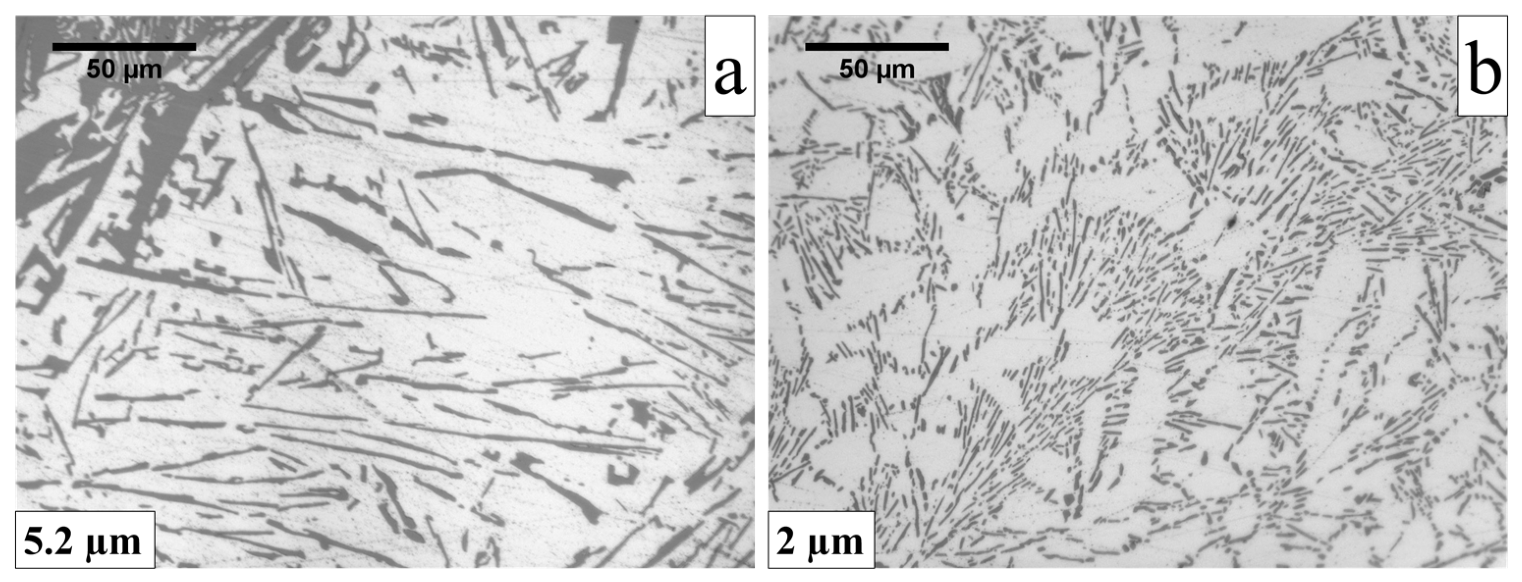
Owing to the macro-segregation phenomenon in the stirred parts, the primary Si and the primary Al solidify. The eutectic structure near these phases has different characteristics compared to the eutectic structure that solidifies at the centre of the sample. The eutectic structure, which co-exists with the primary Si phase, is a degenerated eutectic, that is, a coarse eutectic structure (λ ≈ 5.2 μm in Figure 5a). However, it is finer when it is near the primary Al phase (λ = 2 μm in Figure 5b). Further, an increase in the stirring intensity only affects the amount of the primary Si and Al solid solution phases; it does not significantly affect the inter-lamellar distance of the surrounding eutectic.
3.3. Eutectic Lamellar Lengths
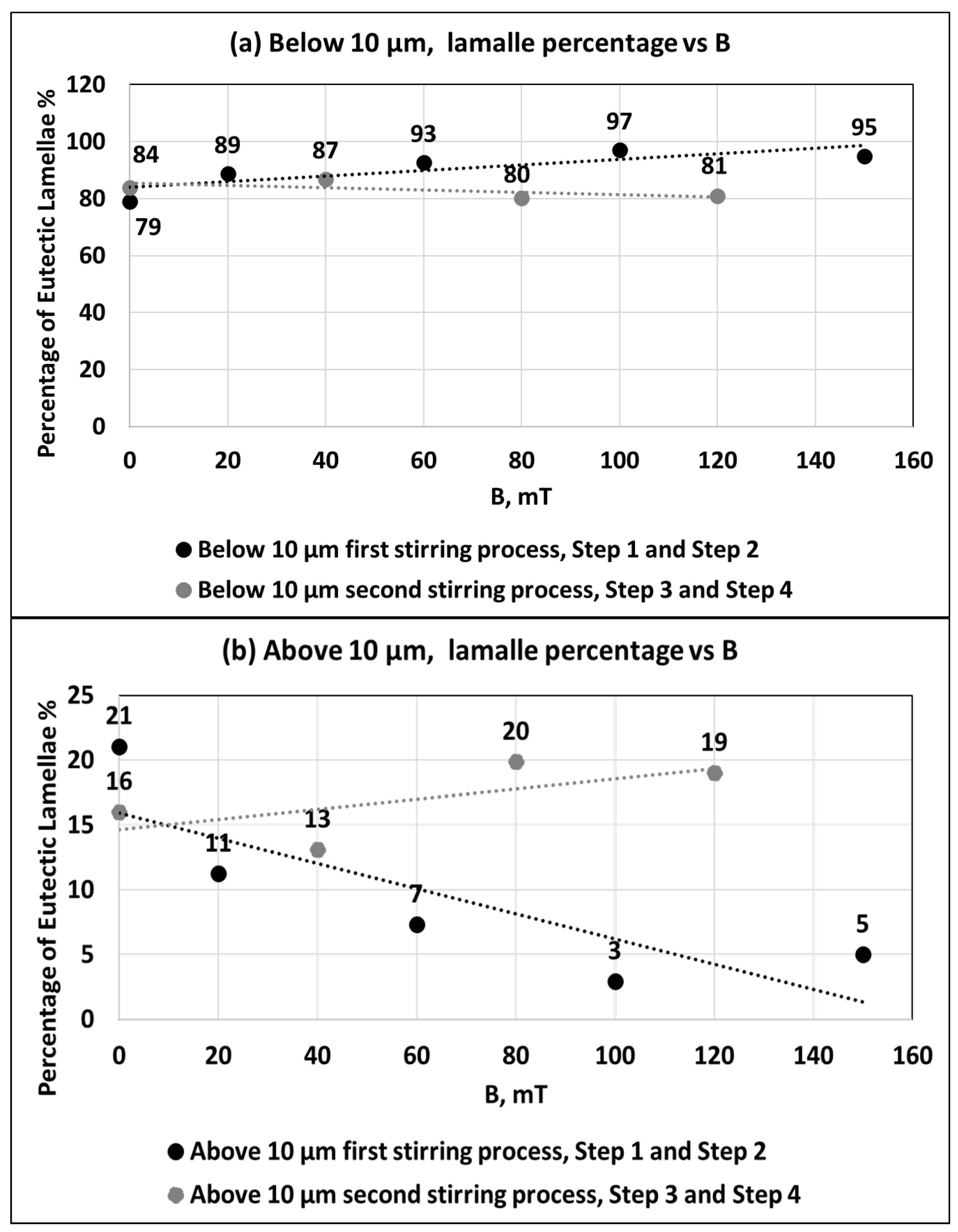
Length measurements were performed by measuring the Ferret diameter of the projection on each Si eutectic plate. The measurements were analysed by categorising the eutectic Si plates into two ranges: fine eutectic structures <10 μm and coarse eutectic structures >10 μm. This procedure was followed for all stirred and non-stirred parts. For concision, we used the average measurements of the non-stirred parts in Step 1 (before stirring) and Step 3 (after the first stirring).
Figure 6 shows the distinct effect of the RMF on Si lamellar size refinement. The fine Si range (<10 μm) had the highest percentage of stirred and non-stirred parts. However, the percentages of fine Si plates were higher in the case of RMF, especially during the first stirring process (Figure 6a). On average, 78% of the Si lamellae had a length less than 10 μm in the non-stirred parts at step 1. This percentage increased with stirring intensity. When applying a 20 mT magnetic intensity, the percentage of the smallest lamellae increased to 89%. Applying 60 mT magnetic induction increased the rate to 93%. The increment was also observed when 100 and 150 mT magnetic induction were applied to stir the molten liquid, in which the measured percentages were 97% and 95%, respectively.
However, the mechanism of size refinement is not yet well understood. The consensus is that the solidification rate increases owing to the mass transportation of the cooled liquid from the mould perimeter to the hotter regions. Mass transport leads to solute undercooling [17]. The fine structure solidifies when solute undercooling occurs. In Step 3 of solidification (before the second stirring), the samples were solidified without instant RMF stirring. However, because the samples were stirred previously, the resulting microstructure reflected the earlier RMF in Step 2. This possibly explains the higher average percentage of the fine eutectic Si plate in Step 3 (84%) than in Step 1 (78%) of the solidification experiment. In addition, when the sample was stirred for the second time in Step 4, the microstructure showed an unexpected behaviour. The percentage of fine eutectic Si lamellae was less than that in the first stirring process (Step 2). For example, with the second stirring (80 mT) in Step 4 of the solidification of sample AlSi60, the percentage of fine eutectic Si lamella decreased to 80% from 93% in the first stirring part (60 mT). The comparison of the percentages of Step 4 (120 mT) and Step 2 (100 mT) of the AlSi100 yielded the same observation, in which the percentages were 80% and 97%, respectively. This inference applies to the AlSi20 as well. Further studies are needed to determine the reason behind this behaviour for the second stirred parts.
The decrease rate of the coarse eutectic Si lamellae matched the increase rate of the fine eutectic structure (Figure 6b). The second stirring process did not significantly affect the lengths of the Si lamellae, regardless of whether the eutectic structures were fine (<10 μm) or coarse (>10 μm).
3.4. Eutectic Lamellar Angles
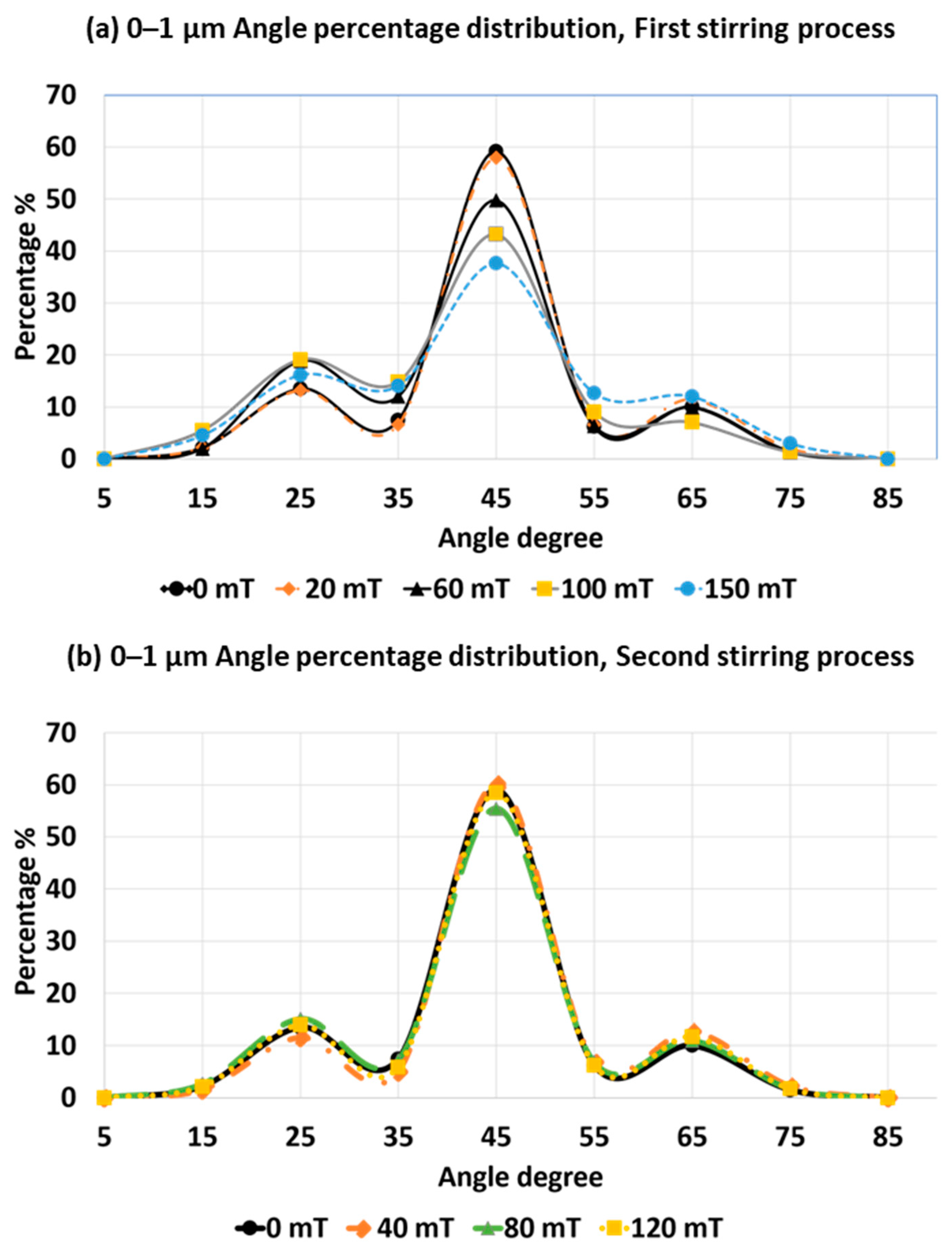
The lamellar angle describes the degree of inclination between the axis of projection of the eutectic Si lamellae and the direction of solidification movement. The eutectic lamellar angles were analysed by the following steps. (i) The sizes of eutectic Si lamellae were categorised into four different ranges: 0–1, 1–5, 5–50, and >50 µm. (ii) The angle of each Si lamella was measured in each size category using ImageJ processing software. (iii) The percentage of Si lamellae with the same angle was then calculated. (iv) An angle percentage distribution curve was plotted for each size category for different parts of the samples.
Figure 7 shows the angle distribution curve for the 0–1 µm size category for different parts. In the curve, each point represents a range. For example, the 45° angle represents the angle range (40°–50°) on the angle axis. Figure 7a demonstrates a distinct effect of RMF on the angle distribution during the first stirring process, that is, Steps 1 and 2 of the solidification experiments. When the solidification process takes place without the effect of the force melt flow, 60% of the fine eutectic lamella (0–1 μm) tends to orient 45° from the sample axis. The remaining lamellae in this size category orient in different directions. There are two local minimum percentages around 45°, in which the percentage of the Si lamellae at 55° is 5% and that at 35° is 7%.
Stirring the molten liquid by RMF reduces the maximum percentage at 45° and increases the diversity of the angle orientation. When RMF is switched on and 20 mT is applied during solidification, a slight decrease in the percentage is observed (58%), but in the case of 60 mT, a significant percentage decrease (50%) occurs. Increasing the magnetic intensity to 100 and 150 mT led to percentage decreases of 43% and 38%, respectively. This decrease in percentage in the 40–50° range corresponds to increments in the other angle ranges, especially the two local minimum percentages, 35° and 55°.
Figure 7b shows the angle distribution curve for the size range 0–1 µm during Steps 3 and 4 of the solidification experiments. In Step 3, the samples were solidified without instant stirring, but the molten liquid was stirred previously during Step 2. The angle distribution curve of Step 3 is identical to that of Step 1 (series 0 mT in Figure 7a), signifying that the angle percentages remained unchanged before and after the stirring process. This inference is valid even during the second stirring process in Step 4. The angle distribution curves for the parts, which were stirred twice, show a similarity in values (series 40, 80, and 120 mT).
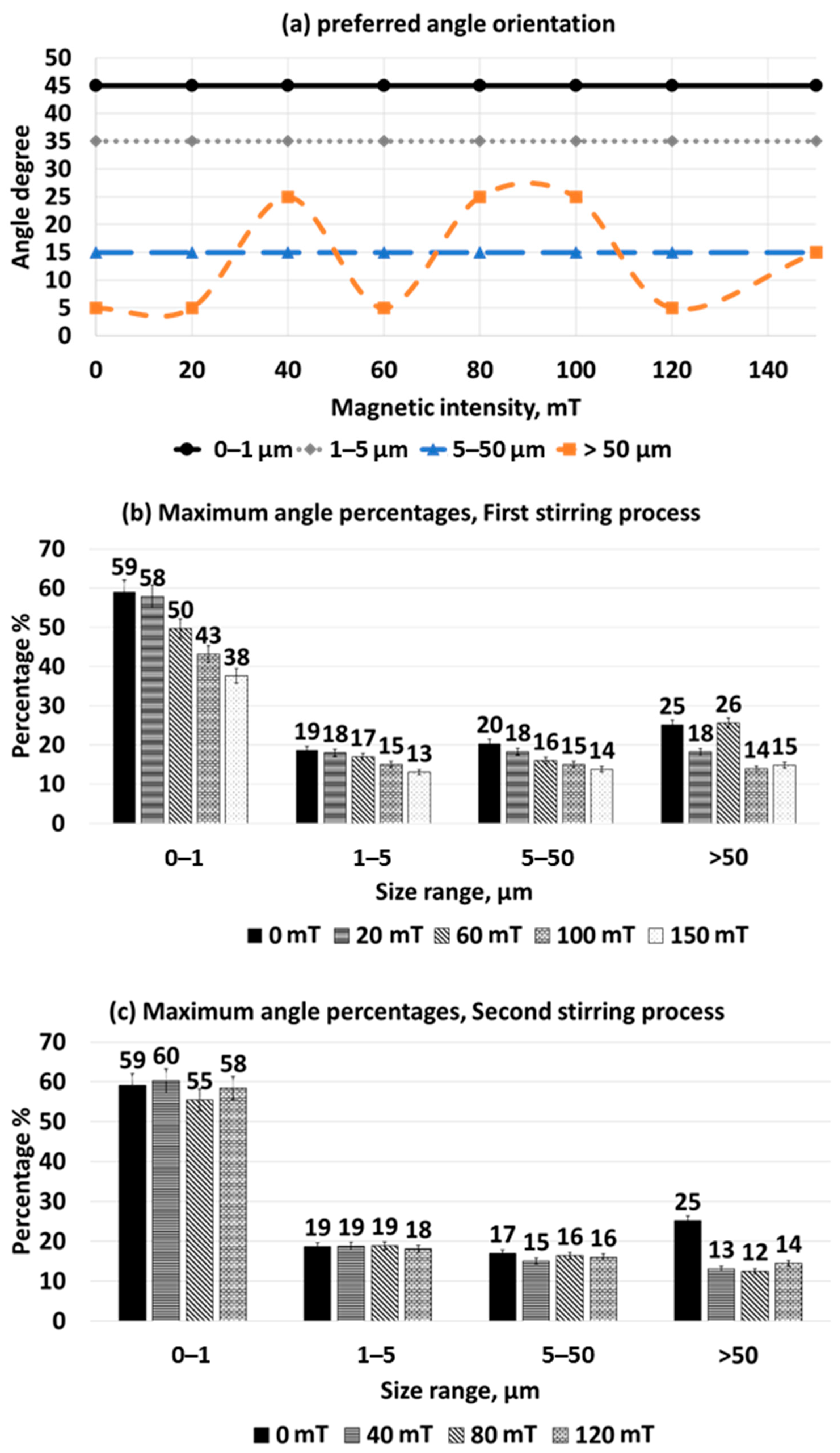
As mentioned previously, the preferred angle orientation for fine eutectic lamellae (0–1 µm) is 45°. Using the same measurement method, we characterised the preferred angles of other size categories, as shown in Figure 8a. As shown in the figure, the lamellae located in the 1–5 µm size category prefer to orient at 35°, while those located in the 5–50 µm size category tend to orient at 15°. For lamellae that are bigger than 50 µm, the preferred angle fluctuates because there are very few Si lamellae in that size range. Thus, those lamellae cannot be representative of the >50 µm category. These results infer that the larger the Si lamellae, the more likely they are to orient parallel to the solidification movement because the preferred angle decreases when the lamellar size increases.
Thus far, the preferred angle for each size range has been determined. However, the maximum percentage of Si lamellae which solidify in the preferred angle orientation varies with the sample parts. Figure 8b shows the change in the maximum percentages for each size category during the first stirring process, that is, Steps 1 and 2. The maximum percentages decreased with increasing stirring intensity. The decrease in the maximum percentages at the preferred angle is matched by corresponding increases in the percentages of other angles. This leads to the conclusion that increasing the stirring intensity leads to a high diversity of the Si lamellar angles, and the conclusion holds true for all size ranges. However, the lamellae >50 µm exhibited an unusual change pattern, which is also attributed to the lack of a sufficient number of Si lamellae that represent this size category.
After the first stirring process, the samples were solidified without an instant effect of the RMF, in Step 3 of the solidification experiments. The results demonstrate a perfect correlation between the angle distributions after (series 0 mT in Figure 8c) and before stirring (series 0 mT in Figure 8b).
Figure 8c shows the change in the maximum percentages for each size category during the second stirring process (Steps 3 and 4). The maximum percentages converge with respect to different stirring intensities, which shows that changing the stirring velocity during the second stirring process does not drastically affect the angle distribution.
To summarise the angle measurements, the effect of the rotating magnetic field on the Si lamellar angle distribution was discernible only in the stirred parts. Therefore, the underlying flows, which result from the RMF, are considered to be the main reason for the change in the Si lamellar angle distribution. The primary azimuthal flow is characterised by the rotation of the fluid around the sample axis, while the secondary meridional flow is characterised by the appearance of two toroidal vortices in the r–z plane. Radial flow results when the Taylor–Grotler vortices impinge on the mushy zone and is characterised by the radial fluid transport. Under the influence of these flows, the Si lamellae orient in different directions. Thus, the RMF increases the diversity of the angles. However, the mechanism by which these flows affect the angle distribution is not yet fully understood because of insufficient research on the topic. Nevertheless, this study shows that an RMF indirectly affects the angle distribution by changing the lamellar size.
As mentioned before, in the case of solidification without an RMF, each size range has a preferred angle distribution. Applying an RMF during solidification does not change the preferred angle for these size ranges. However, size refinement occurs through fragmentation. Researchers have suggested different reasons to explain the fragmentation mechanism in dendritic structures; the reasons are valid for eutectic structures as well. These reasons are as follows. (i) Because of the thermo-solute fluctuations in the mushy zone, the side-arms in the dendritic network re-melt and form fragment nuclei [28]. (ii) Genders suggested mechanical smashing of the dendrites by the flow [29]. However, Pilling [30] provided a counter-view and suggested that the mechanical stress resulting from the melt flow near the neck of dendrites remains below the elasticity limit. Therefore, the melt flow does not have sufficient stress to fragment the dendrite. (iii) Jackson and Hunt attributed the fragmentation to the re-melting of dendritic necks [31]. (iv) Others have proposed the catastrophic elastic re-melting mechanism [32].
Large Si lamellae undergo fragmentation, consequently forming new Si eutectic nuclei. The new nuclei grow to a finer size, but still have the same growth direction as the original lamellae. This leads to an increase in the number of fine Si lamellae, which have a different preferred growth direction than the initial lamellae. As a result, the percentage of fine lamellae that orient in the preferred growth angle is less than that of the non-stirred parts.
In the case of larger size ranges, most lamellae prefer to orient in the anti-parallel growth direction with the heat flux. When the RMF is switched on, size refinement occurs, reducing the number of lamellae. Therefore, the preferred angle-orientation percentage also decreases.
4. Conclusions
The effect of a rotating magnetic field (RMF) on Al–Si eutectic structure was investigated by solidifying samples with various magnetic intensity profiles at an interface velocity of v = 0.1 mm/s and a temperature gradient of G = 6 K/mm. The Si inter-lamellar distances (λ), lengths, and orientation angles of the Si lamellae were investigated using new measurement methods.
- Applying an RMF during solidification promotes two types of flow inside the molten liquid: primary flow, which transports the melt around the axis of the sample, and secondary flow, which transports the alloying element from the mushy zone to the pure liquid. Owing to this complex flow, thermo-solute redistribution occurs, and new segregation patterns are observed.
- In general, the flow enriches the centre area with the alloying element (Si), which results in solidification of the eutectic structure in the centre area and primary Al at the edges of the sample. A Christmas-tree-like (CTL) segregation pattern is observed owing to turbulent flow. In the case of super-high magnetic induction, the primary Si solidifies as periodic arc-like colonies, along with the sample.
- A new method was used to measure inter-lamellar distance (λ)—Specific Perimeter Method (SPM). The average inter-lamellar distance (λ) was calculated on the basis of the area fraction of the eutectic Si plates, area of the micrograph, number of eutectic Si plates, and average perimeter of the Si plates.
- SPM measurements reveal a distinct effect of the RMF on the inter-lamellar distance (λ). The first stirring process decreases the inter-lamellar distance. In contrast, increasing the intensity of the second stirring process leads to an increase in the inter-lamellar distance.
- In the stirred parts, the eutectic structure exhibits three growth morphologies depending on the surrounding phase: a fine eutectic structure near the α Al-solid solution, a coarse eutectic structure near the primary Si phase, and a prominent eutectic structure at the centre of the sample.
- The RMF causes size refinement, increases the percentage of fine eutectic Si lamellae (<10 μm), and decreases the percentage of coarse eutectic structures (>10 μm). Increasing the stirring intensity increases the percentage of fine eutectic lamellae.
- The angle orientation of the eutectic Si lamellae was measured using ImageJ processing software. Lamellar angle is defined as the degree of inclination between the axis of projection of the eutectic Si lamellae and the direction of solidification movement.
- The angle measurements show that fine eutectic Si lamellae prefer orienting in the angle range of 40–50°. However, larger eutectic lamellae have a more parallel growth direction with the solidification movement.
- RMF increases the diversity of the angles of Si lamellae.
- Increasing the RMF intensity results in highly diverse orientations of the eutectic Si lamellae.
- When the microstructure is stirred twice in a row, the second stirring process has a negligible effect on the size and growth direction of the eutectic Si lamellae.
Author Contributions
Conceptualisation, A.R. (András Roósz) and Z.V.; methodology, A.R. (Arnold Rónaföldi) and K.A.-O.; software, Z.V. and K.A.-O.; validation, A.R. (András Roósz), Z.V. and K.A.-O.; formal analysis, K.A.-O.; investigation, A.R. (Arnold Rónaföldi) and K.A.-O.; resources, A.R. (András Roósz) and A.R. (Arnold Rónaföldi); data curation, Z.V. and K.A.-O.; writing—original draft preparation, K.A.-O.; writing—review and editing, A.R. (András Roósz) and Z.V.; visualisation, K.A.-O.; supervision, A.R. (András Roósz) and Z.V.; project administration, Z.V.; funding acquisition, A.R. (András Roósz). All authors have read and agreed to the published version of the manuscript.
Funding
This research was funded by Hungarian National Research, Development, and Innovation Office, grant number ANN 130946. This research was funded by the European Space Agency under the the CETSOL/HUNGARY ESA PRODEX (No 4000131880/NL/SH) projects, and the FWF-NKFIN (130946 ANN) joint project.
Data Availability Statement
Not applicable.
Acknowledgments
The authors are grateful to the Hungarian National Research, Development, and Innovation Office for the assistance with the title ‘Formation of as-solidified structure and macrosegregation during unidirectional solidification under controlled flow conditions’ and with the number ANN 130946.
Conflicts of Interest
The authors declare no conflict of interest. The funders had no role in the design of the study; in the collection, analyses, or interpretation of data; in the writing of the manuscript, or in the decision to publish the results.
References
- Fredriksson, H.; Åkerlind, U. Solidification and Crystallization Processing in Metals and Alloys; John Wiley & Son: Chichester, UK, 2012. [Google Scholar]
- Stefanescu, D. Science and Engineering of Casting Solidification; Kluwer Academic/Plenum Publishers: New York, NY, USA, 2002. [Google Scholar]
- Jackson, K.; Hunt, J. Lamellar and Rod Eutectic Growth. Trans. Metall. Soc. AIME 1966, 236, 1129. [Google Scholar]
- Fisher, D.; Kurz, W. A theory of branching limited growth of irregular eutectics. Acta Metall. 1980, 28, 777–794. [Google Scholar] [CrossRef]
- Magnin, P.; Mason, J.; Trivedi, R. Growth of irregular eutectics and the AlSi system. Acta Metall. Et Mater. 1991, 39, 469–480. [Google Scholar] [CrossRef]
- Magnin, P.; Kurz, W. An analytical model of irregular eutectic growth and its application to Fe-C. Acta Metall. 1987, 35, 1119–1128. [Google Scholar] [CrossRef]
- Steen, H.A.H.; Hellawell, A. The growth of eutectic silicon-contribution to undercooling. Acta Metall. 1975, 23, 529–535. [Google Scholar] [CrossRef]
- Akamatsu, S.; Bottin-Rousseau, S.; Faivre, G. Determination of the Jackson–Hunt constants of the In–In2Bi eutectic alloy based on in situ observation of its solidification dynamics. Acta Mater. 2011, 59, 7586–7591. [Google Scholar] [CrossRef]
- Timpel, M.; Wanderka, N.; Kumar, G.V.; Banhart, J. Microstructural investigation of Sr-modified Al-15wt%Si alloys in the range from micrometer to atomic scale. Ultramicroscopy 2011, 111, 695–700. [Google Scholar] [CrossRef]
- Gündüz, M.; Kaya, H.; Çadırlı, E.; Özmen, A. Interflake spacings and undercoolings in Al-Si irregular eutectic alloy. Mater. Sci. Eng. 2004, 369, 215–229. [Google Scholar] [CrossRef]
- Clapham, L.; Smith, R. Partial modification in unidirectionally solidified Al-Si eutectic alloys. Acta Metall. 1989, 37, 303–311. [Google Scholar] [CrossRef]
- Kaya, H.; Çadırh, E.; Gündüz, M.; Ülgen, A. Effect of the Temperature Gradient, Growth Rate, and the Interflake Spacing on the Microhardness in the Directionally Solidified Al-Si Eutectic Alloy. J. Mater. Eng. Perform. JMEPEG 2003, 12, 544–551. [Google Scholar] [CrossRef]
- Zimmermann, G.; Weiss, A.; Mbaya, Z. Effect of forced melt flow on microstructure evolution in AlSi7Mg0.6 alloy during directional solidification. Mater. Sci. Eng. A 2005, 413–414, 236–242. [Google Scholar] [CrossRef]
- Fragoso, B.; Santos, H. Aluminum a grain refinement in A354 by rotating magnetic field (RMF). Int. J. Cast Met. Res. 2013, 26, 193–200. [Google Scholar] [CrossRef]
- Yasuda, H.; Nakatsuka, N.; Nagira, T.; Sugiyama, A.; Yoshiya, M.; Uesugi, K.; Umetani, K. X-ray imaging study on grain refinement due to dendrite fragmentation. In Proceedings of the 6th International Conference on Electromagnetic Processing of Materials EPM 2009, Dresden, Germany, 19 October 2009. [Google Scholar]
- Sugiura, K.; Iwai, K. Refining mechanism of solidified structure of alloy by electromagnetic refining process. ISIJ Int. 2005, 45, 962–966. [Google Scholar] [CrossRef] [Green Version]
- Jie, D.; Jianzhong, C.; Wenjiang, D. Theoretical discussion of the effect of a low-frequency electromagnetic vibrating field on the as-cast microstructures of DC Al–Zn–Mg–Cu–Zr ingots. J. Cryst. Growth 2006, 2, 179–187. [Google Scholar] [CrossRef]
- Hernández, F.R.; Sokolowski, J. Comparison among chemical and electromagnetic stirring and vibration melt treatments for Al–Si hypereutectic alloys. J. Alloys Compd. 2006, 426, 205–212. [Google Scholar] [CrossRef]
- Quenisset, J.; Naslain, R. Effect of forced convection on eutectic growth. J. Cryst. Growth 1981, 54, 465–474. [Google Scholar] [CrossRef]
- Li, X.; Fautrelle, Y.; Gagnoud, A.; Ren, Z.; Moreau, R. EBSD Study of the Influence of a High Magnetic Field on the Microstructure and Orientation of the Al-Si Eutectic During Directional Solidification. Metall. Mater. Trans. A 2016, 47, 2952–2963. [Google Scholar] [CrossRef]
- Li, X.; Gagnoud, A.; Fautrelle, Y.; Ren, Z.; Moreau, R. Influence of thermoelectric effects on the morphology of Al–Si eutectic during directional solidification under an axial strong magnetic field. J. Cryst. Growth 2013, 367, 94–103. [Google Scholar] [CrossRef]
- Botton, V.; Lehmann, P.; Bolcato, R.; Moreau, R.; Haettel, R. Measurement of solute diffusivities. Part II. Experimental measurements in a convection-controlled shear cell. Interest of a uniform magnetic field. Int. J. Heat Mass Transf. 2001, 44, 3345–3357. [Google Scholar] [CrossRef]
- Rónaföldi, A.; Kovács, J.; Roósz, A. Solidification Facility Equipped With A Magnetohydrodynamic Stirrer; University of Miskolc (UOM): Miskolc, Hungary, 2006. [Google Scholar]
- Al-Omari, K.; Ronafoldi, A.; Veres, Z. Complex Characterization of Irregular Eutectic Structure. Mater. Sci. Eng. 2020, 45, 171–181. [Google Scholar]
- Wang, X.; Fautrelle, Y.; Etay, J.; Moreau, R. A Periodically Reversed Flow Driven by a Modulated Traveling Magnetic Field: Part I. Experiments with GaInSn. Metall. Mater. Trans. B 2009, 40, 82–90. [Google Scholar] [CrossRef]
- Wang, X.; Moreau, R.; Etay, J.; Fautrelle, Y. A Periodically Reversed Flow Driven by a Modulated Traveling Magnetic Field: Part II. Theoretical Model. Metall. Mater. Trans. B 2009, 40, 104–113. [Google Scholar] [CrossRef]
- Willers, B.; Eckert, S.; Nikrityuk, P.A.; Räbiger, D.; Dong, J.; Eckert, K.; Gerbeth, G. Efficient Melt Stirring Using Pulse Sequences of a Rotating Magnetic Field: Part II. Application to Solidification of Al-Si Alloys. Metall. Mater. Trans. B 2008, 39, 304–316. [Google Scholar] [CrossRef]
- Hellawell, A.; Liu, S.; Lu, S.Z. Dendrite fragmentation and the effects of fluid flow in castings. JOM 1997, 49, 18–20. [Google Scholar] [CrossRef]
- Genders, R. The Interpretation of the Macrostructure of Cast Metals. J. Inst. Met. 1926, 35, 259. [Google Scholar]
- Pilling, J.; Hellawell, A. Mechanical deformation of dendrites by fluid flow. Metall. Mater. Trans. A 1996, 27, 229–232. [Google Scholar] [CrossRef]
- Jackson, K.A.; Hunt, J.; Uhlmann, D.; Seward, T. On origin of equiaxed zone in castings. Trans. Metall. Soc. AIME 1966, 236, 149. [Google Scholar]
- Ananiev, S.; Nikrityuk, P.; Eckert, K. Dendrite fragmentation by catastrophic elastic remelting. Acta Mater. 2009, 57, 657–665. [Google Scholar] [CrossRef]
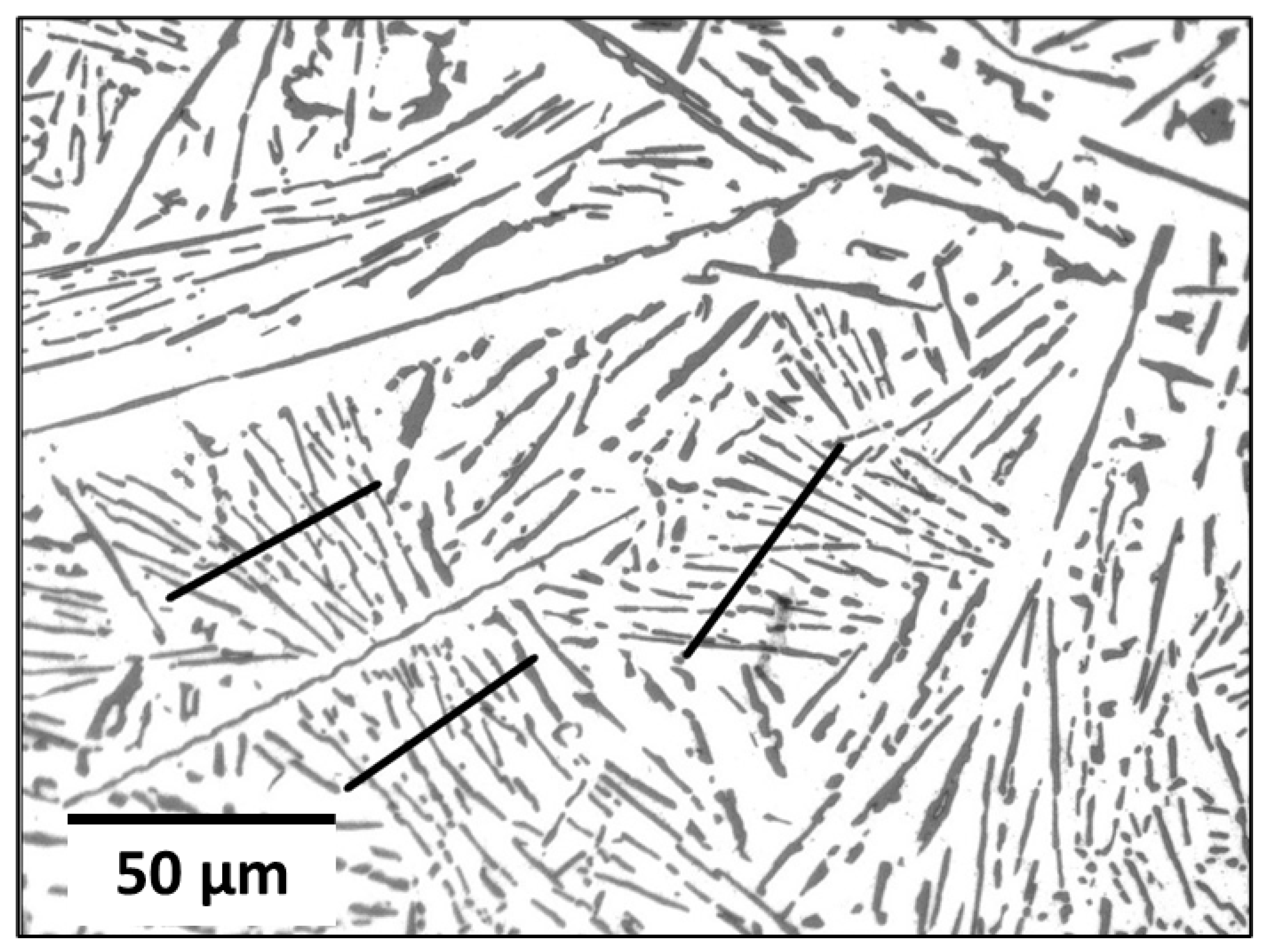
Figure 1.
Line intercept method (M = 500×).

Figure 2.
Different measured parameters in the Al–Si eutectic alloy (M = 500×).

Figure 3.
Micrographs of sample AlSi100 showing the microstructure of Al–12.6-wt%-Si alloy (I) macro- and micro-structures without magnetic stirring; (II) macro-structure under 100 mT magnetic stirring; (II.a) microstructure of primary Al at the edges of the sample; (II.b) Christmas-tree-like (CTL) segregation pattern; (II.c) primary Si arc-like segregation; (II.d) formation mechanism of the primary arc-like segregation pattern.

Figure 4.
Inter-lamellar distance measurements. (a) Non-stirred parts, Steps 1, 3, and 5, (b) stirred parts, Steps 2 and 4.
Figure 4.
Inter-lamellar distance measurements. (a) Non-stirred parts, Steps 1, 3, and 5, (b) stirred parts, Steps 2 and 4.

Figure 5.
Different eutectic-structure morphologies in the stirred parts. (a) Coarse eutectic structure grown near primary Si phase (λ = 5.2 μm). (b) Fine eutectic structure grown near primary Al phase (λ = 2.0 μm).
Figure 5.
Different eutectic-structure morphologies in the stirred parts. (a) Coarse eutectic structure grown near primary Si phase (λ = 5.2 μm). (b) Fine eutectic structure grown near primary Al phase (λ = 2.0 μm).

Figure 6.
Length of Si eutectic plate vs. magnetic induction (B), (a) below 10 μm, (b) above 10 μm.

Figure 7.
Angle distribution curves of fine eutectic Si lamella (<1 μm) of Al–Si eutectic specimens. (a) First stirring process (Steps 1 and 2). (b) Second stirring process (Steps 3 and 4).
Figure 7.
Angle distribution curves of fine eutectic Si lamella (<1 μm) of Al–Si eutectic specimens. (a) First stirring process (Steps 1 and 2). (b) Second stirring process (Steps 3 and 4).

Figure 8.
Angle distribution percentages for different size ranges. (a) Preferred angle distribution for each size range. (b) Maximum percentages of lamellae that orient in the preferred angle for each size range during the first stirring process (Steps 1 and 2). (c) Maximum percentages of lamellae that orient in the preferred angle for each size range during the second stirring process (Steps 3 and 4).


Table 1.
Magnetic intensity profile during solidification.
| Sample | B (mT) | ||||
|---|---|---|---|---|---|
| Step 1 | Step 2 | Step 3 | Step 4 | Step 5 | |
| AlSi20 | 0 | 20 | 0 | 40 | 0 |
| AlSi60 | 0 | 60 | 0 | 80 | 0 |
| AlSi100 | 0 | 100 | 0 | 120 | 0 |
| AlSi150 * | 0 | 150 | N/A | N/A | N/A |
AlSi150 *: The solidification experiments were performed in two steps for the AlSi150 sample.
Publisher’s Note: MDPI stays neutral with regard to jurisdictional claims in published maps and institutional affiliations. |
© 2022 by the authors. Licensee MDPI, Basel, Switzerland. This article is an open access article distributed under the terms and conditions of the Creative Commons Attribution (CC BY) license (https://creativecommons.org/licenses/by/4.0/).
Share and Cite
MDPI and ACS Style
Al-Omari, K.; Roósz, A.; Rónaföldi, A.; Veres, Z. Effect of Forced Melt Flow on Al–Si Eutectic-Alloy Microstructures. Crystals 2022, 12, 731. https://0-doi-org.brum.beds.ac.uk/10.3390/cryst12050731
AMA Style
Al-Omari K, Roósz A, Rónaföldi A, Veres Z. Effect of Forced Melt Flow on Al–Si Eutectic-Alloy Microstructures. Crystals. 2022; 12(5):731. https://0-doi-org.brum.beds.ac.uk/10.3390/cryst12050731
Chicago/Turabian StyleAl-Omari, Kassab, András Roósz, Arnold Rónaföldi, and Zsolt Veres. 2022. "Effect of Forced Melt Flow on Al–Si Eutectic-Alloy Microstructures" Crystals 12, no. 5: 731. https://0-doi-org.brum.beds.ac.uk/10.3390/cryst12050731
Note that from the first issue of 2016, this journal uses article numbers instead of page numbers. See further details here.