
Development of Double C-Shaped Left-Handed Metamaterial for Dual-Band Wi-Fi and Satellite Communication Application with High Effective Medium Radio and Wide Bandwidth

 , , , ,
  , and
, and
Abstract
:1. Introduction
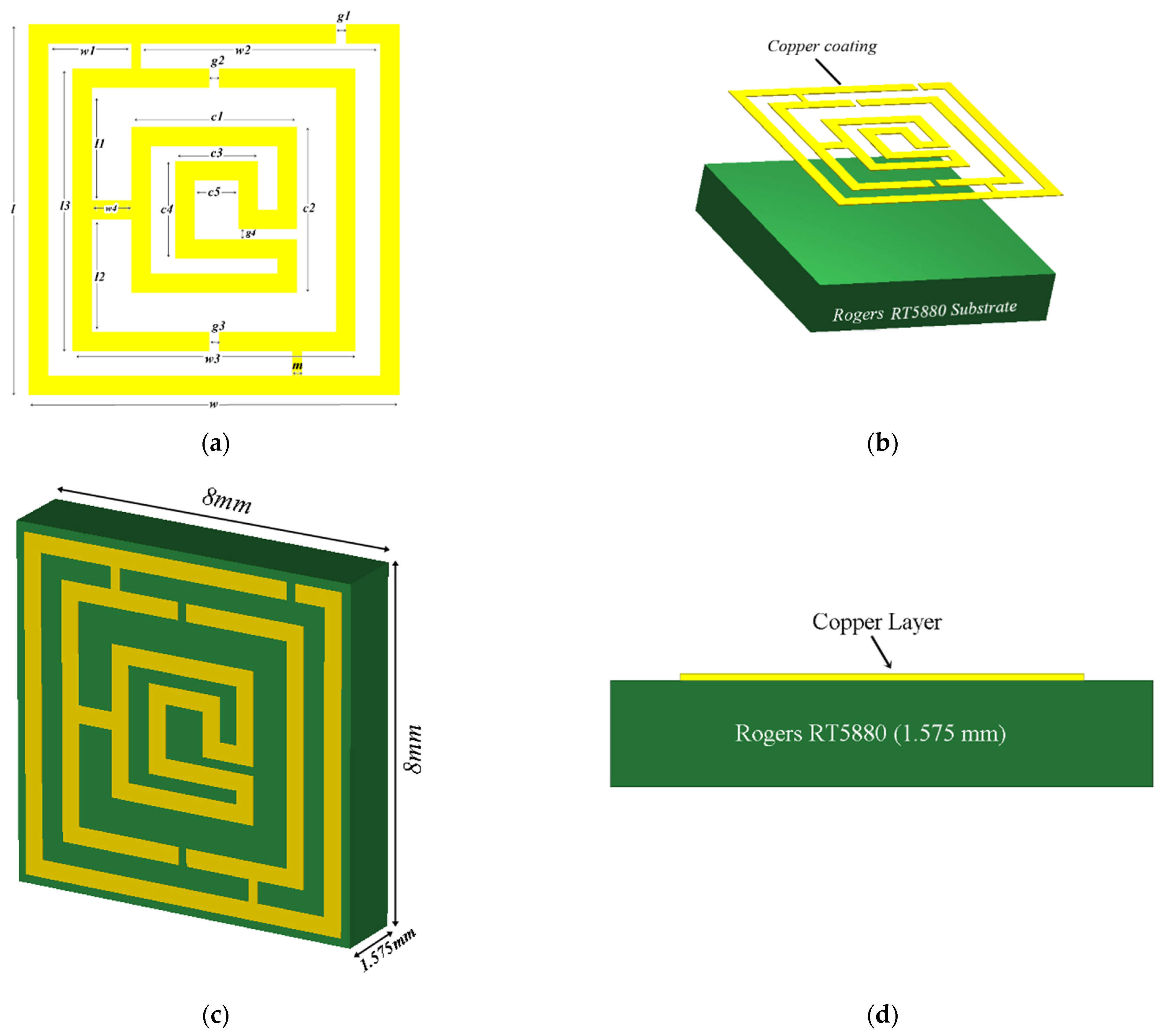
2. Design of the Metamaterial Unit Cell
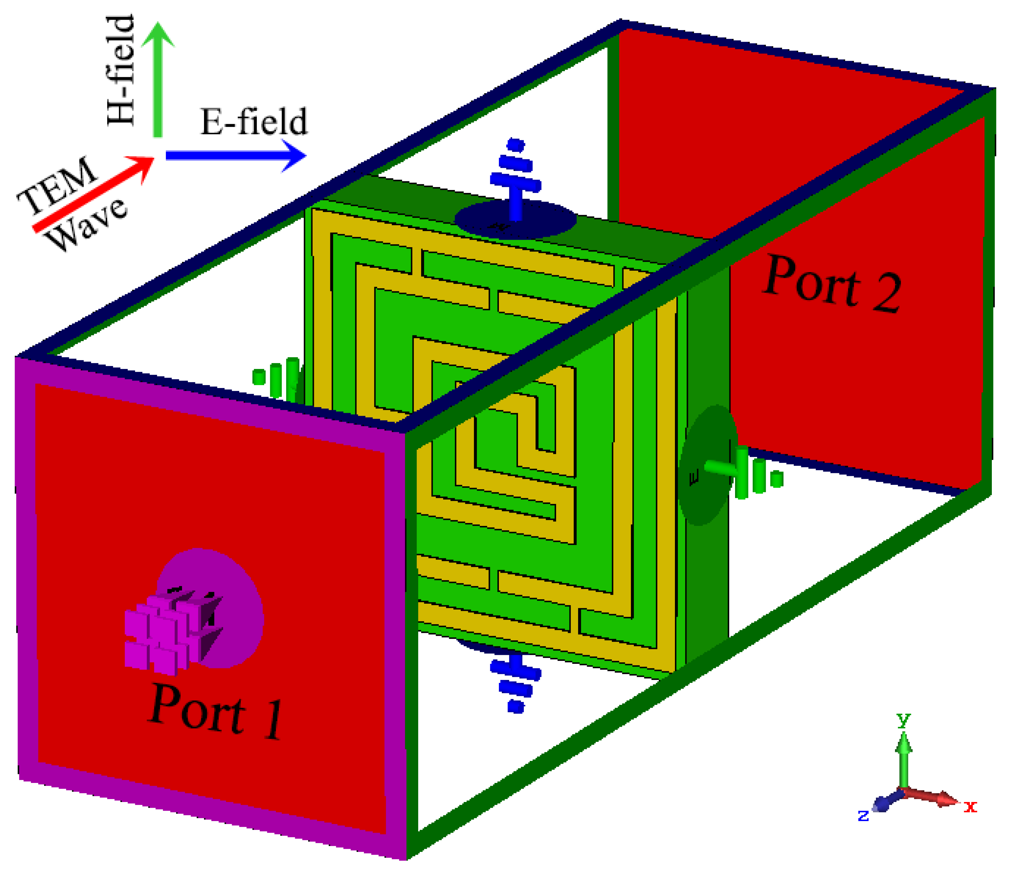
3. Metamaterial Simulation and Methodology
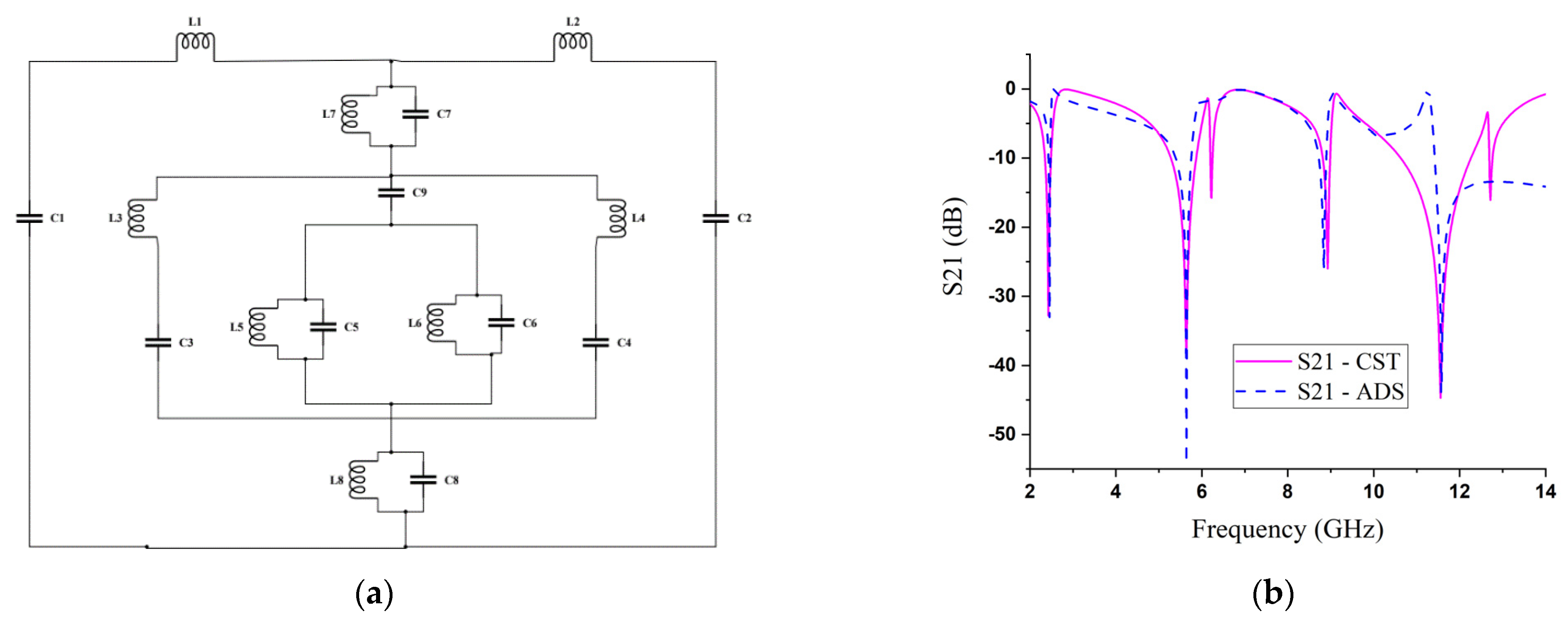
4. Equivalent Circuit and Design Analysis
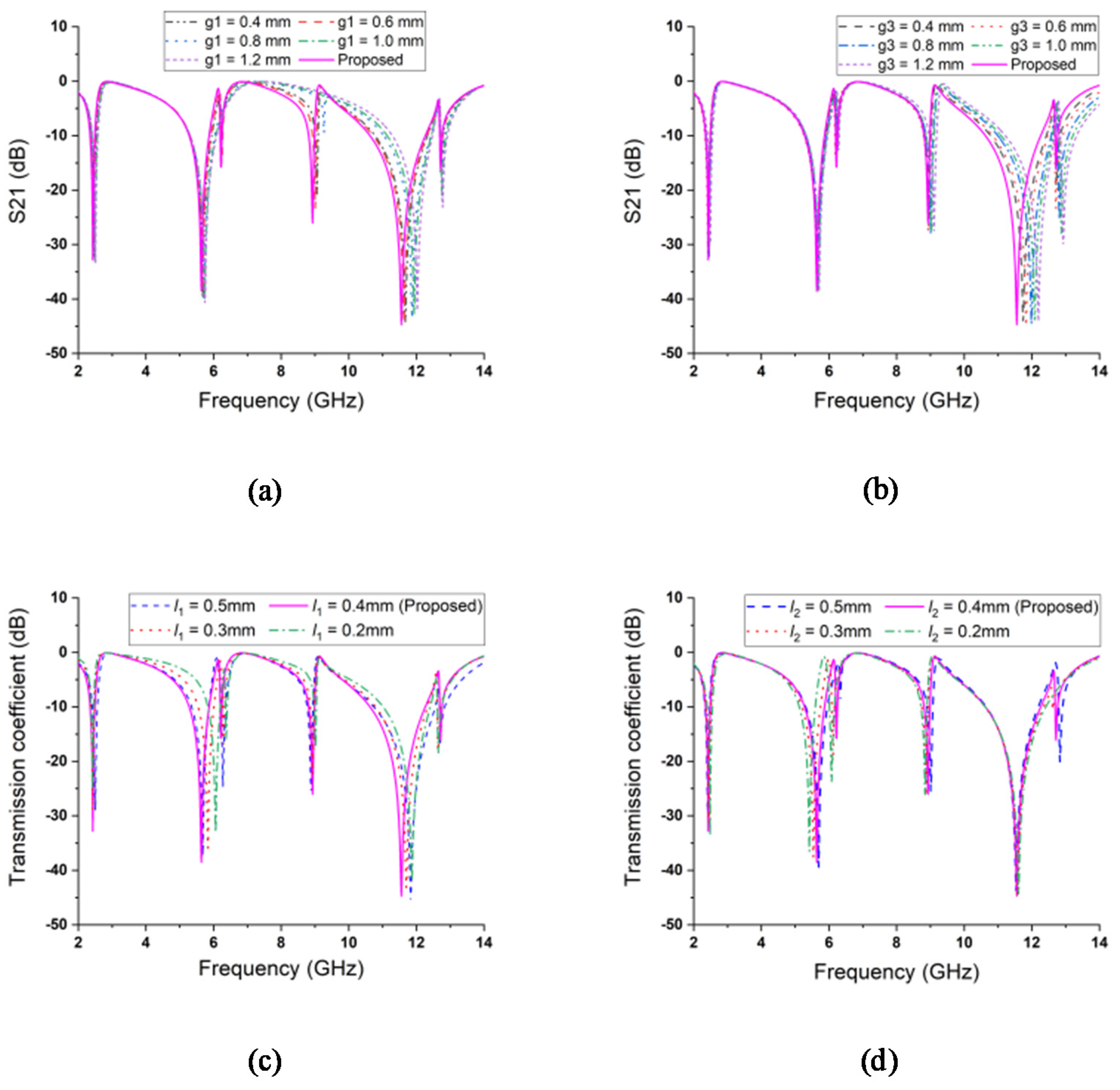
5. Parametric Study: Changing Effects of Length and Split Gaps
6. Results and Discussion
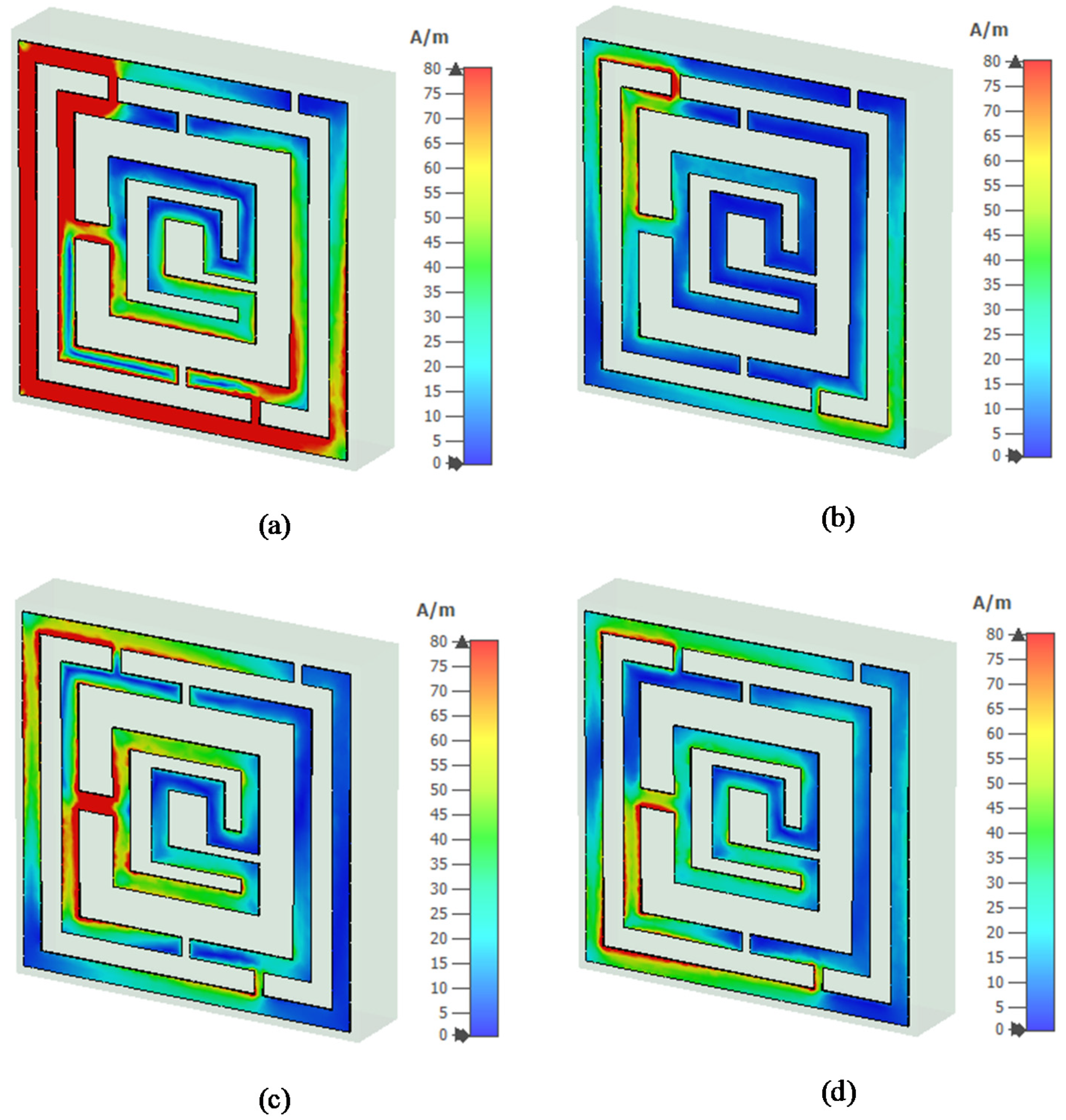
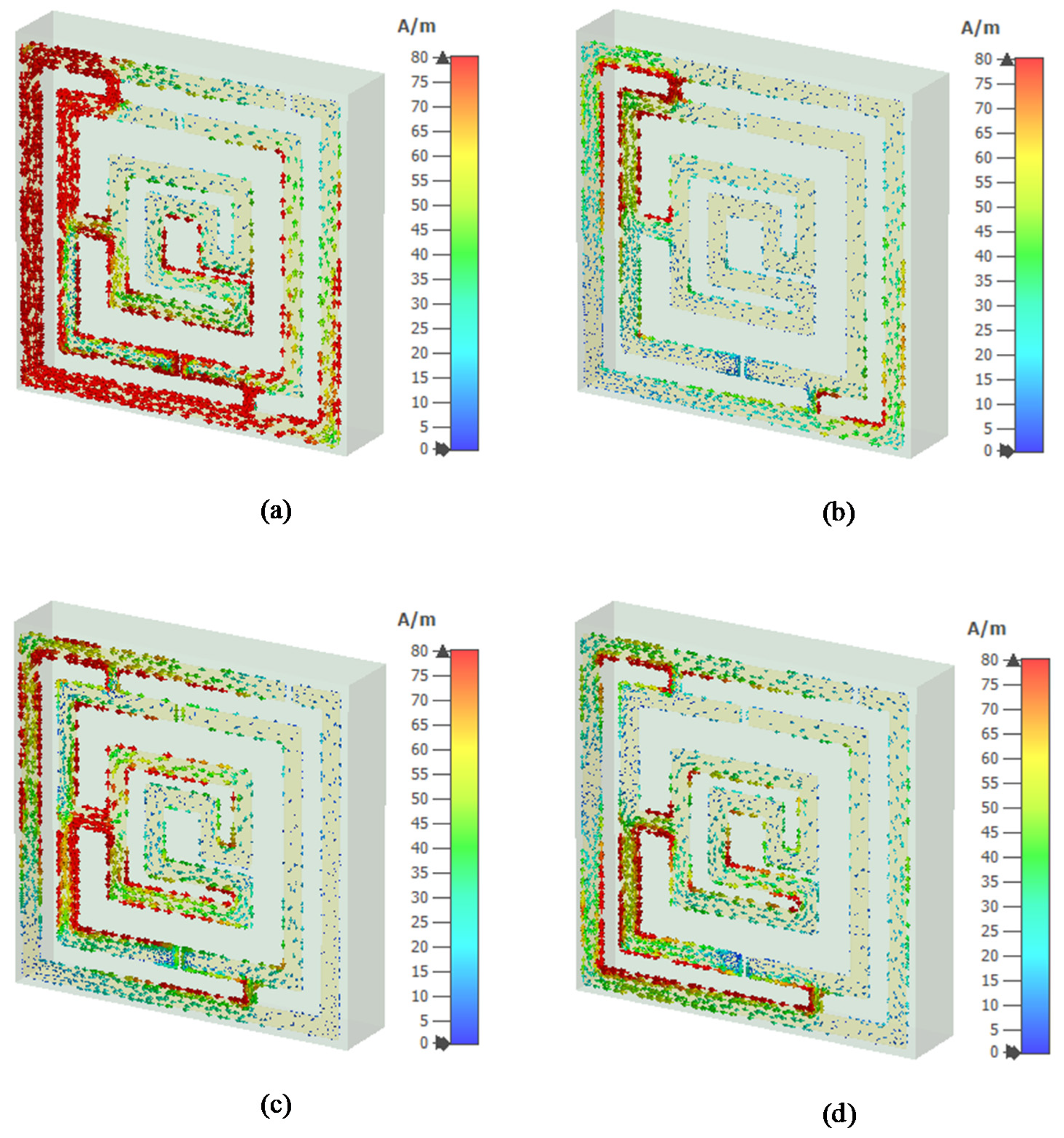
6.1. Electric Field, Magnetic Field, and Surface Current Analysis
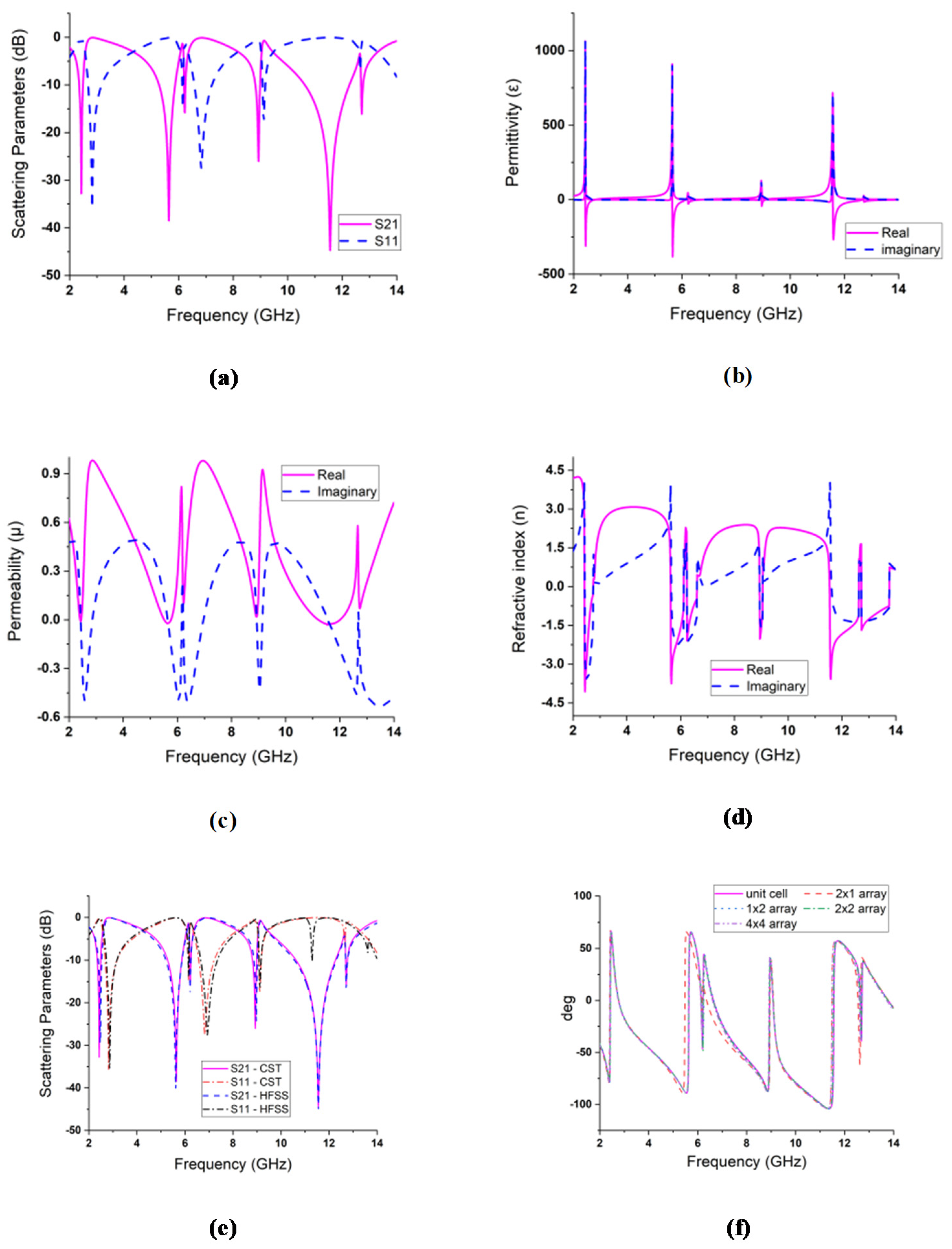
6.2. Metamaterial Unit Cell Property Extraction Analysis
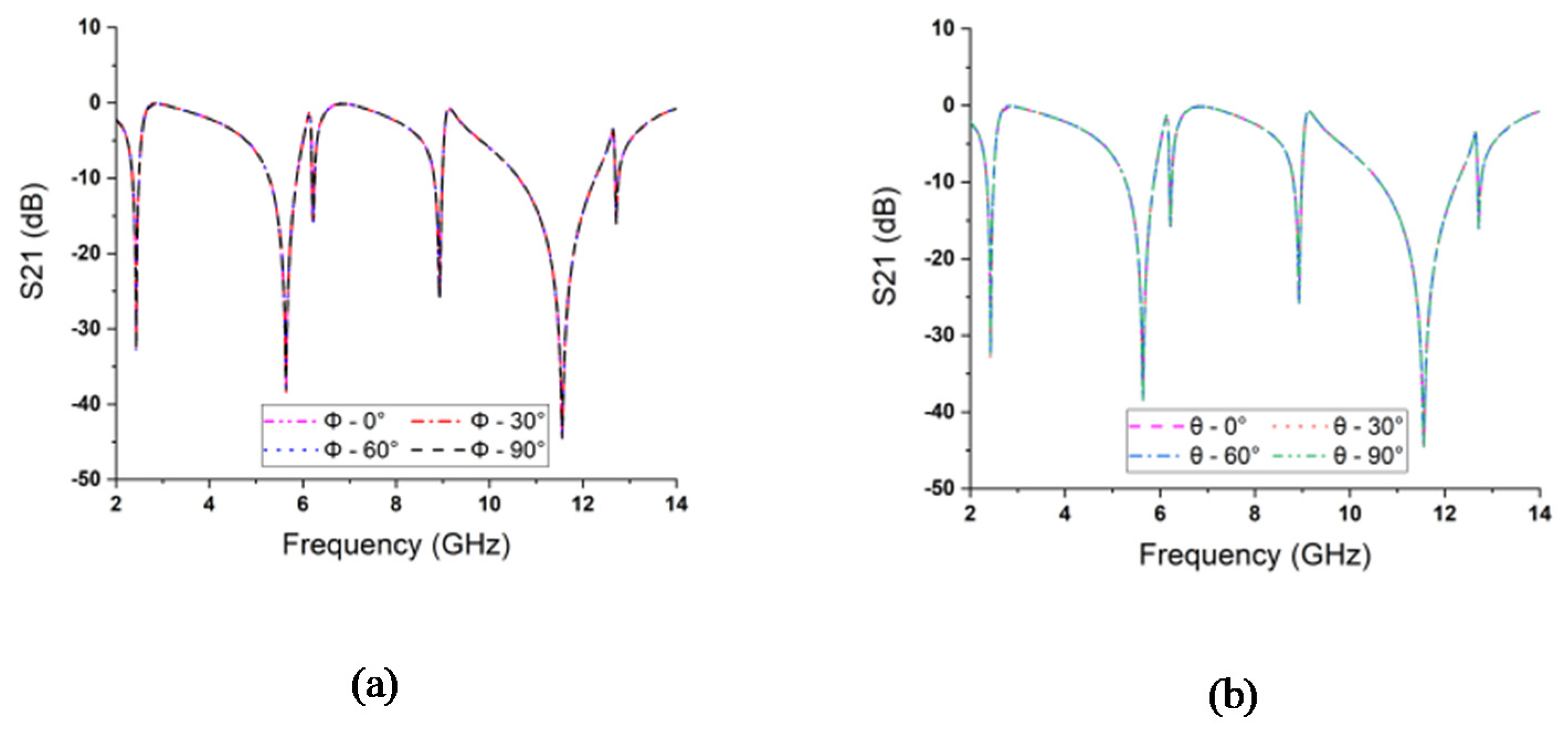
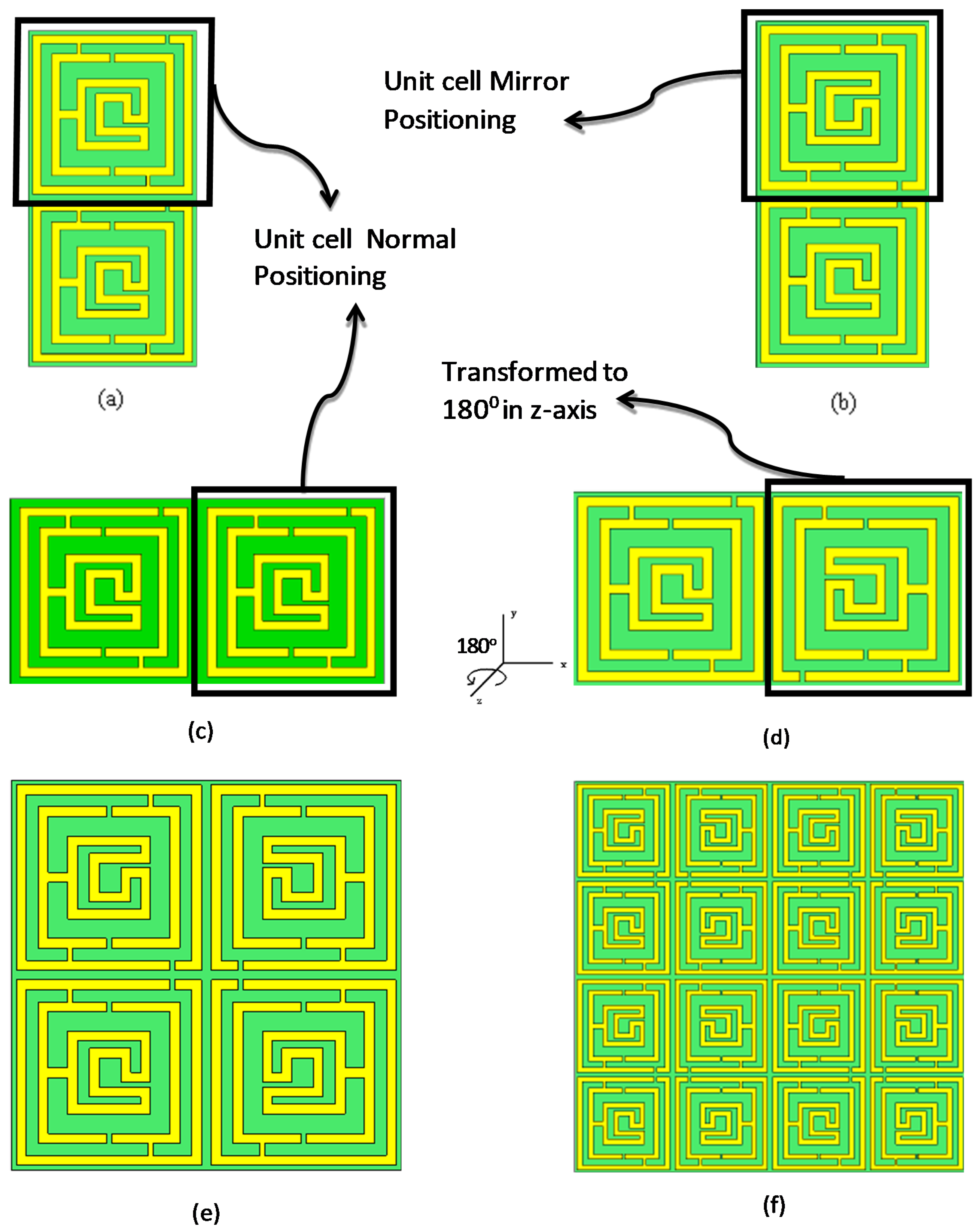
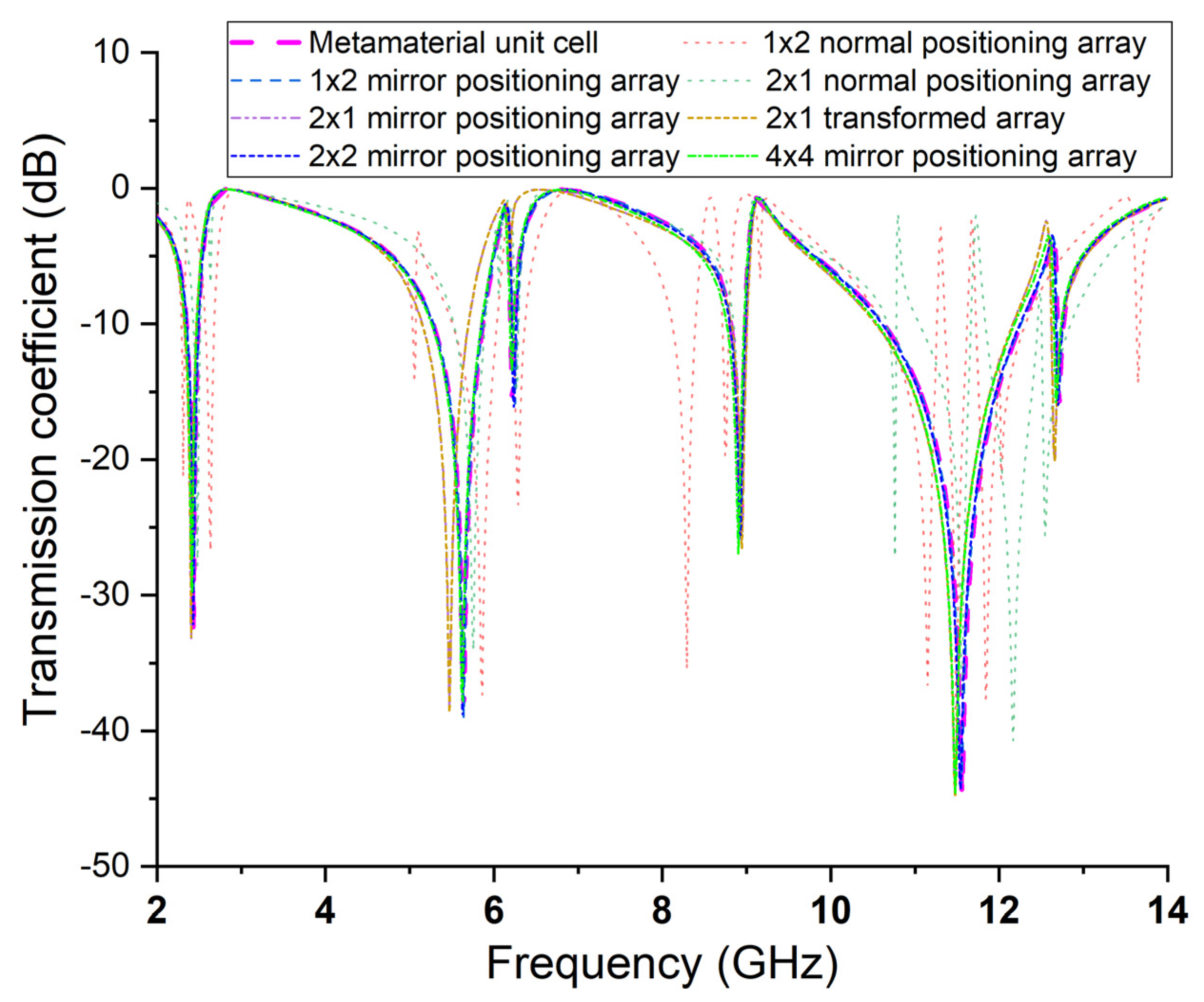
6.3. Metamaterial Array Analysis
6.4. Effective Medium Ratio (EMR) Analysis and Comparison
7. Conclusions
Author Contributions
Funding
Institutional Review Board Statement
Informed Consent Statement
Data Availability Statement
Conflicts of Interest
References
- Gibson, W.C. The Method of Moments in Electromagnetics; Chapman and Hall/CRC: Boca Raton, FL, USA, 2021. [Google Scholar]
- Veselago, V. Electrodynamics of substances with simultaneously negative and. Uspekhi Fiz. Nauk. 1967, 92, 517. [Google Scholar] [CrossRef]
- Smith, D.R.; Padilla, W.J.; Vier, D.; Nemat-Nasser, S.C.; Schultz, S. Composite medium with simultaneously negative permeability and permittivity. Phys. Rev. 2000, 84, 4184. [Google Scholar] [CrossRef] [PubMed] [Green Version]
- Smith, D.R.; Liu, R.; Cui, T.J.; Cheng, Q.; Gollub, J.N. Metamaterials for Surfaces and Waveguides. U.S. Patent S10461433B2, 29 October 2019. [Google Scholar]
- Hossain, M.; Faruque, M.R.I.; Islam, M.T. Design of a patch antenna for ultra wide band applications. Microw. Opt. Technol. Lett. 2016, 58, 2152–2156. [Google Scholar] [CrossRef]
- Sikdar, D.; Ma, Y.; Kucernak, A.R.; Edel, J.B.; Kornyshev, A.A. Nanoplasmonic Metamaterial Devices as Electrically Switchable Perfect Mirrors and Perfect Absorbers. In Proceedings of the 2019 Conference on Lasers and Electro-Optics (CLEO), San Jose, CA, USA, 5–10 May 2019; p. FM3C.5. [Google Scholar]
- Cheng, Y.; Fan, J.; Luo, H.; Chen, F. Dual-band and high-efficiency circular polarization convertor based on anisotropic metamaterial. IEEE Access 2019, 8, 7615–7621. [Google Scholar] [CrossRef]
- Wang, Q.; Cheng, Y. Compact and low-frequency broadband microwave metamaterial absorber based on meander wire structure loaded resistors. AEU-Int. J. Electron. Commun. 2020, 120, 153198. [Google Scholar] [CrossRef]
- Yin, X.; Zhu, H.; Guo, H.; Deng, M.; Xu, T.; Gong, Z.; Li, X.; Hang, Z.H.; Wu, C.; Li, H. Hyperbolic Metamaterial Devices for Wavefront Manipulation. Laser Photonics Rev. 2019, 13, 1800081. [Google Scholar] [CrossRef] [Green Version]
- Islam, M.; Islam, M.T.; Faruque, M.R.I.; Samsuzzaman, M.; Misran, N.; Arshad, H. Microwave imaging sensor using compact metamaterial UWB antenna with a high correlation factor. Materials 2015, 8, 4631–4651. [Google Scholar] [CrossRef] [Green Version]
- Faruque, M.; Islam, M.; Ali, M. A new design of metamaterials for SAR reduction. Meas. Sci. Rev. 2013, 13, 70. [Google Scholar] [CrossRef]
- Yao, Y.; Liao, Z.; Liu, Z.; Liu, X.; Zhou, J.; Liu, G.; Yi, Z.; Wang, J. Recent progresses on metamaterials for optical absorption and sensing: A review. J. Phys. D Appl. Phys. 2021, 54, 113002. [Google Scholar] [CrossRef]
- Alam, M.J.; Ahamed, E.; Faruque, M.R.I.; Islam, M.T.; Tamim, A.M. Left-handed metamaterial bandpass filter for GPS, Earth Exploration-Satellite and WiMAX frequency sensing applications. PLoS ONE 2019, 14, e0224478. [Google Scholar]
- Mukherjee, S.; Su, Z.; Udpa, L.; Udpa, S.; Tamburrino, A. Enhancement of Microwave Imaging Using a Metamaterial Lens. IEEE Sens. J. 2019, 19, 4962–4971. [Google Scholar] [CrossRef]
- Qiu, J.; Liu, X.; Liang, Z.; Zhu, J. Ultra-wideband perfect reflection and tunneling by all-dielectric metamaterials. Opt. Lett. 2021, 46, 849–852. [Google Scholar] [CrossRef] [PubMed]
- Dănilă, O.; Bărar, A.; Vlădescu, M.; Mănăilă-Maximean, D. An Extended k-Surface Framework for Electromagnetic Fields in Artificial Media. Materials 2021, 14, 7842. [Google Scholar] [CrossRef] [PubMed]
- Danila, O.; Manaila-Maximean, D. Bifunctional metamaterials using spatial phase gradient architectures: Generalized reflection and refraction considerations. Materials 2021, 14, 2201. [Google Scholar] [CrossRef] [PubMed]
- Yu, N.; Genevet, P.; Kats, M.A.; Aieta, F.; Tetienne, J.-P.; Capasso, F.; Gaburro, Z. Light propagation with phase discontinuities: Generalized laws of reflection and refraction. Science 2011, 334, 333–337. [Google Scholar] [CrossRef] [PubMed] [Green Version]
- Islam, S.; Hasan, M.; Faruque, M.R.I. A new metamaterial-based wideband rectangular invisibility cloak. Appl. Phys. A 2018, 124, 160. [Google Scholar] [CrossRef]
- Idrus, I.N.; Faruque, M.R.I.; Abdullah, S.; Khandaker, M.U.; Tamam, N.; Sulieman, A. An Oval-Square Shaped Split Ring Resonator Based Left-Handed Metamaterial for Satellite Communications and Radar Applications. Micromachines 2022, 13, 578. [Google Scholar] [CrossRef]
- Ahamed, E.; Tamim, A.M.; Faruque, M.R.I.; Sifat, R.; Islam, M.T. Reconfigurable THz metamaterial filter based on binary response for information processing system. Front. Phys. 2021, 9, 79–87. [Google Scholar] [CrossRef]
- Silalahi, H.M.; Chen, Y.-P.; Shih, Y.-H.; Chen, Y.-S.; Lin, X.-Y.; Liu, J.-H.; Huang, C.-Y. Floating terahertz metamaterials with extremely large refractive index sensitivities. Photonics Res. 2021, 9, 1970–1978. [Google Scholar] [CrossRef]
- Wang, J.; Tian, H.; Li, S.; Li, L.; Wang, G.; Gao, J.; Guo, W.; Zhou, Z. Efficient terahertz polarization conversion with hybrid coupling of chiral metamaterial. Opt. Lett. 2020, 45, 1276–1279. [Google Scholar] [CrossRef]
- Xu, R.; Xu, X.; Yang, B.-R.; Gui, X.; Qin, Z.; Lin, Y.-S. Actively logical modulation of MEMS-based terahertz metamaterial. Photonics Res. 2021, 9, 1409–1415. [Google Scholar] [CrossRef]
- Faruque, M.R.I.; Hossain, M.J.; Islam, S.S.; Jamlos, M.F.B.; Islam, M.T. Design and analysis of a new double C-shaped miniaturized metamaterial for multiband applications. Appl. Phys. A 2017, 123, 310. [Google Scholar] [CrossRef]
- Marathe, D.; Kulat, K. A compact triple-band negative permittivity metamaterial for C, X-band applications. Int. J. Antennas Propag. 2017, 2017, 7515264. [Google Scholar] [CrossRef] [Green Version]
- Tamim, A.M.; Faruque, M.R.I.; Alam, M.J.; Islam, S.S.; Islam, M.T. Split ring resonator loaded horizontally inverse double L-shaped metamaterial for C-, X-and Ku-Band Microwave applications. Results Phys. 2019, 12, 2112–2122. [Google Scholar] [CrossRef]
- Afsar, M.S.U.; Faruque, M.R.I.; Khandaker, M.U.; Alqahtani, A.; Bradley, D.A. A New Compact Split Ring Resonator Based Double Inverse Epsilon Shaped Metamaterial for Triple Band Satellite and Radar Communication. Crystals 2022, 12, 520. [Google Scholar] [CrossRef]
- Sifat, R.; Faruque, M.R.I.; Ahmed, E.; Islam, M.T.; Khandaker, M.U. Electric field controlled cohesive symmetric hook-C shape inspired metamaterial for S-band application. Chin. J. Phys. 2020, 68, 28–38. [Google Scholar] [CrossRef]
- Islam, M.R.; Islam, M.T.; Moniruzzaman, M.; Samsuzzaman, M.; Bais, B.; Arshad, H.; Muhammad, G. Square enclosed circle split ring resonator enabled epsilon negative (ENG) near zero index (NZI) metamaterial for gain enhancement of multiband satellite and radar antenna applications. Results Phys. 2020, 19, 103556. [Google Scholar] [CrossRef]
- Islam, M.T.; Moniruzzaman, M.; Alam, T.; Samsuzzaman, M.; Razouqi, Q.A.; Almutairi, A.F. Realization of frequency hopping characteristics of an epsilon negative metamaterial with high effective medium ratio for multiband microwave applications. Sci. Rep. 2021, 11, 16898. [Google Scholar] [CrossRef]
- Xu, S.; Li, Y.; Gao, Y.; Liu, Y.; Gačanin, H. Opportunistic coexistence of LTE and WiFi for future 5G system: Experimental performance evaluation and analysis. IEEE Access 2017, 6, 8725–8741. [Google Scholar] [CrossRef]
- Chung, M.-A.; Hsiao, C.-W. Dual-Band 6 × 6 MIMO Antenna System for Glasses Applications Compatible with Wi-Fi 6E and 7 Wireless Communication Standards. Electronics 2022, 11, 806. [Google Scholar] [CrossRef]
- Hirtenfelder, F. Effective antenna simulations using CST MICROWAVE STUDIO®. In Proceedings of the 2007 2nd International ITG Conference on Antennas, Munich, Germany, 28–30 March 2007; p. 239. [Google Scholar]
- Chen, X.; Grzegorczyk, T.M.; Wu, B.-I.; Pacheco, J., Jr.; Kong, J.A. Robust method to retrieve the constitutive effective parameters of metamaterials. Phys. Rev. E 2004, 70, 016608. [Google Scholar] [CrossRef] [PubMed] [Green Version]
- Ahamed, E.; Faruque, M.R.I.; Tamim, A.M.; Islam, M.T.; Mansor, M.F.B.; Ahmmed, M.B. Enhancement of magnetic field intensity with a left-handed metamaterial tunnel resonator for obstacle sensing. Chin. J. Phys. 2021, 70, 91–105. [Google Scholar] [CrossRef]
- Alam, M.; Ahamed, E.; Faruque, M.; Hossain, M.; Islam, M. Aztec shape metamaterial-based bandpass filter for C, X and Ku-band applications. Earth Environ. Sci. 2019, 228, 012019. [Google Scholar] [CrossRef]
- Taflove, A.; Hagness, S.C.; Piket-May, M. Computational electromagnetics: The finite-difference time-domain method. In The Electrical Engineering Handbook; Chen, E., Ed.; Academic Press: Burlington, NJ, USA, 2005; Volume 3. [Google Scholar]
- Paul, C.R. Inductance: Loop and Partial; John Wiley & Sons: Hoboken, NJ, USA, 2011. [Google Scholar]
- Bayliss, A.; Goldstein, C.I.; Turkel, E. An iterative method for the Helmholtz equation. J. Comput. Phys. 1983, 49, 443–457. [Google Scholar] [CrossRef]
- Ahamed, E.; Faruque, M.R.I.; Mansor, M.F.B.; Islam, M.T. Polarization-dependent tunneled metamaterial structure with enhanced fields properties for X-band application. Results Phys. 2019, 15, 102530. [Google Scholar] [CrossRef]
- Sun, S.; Miscuglio, M.; Ma, X.; Ma, Z.; Shen, C.; Kayraklioglu, E.; Anderson, J.; El Ghazawi, T.; Sorger, V.J. Induced homomorphism: Kirchhoff’s law in photonics. Nanophotonics 2021, 10, 1711–1721. [Google Scholar] [CrossRef]


| Parameter | a & b | l & w | l1 & l2 | l3 | l4 | w1 & c3 | w2 |
| Value | 8 | 7.6 | 2.3 | 5.8 | 3.4 | 1.7 | 4.9 |
| Parameter | w3 | w4 | g1,g2,g3,g4 | c1 & c2 | c4 | c5 | m |
| Value | 5.8 | 0.8 | 0.2 | 3.4 | 2 | 0.9 | 0.2 |
 |  |  |  |  | |
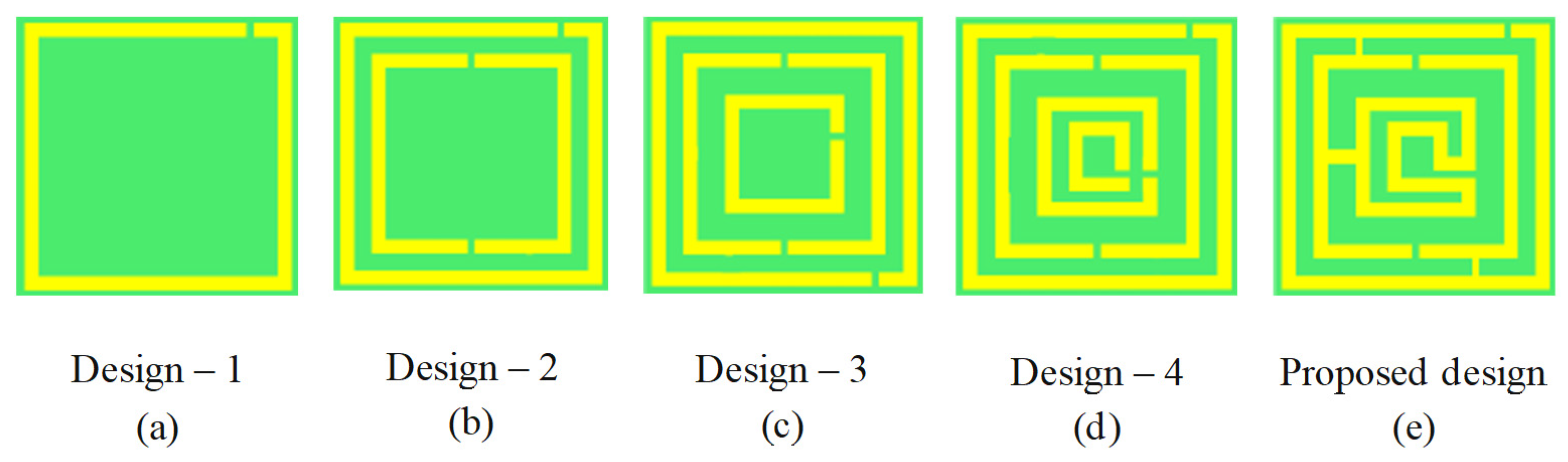
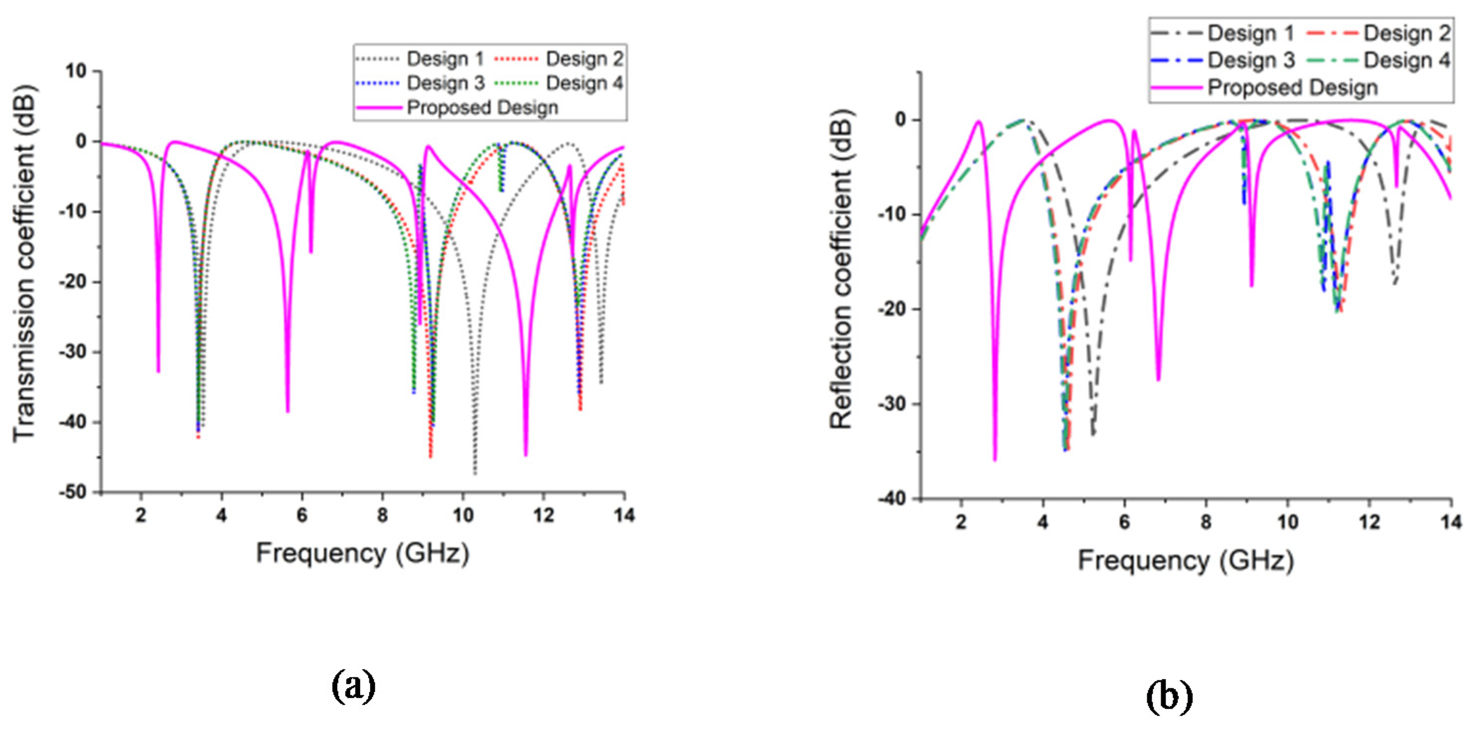
| Structure | Design 1 | Design 2 | Design 3 | Design 4 | Proposed design |
| Resonance frequencies | 3.53, 10.29, 13.42 GHz | 3.41, 9.19, 12.9 GHz | 3.41, 8.72, 9.25, 12.87 GHz | 3.43, 8.77, 9.25, 12.85 GHz | 2.4, 5.6, 8.93, 11.5 GHz |
| Magnitude in dB | −40.79, −47.37, −34.61 | −42.49, −44.98, −38.36 | −41.38, −35.89, −35.68, −40.44 | −39.9, −35.11, −39.9, −23.43 | −32.27, −38.28, −25.99, −44.7 |
| Bandwidth Span (under −10 dB) | 3.25–3.8, 9.38–11.1, 13.2–13.8 | 3.1–3.6, 8.3–9.8, 12.5–13.36 | 3.18–3.6, 8.27–8.88, 9.0–9.7, 12.55–13.19 | 3.19–3.6, 8.28–8.87, 9.0–9.7, 12.5–13.15 | 2.3–2.49, 5.27–5.87, 8.81–8.98, 10.61–12.26 |
| Capacitor | Value (pF) | Inductor | Value (nH) | Capacitor | Value (pF) | Inductor | Value (nH) |
|---|---|---|---|---|---|---|---|
| C1 | 0.2 | L1 | 0.5 | C6 | 1.45 | L6 | 1.61 |
| C2 | 1.5 | L2 | 0.258 | C7 | 0.775 | L7 | 0.85 |
| C3 | 0.85 | L3 | 1.33 | C8 | 0.76 | L8 | 0.408 |
| C4 | 1.8 | L4 | 4.42 | C9 | 4.405 | ||
| C5 | 1.02 | L5 | 1.5 |
| References | Year | Shape | Dimensions (mm) | Resonance Frequencies (GHz) | EMR | Frequency Bands |
|---|---|---|---|---|---|---|
| [25] | 2017 | Double C | 12 × 12 | 3.36, 8.57, 11.57 | 7.42 | S, C, and X |
| [26] | 2017 | Delta loop | 6 × 6 | 4.3, 7.6, 9.8 | 11.5 | C and X |
| [27] | 2019 | Double L | 10 × 10 | 7.69, 8.47, 12.04, 13.14 | 3.9 | C, X and Ku |
| [28] | 2020 | Inverse-epsilon | 10 × 10 | 2.38, 4.55, 9.42 | 12.61 | S, C and X |
| [29] | 2020 | Hook-C shape | 8 × 8 | 2.93 | 12.78 | S-band |
| [30] | 2020 | Square-Circle | 8 × 8 | 2.6, 6.3, 9.3 | 14.3 | S, C, and X |
| [31] | 2021 | Semi-Circle | 8 × 8 | 2.48, 4.28, 9.36, 13.7 | 15.1 | C, S, X and Ku |
| Proposed | 2022 | Double C shaped | 8 × 8 | 2.4, 5.64, 8.93, 11.5 | 15.6 | S, C, and X |
Publisher’s Note: MDPI stays neutral with regard to jurisdictional claims in published maps and institutional affiliations. |
© 2022 by the authors. Licensee MDPI, Basel, Switzerland. This article is an open access article distributed under the terms and conditions of the Creative Commons Attribution (CC BY) license (https://creativecommons.org/licenses/by/4.0/).
Share and Cite
Sifat, R.; Faruque, M.R.I.; Hossain, M.B.; Abdullah, M.; Islam, M.T.; Khandaker, M.U.; Tamam, N.; Sulieman, A. Development of Double C-Shaped Left-Handed Metamaterial for Dual-Band Wi-Fi and Satellite Communication Application with High Effective Medium Radio and Wide Bandwidth. Crystals 2022, 12, 836. https://0-doi-org.brum.beds.ac.uk/10.3390/cryst12060836
Sifat R, Faruque MRI, Hossain MB, Abdullah M, Islam MT, Khandaker MU, Tamam N, Sulieman A. Development of Double C-Shaped Left-Handed Metamaterial for Dual-Band Wi-Fi and Satellite Communication Application with High Effective Medium Radio and Wide Bandwidth. Crystals. 2022; 12(6):836. https://0-doi-org.brum.beds.ac.uk/10.3390/cryst12060836
Chicago/Turabian StyleSifat, Rasheduzzaman, Mohammad Rashed Iqbal Faruque, Md Bellal Hossain, Mardina Abdullah, Mohammad Tariqul Islam, Mayeen Uddin Khandaker, Nissren Tamam, and Abdelmoneim Sulieman. 2022. "Development of Double C-Shaped Left-Handed Metamaterial for Dual-Band Wi-Fi and Satellite Communication Application with High Effective Medium Radio and Wide Bandwidth" Crystals 12, no. 6: 836. https://0-doi-org.brum.beds.ac.uk/10.3390/cryst12060836