Article

Investigation on Friction Stir Welding Parameters: Mechanical Properties, Correlations and Corrosion Behaviors of Aluminum/Titanium Dissimilar Welds

1
Indian Institute of Science, Bengaluru 560012, India
2
Arbegast Materials Processing and Joining Laboratory (AMP), South Dakota School of Mines and Technology, Rapid City, SD 57701, USA
3
Laboratory of Mechanical Properties of Nanostructured and Heat-Resistant Materials, Belgorod State National Research University, Belgorod 308034, Russia
*
Author to whom correspondence should be addressed.
Submission received: 18 February 2024 / Revised: 12 March 2024 / Accepted: 24 March 2024 / Published: 26 March 2024
(This article belongs to the Special Issue Microstructure and Mechanical Properties of Welding Joints)

Abstract

:
In industrial applications, welding of dissimilar metals such as aluminum (Al) and titanium (Ti) is a prerequisite for the development of hybrid components with improved mechanical and corrosion properties. However, dissimilar welding of the Al/Ti system is highly challenging due to differences in the physical and thermal properties of the two materials. In the present investigation, an attempt has been made to fabricate a dissimilar friction stir weld (FSW) of commercially pure Al and Ti and to elucidate the mechanism associated with superior joint formation. The process parameters, such as tool rotation speed, traverse speed and tool offset position have been optimized using Taguchi’s optimization technique. A detailed investigation of the weld with optimum process parameters has been carried out to reveal the mechanism of joint formation. The superior mechanical properties (24% higher ultimate tensile strength and 10% higher ductility than that of base Al) of the weld are attributed to the fabrication of a defect-free joint, formation of intercalated particles and an Al/Ti interlocking interface, homogeneous distribution of fine second-phase (Ti and/or intermetallics) particles in the weld nugget, reduction in the evolution of brittle Al3Ti intermetallic compounds (IMCs) and recrystallization and grain refinement of Al in the weld nugget. The potentio-dynamic polarization test indicated that the optimized Al/Ti weld has ~47% higher corrosion resistance than Al; it had a very mild corrosion attack due to the homogeneous dispersion of fine particles. The method and mechanism could have an immense influence on any dissimilar weld and metal matrix composites, improving their mechanical properties and corrosion resistance.

1. Introduction

The steadily growing requirement of lower greenhouse gas emissions and energy saving has resulted in the utilization of light-weight components and structures in the automobile and aerospace industries. The utilization of hybrid structures is on the rise, leading to the necessity of adequate joining processes for dissimilar materials. Joining of Al and Ti has been extensively researched due to their complementary properties. However, conventional fusion welding techniques, for example, diffusion, explosive, electron beam, laser, etc., face challenges in joining these materials due to their significant mismatch in physical and thermal properties [1]. In contrast to conventional welding techniques, laser welding finds extensive application in joining dissimilar metals due to its elevated thermal density, concentrated heat, rapid processing speed, minimal thermal deformation, and reduced environmental impact [2,3]. Various adjustments have been implemented to fine-tune processing parameters, addressing challenges related to localized melting and distortion [2,4]. These challenges result in complications such as limited mutual solubility, porosity formation, and solidification cracking during fusion welding of Al/Ti joints [5]. In addition, the evolution of intermetallic compounds (IMCs) such as Al3Ti, AlTi and Ti3Al was found to be continuous and thick during the fusion welding process. Kar et al. [6] examined the kinetics of formation of IMCs during the solid-state reaction of solid Ti and Al. Their results indicated the formation of IMCs at the interface due to the thermodynamic and kinetic considerations involved in reaction and diffusion. Their formation can lead to brittleness and negative impacts on the weld properties if they are not distributed homogeneously. However, if the IMCs are uniformly distributed at the weld interface, they can act as a dispersoid and help improve the mechanical and corrosion properties of the weld [7]. Therefore, controlling the formation of IMCs and their uniform distribution at the joint interface are essential prerequisites to achieving a sound bonding between Al and Ti.
Traditional fusion welding techniques such as arc and laser heating have been proven to be inappropriate to meet these criteria [8]. In this context, friction stir welding (FSW)—a relatively new ‘green welding’ technology invented at The Welding Institute (United Kingdom)—seems promising, as it permits welding of dissimilar materials in the solid state [9]. Also, FSW has demonstrated great potential in restricting the growth of a continuous and thick layer of IMCs due to its unique features of mechanical stirring and mixing of particles at the joint interface [10]. The key processing parameters influencing joint characteristics were found to be tool rotational speed, welding speed, plunge depth and tool offset position. The optimum FSW parameters for attaining a sound weld between Al and Ti have been investigated by several researchers [11,12]. Choi et al. [13] optimized the tool offset position and tool rotation speed to obtain a sound dissimilar butt joint of pure Al and pure Ti using the FSW process. They achieved ~80% of the ultimate tensile strength (UTS) value of the base metal (i.e., pure Al), which was attributed to a reduction in the formation of IMCs on lowering the tool offset position from 0.2 mm to 0.1 mm. Most notably, Wei and co-workers have demonstrated the feasibility of producing FSW lap joints of Al 1060 and Ti-6Al-4V with 100% joint efficiency using a rotating burr pin cutting tool [14]. The outstanding joint efficiency achieved in their study was attributed to a combination of intense mechanical mixing of Al, Ti and Al3Ti particles along with strong metallurgical bonding at the interface. Kar et al. [15] studied the interface properties of friction stir welded pure Al and pure Ti and found that the extent of mixing was not symmetrical in the weld. Further, they conducted a detailed microstructural analysis of the weld nugget region to understand the reason for such inhomogeneous distribution, as it can impact the mechanical properties of the weld.
Regardless of the promising results obtained related to the mechanical properties and interfacial features of Al/Ti joints in FSW, there is very little information about the corrosion behavior of this system. In general, corrosion occurs preferentially on the Al side of the Al/Ti joint, as the corrosion potential of Al (−0.5 V) is ~60% lower than that of Ti (~−0.2 V). Because of this relatively lower corrosion potential of Al, the joint strength of Al/Ti will be affected and joint failure may occur. Therefore, it is mandatory to regulate the corrosion behavior of Al/Ti FSW joints, keeping in mind the overall service performance. Recently, Vacchi et al. [16] have friction spot welded lap joints of AA6181-T4/Ti-6Al-4V and investigated their surface corrosion behavior. They have reported that the Al side was found to be highly corrosive, with large preferential sites for pitting corrosion. They have also suggested that the intensity of corrosion attack reduced in the weld nugget region due to the presence of small precipitates. A similar behavior was recorded by Gharavi et al. [17] on evaluating the corrosion behavior of lap joints of the AA6061-T6 alloy produced by the FSW technique. According to the above-mentioned reports, FSW of Al/Ti alloy showed profound formation of intermetallic constituent particles, which had further intensified galvanic corrosion coupling and decreased its corrosion resistance. However, it is worth mentioning that in above studies, the joints of Al and Ti were produced by choosing random parameters. Therefore, it is important to investigate the corrosion behavior of Al/Ti FSW joints and identify the optimum FSW parameters for this system to ensure the overall service performance.
Given the above context and the scarcity of studies, the objective of the present investigation was to understand the effect of optimized FSW process parameters on the joint quality and corrosion resistance of dissimilar welded joints of Al and Ti. The optimization of process parameters was conducted using Taguchi’s approach in the design of experiments. The microstructural characterization of the optimized weld was conducted to understand the evolution of microstructure, phases and intermetallics at the joint interface. The study also focused on evaluating the corrosion behavior of the welded joint, as it is a critical aspect in ensuring the reliability and performance of the joint in service. The results of the investigation provide valuable insights for the development of Al/Ti joints with improved mechanical and corrosion properties, which could find potential applications in various industries such as aerospace, automotive and marine.

2. Experimental Section

2.1. Materials

The study uses commercially available pure plates of Aluminum (Al) and Titanium (Ti) with a thickness of 4 mm. The chemical compositions and mechanical properties of the starting materials are provided in Table 1 and Table 2, respectively. The plates are dissected and machined into sizes of 200 mm × 70 mm in order to perform butt-welding using FSW (friction stir welding). The surfaces of the cut samples are grounded with grit papers to remove any oxide layers, which may impede the welding process. The samples are then cleaned using ethanol before welding.
The plates were dissected and machined into sizes of 200 mm × 70 mm in order to perform butt-welding using FSW. The surfaces of the cut samples were grounded with grit papers to remove any oxide layers and then cleaned using ethanol before welding.

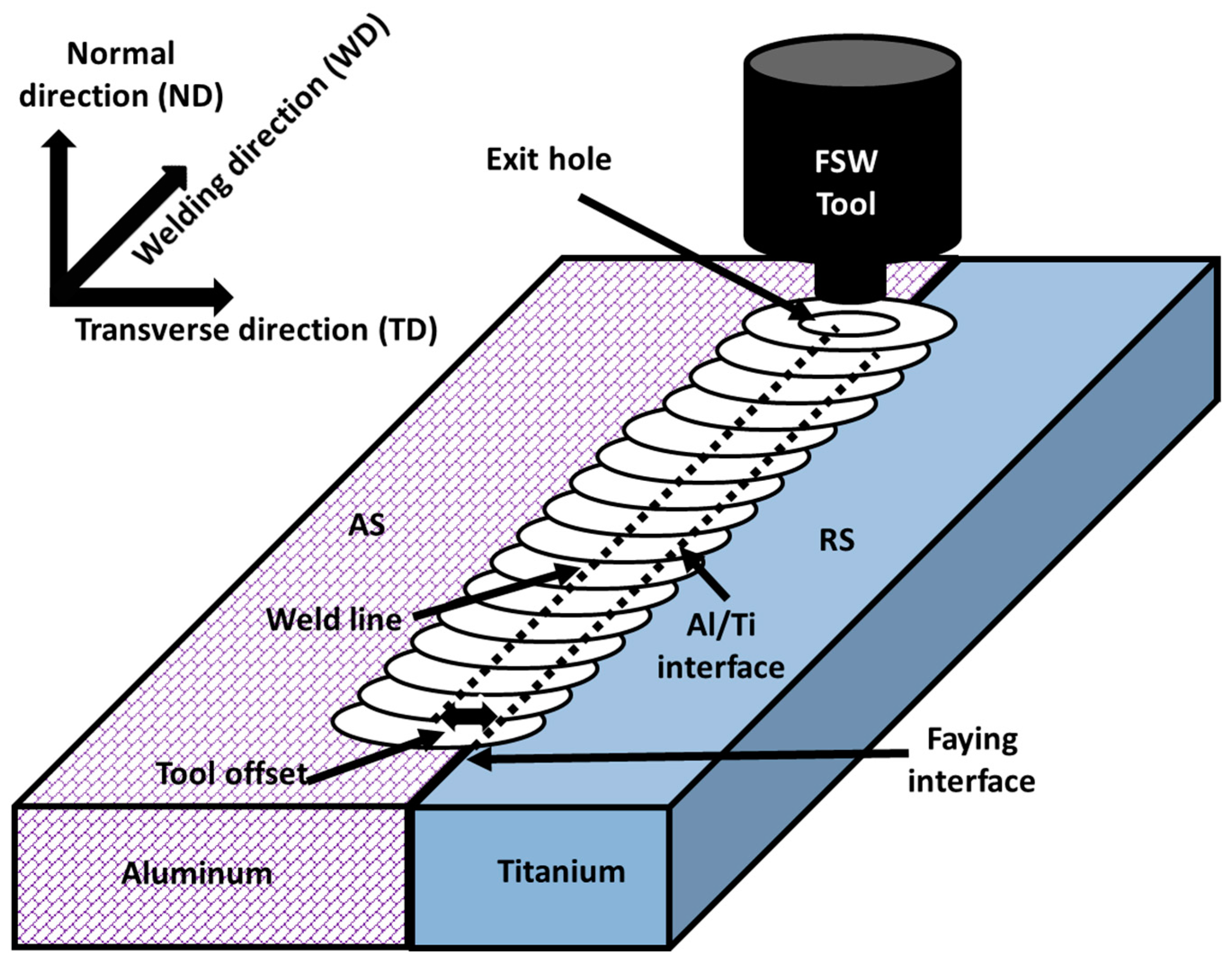
2.2. FSW and Optimization of Parameters

The rectangular plates of commercially pure (cp)-Al and cp-Ti are tightly clamped on the advancing side (AS) and retreating side (RS) of the tool on the machine bed, respectively. Experiments are carried out in a three-axis FSW machine that is in-house at the Indian Institute of Science (IISc), Bengaluru (India), and was developed jointly with ETA Technology Pvt. Ltd, Bengaluru (India). The tool is placed horizontally, and the plates are held in a vertical position, as schematically shown in Figure 1. This is a unique feature of the machine. The machine allows for the experimental parameters to be varied during an experiment, providing flexibility in the optimization of the FSW process. A custom-made cylindrical-shaped welding tool is made of tungsten carbide–cobalt (WC-8 wt% Co) alloy, with a shoulder diameter of 20 mm, pin diameter of 4.0 mm, and pin length of 3.5 mm.
In order to obtain a sound dissimilar weld of Al/Ti, the Taguchi method was adopted to optimize the process parameters. The Taguchi method is a statistical approach used to optimize the parameters of a process by identifying the optimal combination of parameters that results in the best quality outcome. The control factors in the FSW technique that were considered for optimization were the tool rotation speed (rpm), traverse speed (mm/min) and tool offset position (mm). These factors are known to play a vital role in determining heat input and material flow during the FSW process, and therefore influence the microstructural, mechanical and corrosion properties of the resulting joints. Three levels of values were selected for each of these control factors, as shown in Table 3. To examine the quality characteristics of the weld, an orthogonal array (OA) design was employed, and a total of nine experiments were conducted. The tool tilt angle was maintained at 2.5 degrees for all experiments. The relationship between the process parameters (control factors) and quality characteristics (tensile strength) of the weld were elucidated by evaluating the signal-to-noise (S/N) ratio for each experiment. The S/N ratio provides a measure of the quality of the weld for each experiment and is calculated based on the deviation from the target value of the tensile strength.

2.3. Microstructural and Phase Analyses

The welded plate was sliced to the desired dimensions, perpendicular to the welding direction (cross-section) using an electrical discharge machine (EDM) for microstructural investigations. The cross-sections of the welds were polished using silicon carbide (SiC) paper of grade 200–3000 grits and later, diamond-polished up to 0.05 microns. A detailed microstructural investigation of the optimized Al/Ti weld was performed using a scanning electron microscope (SEM) (FEI, Model Quanta-200, USA). In addition, the electron backscatter diffraction (EBSD) facility available in the same machine was utilized to understand the crystallographic orientation in the weld. It is to be noted here that prior to EBSD analysis, the samples were electro-polished for Al (Struers, Model Lectropol-5, Denmark). The phase analysis of the optimized Al/Ti weld was performed using an X-ray diffractometer (Rigaku, Model TTRAX III, Japan) with Cu Kα radiation, operated at a voltage of 40 kV and current of 20 mA.
X-ray computed tomography (XCT) was conducted using the Zeiss Versa 520 system, employing a rotating turntable for 3D non-destructive visualization of weld nuggets. In this X-ray computed tomography setup, the X-ray source produced a cone beam focused on the sample, forming a 2D grey-scale radiograph on the detector screen as it passed through or attenuated. Scan resolution depended on the magnification factor, determined by the relative positioning of the source (60 mm) and detector (70 mm) geometry. An additional 4× optical magnification covered the field of view during the scan, achieved through movable X-ray source and detector positioning. The sample, on a rotating turntable, aligned the weld zone with the field of view for perpendicular X-ray path axis and sample cross-section alignment. A resolution of 6 µm was achieved, depending on sample dimensions.
X-ray diffraction (XRD) was done in the range of 30–90° with a scanning rate of 2°/min and scanning step of 0.02°.

2.4. Mechanical Properties

A tensile test was conducted for evaluating the mechanical properties of the welds formed with the process parameters optimized using Taguchi’s method. The samples for the test were dissected perpendicular to the welding direction in accordance with the ASTM E8 standard using a wire EDM. Before testing, ~0.2 mm was chipped off from the top and bottom of the specimen in order to achieve a smooth surface and also to eliminate any surface effects. The thickness of the specimens used for tensile testing was in the range of 3.3 mm to 3.5 mm; this was used for calculating the tensile properties. The tensile test was performed at a strain rate of 10−3/s using a Bangalore integrated System Solutions universal testing machine (BiSS-UTM) at room temperature.

2.5. Corrosion Studies

The corrosion behavior of the optimized Al/Ti weld was studied using a potentiodynamic polarization test in the presence of 3.5 wt% sodium chloride (NaCl) solution, and the results were compared to the corrosion behavior of Al. Both tests were performed using a potentiostat/galvanostat (Solarton Analytical, Model 1287A, UK) with a standard three-electrode cell. A platinum plate was used as counter-electrode while the silver/silver chloride (Ag/AgCl) electrode acted as a reference electrode during the potentiodynamic polarization test. This test was carried out in the potential range of ±1.5 V at a 1 mV/s scan rate. This test yields polarization curves, also known as Tafel plots, which have two curves, namely the anodic and cathodic curves. The intercepts of the tangential line drawn on these curves gives the corrosion characteristics, such as the corrosion current (Icorr) and corrosion potential (Ecorr), for the optimized Al/Ti weld and cp-Al weld.

3. Results

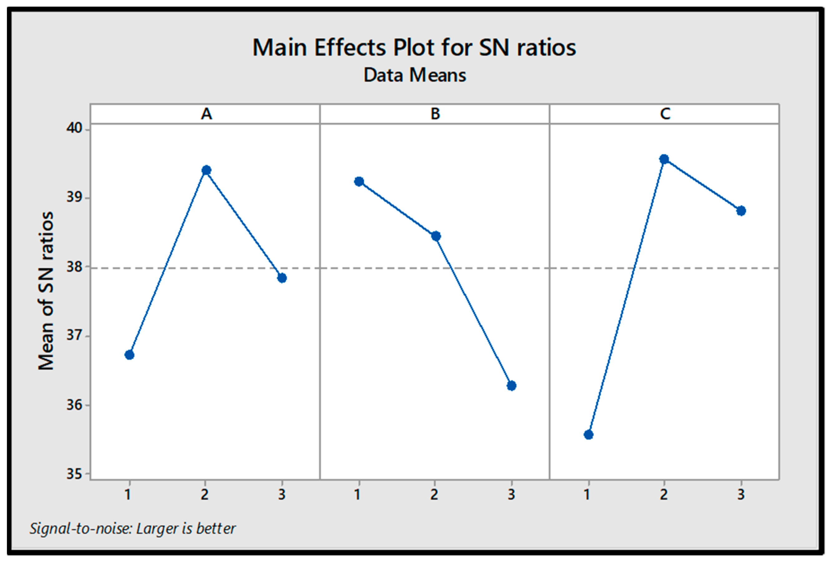
3.1. Process Parameter Optimization

The fabrication of the Al/Ti FSW joint involves complicated relations among the material flow, heat input and mechanical properties, which are predominantly governed by the process parameters. To understand these relationships and optimize the process parameters, OA design of the Taguchi experiment was conducted as shown in Table 3. However, in order to determine a specific process parameter that has commendable impact on the quality characteristics (tensile strength) of the weld, it is necessary to determine the S/N ratio. There are three categories of performance characteristics employed for analyzing the S/N ratio: 1. the lower–the better, 2. the higher–the better, and 3. the nominal–the better. In order to acquire the maximum tensile strength for Al/Ti welds, the category of ‘the higher–the better’ is utilized. Thus, the S/N ratio ηij for the ith experiment in the jth test is given by:
η i j = 10 l o g 10 1 n j = 1 n 1 y i j 2
where yij denotes the value of tensile strength in the ith experiment in the jth test and n represents the total number of tests. The tensile strengths of all the nine Al/Ti FSW joints were determined as mentioned in Section 2.4 and their values can be seen in Table 4, along with the S/N ratios calculated using Equation (1).
The average mean and S/N ratio for each control factor, namely, rpm (A), traverse speed (B), and tool offset position (C), were calculated for nine different experiments. The change in trend of both the average mean and S/N ratio for each control factor is given in Table 5 and plotted in Figure 2. It is observed that the average S/N ratio is directly proportional to the joint tensile strength. For example, as shown in Figure 2, the average S/N ratio initially increases and then decreases as the level of A (i.e., rpm) increases from level 1 to level 3. This indicates that the joint tensile strength initially increases and then decreases as the tool rotation speed increases from 600 to 1000 rpm. Therefore, the optimal level of tool rotation speed can be considered as 800 rpm. According to the results presented in Table 5 and Figure 2, it is possible to examine the effect of each control factor on the tensile strength of the welded joint at various levels. The rankings for maximum effectiveness were computed based on delta values, indicating the spread or difference between the highest and lowest average response values associated with each factor.
By analyzing the change in trend of the average mean and S/N ratio for each control factor, the optimal parameter combination for achieving a sound weld of Al and Ti was found to be A2B1C2, which corresponds to a tool rotation speed of 800 rpm, traverse speed of 100 mm/min and offset of 2 mm. This combination of parameters can lead to a significant improvement in the tensile strength of the welded joint and demonstrates the effectiveness of the Taguchi method in optimizing process parameters. Analyzing the delta value reveals that tool offset exerts the most significant influence, followed by traverse speed in second place, while tool rotation speed demonstrates relatively less impact on the tensile properties of the welds.

3.2. Macrostructural Features of the Optimized Weld

Figure 3 depicts the cross-sectional image of the optimized Al/Ti weld, in which the cp-Al and cp-Ti sides can be differentiated as grey and black regions, respectively. A continuous light grey-colored layer with an average thickness of 0.5 ± 0.5 µm can be noticed on top of the weld. This layer could be Al that might have become plasticized and squeezed out during welding as a result of temperature rise (~400–500 °C), as reported by Kar et al. [18]. In addition to this, Figure 2 shows a distinct light grey weld nugget region at the centre of the weld with flakes and fragments of Ti particles distributed throughout. Interestingly, there were no signs of volumetric defects such as pores, wormholes or cracks in the weld nugget region. However, a significant variation in the distribution pattern of Ti particles was detected. Fine Ti particles were distributed at the centre of the weld nugget while large flakes of Ti were spotted at the top and retracting sides. Such distribution of Ti particles in the Al matrix can be due to mechanical mixing on account of tool rotation and the associated stirring process [10]. Although the distribution of a few flakes and Ti fragments was visible in the macrograph, very fine particles were not clearly recognized. Kar et al. [18,19] have reported that the distribution of Ti particles and their size can influence the microstructural evolution and mechanical properties of Al/Ti welds. In order to have a detailed understanding about the distribution of Ti particles, X-ray computed tomography (XCT) analysis was performed in the weld nugget region [20].
The XCT images of the optimized sample corresponding to 2.0 mm tool offset are shown in Figure 4. These images represent the 2D view in the WD-TD planes and are observed from the ND plane, as depicted in Figure 1.
The blue color in the image represents titanium, and the image is a two-dimensional (2D) representation of a three-dimensional (3D) image. The distribution of Ti particles is the most noticeable feature, with particles of different sizes and shapes distributed inhomogeneously in the weld nugget. It is worth noting that the threshold range for Al was not selected; hence, it is not visible in the image. The distribution of Ti particles shows a variation in size and shape. The top view (Figure 4a) reveals that Ti particles with different sizes are distributed inhomogeneously in the weld nugget. To investigate the volume distribution of Ti particles further, particle size filters were used. Figure 4b–f display the filtered images corresponding to various volume ranges of particles. In the figures, the volume range used is mentioned at the top corner of each image. Very fine particles (volume less than 102 µm3 ≈ 6 µm in size) could not be captured due to a limitation in resolution of the equipment. The fine particles were homogeneously distributed (Figure 4b–c), whereas large particles exhibited scatter in their distribution within the weld nugget (Figure 4d–f). The coarse Ti particles and flakes seemed to be elongated in shape, as seen in Figure 4e–f.

3.3. Interfacial Characteristics of the Optimized Weld

A detailed microstructural examination of the nugget zone was carried out using SEM in the backscattered electron (BSE) mode to characterize the location of particles and quality of Al/Ti interfaces. This information is helpful in understanding the mechanism of Ti particle formation. Figure 5a shows a low-magnification micrograph of the weld nugget, illustrating Al/Ti interfaces and Ti particles (marked by arrows). In addition, the joining interface is also noticed. The wavy morphology of the joining interface is attributed to the severe deformation and associated fragmentation of Ti during welding. A magnified view of the Al/Ti joining interface is shown in Figure 5b. The figure clearly indicates the possible micro-fragmentation at the Ti interface. The cracks developed during the fragmentation of Ti have propagated into the Ti interface. The interaction of cracks has led to the formation of Ti particles that were distributed in the weld nugget [10]. Figure 5c shows a particle that has different compositions and morphologies on its two opposing sides. One side of the particle contains a number of fragmented interfaces; the fragmented zones chemically reacted with the Al matrix, which led to the formation of intercalated particles (Figure 5d). Such intercalation and chemical reaction of Ti with Al is expected to provide superior bonding and higher mechanical properties [11].
The local reaction at all the dissimilar interfaces (Ti particles/Al matrix, Al/Ti at the weld interface) is a prerequisite for superior dissimilar welds. The reaction across the interfaces can be enhanced with optimum mechanical mixing and inter-diffusion. The degree of reaction, through elemental composition, at the interfaces was characterized using energy dispersive spectroscopy (EDS) line scan analysis as shown in Figure 6. The scan results illustrated in Figure 6b showed the plausible formation of intermetallics such as Al3Ti and AlTi. Titanium trialuminide was expected to evolve in the severe mechanically mixed zone, whereas it was predicted that AlTi would form at the Al/Ti interface. Furthermore, it was observed that the thickness of the interlayer at the mechanically mixed zone, (MMZ = 15 µm; interface 2) is larger than that of the particle interface (4 µm; interface 1). Therefore, the result indicated that the mechanically mixed zone and intercalated particles are the potential zones for brittle Al3Ti formation, and hence, the evolution of intermetallic compounds can be controlled by engineering the mechanical mixing of elements during welding [6].

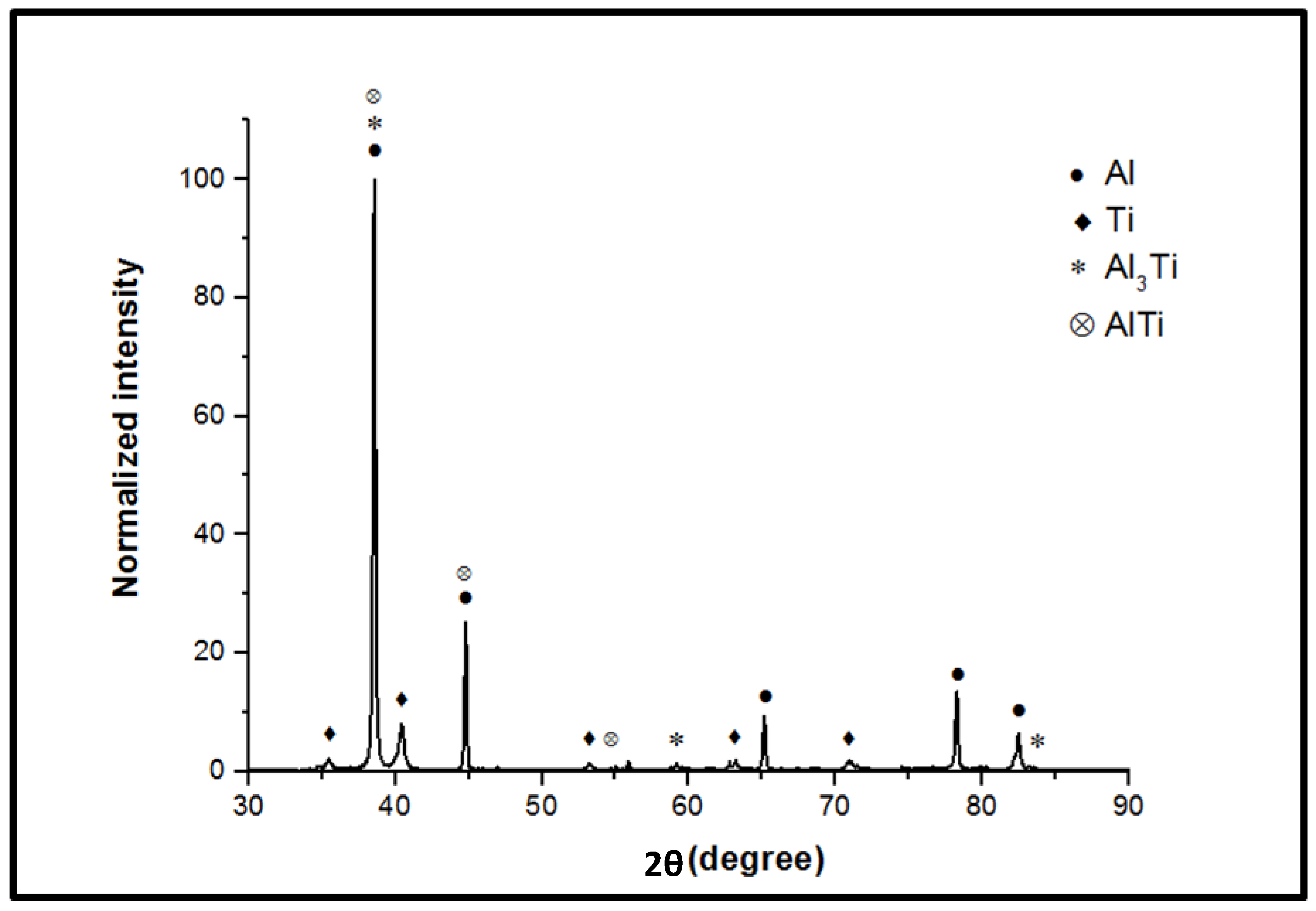
3.4. Phase Evolution in the Optimized Weld

The evolution of phases in the optimized Al/Ti weld can be understood by XRD analysis, which is shown in Figure 7. The diffraction pattern of the Al/Ti weld displayed major peaks at 38.46°, 44.71°, 65.09°, 78.22° and 82.42°, corresponding to the (111), (002), (022), (113) and (222) planes of cubic Al, respectively (according to the ICDD card no. 98-004-3423). In addition, peaks were seen at 35.08°, 40.17° and 53.02°, corresponding to the (010), (011) and (012) planes of hexagonal Ti, respectively. The formation of the Al3Ti phase was confirmed by the peaks seen at 47.2°, 58.6°, 64.9°, 69.01° and 74.65°, corresponding to the (020), (015), (024), (220) and (116) planes of tetragonal Al3Ti, respectively. The presence of the AlTi phase was confirmed by the peak at 40.6°, corresponding to the (200) plane of cubic AlTi. The AlTi phase was found to be present in smaller quantities compared to the Al3Ti phase. The formation of intermetallic phases in the weld is attributed to the diffusion of Al and Ti atoms at high temperature, along with the generation of a high amount of heat during FSW.

3.5. Microstructure Development in Al

The deformation of Al is a vital factor in dissimilar FSW because Al is deformed more than Ti due to shifting of the tool towards Al. To reveal the mechanism of grain formation, an EBSD examination of Al in the centre of the nugget zone was carried out; the maps constructed from the examination are shown in Figure 8. A confidence index (CI; image quality) cut-off of 0.2 was used to remove noise in the image; this noise is associated with Ti particles and other phases developed during welding. From the inverse pole figure (IPF) map, no preferential crystallographic orientation was observed in the microstructure. An equiaxed microstructure was witnessed throughout (Figure 8a). A substantial grain refinement, from 45 µm to 7 µm, was achieved due to severe plastic deformation during FSW. Figure 8b shows the grain boundary character distribution (GBCD) map of the same region. The GBCD divides grain boundaries into three types, as shown in the table in Figure 8b. The grain boundaries were demarcated by a specific range of orientation angle as shown in the attached table. A few grains consisting of a mixture of different types of boundary characters were noticed (marked with circles in Figure 8b). This indicated dynamic recovery (DRV) and the dislocation-assisted sub-grain rotation and coalescence mechanism of grain evolution, which are generally seen in the process of continuous dynamic recrystallization (CDRX). Figure 8c shows the grain orientation spread (GOS) map. In this map, the average orientation of each point within the grain was calculated and a value was assigned to the grain. Grains with different orientations and low GOS values were distributed throughout the matrix. Grains with low GOS values (0 < θ ≤ 2) were considered as recrystallized grains [10] and therefore, 65% of the grains were considered as dynamically recrystallized. These grains contained a very low fraction of kernel average misorientation (KAM) as shown in Figure 8d. In the KAM map, local difference in orientation was calculated based on KAM (first order neighbours) of the grain to which the point belonged. Therefore, a low KAM value indicates accumulation of a smaller number of dislocations and a strain-free grain.

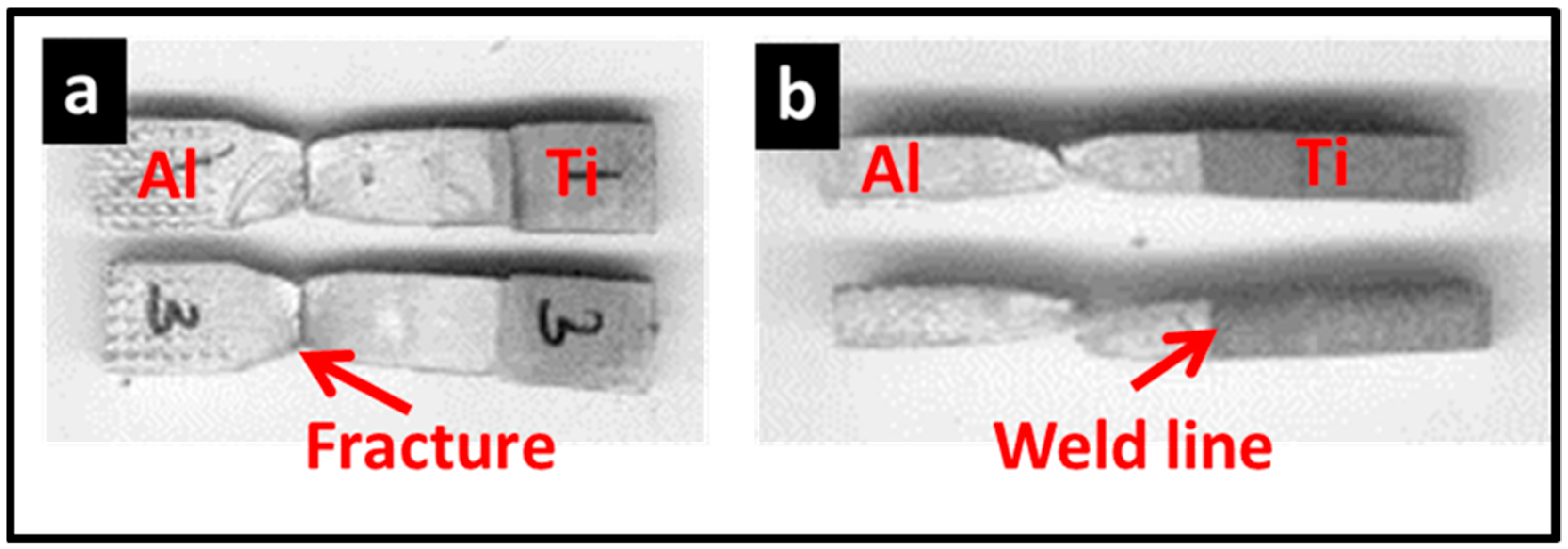
3.6. Tensile Properties of the Weld

The applicability of any structural component ultimately depends on the tensile properties of the weld. Hence, a tensile test of this weld was carried out and compared to one with base Al to comprehend the welding efficiency. The ultimate tensile strength (UTS) and ductility (percentage of engineering strain to fracture) of the weld are listed in Table 6. The UTS of this weld (131 MPa) was about 24% higher than that of base Al. The weld sample displayed 25% ductility, which was 10% higher when compared to base Al. After tensile testing, the position of the fracture and fracture surface of the samples were analyzed to find out the mechanism of fracture and detect the weakest zone in the weld. The observation revealed that the tensile samples failed at the interface between the stir zone and base material (RS of the weld) but not at the joint interface (Figure 9). The weakest location was the heat-affected zone (HAZ), and this is the common zone of weld failure. This clearly indicated a sound weld and good interfacial bond. In contrast, extensive neck formation (elongation) was observed on the tensile sample before fracture. The fracture surface of the tensile sample was examined under SEM (Figure 10). Fractography indicated a ductile mode of fracture. A multi-modal distribution of dimples with different morphologies and sizes was observed on the fracture surface (Figure 10a). In addition, a number of shear deformation marks were observed on the walls of the dimples. This indicated inhomogeneous deformation during tensile loading, which would occur due to variation in the microstructure across the weld, leading to multi-modal deformation [15]. This multi-modal deformation and dislocation interaction initiates cracks. Propagation of these cracks has resulted in void formation and final failure of the sample by the conventional ductile mode of fracture. This illustrates the important effect of gradient in microstructure on fracturing of the tensile sample. Since fracture occurred within the weld nugget or RS of the weld, the evolution of a refined microstructure has caused improved tensile properties of the weld. This is because the refined microstructure promotes the development of a large number of dislocation sources and deformation bands, which leads to the enhancement of the ductility of the material. The presence of fine particles and a homogenous distribution of the particles in the weld nugget can also contribute to the improvement of ductility. Additionally, the intercalated particles and recrystallized grains in the weld nugget can improve the tensile strength of the weld.

3.7. Corrosion Properties

The corrosion characteristics of the optimized Al/Ti joint and cp-Al were obtained from the Tafel plot shown in Figure 11, which was the result of performing a potentiodynamic polarization test in 3.5 wt% NaCl solution. The Tafel plots of both these samples exhibited an active region and a passive region in the potential range of −1.2 V and 0.7 V. The corrosion characteristics, namely, the corrosion current (Icorr) and corrosion potential (Ecorr), were captured from the Tafel plots and were found to be 1.143 × 10⁻⁶ A/cm2 (Icorr) and −0.44 V (Ecorr) for pure Al. On the other hand, the optimized Al/Ti weld showed Icorr and Ecorr values of 4.23 × 10⁻⁷ A/cm2 and −0.23 V, respectively. This clearly indicated that the Ecorr value of the optimized Al–Ti weld is ~47% higher than that of cp-Al.

4. Discussion

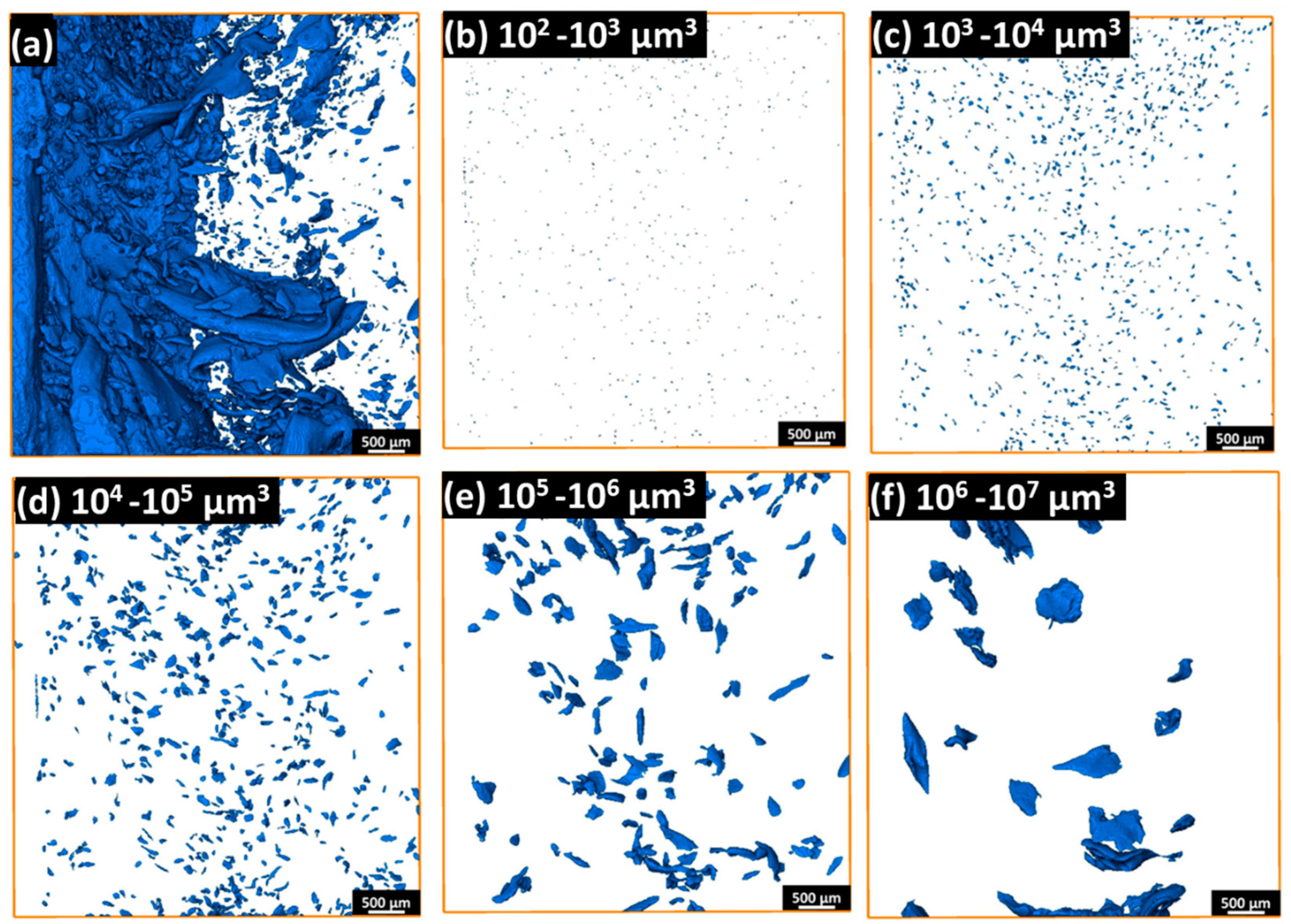
4.1. Mechanism of Particle Formation

In FSW, the interfacial friction and deformation process of the material affect the temperature rise and heat input in the processed material. The rise in temperature mostly depends on the physical and thermal properties of the material. For example, Kar et al. [10] showed the formation of a continuous Al-based coating on top of the weld nugget during two-pass friction stir welding of Al alloy to Ti alloy. The Al coating restricted interaction between the high-melting point material (Ti) and the rotating tool. Hence, it controlled the interfacial friction and final temperature rise of the weld, which was approximately 421°C. A similar temperature rise has been reported during similar and dissimilar FSW involving Al [18]. During deformation, the material rotates with the tool due to sticking friction conditions, and it is consolidated at the trailing edge/advancing side of the weld, leading to the formation of a joint. The strain and temperature experienced by the material are severe during this process. In some cases, the rise in temperature is insufficient for recrystallization of certain materials, such as titanium, and they are subjected to severe deformation under low temperatures and high strain rates. At such low temperatures and high strain rates, the formation of adiabatic shear bands (ASBs) is likely to occur [10]. ASBs induce sharp cracks at the interface, which lead to the formation of a mixture of fine particles (Figure 4b–c) and large flake-shaped particles (Figure 4e–f) during continuous rotation of the tool in welding. The evolution of ASBs is a local plastic instability process, and the corresponding fragmentation in titanium leads to the formation of particles with different morphologies and sizes, as seen in Figure 3 and Figure 4.

4.2. Recrystallization Mechanism in Al

It was observed that the microstructure of the weld contains a high fraction of particles in the Al matrix. During welding, the semisolid Al flows around these particles. The restriction, by these particles, to the conventional flow of Al leads to flow discontinuity, which develops a strain inhomogeneity across these particles. Hence, the required critical strain for recrystallization is easily reached and the Al matrix has regions of easy nucleation [21]. Qiao et al. [22] reported that the presence of hard particles (SiC) in the Al matrix increases the local strain in the matrix and causes lattice misorientation. The strain around the particles provides more nucleation sites for nucleation grains. These nuclei grow further at the welding temperature; however, the strain gradient around these particles remains constant during welding. This process continues during deformation and the microstructure of Al around the particles is subjected to continuous deformation and refinement. This leads to the evolution of a substantially refined microstructure around the particles compared to that of the microstructure of Al matrix. Similar results were also reported by Singh et al. [23] for the AA 5083 alloy subjected to friction stir processing (FSP). During post-weld cooling from the welding temperature, the nucleation of any strain-free grains occurs; the sweeping motion of grain boundaries that have high strain gradients leads to the formation of recrystallized grains. These grains are characterized by a smaller number of dislocations within the grain and very low GOS values. These grains are surrounded mostly by high-angle grain boundaries. An observation has been reported by Rhodes et al. during the simulation of the FSW condition using the tool plunge and extraction method followed by annealing [24]. Since Al has a high stacking fault energy (SFE), it is prone to DRV during thermo-mechanical processing. Progressive dislocation generation and annihilation through DRV results in the development of grain boundaries from low angle to high angle. A similar feature was observed in the grain boundaries (shown with mixed colors in Figure 8b), indicating the process of grain development. The combination of DRV, dislocation-assisted sub-grain rotation and coalescence during severe deformation at high strain rates and low temperatures is the micro-mechanism leading to CDRX [23]. In addition, the presence of grains with random grain orientations (Figure 8a), low GOS values (65%; Figure 8c) and absence of free dislocations also point to the recrystallized microstructure of Al. Such a microstructure can accommodate a higher plastic strain that that of the deformed microstructure and hence, the tensile sample exhibited a higher ductility.

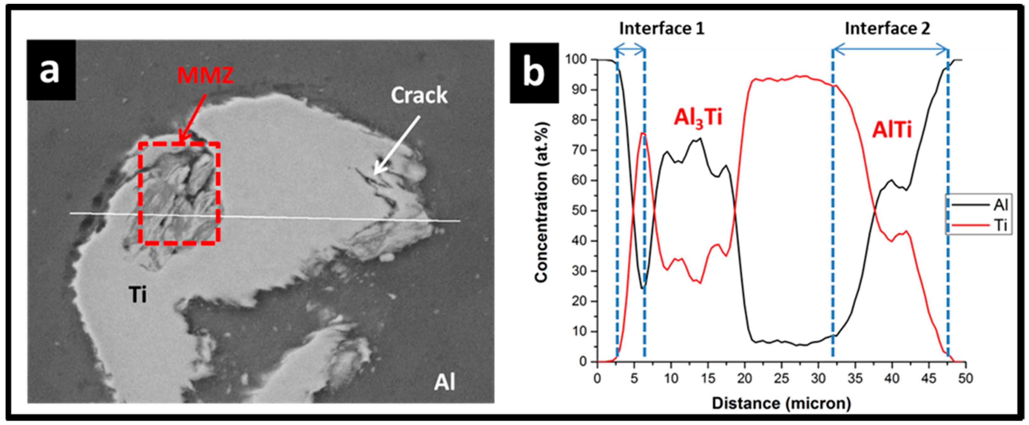
4.3. Mechanism of Phase Evolution

The mechanism of phase evolution in friction stir welding (FSW) involves several factors including process parameters, temperature, strain rate, residual stress and reaction kinetics. The temperature rise at the Al/Ti interface and the accumulation of residual stresses in the deformed Ti particles promote elemental diffusion [25,26], leading to the formation of intermetallic phases such as AlTi and Al3Ti [6,27]. The higher surface-to-volume ratio of fine Ti particles enhances the inter-diffusion of Al and Ti, leading to the formation of more intermetallics compared to large flakes. According to Gibb’s free energy diagram of TiAl and TiAl3, the formation of TiAl is thermodynamically unstable below 500°C; however, the formation of TiAl3 is possible [28]. Therefore, in most of the welds, the formation of AlTi intermetallics is restricted, and only possible by the enhanced kinetics of elemental diffusion during severe plastic deformation in the weld nugget. This condition occurs in the weld nugget due to the enhancement of surface energy of the Al/Ti reactive system and activation of reactant atoms by severe plastic deformation.

4.4. Improvement in Mechanical Properties of the Weld

The enhancement of mechanical properties, including tensile properties, are primarily attributed to the reduction of the brittle intermetallic phase (Al3Ti) in the weld, in addition to the most appropriate distribution of finer Ti particles as well as intermetallics. An enhanced mechanical bonding in the weld is anticipated due to interlocking of intercalated particles and elemental diffusion of fine Ti particles at the Al/Ti interfaces. The high surface-to-volume ratio of fine Ti particles enhances the interfacial reaction, giving rise to a sound weld. The distribution of fine particles during material mixing increases homogeneity in the microstructure of the nugget zone and therefore, inhomogeneity in the Al matrix reduces; this also contributes to a sound weld with a higher percentage of elongation before fracture of the tensile sample. Failure of the samples occurs primarily on the Al side of the weld. The Al in the weld nugget is substantially refined and recrystallized. The initiation of cracks and the initial phase of crack propagation can be delayed if the surface tensile residual stresses are low, which reduces the mean stress. The sub-grains with low-angle grain boundaries are possibly present in a work-hardened layer during fatigue testing, and crack nucleation can be retarded by such recrystallized microstructures. Generally, fine-grained materials exhibit superior crack initiation resistance compared to coarse-grained materials [29]. These factors result in an enhancement in mechanical properties, including an increase in ductility and resistance to crack initiation and propagation.

4.5. Improvement in Corrosion Properties of the Weld

On observing the mean values of Ecorr and Icorr for cp-Al and the optimized Al/Ti weld nugget region, it was seen that the optimized Al/Ti weld has a better corrosion resistance capability than cp-Al. It is to be noted from previous reports that the Ecorr value is independent of the weld zone; this means that the value remains unaltered despite a change in grain morphology. Vacchi and co-workers have attributed this phenomenon to the anodic and cathodic reaction rates that remain unaltered despite changes in the microstructure [16]. Considering this fact, the present study recorded Ecorr values only from the weld nugget region of the optimized Al/Ti. The significant enhancement in Ecorr value of the Al/Ti weld could be attributed to the large number of fine particles that are homogeneously distributed in the Al matrix, as seen in Figure 4b–c. These fine particles may have exhibited a cathodic behavior and formed a less intense galvanic cell with the matrix. This could have resulted in a low preferential dissolution of Al in the matrix. Also, a passive film could have formed around these fine particles, which further effectively resisted corrosion in the localized regions. On the other hand, upon considering the regions with higher particles sizes, the intensity of the galvanic cell could have been high; this could have caused a reduction in the effectiveness of the passive film, leading to greater dissolution of the matrix. This is in coherence with the postulates recommended by Bandil et. al. [30], wherein the dissolution of the matrix is said to be highly dependent on the size of the particles. Further, the results of the current study also concur with the report of Vacchi et al., who studied the corrosion behavior of friction stir spot welded AA6181-T4 and Ti-6Al-4V alloys [16].

5. Conclusions

In the present investigation, FSW of Al to Ti using Taguchi’s optimization technique has led to the development of a sound weld with enhanced mechanical and corrosion properties. A detailed examination of the microstructural features and evaluation of mechanical properties were carried out for the weld with optimally processed samples. Based on the above investigations, the following conclusions were made:
  • The Taguchi optimization method was used to determine the optimal FSW process parameters for welding commercially pure aluminum and titanium. The optimized parameters were a tool rotation speed of 800 rpm, welding speed of 75 mm/min, and tool offset of 2 mm.
  • Particle formation was due to the evolution of adiabatic shear bands and crack development, resulting in particles of different sizes. The morphology and size of the Ti particles mixed with Al varied, with fine particles being homogeneously distributed and larger particles and flakes being scattered and unpredictable.
  • A high fraction of recrystallized grains was noticed in Al due to deformation-induced recovery and continuous dynamic recrystallization. This is attributed to the higher SFE of Al and severe deformation at high strain and welding temperature. The evolution of strain-free grains in Al resulted in an enhancement in ductility of the weld.
  • The formation of intermetallic phases (Al3Ti and AlTi) was influenced by process dynamics, particle morphology, and weld temperature, with AlTi forming due to high stress-assisted deformation and thermal diffusion.
  • The enhanced mechanical properties of the weld are attributed to the defect-free weld interface, formation of intercalated particles, homogenous distribution of fine particles and recrystallization of Al matrix in the weld nugget.
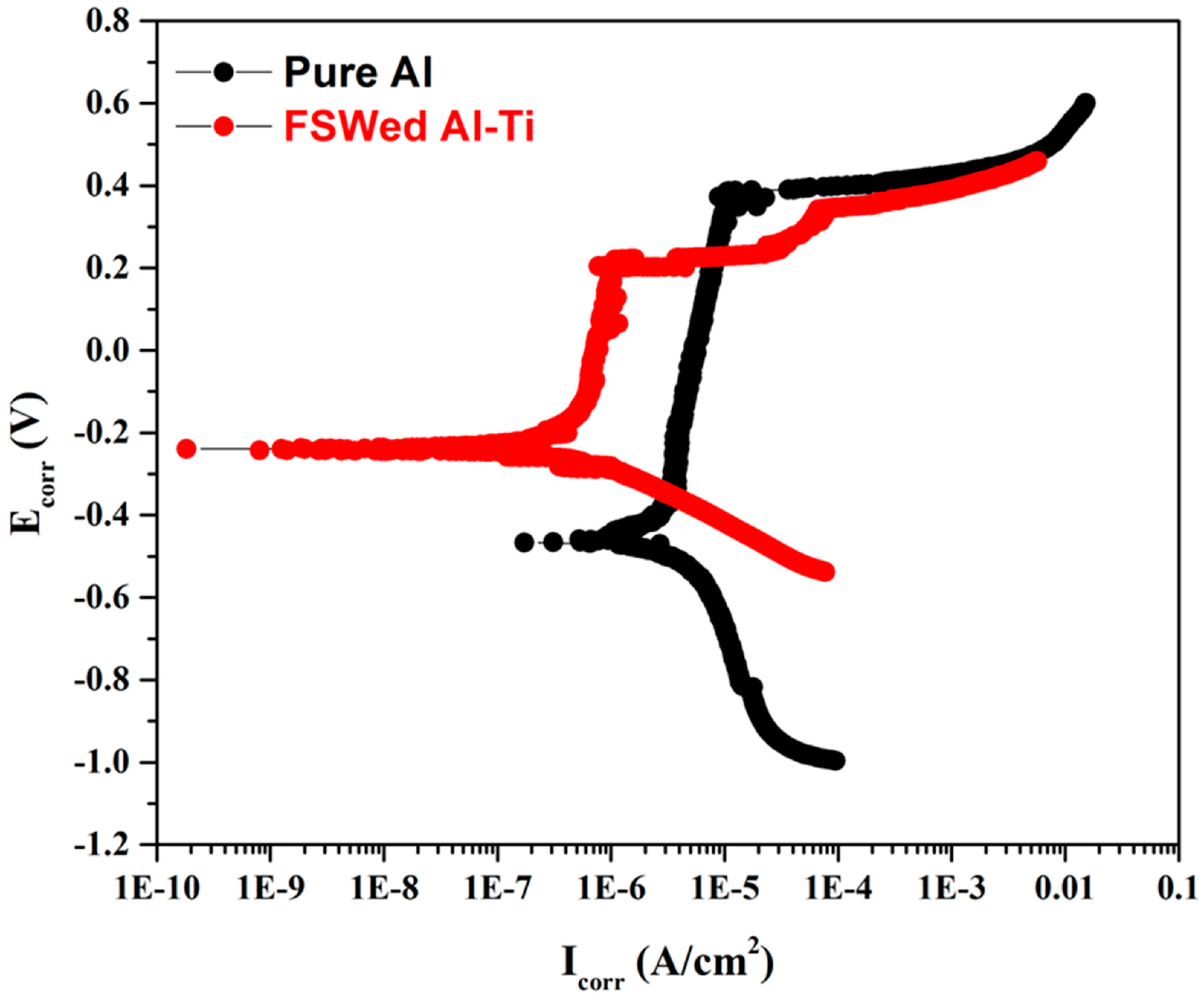
  • The fine particle distribution in the weld nugget area enhances corrosion resistance by displaying cathodic behavior, reducing Al dissolution. The optimized Al/Ti weld shows superior corrosion resistance compared to cp-Al, attributed to the significant enhancement in Ecorr value in the presence of homogeneously distributed fine particles. These particles form a less intense galvanic cell, limiting Al dissolution. Conversely, regions with larger particles exhibit higher galvanic cell intensity, diminishing the effectiveness of the passive film and increasing matrix dissolution.

Author Contributions

A.K.: conceptualization, methodology, validation, formal analysis, writing—original draft preparation, writing—review and editing; S.M. (Sribalaji Mathiyalagan): conceptualization, methodology, validation, writing—original draft preparation, writing—review and editing; S.S.: writing—review and editing, funding acquisition, supervision; S.V.K.: conceptualization, methodology, project administration, writing—review and editing, funding acquisition, supervision; S.M. (Sergey Malopheyev): methodology, funding acquisition; R.K.: methodology, funding acquisition. All authors have read and agreed to the published version of the manuscript.

Funding

This research was funded by the Department of Science & Technology (DST), grant number DSTO 1796.

Institutional Review Board Statement

Not applicable.

Informed Consent Statement

Not applicable.

Data Availability Statement

The data presented in this study are available on request.

Acknowledgments

The authors thank the Department of Science & Technology (DST), Government of India and Ministry of Education and Science (RMES) of the Russian Federation for funding (grant number DSTO 1796). They would also like to thank the Department of Mechanical Engineering and Advanced Facility for Microscopy and Microanalysis (AFMM) at the Indian Institute of Science, Bengaluru, India for providing experimental facilities.

Conflicts of Interest

The authors declare no conflicts of interest.

References

  1. Ohnuma, I.; Fujita, Y.; Mitsui, H.; Ishikawa, K.; Kainuma, R.; Ishida, K. Phase equilibria in the Ti–Al binary system. Acta Mater. 2000, 48, 3113–3123. [Google Scholar] [CrossRef]
  2. Casalino, G.; D’Ostuni, S.; Guglielmi, P.; Leo, P.; Mortello, M.; Palumbo, G.; Piccininni, A. Mechanical and microstructure analysis of AA6061 and Ti6Al4V fiber laser butt weld. Optik 2017, 148, 151–156. [Google Scholar] [CrossRef]
  3. Wang, P.; Chen, X.; Pan, Q.; Madigan, B.; Long, J. Laser welding dissimilar materials of aluminum to steel: An overview. Int. J. Adv. Manuf. Technol. 2016, 87, 3081–3090. [Google Scholar] [CrossRef]
  4. Leo, P.; D’Ostuni, S.; Casalino, G. Low temperature heat treatments of AA5754-Ti6Al4V dissimilar laser welds: Microstructure evolution and mechanical properties. Opt. Laser Technol. 2018, 100, 109–118. [Google Scholar] [CrossRef]
  5. Cross, C.E. On the Origin of Weld Solidification Cracking. In Hot Cracking Phenomena in Welds; Böllinghaus, T., Herold, H., Eds.; Springer: Berlin/Heidelberg, Germany, 2005; pp. 3–18. [Google Scholar]
  6. Kar, A.; Kailas, S.V.; Suwas, S. Formation sequence of intermetallics and kinetics of reaction layer growth during solid state reaction between titanium and aluminum. Materialia 2020, 11, 100702. [Google Scholar] [CrossRef]
  7. Li, Z.; Liu, Z.; Chen, D.; Mo, F.; Fu, Y.; Dai, Y.; Wu, X.; Cong, D. Study of Microstructure and Properties of Aluminum/Steel Inertia Radial Friction Welding. Metals 2022, 12, 2023. [Google Scholar] [CrossRef]
  8. Singh, V.P.; Patel, S.K.; Ranjan, A.; Kuriachen, B. Recent research progress in solid state friction-stir welding of aluminium–magnesium alloys: A critical review. J. Mater. Res. Technol. 2020, 9, 6217–6256. [Google Scholar] [CrossRef]
  9. Alam, M.M.; Jha, A.K.; Mukherjee, S.; Panda, S.; Chakraborty, S.S. A Review on Friction Stir Welding—A Green Manufacturing Technology. In Recent Trends in Manufacturing and Materials Towards Industry 4.0; Zahid, M.N.O., Sani, A.S.A., Yasin, M.R.M., Ismail, Z., Lah, N.A.C., Turan, F.M., Eds.; Springer: Singapore, 2021; pp. 869–880. [Google Scholar]
  10. Kar, A.; Suwas, S.; Kailas, S.V. Multi-Length Scale Characterization of Microstructure Evolution and Its Consequence on Mechanical Properties in Dissimilar Friction Stir Welding of Titanium to Aluminum. Metall. Mater. Trans. A 2019, 50, 5153–5173. [Google Scholar] [CrossRef]
  11. Ma, Z.; Sun, X.; Ji, S.; Wang, Y.; Yue, Y. Influences of ultrasonic on friction stir welding of Al/Ti dissimilar alloys under different welding conditions. Int. J. Adv. Manuf. Technol. 2021, 112, 2573–2582. [Google Scholar] [CrossRef]
  12. Pereira, V.F.; Fonseca, E.B.; Costa, A.M.S.; Bettini, J.; Lopes, E.S.N. Nanocrystalline structural layer acts as interfacial bond in Ti/Al dissimilar joints produced by friction stir welding in power control mode. Scr. Mater. 2020, 174, 80–86. [Google Scholar] [CrossRef]
  13. Choi, J.-W.; Liu, H.; Fujii, H. Dissimilar friction stir welding of pure Ti and pure Al. Mater. Sci. Eng. A 2018, 730, 168–176. [Google Scholar] [CrossRef]
  14. Wei, Y.; Li, J.; Xiong, J.; Huang, F.; Zhang, F.; Raza, S.H. Joining aluminum to titanium alloy by friction stir lap welding with cutting pin. Mater. Charact. 2012, 71, 1–5. [Google Scholar] [CrossRef]
  15. Kar, A.; Yadav, D.; Suwas, S.; Kailas, S.V. Role of plastic deformation mechanisms during the microstructural evolution and intermetallics formation in dissimilar friction stir weld. Mater. Charact. 2020, 164, 110371. [Google Scholar] [CrossRef]
  16. Vacchi, G.S.; Plaine, A.H.; Silva, R.; Sordi, V.L.; Suhuddin, U.F.H.; Alcântara, N.G.; Kuri, S.E.; Rovere, C.A.D. Effect of friction spot welding (FSpW) on the surface corrosion behavior of overlapping AA6181-T4/Ti-6Al-4V joints. Mater. Des. 2017, 131, 127–134. [Google Scholar] [CrossRef]
  17. Gharavi, F.; Matori, K.A.; Yunus, R.; Othman, N.K. Corrosion behavior of friction stir welded lap joints of AA6061-T6 aluminum alloy. Mater. Res. 2014, 17, 672–681. [Google Scholar] [CrossRef]
  18. Kar, A.; Suwas, S.; Kailas, S.V. Significance of tool offset and copper interlayer during friction stir welding of aluminum to titanium. Int. J. Adv. Manuf. Technol. 2018, 100, 435–443. [Google Scholar] [CrossRef]
  19. Kar, A.; Suwas, S.; Kailas, S.V. Two-pass friction stir welding of aluminum alloy to titanium alloy: A simultaneous improvement in mechanical properties. Mater. Sci. Eng. A 2018, 733, 199–210. [Google Scholar] [CrossRef]
  20. Mallmann, C.; Hannard, F.; Ferrié, E.; Simar, A.; Daudin, R.; Lhuissier, P.; Pacureanu, A.; Fivel, M. Unveiling the impact of the effective particles distribution on strengthening mechanisms: A multiscale characterization of Mg+Y2O3 nanocomposites. Mater. Sci. Eng. A 2019, 764, 138170. [Google Scholar] [CrossRef]
  21. Lauke, B. Effect of particle size distribution on fracture toughness of polymer composites considering plastic void growth after particle debonding. Mech. Res. Commun. 2015, 66, 1–6. [Google Scholar] [CrossRef]
  22. Qiao, Q.; Su, Y.; Li, Z.; Cui, Q.; Yu, H.; Ouyang, Q.; Zhang, D. Effect of overlapping region on double-sided friction stir welded joint of 120 mm ultra-thick SiCp/Al composite plates. Mater. Sci. Eng. A 2020, 782, 139238. [Google Scholar] [CrossRef]
  23. Singh, V.P.; Patel, S.K.; Kuriachen, B. Mechanical and microstructural properties evolutions of various alloys welded through cooling assisted friction-stir welding: A review. Intermetallics 2021, 133, 107122. [Google Scholar] [CrossRef]
  24. Rhodes, C.G.; Mahoney, M.W.; Bingel, W.H.; Spurling, R.A.; Bampton, C.C. Effects of friction stir welding on microstructure of 7075 aluminum. Scripta Mater. 1997, 36, 69–75. [Google Scholar] [CrossRef]
  25. Kar, A.; Kailas, S.V.; Suwas, S. Friction stir welding of aluminum to titanium: Quest for optimum tool-offset, deformation of titanium, and mechanism of joint formation. Int. J. Adv. Manuf. Technol. 2023, 128, 1943–1956. [Google Scholar] [CrossRef]
  26. Kar, A.; Kailas, S.V.; Suwas, S. Mechanism of variation in high-temperature grain stability of aluminum in dissimilar friction stir welds. Mater. Perform. Character. 2020, 6, 20190011. [Google Scholar] [CrossRef]
  27. Tian, S.; Liu, Y.; Ma, Q.; Zhang, P.; Zhou, J.; Xue, F.; Sun, Z. Intermetallics-induced directional growth of Sn whiskers in Sn-3.5Ag coating on Al substrate. Appl. Surf. Sci. 2021, 539, 148135. [Google Scholar] [CrossRef]
  28. Liu, Z.; Han, Q.; Li, J. Fabrication of in situ Al3Ti/Al composites by using ultrasound assisted direct reaction between solid Ti powders and liquid Al. Powder Technol. 2013, 247, 55–59. [Google Scholar] [CrossRef]
  29. Ghosh, S.; Bibhanshu, N.; Suwas, S.; Chatterjee, K. Surface mechanical attrition treatment of additively manufactured 316L stainless steel yields gradient nanostructure with superior strength and ductility. Mater. Sci. Eng. A 2021, 820, 141540. [Google Scholar] [CrossRef]
  30. Bandil, K.; Vashisth, H.; Kumar, S.; Verma, L.; Jamwal, A.; Kumar, D.; Singh, N.; Sadasivuni, K.K.; Gupta, P. Microstructural, mechanical and corrosion behaviour of Al–Si alloy reinforced with SiC metal matrix composite. J. Compos. Mater. 2019, 53, 4215–4223. [Google Scholar] [CrossRef]
Figure 1. Schematic illustration of experimental plan with orientation of plates and welding zone. AS = advancing side and RS = retreating side.
Crystals 14 00305 g001
Figure 2. Main effects plot for mean of S/N ratio for tensile strength results.
Crystals 14 00305 g002
Figure 3. Cross-sectional macrostructure of the optimized Al/Ti joint showing the formation of small Ti flakes in the weld nugget region and continuous formation of Al on the top surface.
Crystals 14 00305 g003
Figure 4. (a) XCT-generated and reconstructed images of distribution of Ti particles in different volume ranges showing from WD-TD plans: (b) 102–103 µm3, (c) 103–104 µm3, (d) 104–105 µm3, (e) 105–106 µm3 and (f) 106–107 µm3. Segregation of particles reveals homogeneous and heterogeneous distributions of finer and coarser particles, respectively.
Crystals 14 00305 g004
Figure 5. (a) Low-magnification scanning electron micrographs of the weld, (b) fragmentation of Ti at the interface, (c) different morphologies of particles and (d) higher magnification image indicating deformation, fragmentation and reaction of Al and Ti.
Crystals 14 00305 g005
Figure 6. (a,b) EDS line scan analysis of an intercalated particle at the nugget zone exhibiting elemental mixing (atomic %) and possible phase evolution within the particle due to mechanical mixing and corresponding thermal diffusion. The results illustrate different elemental gradients and interlayer thicknesses.
Crystals 14 00305 g006
Figure 7. X-ray diffraction patterns for the samples, showing the evolution of intermetallic phases Al3Ti and AlTi.
Crystals 14 00305 g007
Figure 8. EBSD-generated map of Al adjacent to the weld interface showing (a) IPF + grain boundary map,(b) GBCD map, (c) GOS + grain boundary map and (d) KAM map with an appropriate color code corresponding to Al/Ti FSW.
Crystals 14 00305 g008
Figure 9. Photographic view of the tensile fracture samples from (a) top and (b) front side of the weld. The tensile samples failed on the RS, but within the weld nugget and not at the joint interface.
Crystals 14 00305 g009
Figure 10. Fractography of the tensile sample corresponding to 2.0 mm tool offset: (a) Low-magnification fractograph showing the multi-modal distribution of dimples (ductile mode of fracture) and (b) variation in the deformation morphology on the wall of the dimples, indicating inhomogeneous deformation during tensile testing.
Crystals 14 00305 g010
Figure 11. Tafel plots obtained from the potentiodynamic polarization test of cp-Al and optimized Al/Ti weld in 3.5 wt% NaCl solution.
Crystals 14 00305 g011
Table 1. Chemical composition of starting materials (mass fraction, %).
ElementCuMgSiFeMnTiZnCAlOther
Al0.0020.0030.170.120.0020.0090.003-99.660.03
Ti---0.30-99.51-0.08-0.11
Table 2. Mechanical properties of starting materials.
MaterialUltimate Tensile Strength (UTS), MPaDuctility, %
Al10418
Ti34420
Table 3. Taguchi design of experiments conducted for optimization of processing parameters.
LevelControl Factors
A
Tool Rotation Speed
(rpm)
B
Traverse Speed (mm/min)
C
Tool Offset Position (mm)
1600751.5
28001002
310001252.5
Table 4. Taguchi’s design of experiments showing the control factors, mean tensile strength and S/N ratio.
Exp. No.Control FactorsMean Tensile Strength (MPa)S/N Ratio
ABC
1600751.56736.739
260010025037.492
36001252.55635.928
48007528742.321
58001002.57941.877
68001251.54134.021
71000752.55838.661
810001001.55235.965
9100012525738.906
Table 5. Response of S/N ratios for the three control factors.
LevelsS/N Ratio
ABC
136.7239.2435.58
239.4138.4439.57
337.8436.2938.82
Delta2.692.953.99
Rank321
Table 6. Tensile test results of as-received Al and optimized Al/Ti weld.
MaterialYield Strength (MPa)Ultimate Tensile Strength (MPa)Elongation (%)
Optimized weld87.2413121
cp-Al71.5210619
Disclaimer/Publisher’s Note: The statements, opinions and data contained in all publications are solely those of the individual author(s) and contributor(s) and not of MDPI and/or the editor(s). MDPI and/or the editor(s) disclaim responsibility for any injury to people or property resulting from any ideas, methods, instructions or products referred to in the content.

