Article

Local Stress States and Microstructural Damage Response Associated with Deformation Twins in Hexagonal Close Packed Metals

1
Department of Applied Physics, Zernike Institute for Advanced Materials and Materials Innovation Institute, University of Groningen, 9747AG Groningen, The Netherlands
2
Department of Mechanical Engineering, Cape Peninsula University of Technology, Cape Town 7535, South Africa
*
Authors to whom correspondence should be addressed.
Submission received: 17 November 2017 / Revised: 13 December 2017 / Accepted: 18 December 2017 / Published: 21 December 2017
(This article belongs to the Special Issue Crystal Indentation Hardness)

Abstract

:
The current work implements a correlative microscopy method utilizing electron back scatter diffraction, focused ion beam and digital image correlation to accurately determine spatially resolved stress profiles in the vicinity of grain/twin boundaries and tensile deformation twin tips in commercially pure titanium. Measured local stress gradients were in good agreement with local misorientation values. The role of dislocation-boundary interactions on the buildup of local stress gradients is elucidated. Stress gradients across the twin-parent interface were compressive in nature with a maximum stress magnitude at the twin boundary. Stress profiles near certain grain boundaries initially display a local stress minimum, followed by a typically observed “one over square root of distance” variation, as was first postulated by Eshelby, Frank and Nabarro. The observed trends allude to local stress relaxation mechanisms very close to the grain boundaries. Stress states in front of twin tips showed tensile stress gradients, whereas the stress state inside the twin underwent a sign reversal. The findings highlight the important role of deformation twins and their corresponding interaction with grain boundaries on damage nucleation in metals.

Graphical Abstract

1. Introduction

The mechanical behavior of metals, is to a large extent, influenced by the changes in intrinsic length scales and the interaction between different microstructural features associated with them. A microstructure can be essentially defined as the overall arrangement of crystallites/grains and material defects (point defects, dislocations and grain/twin boundaries). Depending upon the volume of the probed region these features can considerably vary both topologically as well as dimensionally. Since the local stress state in a material is directly proportional to the density and spatial configuration of defects, this also means that internal/residual stresses can strongly vary across different length scales i.e., macro-, meso- and microscopic dimensions.

2. Background

Plastic deformation in metals is primarily carried out by the creation and motion of linear defects viz. dislocations. In polycrystalline materials with diverse grain orientations, the interfaces between differing crystallite orientations can present themselves as severe obstacles to dislocation motion. The resultant interaction between line defects and such grain boundaries often gives rise to complex geometrical configurations of stored dislocations that are associated with long-range elastic stress fields. These stored dislocations are termed as geometrically necessary dislocations (GNDs), since they ensure the geometrical compatibility of deformed grains across the grain boundaries. Superposition of such stress fields invariably results in a strong spatial heterogeneity in local stress states. Needless to say, the variation in local GND density levels directly influences the distribution of microscopic residual stresses in the grain and grain boundaries. Internal stresses are also influenced by mutual interaction of line defects leading to local entanglements of dislocations i.e., forest dislocations or statistically stored dislocations (SSDs), but their numeric contribution in comparison with GNDs progressively diminishes with increasing applied strains due to saturation in dislocation densities of the former for strains above ~0.1–0.2 [1]. On the other hand, GND dislocation associated with grain boundaries continue to increase linearly with applied shear strain [1], thus acting as the primary contributors to strain hardening. Such correlation between GND density levels and local stress gradients has been utilized in the past to explain local hardening phenomenon due to dislocation pile-up at grain boundaries. Eshelby et al. [2] showed analytically that a dislocation pile-up ahead of an insurmountable obstacle such as a grain boundary would result in a stress gradient that varies as “one over the square root” of the distance from the obstacle. In fact, the stress field in front of the spearhead of the dislocation pile-up resembles the stress field of a crack singularity in a linear elastic medium. Subsequent experimental observations by Hall [3,4] and Petch [5] independently re-established such a behavior in metals as the well-known Hall-Petch effect, wherein the mechanical strength of the material increases with a decreasing intrinsic length scale of the grain size.
The dislocation configuration near a grain boundary strongly determines the degree of pile-up and corresponding local stress concentration. Depending on the crystallography of the grain boundary certain slip/twin systems may find conjugate systems in the neighboring grain that facilitate complete or partial strain transfer. It must be mentioned here that like slip deformation, twins are described by their twinning plane and the direction of shear. A theoretical estimate of the feasibility of slip/twin transmission can be captured by the strain transfer parameter [6,7], expressed as,
m = ( n 1 · n 2 ) · ( b 1 · b 2 ) ,
where n1 and n2 are the normalized intersection lines common to the slip/twinning planes and the boundary plane, and b1 and b2 are the normalized slip/twinning shear directions in the pile-up and emission grains. The value of m provides a measure of the probability for possible transmissivity of a slip or twinning dislocation across the grain boundary. Maximization of strain transfer parameter m abates dislocation pile-up and promotes easier strain transfer across the grain boundary.
Precise measurement of residual stresses at different length scales is extremely vital in order to acquire a fundamental understanding of damage mechanisms in present day structural materials. Despite the availability of diverse techniques for estimating internal stresses such as, using hard X-rays, hole drilling, contour method, slitting and ring coring, very few methodologies allow estimation of stresses up to micron and sub-micron scale resolution. Diffraction techniques utilizing convergent beam or nano-beam, hard X-rays from synchrotron are some of the available methods that can resolve stress at inter/intra-granular level [8], but the availability of such facilities are scarce [9]. Lately, the measurement of local scale stresses can be performed by high resolution electron back scatter diffraction (HR-EBSD) wherein Kikuchi patterns from reference (un-deformed) and deformed states are used to measure the residual displacements, and subsequently calculate the local elastic strain and stress state [10,11,12,13,14]. However, the method is limited to 2-dimensional investigations wherein only subsurface information is obtained [8]. With the advent of dual-beam focused ion beam (FIB) field emission gun microscopes, measurement of residual stresses with simultaneous sub-micron lateral and depth resolution in a semi-automated and robust way [9] is made possible. In this way both the subsurface and bulk deformation contribution on internal stress build up is accounted for during stress quantification. The methodology utilizes correlative imaging and milling to remove material and estimate the local stress relaxation in the neighborhood. Depending upon the milling geometry, either multiple stress components of the whole stress tensor can be determined or spatial stress gradients along one stress component is evaluated. Digital image correlation (DIC) is utilized to determine relaxation induced displacements in the vicinity of the milled region.
In previous studies [15,16] the authors introduced a site-specific technique utilizing electron back scattered diffraction (EBSD) and FIB-DIC linear slit milling to accurately determine spatially resolved stress profiles in the vicinity of grain boundaries in commercially pure titanium. The investigations in the vicinity of different grain boundaries in commercially pure titanium revealed the appearance of a local stress minimum just next to the boundary. This was followed by a Hall-Petch type monotonic stress decrement to a steady state regime. Correlations with the GND density and local misorientation data further validated the observed trends (c.f. Figure 1a,b). The results further showed that the width over which the stresses relaxed in the vicinity of the boundary was strongly dependent upon the obstacle strength of the grain boundary i.e., the Hall-Petch coefficient, k H P (c.f. Figure 1c). The observed stress drop was justified by a local change in elastic stress fields arising from dislocation-dislocation and dislocation-grain boundary interactions that may lead to a relative depletion of dislocation densities in the vicinity of specific grain boundaries. It was shown that the stress fields due to dislocation-grain boundary interactions are long range in nature and can be of the order of 10 3   G even at distances 10 4 · b d (where, G is the shear modulus and b d is the Burgers vector for active dislocation slip) from the grain boundary plane.
Hexagonal crystal’ structures, due to their low symmetry, often exhibit anisotropic deformation behavior unlike face centered cubic metals with cubic symmetry. This typically arises from a lack of easily available slip deformation modes along the c-axis and the role of mechanical twinning in accommodating strain out of the basal plane [17,18,19,20]. Due to its inherent nature, deformation twinning strongly impacts crystallographic texture evolution as well as the grain scale stress evolution [21,22]. While plastic slip is spatially more homogeneous and lattice strain evolution is gradual, the onset of twinning involves sudden reorientation of a part of the crystal associated with significant lattice strain and localized shear. The localized lattice rotation during twinning leads to the creation of twin boundaries. These newly formed boundaries can dynamically refine the grain size and lead to significant latent hardening inside the twins on subsequent straining [23,24]. Furthermore, dislocations, grain-boundaries and twins can mutually interact. Such complex local plastic response often gives rise to significant stress heterogeneities in the vicinity of twins. The significance of understanding such localized stress fields is in determining their associated effects either on accommodating deformation close to crack tips or on nucleation and propagation of cracks and thus their tendency to limit ductility [21,22]. Unfortunately, due to the sudden nature of twin formation that comprises nucleation and propagation, capturing load partitioning between the twin and untwinned parent experimentally is still extremely important.
The current work therefore aims to extends the aforementioned combination of EBSD and FIB-DIC methodology to quantify stress fields arising from the interaction of twin boundaries with parent grains and grain boundaries in commercially pure titanium. The observed trends are subsequently discussed with respect to underlying physical processes and the subsequent impact of deformation twinning on fracture behavior of titanium is acknowledged.

3. Experimental Methods

Commercially available grade II titanium was subjected to room temperature in situ four-point bending test inside a Tescan Lyra dual beam (FEG-SEM/FIB) scanning electron microscope (Brno, Czech Republic). The initial microstructure comprised of coarse grains with a mean grain size of ~100 μ m . Prior to mechanical testing, bending specimens were prepared for EBSD measurements using conventional metallographic techniques [25]. Specimens were strained to a final surface true strain, ε   =   0.18 . Microstructural characterization was performed by means of EBSD, thereby extracting both topographical and orientation information about the individual grains. A step size of 0.3 μ m and hexagonal type of grid was used for the measurements. The acquired raw EBSD data was subsequently analyzed using EDAX-TSL OIMTM Analysis 7.3 (software and MTEX open source Matlab toolbox [26]. Slip traces in individual grains were imaged using in situ scanning electron microscopy (SEM) (Tescan Lyra, Brno, Czech Republic). The orientation of the grain boundary plane was determined by milling into the region containing the boundary using focused ion beam and examining the grain boundary trace along the milled cross section. All observations were made on the tensile surface of the bent specimen, with the direction of viewing parallel to the surface normal, hereinafter referred to as the A3 sample axis.

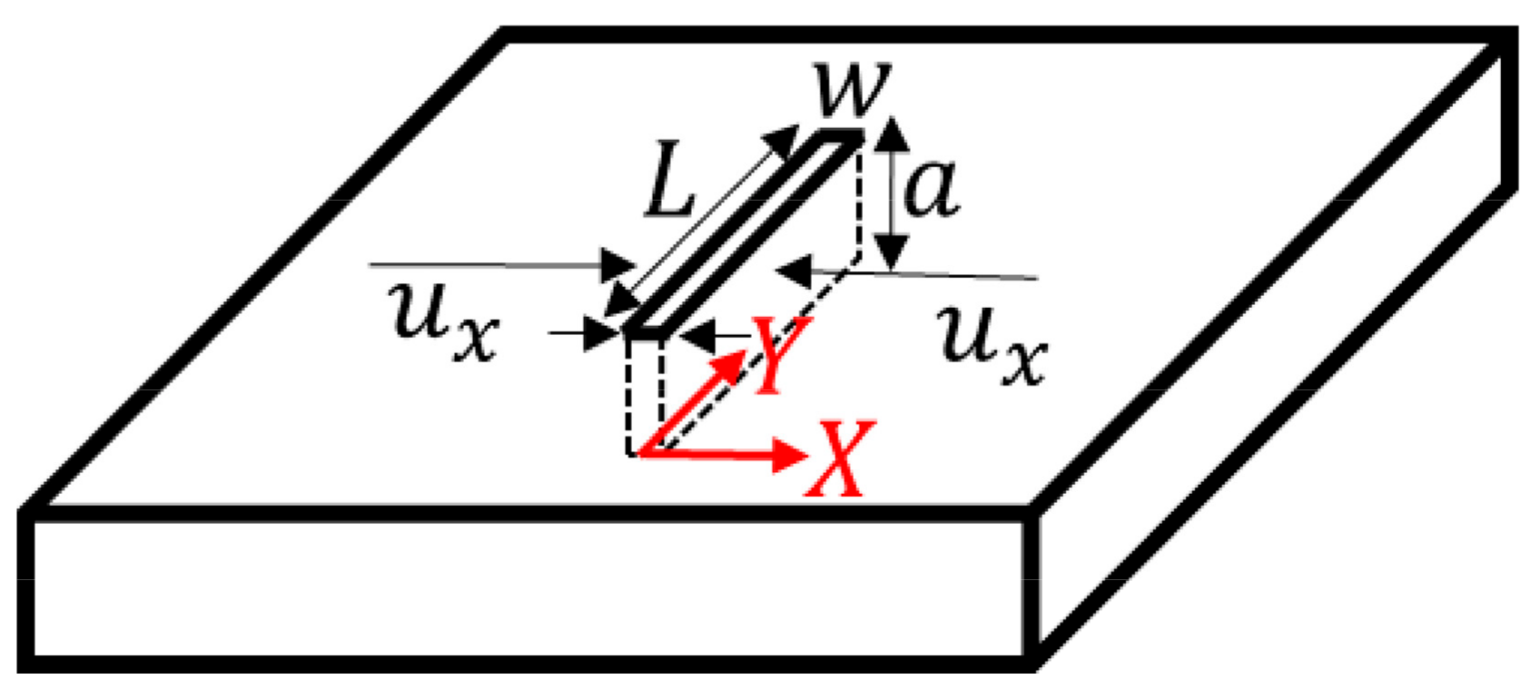
Residual Stress Measurement by FIB-DIC Slit Milling

The protocol followed during the measurement of residual stress starts with the acquisition of a scanning electron microscopy (SEM) image of the area to be analyzed. After recording the first image, a slit is milled on the surface. Then, a second image of the same area is taken. From the comparison of these two SEM images recorded before and after stress release by DIC the displacements are obtained. These displacements are compared with those obtained by the analytical solution for an isotropic elastic material, and the value of residual stress is obtained from the slope of the fitting [27].
Figure 2 shows the geometry of the slit used in our experiments including its dimensions: a length L , a width w and a depth a . The evaluated displacements of the surface, u x , are normal to the plane of the slit. The origin of coordinates is placed at the center of the slit. Considering the geometry, in plane displacements   U d i r can be related to residual stress σ d i r in the same direction by an analytical expression (see Equation (2)) such that [27,28,29]:
U d i r = 2.243 E σ d i r 0 a c o s θ ( 1 +   s i n 2 θ 2 ( 1 ν ) ) × ( 1.12 + 0.18 · sech ( t a n θ ) ) d z ,
where E is E / ( 1   ν 2 ) , E is the Young’s modulus, ν is the Poisson’s ratio, θ is a r c t a n ( d / a ) , a is the depth of the slit and d is the distance from the slit; d i r represents x or y directions. The displacements caused by the stress release depend on the slit depth a and are directly proportional to the σ / E ratio. Moreover, the extraction of the residual stress requires the a priori knowledge of the elastic properties of the material under study (i.e., Young’s modulus and Poisson’s ratio). In the present study, the adopted rectangular slit geometry allows measurement of only one stress component that is aligned laterally to the longitudinal direction of the slit.
SEM images acquired before and after FIB milling are processed using a commercial digital image correlation software GOM Correlate v. 2016 and subsequent displacements lateral to the slit are recorded for each facet (group of pixels) position.
Figure 3 shows an example of a typically obtained DIC contour map of relative displacements normal to the slit corresponding to the local stress release due to milling. The scale bar of the image is in the range of tens of nanometers. Each color means that a group of pixels is displaced over the respective number of nanometers. When studying the displacements normal to the plane of the slit, the displacement is to the right (red color) or to the left (blue). Consequently, data arrays comprising of facet ID, coordinates and relative displacements are exported for post processing and residual stress determination. A Matlab based script is utilized to empirically determine the residual stress values from the experimentally measured displacements, as per Equation (2).
In the current work, linear slits, oriented normal to the grain/twin boundary trace, with widths between 0.3–0.5 μ m , depths from 1.5–2.5 μ m , and lengths varying from 15–25 μ m (depending on the twin/grain size), were milled inside individual grains/twins showing pile-up, classified on the basis of measured local lattice misorientation values near the grain/twin boundary. For each slit, multiple SEM images of resolution 768 × 768 pixels were acquired at high magnifications (field of view of 10–15 μ m ) to ensure a high spatial resolution of measured displacement field. In order to obtain statistically sufficient data points, DIC was performed using a facet size of 19 × 19 pixels with a step width of 16 pixels. Yttria-stabilized Zirconia (YSZ) nano-particles were used for surface decoration to obtain optimum image contrast for high accuracy DIC analysis.
To quantify displacements in the range of nanometers, the precision of measurements at reduced length scales at high magnifications is critical. The accuracy of the measured displacement field from DIC, u x , y depends upon the image pixel size along x and y directions, N x , y and sub-pixel shift resolution parameter k , given by the expression [28,30]:
u x , y = k · ( N x , y ) .
Under favorable imaging conditions the value of k achievable from the DIC algorithm is 0.01, which amounts to a precision of 1 × 10 5 [30,31]. It must be mentioned here that the sub-pixel shift resolution is a major criterion for stress measurement with high spatial resolution. Due to the characteristics of the above expression, the measurement accuracy can be progressively improved with smaller imaging sizes i.e., view fields. In realistic cases, including imaging related drift inaccuracies, the sub-pixel shift resolution varies from 0.01 to 0.1. For instance, in the current work the pixel sizes range between 13–18 nm (for the above defined view fields and image resolution) leading to the resultant sensitivity of the DIC software of each measured displacement being in the range of 0.1 nm to 1.8 nm. In the present work, SEM imaging parameters were optimized as per ref. [30] to minimize experimental drift related inaccuracies.
Stress distributions at sub-microscopic length scales need not always be homogeneous i.e., constant stress all throughout the material, but may considerably vary spatially. In such cases, stress determination by simplistic averaging of all displacements along the slit length, misrepresents the actual stress state of the material. A multiple fitting approach [15,29], wherein a stress value is obtained for displacements corresponding to each row was implemented to account for spatially heterogeneous stress states. All stress calculations were made using orientation dependent elastic modulus values, extracted from ref. [32], wherein the angle between the indentation loading axis and the crystal c-axis was varied to obtain an angular dependence of the elastic modulus with respect to c-axis orientation.

4. Results and Discussion

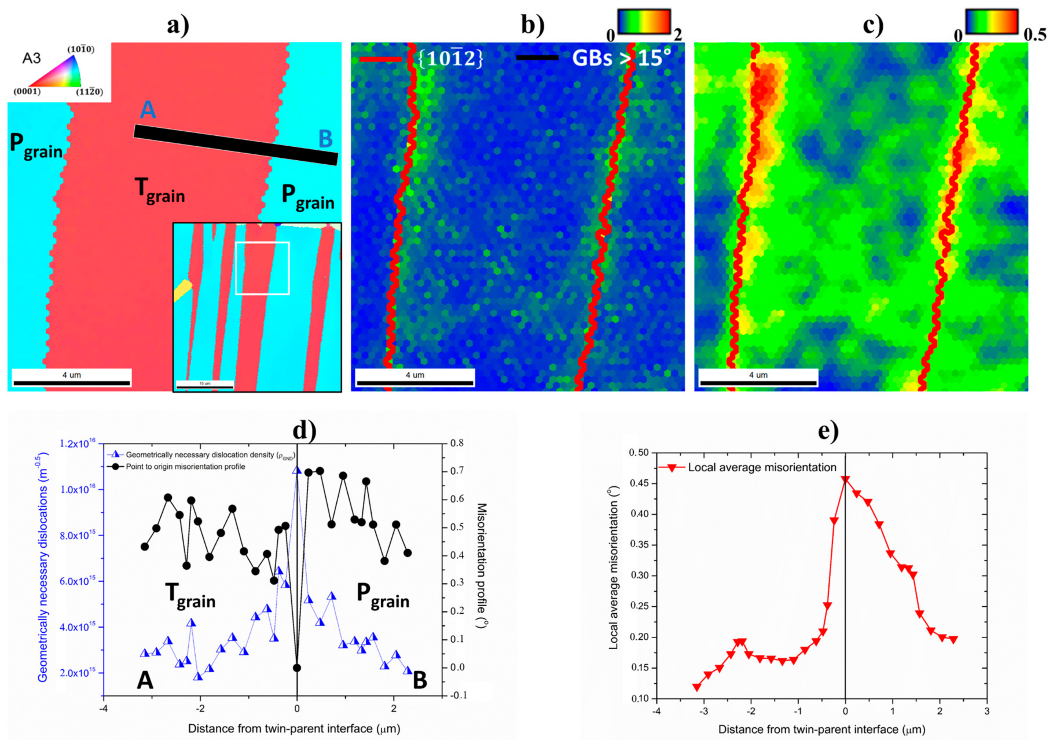
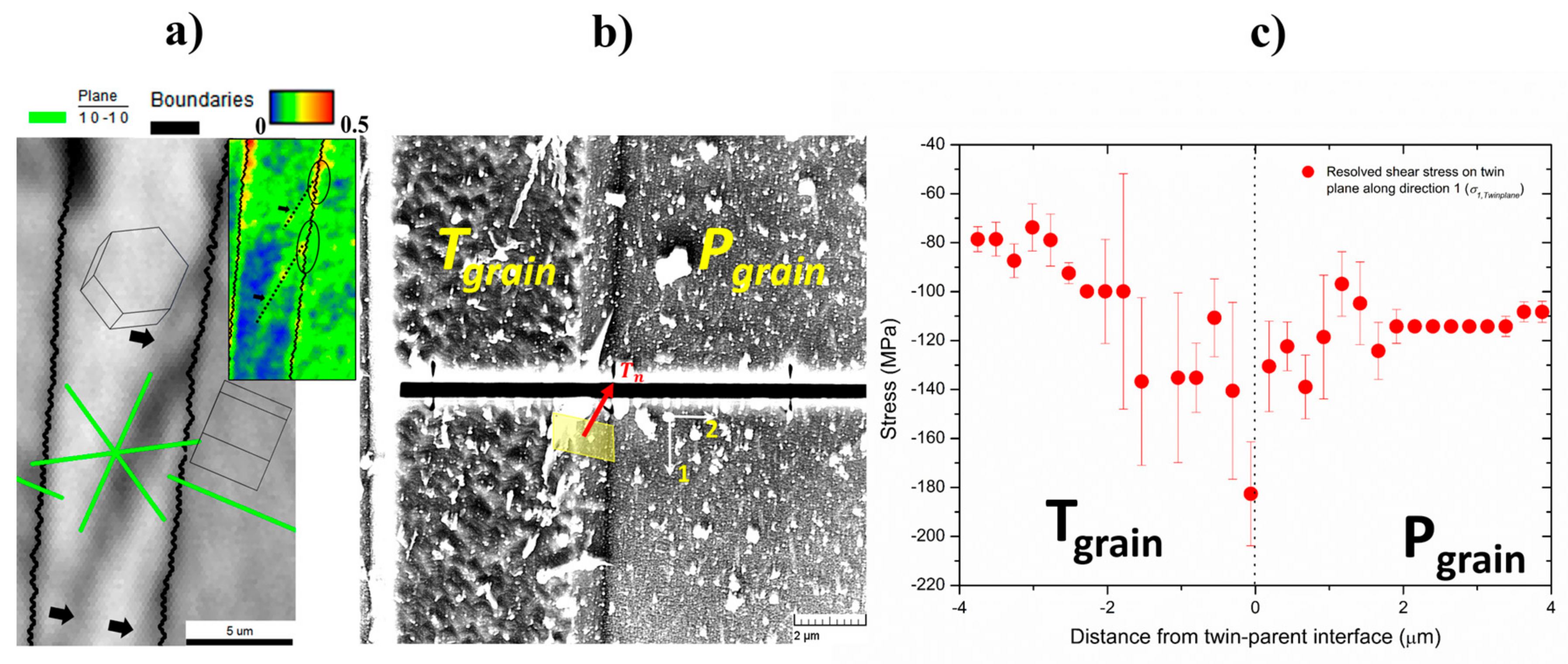
4.1. Stress Gradients across Twin-Parent Interface

Figure 4 illustrates a representative case of coherent twin-parent interface in titanium. Figure 4a shows the inverse pole figure (IPF) map of the highlighted twin boundary in the inset image. The viewing axis corresponds to the A3 direction. The twinned region and the parent grain are labelled as ‘Tgrain’ and ‘Pgrain’, respectively. While the c-axis of twinned grain is oriented parallel to the viewing axis, the parent grain was oriented such that its c-axis was aligned with the tensile axis. Figure 4a also shows the orientation of the milled slit lying between points A and B. Figure 4b,c represent the kernel average misorientation (KAM) and local average misorientation (LAM) mappings. The KAM physically describes the average misorientation spread between a reference pixel and its nearest neighbor pixels for a defined kernel size. The LAM angle corresponds to the misorientation averaged over all nearest neighbor pairs within a kernel. Both LAM and KAM values were calculated for the 2nd nearest neighbor with a threshold value of 2° [33]. { 10 1 ¯ 2 } Tension twin boundaries are shown in red in Figure 4b,c. The characterization of twins in the EBSD maps (c.f. Figure 4b,c) was done on the basis of the characteristic misorientation angle of 85.03° about the 11 2 ¯ 0 rotation axis (given in minimum angle-axis pair), which corresponds to { 10 1 ¯ 2 } 10 1 ¯ 1 . tension twin. A maximum angular deviation of ±6° was considered [34,35]. The KAM and LAM maps indicate signs of stress concentration at the interface.
Figure 4d shows the misorientation profile with respect to the interface along the twin grain and parent grain. The degree of misorientation between the twin center and the interface is of the order of ~0.6°, whereas between the boundary and parent grain interior is ~0.7°. GND density values are additionally shown as a function of distance from the twin-parent interface. GND density ( ρ G N D ) values from EBSD data were calculated using the strain gradient approach [36,37], given by the expression:
ρ G N D = 2 θ n λ | b d |
where θ is the experimentally measured KAM value, λ is the step size, n is the number of nearest neighbors averaged in the KAM calculation, and b d is the Burgers vector corresponding to the active slip system in the grain. It must be noted that the GND values obtained from Equation (4) provide a lower bound estimate as they can only account for contributions from the non-paired edge dislocation segments and dislocation walls (since both lead to an effective unclosed burgers circuit, thereby contributing to the measured local misorientation). Figure 4e displays the LAM values with respect to the distance from the twin-parent interface. The maximum LAM value is recorded at the boundary as 0.45°. Both the GND and LAM values decrease monotonically on moving away from the twin boundary. The excellent agreement between the LAM and GND values is not surprising since both values are derived from the measured local misorientation.
Figure 5a shows the interaction of ( 10 1 ¯ 0 )   prismatic slip bands with the twin-parent interface shown in Figure 4. The corresponding local misorientation gradient due to slip accumulation at the interface is shown in the inset LAM map. Figure 5b,c represents the FIB-DIC analysis and corresponding stress measurements for the region shown in Figure 4. Figure 5b shows the spatial orientation of the milled slit with respect to the twin boundary. The white dots correspond to the YSZ particles used for surface decoration. The twin boundary plane orientation is highlighted by the yellow parallelogram, with the twin plane normal defined as T n . The measured stress values were resolved along the twin plane to obtain the shear component acting on the twinning plane along the twin boundary trace, designated as σ 1 , T w i n p l a n e . Figure 5c displays the variation of σ 1 , T w i n p l a n e as a function of normal distance from the twin boundary i.e., along direction 2. The stress values all throughout the twin and parent remain compressive in nature, with a continuous transition across the interface. The magnitude of the stress is highest at the interface reaching up to a value of ~−180 MPa, subsequently dropping to −80 MPa near the twin center. On the other hand, the stress values in the parent grain interior stabilize at ~−110 MPa. On comparing the stress gradients with Figure 4d,e the agreement seems excellent, thereby indicating that the observed stress fluctuations indeed confer to the actual stress state in the twin and parent grains.
The observations indicate the presence of compressive residual stress states acting parallel to the twin boundary plane. In order to understand the implications of such a stress state it is important to delve into the mechanistic of migration of coherent twin-parent interfaces. The lateral broadening of a twin typically involves shear coupled migration of twin boundaries, whereby the normal translation of the boundaries is simultaneously accompanied by shearing of the parent grain. The magnitude of the theoretical twin shear S t is characteristic for the twin type and in the case of { 10 1 ¯ 2 } 10 1 ¯ 1 tension twins is given as: S t = ( c a ) 2 3 ( c a )   3 . For titanium with c/a = 1.587, St = 0.171.
Twin boundary motion typically involves the glide of twinning dislocations/zonal dislocations, which are defined as regions wherein non-homogeneous shear at the twin matrix interfaces is accomplished at the expense of pure atomic shuffling in multilayer twin lamellae (c.f. Figure 6a). The mechanism of lateral thickening is demonstrated in Figure 6a. During tensile loading, the stress component acting along the twin plane τ a p p l i e d typically drives the motion of twinning dislocations along the twin plane, resulting in shearing of the adjacent parent region and simultaneous thickening of the twin by a value Δ h . This process repeats itself as long as the applied stress is sufficient to move the twinning dislocations and sustain the thickening process. In the unloaded state however, the presence of a compressive residual stress state generates a negative shear that may promote the motion of twinning dislocations in a direction opposite to that in case for externally applied stress (c.f. Figure 6b). Such a scenario typically indicates the favorability of the twin lamellae to undergo thinning during unloading and also disappear when applied load is reversed. This further explains why lower applied stresses are required to activate de-twinning as compared to twin nucleation during cyclic loading behavior, since the already present internal compressive stresses act as an additive stress to the applied load [38,39]. Indeed, it must be noted that the considerations of anisotropy in twin boundary motion in the longitudinal and transverse directions, due to the former being shear dominated and the latter primarily driven by atomic shuffling, is also crucial to accurately understand the de-twinning phenomenon. In the forthcoming section, it will be also shown how the stress state at the twin tips further contribute to the aforementioned de-twinning effects, often observed in hexagonal close packed metals [40].

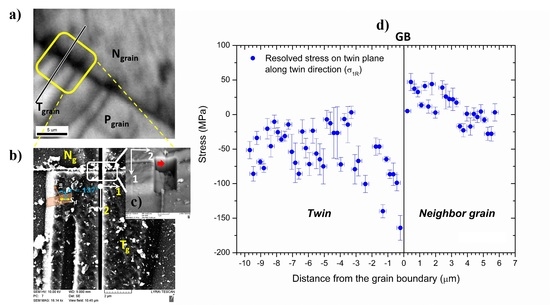
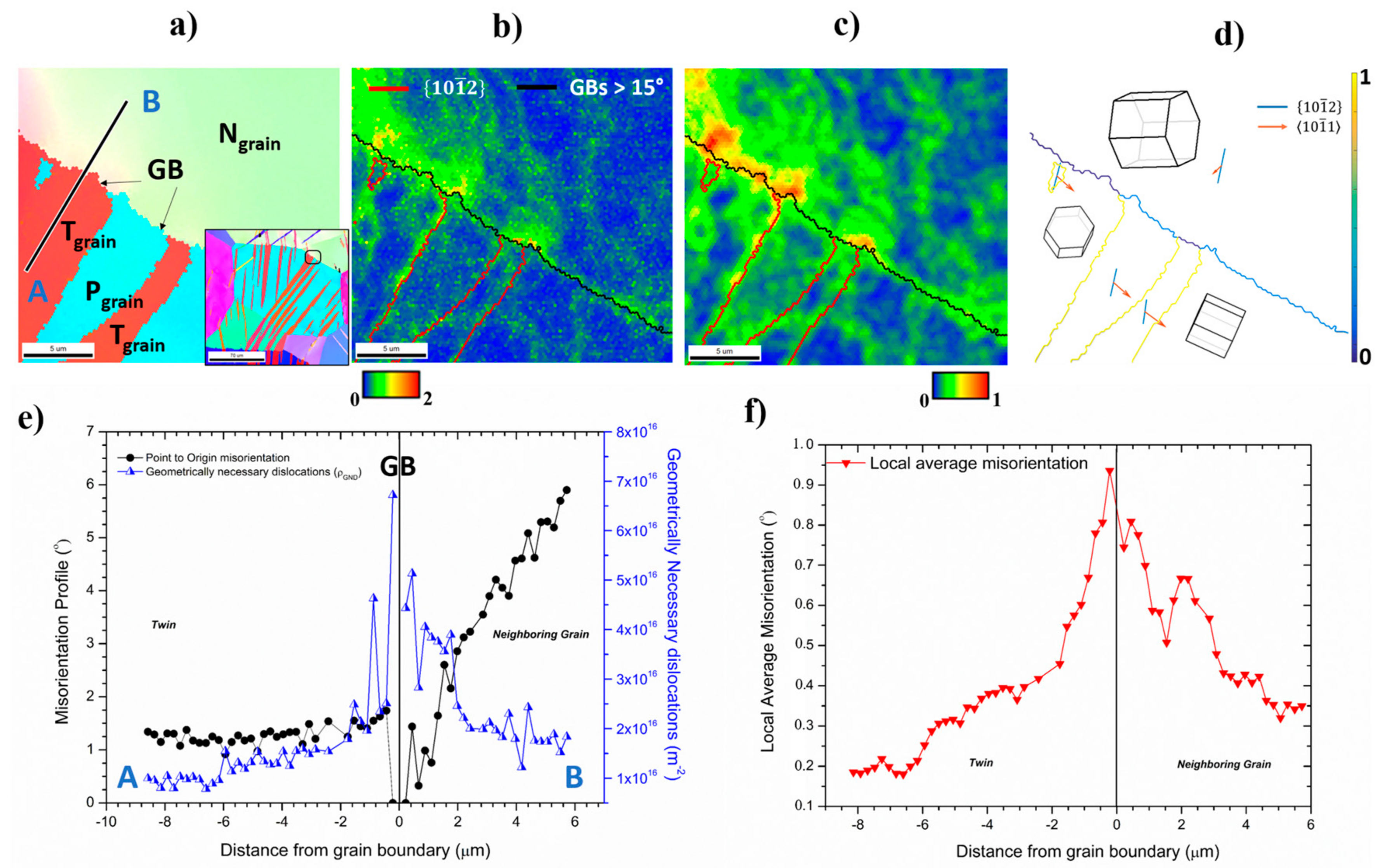
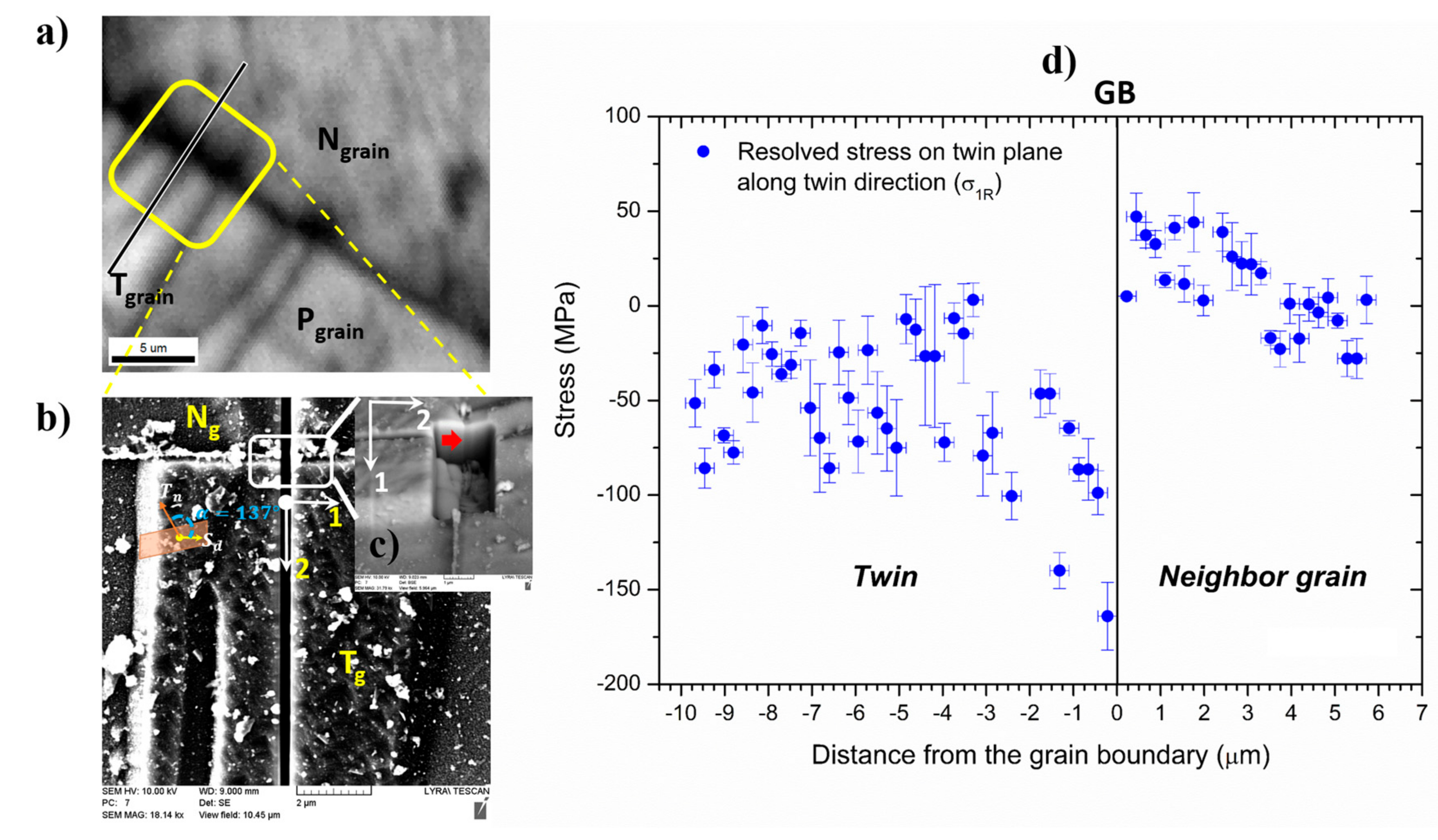
4.2. Stress Gradients Arising from Twin-Grain Boundary Interactions

Figure 7 illustrates an instance of twin-grain boundary interaction wherein { 10 1 ¯ 2 } tension twin lamellae impinge and are subsequently being blocked at the grain boundary. Figure 7a represents the inverse pole figure map of the twin-grain boundary intersection zone, wherein two tension twins of the same variant meet the grain boundary (marked as GB). The selected area corresponds to the magnified view of the highlighted region in the inset image. The inset image indicates that the investigated twin could either arise in the blue grain by means of propagation of the dark pink twin in the neighboring green grain across the grain boundary or due to simultaneous nucleation of twins at the grain boundary, which subsequently propagate inside both green and blue grains. As in Figure 4a, the parent grain is denoted as ‘Pgrain’, whereas the twinned domains are labelled as ‘Tgrain’ and the neighboring grain is represented as ‘Ngrain’. A schematic of the orientation of the milled slit from point A to B is additionally shown in Figure 7a. Figure 7b,c represent the KAM and LAM maps of the same region, with twin boundaries highlighted in red and grain boundaries shown in black. Grain boundaries were designated by a lower threshold of 15° in Figure 7b,c. A grain boundary map color coded with respect to the ease of twin transmission is presented in Figure 7d. The values at the grain boundary of interest indicate a poor probability of twin transfer, evident by an m value of 0.3 (c.f. Equation (1)). Grain and twin orientations are further depicted by the spatial orientation of the hexagonal crystals. Traces corresponding to the twin plane (in orange) and twin shear directions (in blue) are also plotted in Figure 7d. Figure 7e shows the distribution of GND values as well as the misorientation profile with respect to the grain boundary along line AB. Figure 7f indicates the LAM distribution along line AB. Figure 7e,f indicate a peak lattice distortion and dislocation density in the vicinity of the grain boundary that decays to lower values on moving left (towards twin interior) or right (into the neighboring grain). Lattice rotations inside the twin near the twin-grain boundary interface are significantly high and drop drastically, within a width of 1 μm away from the grain boundary. On the other hand, the strain gradient in the neighboring grain shows a less sharp decrease. The GND and LAM values in the neighbor grain indicate a local minimum in the vicinity of the grain boundary, within a width of 440 nm.
Figure 8 presents the stress measurements obtained from the FIB-DIC slit milling technique. Figure 8a presents the image quality map of the region shown in Figure 7a, with a schematic of the slit. The twins, parent and neighbor grains are labelled as Tgrain, Pgrain and Ngrain respectively. Figure 8b corresponds to an SEM image captured post slit milling of the region highlighted in Figure 8a. The twin boundary plane orientation is depicted and the corresponding inclination of the twinning plane normal with respect to the sample surface is measured as 137°. The twinning shear direction, Sd is aligned with the normal to the slit wall, represented by axis 1. The longitudinal axis of the slit is labelled as 2. Since the measured stress component from slit milling corresponds to σ 11 , the corresponding stress component lying on the twinning plane and in the direction of twinning shear can be described as σ 1 R   =   σ 11 * c o s 47 ° . Figure 8c shows the orientation of the grain boundary plane, marked by red arrow, to be perpendicular to the longitudinal axis of the slit, labelled as ‘2’. Figure 8d represents the measured profile of resolved stress on the twin plane along the twinning shear direction, σ 1 R along line AB. The stress gradients inside the twin domain reveal high compressive stresses at the twin tip, reaching values up to ~−170 MPa. On moving inwards, the stress values decrease considerably reaching values in the less negative/low positive range. On the other hand, the stress profile in the neighboring grain registers tensile stresses as high as ~50 MPa near the grain boundary that subsequently drop to very low positive values on moving away from the grain boundary. Agreeing with the trends seen in Figure 7e,f, the stress values in the neighbor grain show a local minimum near the grain boundary.
Residual stress profiles measured inside the twin and the neighbor grain indicate a sign reversal in stress states across the twin-grain boundary interface. Previous studies employing simulations also reported similar observations of sign reversal of stress states in twin and neighboring grains [41,42,43,44]. In general, grain orientations in low symmetry hexagonal crystals can be classified into crystallographically ‘soft’ or ‘hard’ orientations, depending on whether they are initially favorably oriented for strain accommodation along the <a>-axis (i.e., basal or prismatic slip) or not. { 10 1 ¯ 2 } tension twinning typically results when the local stress along the c-axis of a crystallographically ‘hard’ parent orientation is tensile in nature. Under an externally applied stress, the soft orientations are typically the first to yield while the hard grain orientations, being elastically stiffer, undergo elastic straining due to lack of slip accommodation. This mechanism continues until a threshold stress is reached, whereby twinning is able to activate in the crystallographic hard grain orientations. Twinning in hexagonal crystals proceeds primarily via 3 stages: nucleation, propagation and lateral growth of the twin lamella. Nucleation involves formation of viable twin nuclei, a few atoms thick, preferably at grain boundaries associated with high localized stress concentration. It has been suggested that the twin nucleation mechanism is triggered by the interaction of grain boundary dislocations and stress driven slip dislocations [40]. Typically, the nucleation process is governed by two main factors, that is, the local resolved shear stress along the twinning shear direction on the twin plane and the ease of accommodation of twin associated shear in the neighbor grain (either by twinning or dislocation slip). The accommodation strains imposed on the neighboring grains by twinning can be readily calculated from the twinning shear by rotating its displacement tensor into the crystallographic reference frame of the neighboring grain.
Following nucleation, the twin propagates along the longitudinal direction, elongating in shape (Figure 9a). The green arrows in Figure 9a,b indicate the direction of the applied stress in the current study. Propagation refers to the process of the twin front moving, by means of glide of twinning dislocations, into the bulk of the grain and eventually terminating on encountering an obstacle such as grain boundary. The orange arrow in Figure 9b indicates the direction of the resolved shear stress component that drives twin propagation. Hereafter, further stress increase triggers lateral growth of the twins leading to their thickening (Figure 9b). The mechanism of twin thickening is already described in Section 4.1 (c.f. Figure 6a).
While the part of the parent undergoing twinning undergoes significant stress relaxation, the untwinned parts of the parent grain, as well as the neighboring grains devoid of twinning show a significant increase in the internal stresses on further straining. Additionally, owing to the nearly 90° crystallographic reorientation of the twinned volume, the twins also assume a plastically hard orientation in terms of both slip as well as { 10 1 ¯ 2 } tension twinning (Figure 9b), leading to build up of large compressive internal stresses.
During unloading it is expected that the large internal stresses stored in the untwinned parent grain and the neighboring grains would impose considerable back stress on the twin (schematically illustrated by the blue arrows in Figure 9c), which explains the observed compressive stress state inside the twin domain (Figure 8d). The values of stresses near the twin tip in the present study reached values of −170 MPa. Comparing these values and the ones obtained in Section 4.1 to the typical critical resolved shear stresses for twinning in pure titanium that is around 125 MPa [45], indicates that the reaction stresses at the twin tips as well as along the twin boundary plane are significant enough to trigger mechanisms such as de-twinning in these regions. Furthermore, the high back stresses near the tips and low values at the mid region of the twin also comply with the typically seen lamellar twin morphology with converging tips (higher resistance to lateral growth) and a relatively thick mid-section (easier thickening under external stress).
The tensile stress gradient observed in the neighbor grain (Figure 8d) most likely arises from the forward stress component (Figure 9b) driving twin propagation (owing to the directional nature of twinning) and countering the aforementioned back stress. When the twin hits the grain boundary this positive stress in front of the twin tip is plastically accommodated in the neighboring grain, either by slip or twinning. In the present case absence of twins and a steady change in misorientation observed in the neighbor grain (c.f. Figure 7a–d) typically indicates slip induced strain accommodation. Similar to the observations in reference [15], the stress profile indicated a local minimum close to the boundary (Figure 8d). This characteristic is attributed to the role of stress fields arising from superposition of twinning dislocations and grain boundary dislocations, which in turn influence the pile-up configuration.

4.3. Implications for Macroscopic Damage Performance and Fatigue Behavior of Hexagonal Materials

The implications of the observations in the current work are significant in terms of understanding the role of twins on the fracture behavior in titanium. The findings indicate that stress development inside twins is significantly impacted by neighbor grain deformation as well as the plastic response of the untwinned parent. The values presented in the current study also highlight the role of twins in crack nucleation in the adjacent grain, especially at the twin tips. Furthermore, compressive back stresses acting parallel to the twin-parent interface in the unloaded state, along with the reaction forces at the twin tips explain the frequently observed dynamic microstructural changes induced due to internal back stresses during unloading via mechanisms such as, de-twinning or re-twinning [39,40]. The measured values also indicate that stresses can be significantly large to easily drive such reverse migration of twin boundaries, thereby corroborating the frequently observed behavior of twins disappearing during cyclical loading experiments.
The quantitative estimates of local stress profiles near twin boundaries provides an in depth understanding of microscale stress evolution, which is essential for designing microstructures that can enhance bulk scale mechanical performance.

5. Conclusions

A novel correlative technique utilizing EBSD and a FIB-DIC method for obtaining site specific microstructural and local stress information is presented. Stress gradients due to dislocation pile-up at pure titanium twin boundaries and at twin-grain boundary intersections are quantified. The following conclusions are drawn:
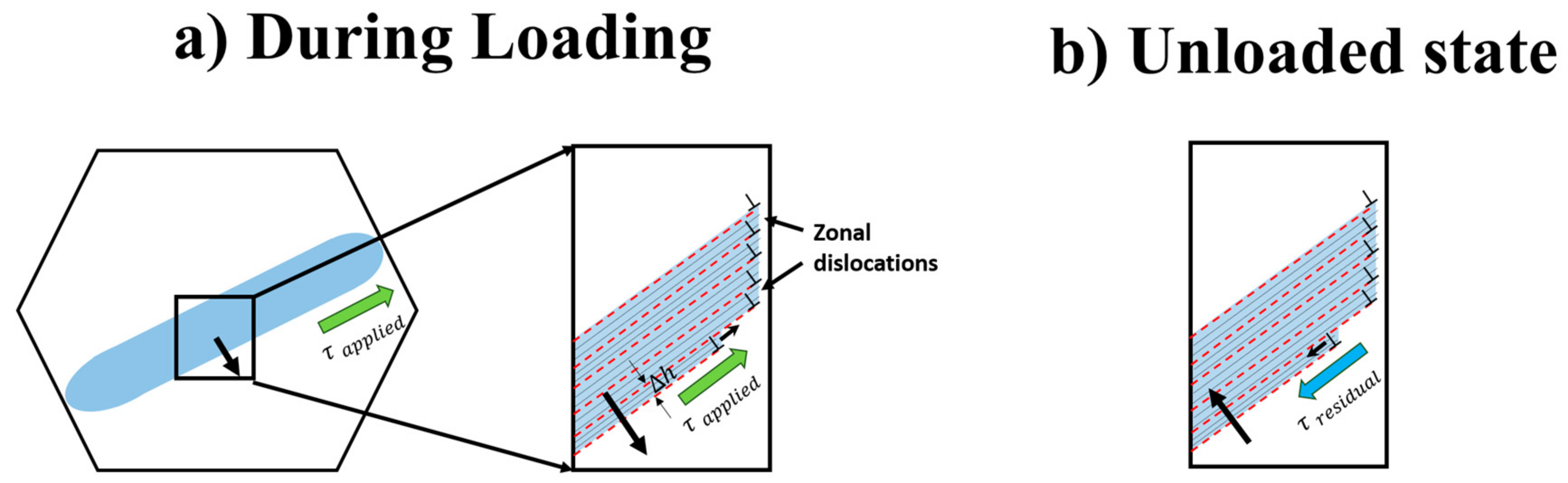
  • Stress gradients across the tension twin-parent interface were compressive in nature, with the maximum stresses recorded at the twin boundary. A resolved stress of ~−180 MPa acting along the twin boundary is reported. The results indicate that the in-built stresses are significant enough to promote reverse migration or de-twinning during reverse loading.
  • Stress profiles at twin grain boundary intersections show a sign reversal, being compressive inside the twin and tensile in the neighboring grain. The results provide a quantitative measure of back stresses exerted on the twin in unloaded condition (which reach values as high as ~−170 MPa near the twin tips) and stress gradients originating in the neighbor grain due to the interaction of twinning dislocations and a grain boundary.
  • The stress values at the twin tips and in the twin center also highlight the role of local stresses in defining the typically observed lamellar morphology of twins with wider mid-sections and converging tips.
  • The observations in the current work highlight the contribution of residual stresses associated with deformation twinning in hexagonal close packed metals in predicting their damage behavior.

Acknowledgments

This research was carried out under project number T61.1.14545 in the framework of the Research Program of the Materials Innovation Institute (M2i) (www.m2i.nl). The authors would like to acknowledge T.B. Britton for his valuable inputs in significantly improving the manuscript.

Author Contributions

Indranil Basu, Václav Ocelík and Herman Fidder conceived and designed the experiments. Indranil Basu and Herman Fidder performed the experiments. Indranil Basu, Herman Fidder, Václav Ocelík, and Jeff Th.M de Hosson contributed to the data analysis and scientific interpretation of the work. Indranil Basu drafted the article. Indranil Basu, Václav Ocelík and Jeff Th.M de Hosson made critical revisions to the the article.

Conflicts of Interest

The authors declare no conflict of interest.

References

  1. Nes, E.; Marthinsen, K. Modeling the evolution in microstructure and properties during plastic deformation of f.c.c.-metals and alloys—An approach towards a unified model. Mater. Sci. Eng. A 2002, 322, 176–193. [Google Scholar] [CrossRef]
  2. Eshelby, J.D.; Frank, F.C.; Nabarro, F.R.N. XLI. The equilibrium of linear arrays of dislocations. Lond. Edinb. Dublin Philos. Mag. J. Sci. 1951, 42, 351–364. [Google Scholar] [CrossRef]
  3. Hall, E.O. The Deformation and Ageing of Mild Steel: III Discussion of Results. Proc. Phys. Soc. Sect. B 1951, 64, 747. [Google Scholar] [CrossRef]
  4. Hall, E.O. Variation of Hardness of Metals with Grain Size. Nature 1954, 173, 948–949. [Google Scholar] [CrossRef]
  5. Petch, N.J. The Cleavage Strength of Polycrystals. J. Iron Steel Inst. 1953, 174, 25–28. [Google Scholar]
  6. Shen, Z.; Wagoner, R.H.; Clark, W.A.T. Dislocation and grain boundary interactions in metals. Acta Metall. 1988, 36, 3231–3242. [Google Scholar] [CrossRef]
  7. Clark, W.A.T.; Wagoner, R.H.; Shen, Z.Y.; Lee, T.C.; Robertson, I.M.; Birnbaum, H.K. On the criteria for slip transmission across interfaces in polycrystals. Scr. Metall. Mater. 1992, 26, 203–206. [Google Scholar] [CrossRef]
  8. Guo, Y.; Collins, D.M.; Tarleton, E.; Hofmann, F.; Tischler, J.; Liu, W.; Xu, R.; Wilkinson, A.J.; Britton, T.B. Measurements of stress fields near a grain boundary: Exploring blocked arrays of dislocations in 3D. Acta Mater. 2015, 96, 229–236. [Google Scholar] [CrossRef]
  9. Winiarski, B.; Withers, P.J. Novel implementations of relaxation methods for measuring residual stresses at the micron scale. J. Strain Anal. Eng. Des. 2015, 50, 412–425. [Google Scholar] [CrossRef]
  10. Britton, T.B.; Wilkinson, A.J. Measurement of residual elastic strain and lattice rotations with high resolution electron backscatter diffraction. Ultramicroscopy 2011, 111, 1395–1404. [Google Scholar] [CrossRef] [PubMed]
  11. Britton, T.B.; Wilkinson, A.J. Stress fields and geometrically necessary dislocation density distributions near the head of a blocked slip band. Acta Mater. 2012, 60, 5773–5782. [Google Scholar] [CrossRef]
  12. Guo, Y.; Britton, T.B.; Wilkinson, A.J. Slip band–grain boundary interactions in commercial-purity titanium. Acta Mater. 2014, 76, 1–12. [Google Scholar] [CrossRef]
  13. Jiang, J.; Britton, T.B.; Wilkinson, A.J. Mapping type III intragranular residual stress distributions in deformed copper polycrystals. Acta Mater. 2013, 61, 5895–5904. [Google Scholar] [CrossRef]
  14. Guo, Y.; Abdolvand, H.; Britton, T.B.; Wilkinson, A.J. Growth of {11‑22} twins in titanium: A combined experimental and modelling investigation of the local state of deformation. Acta Mater. 2017, 126, 221–235. [Google Scholar] [CrossRef]
  15. Basu, I.; Ocelík, V.; De Hosson, J.T.M. Measurement of spatial stress gradients near grain boundaries. Scr. Mater. 2017, 136, 11–14. [Google Scholar] [CrossRef]
  16. Basu, I.; Ocelík, V.; De Hosson, J.T.M. Experimental determination and theoretical analysis of local residual stress at grain scale. WIT Trans. Eng. Sci. 2017, 116, 3–14. [Google Scholar]
  17. Hirsch, J.; Al-Samman, T. Superior light metals by texture engineering: Optimized aluminum and magnesium alloys for automotive applications. Acta Mater. 2013, 61, 818–843. [Google Scholar] [CrossRef]
  18. Basu, I.; Gottstein, G.; Zander, B.D. Recrystallization Mechanisms in Wrought Magnesium Alloys Containing Rare-Earth Elements. Bachelor’s Dissertation, RWTH Aachen University, Aachen, Germany, December 2016. [Google Scholar]
  19. Basu, I.; Al Samman, T.; Gottstein, G. Recrystallization and Grain Growth Related Texture and Microstructure Evolution in Two Rolled Magnesium Rare-Earth Alloys. Mater. Sci. Forum 2013, 765, 527–531. [Google Scholar] [CrossRef]
  20. Basu, I.; Al-Samman, T. Triggering rare earth texture modification in magnesium alloys by addition of zinc and zirconium. Acta Mater. 2014, 67, 116–133. [Google Scholar] [CrossRef]
  21. Yoo, M.H. Slip, twinning, and fracture in hexagonal close-packed metals. Metall. Trans. A 1981, 12, 409–418. [Google Scholar] [CrossRef]
  22. Yoo, M.H.; Lee, J.K. Deformation twinning in h.c.p. metals and alloys. Philos. Mag. A 1991, 63, 987–1000. [Google Scholar] [CrossRef]
  23. El Kadiri, H.; Oppedal, A.L. A crystal plasticity theory for latent hardening by glide twinning through dislocation transmutation and twin accommodation effects. J. Mech. Phys. Solids 2010, 58, 613–624. [Google Scholar] [CrossRef]
  24. Qiao, H.; Guo, X.Q.; Oppedal, A.L.; El Kadiri, H.; Wu, P.D.; Agnew, S.R. Twin-induced hardening in extruded Mg alloy AM30. Mater. Sci. Eng. A 2017, 687, 17–27. [Google Scholar] [CrossRef]
  25. Taylor, B.; Weidmann, E. Metallographic Preparation of Titanium, Struers Application Notes; Struers: Ballerup, Denmark, 2008. [Google Scholar]
  26. Hielscher, R.; Schaeben, H. A novel pole figure inversion method: specification of the MTEX algorithm. J. Appl. Crystallogr. 2008, 41, 1024–1037. [Google Scholar] [CrossRef]
  27. Kang, K.J.; Yao, N.; He, M.Y.; Evans, A.G. A method for in situ measurement of the residual stress in thin films by using the focused ion beam. Thin Solid Films 2003, 443, 71–77. [Google Scholar] [CrossRef]
  28. Sabaté, N.; Vogel, D.; Gollhardt, A.; Marcos, J.; Gràcia, I.; Cané, C.; Michel, B. Digital image correlation of nanoscale deformation fields for local stress measurement in thin films. Nanotechnology 2006, 17, 5264. [Google Scholar] [CrossRef]
  29. Mansilla, C.; Martínez-Martínez, D.; Ocelík, V.; De Hosson, J.T.M. On the determination of local residual stress gradients by the slit milling method. J. Mater. Sci. 2015, 50, 3646–3655. [Google Scholar] [CrossRef]
  30. Mansilla, C.; Ocelík, V.; Hosson, J.T.M.D. A New Methodology to Analyze Instabilities in SEM Imaging. Microsc. Microanal. 2014, 20, 1625–1637. [Google Scholar] [CrossRef] [PubMed]
  31. Nelson, D.V.; Makino, A.; Schmidt, T. Residual Stress Determination Using Hole Drilling and 3D Image Correlation. Exp. Mech. 2006, 46, 31–38. [Google Scholar] [CrossRef]
  32. Britton, T.B.; Liang, H.; Dunne, F.P.E.; Wilkinson, A.J. The effect of crystal orientation on the indentation response of commercially pure titanium: experiments and simulations. Proc. R. Soc. Lond. Math. Phys. Eng. Sci. 2010, 466, 695–719. [Google Scholar] [CrossRef]
  33. Calcagnotto, M.; Ponge, D.; Demir, E.; Raabe, D. Orientation gradients and geometrically necessary dislocations in ultrafine grained dual-phase steels studied by 2D and 3D EBSD. Mater. Sci. Eng. A 2010, 527, 2738–2746. [Google Scholar] [CrossRef]
  34. Drouven, C.; Basu, I.; Al-Samman, T.; Korte-Kerzel, S. Twinning effects in deformed and annealed magnesium-neodymium alloys. Mater. Sci. Eng. A 2015, 647, 91–104. [Google Scholar] [CrossRef]
  35. Basu, I.; Al-Samman, T. Competitive twinning behavior in magnesium and its impact on recrystallization and texture formation. Mater. Sci. Eng. A 2017, 707, 232–244. [Google Scholar] [CrossRef]
  36. Kubin, L.P.; Mortensen, A. Geometrically necessary dislocations and strain-gradient plasticity: A few critical issues. Scr. Mater. 2003, 48, 119–125. [Google Scholar] [CrossRef]
  37. Konijnenberg, P.J.; Zaefferer, S.; Raabe, D. Assessment of geometrically necessary dislocation levels derived by 3D EBSD. Acta Mater. 2015, 99, 402–414. [Google Scholar] [CrossRef]
  38. Qiao, H.; Agnew, S.R.; Wu, P.D. Modeling twinning and detwinning behavior of Mg alloy ZK60A during monotonic and cyclic loading. Int. J. Plast. 2015, 65, 61–84. [Google Scholar] [CrossRef]
  39. Wu, L.; Agnew, S.R.; Brown, D.W.; Stoica, G.M.; Clausen, B.; Jain, A.; Fielden, D.E.; Liaw, P.K. Internal stress relaxation and load redistribution during the twinning–detwinning-dominated cyclic deformation of a wrought magnesium alloy, ZK60A. Acta Mater. 2008, 56, 3699–3707. [Google Scholar] [CrossRef]
  40. Basu, I.; Al-Samman, T. Twin recrystallization mechanisms in magnesium-rare earth alloys. Acta Mater. 2015, 96, 111–132. [Google Scholar] [CrossRef]
  41. Arul Kumar, M.; Kanjarla, A.K.; Niezgoda, S.R.; Lebensohn, R.A.; Tomé, C.N. Numerical study of the stress state of a deformation twin in magnesium. Acta Mater. 2015, 84, 349–358. [Google Scholar] [CrossRef]
  42. Arul Kumar, M.; Beyerlein, I.J.; McCabe, R.J.; Tomé, C.N. Grain neighbour effects on twin transmission in hexagonal close-packed materials. Nat. Commun. 2016, 7. [Google Scholar] [CrossRef] [PubMed]
  43. Knezevic, M.; Daymond, M.R.; Beyerlein, I.J. Modeling discrete twin lamellae in a microstructural framework. Scr. Mater. 2016, 121, 84–88. [Google Scholar] [CrossRef]
  44. Zhang, R.Y.; Daymond, M.R.; Holt, R.A. A finite element model of deformation twinning in zirconium. Mater. Sci. Eng. A 2008, 473, 139–146. [Google Scholar] [CrossRef]
  45. Wu, X.; Kalidindi, S.R.; Necker, C.; Salem, A.A. Prediction of crystallographic texture evolution and anisotropic stress‑strain curves during large plastic strains in high purity α-titanium using a Taylor-type crystal plasticity model. Acta Mater. 2007, 55, 423–432. [Google Scholar] [CrossRef]
Figure 1. (a) Local misorientation and stored dislocation densities in the vicinity of the grain boundary; (b) corresponding residual stress profile as a function of distance from the grain boundary; (c) variation of k H P   and relaxation width with the peak GND density measured in the vicinity of different grain boundaries (adapted from ref. [15]).
Crystals 08 00001 g001
Figure 2. Schematic of slit introduced by FIB milling.
Crystals 08 00001 g002
Figure 3. An arbitrary example illustrating the displacement field map from DIC analysis in GOM; image acquired over a field of view of ~28 µm, the color bar in the right side shows the magnitude of recorded surface displacements due to stress relaxation by FIB milling along direction x on both sides of the slit. The values range between −100 to +100 nm.
Crystals 08 00001 g003
Figure 4. (a) Inverse pole figure (IPF) map of twin lamellae intersecting a grain boundary; inset image shows a low magnification IPF map enclosing the area of interest highlighted in black square. Slit orientation between points A and B is shown schematically; parent and twin grains are labelled as Pgrain and Tgrain; (b) KAM and (c) LAM maps ( { 10 1 ¯ 2 } 10 1 ¯ 1 tension twin boundaries shown in red and high angle grain boundaries shown in black); (d) GND density and misorientation profile (with respect to the grain boundary) inside twin and neighbor grain; and (e) LAM profile between points A and B.
Crystals 08 00001 g004
Figure 5. (a) Image quality map showing instances of ( 10 1 ¯ 0 ) prismatic slip bands interacting with twin parent interface; inset image shows corresponding local misorientation gradient along the identified slip trace; (b) SEM image of decorated twin-parent interface from Figure 4a; the twin boundary plane orientation is shown in yellow with twin plane normal Tn. Slit coordinate system labelled by directions ‘1’ and ‘2’; (c) corresponding measured resolved shear stress component ( σ 1 , T w i n p l a n e ) along line AB.
Crystals 08 00001 g005
Figure 6. (a) Schematic showing twin boundary migration leading to twin broadening under applied stress; the stress component parallel to the twin boundary drives the motion of zonal dislocations that result in simultaneous shearing and twin thickening i.e., shear coupled twin boundary motion (b) In unloaded state, compressive residual stress states can exert negative shear forces and subsequently favor opposite movement of twinning dislocations and concurrent twin shrinkage i.e., de-twinning.
Crystals 08 00001 g006
Figure 7. (a) Inverse pole figure (IPF) map of twin lamellae intersecting a grain boundary; inset image shows a low magnification IPF map enclosing the area of interest highlighted in black square. Slit orientation between points A and B is shown schematically; parent, twin and neighbor grains are labelled as Pgrain, Tgrain and Ngrain; (b) KAM, (c) LAM and (d) m maps corresponding to twin transmission across grain boundary ( { 10 1 ¯ 2 } 10 1 ¯ 1 tension twin boundaries shown in red and high angle grain boundaries shown in black); (e) GND density and misorientation profile (with respect to the grain boundary) inside twin and neighbor grain and (f) LAM profile between points A and B.
Crystals 08 00001 g007
Figure 8. (a) Image quality map of region shown in Figure 7a with schematic of milled slit; (b) SEM image of decorated twin-grain boundary intersection from Figure 7a; twin boundary plane orientation is shown in orange with twin plane normal Tn and twin shear direction Sd. Slit coordinate system labelled by directions ‘1’ and ‘2’, measured angle between twin boundary normal and axis ‘1’ (normal to the slit wall) is displayed as 137°; (c) the orientation of the grain boundary plane (marked by red arrow) with respect to the slit length aligned normal to the wall of the milled trench; (d) corresponding measured resolved shear stress component (along the twinning plane in the direction of twinning shear) along line AB.
Crystals 08 00001 g008
Figure 9. (a) Schematic showing twin propagation in a parent grain, applied stress in the present study is depicted by green arrows, direction of propagation shown by black open arrow; (b) twin growth leads to lateral thickening under external stress once the twin hits the grain boundary, the forward stress component driving motion of twinning front (shown in blue arrow) is accommodated in the neighboring grain; (c) direction of back stresses acting on the twin in the investigated region during unloading that resist further twin growth.
Crystals 08 00001 g009

