Design of Polarization Splitter via Liquid and Ti Infiltrated Photonic Crystal Fiber


1
College of Physics and Optoelectronic Technology, Baoji University of Arts and Sciences, Baoji 721016, China
2
School of Engineering, University of South Wales, Cardiff CF37 1DL, UK
*
Authors to whom correspondence should be addressed.
†
These authors contributed equally to this work.
Crystals 2019, 9(2), 103; https://0-doi-org.brum.beds.ac.uk/10.3390/cryst9020103
Submission received: 31 January 2019
/
Revised: 14 February 2019
/
Accepted: 15 February 2019
/
Published: 18 February 2019
(This article belongs to the Special Issue Sonic and Photonic Crystals)
Abstract
:We propose a new polarization splitter (PS) based on Ti and liquid infiltrated photonic crystal fiber (PCF) with high birefringence. Impacts of parameters such as shape and size of the air holes in the cladding and filling material are investigated by using a vector beam propagation method. The results indicate that the PS offers an ultra-short length of 83.9 μm, a high extinction ratio of −44.05 dB, and a coupling loss of 0.0068 dB and at 1.55 μm. Moreover, an extinction ratio higher than −10 dB is achieved a bandwidth of 32.1 nm.
1. Introduction
Photonic crystal fiber (PCF) consists of a solid core and holes arranged in the cladding region non-periodically or periodically along the axis [1]. According to the mechanism of light transmission, PCF can be divided into refractive index guided PCF and photonic bandgap PCF. The refractive index guided PCF is similar to total internal reflection in the mechanism of light transmission. At present, refractive index guided PCF is the most mature and widely used optical fiber. PCF technology has made great progress in pharmaceutical drug testing, astronomy, communication, and biomedical engineering and sensing [2,3,4,5,6,7,8]. In recent years, the PCFs filled with materials have attracted great interests, because PCFs could provide excellent properties by filling different functional materials into the air holes [9,10,11,12,13,14]. Metal wire was filled into the air holes of PCFs for polarization splitting (PS) by Sun et al. and Fan et al. [10,11]. PCFs present high-quality channels that can be controllably filled with ultra-small volumes of analytes (femtoliter to subnanoliter), such as water [12], alcohol [13], and nematic liquid crystal [14].
The dual-core PCF is constructed by introducing two defect states in the periodic arrangement of air holes. When a polarized light beam is projected into the dual-core PCF with high birefringence, the coupling strength of two vertical polarization modes is weakened by the high birefringence [15]. Therefore, high birefringence could increase the difference in coupling length of the x-polarized mode and y-polarized mode of PCF, which is also beneficial to the miniaturization of PS. In general, high-birefringence fiber can be gained by breaking the symmetry implementing asymmetric defect structures, such as dissimilar air holes and elliptical holes along the two orthogonal axes, and asymmetric core design [16,17,18]. Another kind of high-birefringence fiber can also be manipulated by filling liquid into the air holes or hollow core [19]. At present, the dual-core PCF has a very mature application in polarization beam splitters.
The polarization handling devices based on PCFs filled with material, such as polarization splitters (PS) [20,21,22] and polarization rotators (PR) [23,24], have important applications in optical fiber sensing [25,26]. The PS could be divided into two fundamental modes ( and ) and propagate them in different directions. Its characteristics allow for significant applications in optical sensing, storage systems, communication systems, and integrated circuit systems [23,27]. In recent years, various PS structures based on PCFs have been reported in the literature [28,29,30,31,32,33,34,35]. These PS structures show good performance (see Table 1), such as an ultra-short length [31,32,33], a high extinction ratio [32], a low coupling loss [30,34], and an ultra-broad bandwidth [20,24,34], but these PS structures do not present these excellent properties at the same time. It is critical to design high-performance PS with ultra-short length, high extinction ratio, and low coupling loss [23]. In order to obtain a high-performance PS, we decided to use PCF filled with functional materials. It is well known that Ti demonstrates outstanding physical and chemical properties, such as light weight, anti-corrosion, biocompatibility, high melting point, durability, and high strength in extreme environments [36,37,38].
In this paper, a novel ultra-short PS with low coupling loss and high birefringence is proposed based on the idea of material filled PCFs by using a vector beam propagation method (BMP) [39,40,41]. The numerical results present a 0.0839 mm-long PS with a coupling loss of 0.0068 dB and a high extinction ratio of −44.05 dB at the wavelength of 1.55 μm. Moreover, an extinction ratio higher than −10 dB is achieved at a bandwidth of 32.1 nm.
2. Physical Modeling
The physical modeling of the proposed PS is shown in Figure 1. The BPM-based commercially state-of-the-art software RSoft (Synopsys Inc., Mountain View, CA, USA) can be used to design and analyze optical telecommunication devices, optical systems and networks, optical components used in semiconductor manufacturing, and nano-scale optical structures. Figure 1 shows the structure of PS, where d, d1, d2, and d3 represent the diameters of various air holes, respectively; a and b are the major and minor axes of the elliptical air hole; Λ represents distance of hole and hole (period); the ellipticity is expressed as η = b/a; and the air-filling ratio is d/Λ. The refractive index of background material is set as 1.45. Ti is filled into the two yellow air holes, and liquid (ethanol) is filled into the six blue holes. For ethanol (C2H5OH), variation of refractive index as a function of wavelength at a temperature of 20 °C is given by Reference [42].
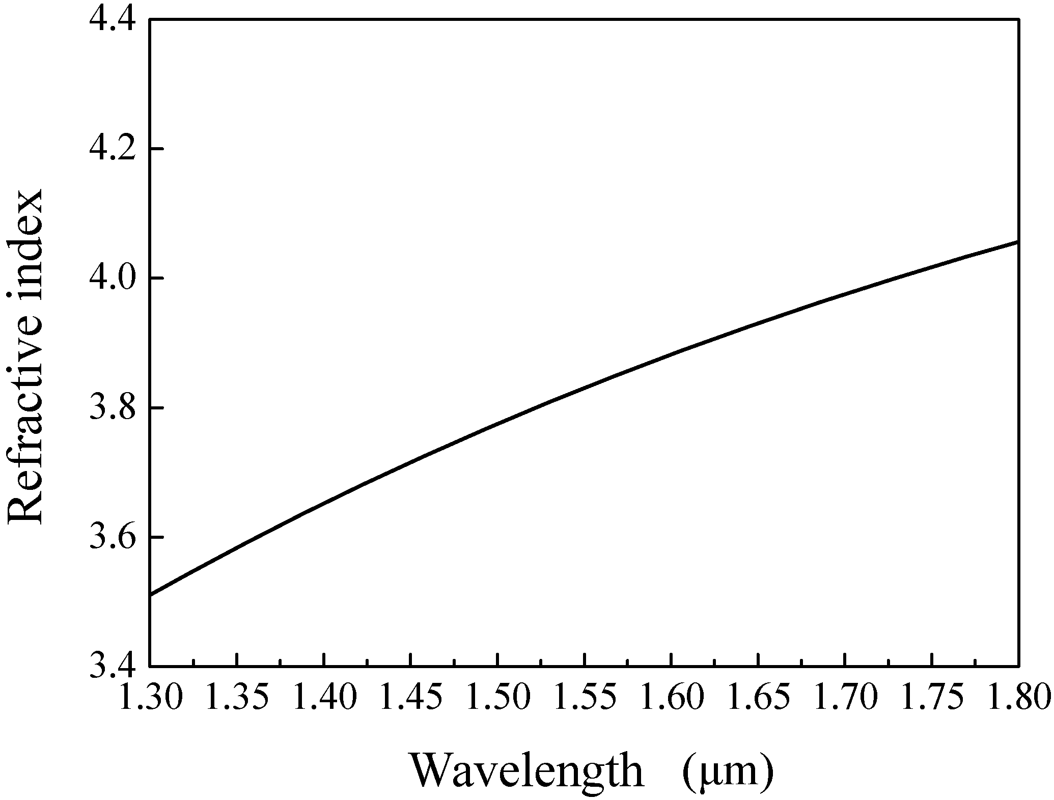
where λ represents wavelength of the propagating light. The refractive index of ethanol is set as 1.35 at 1.55 μm. Figure 2 shows the refractive index function of Ti versus wavelength [43].
The vector wave equation, which is the basis of BPM [39,40,41], can be expressed by
where . These two equations are known as the Helmholtz equations.
The electric field E(x, y, z) can be separated into two parts: the fast change term of exp(-ikn0z) and the envelope term of ϕ(x, y, z) of slow change in the axial direction; n0 is a refractive index in the cladding. Then, E(x, y, z) is stated as
Substituting Equation (4) in Equation (1) results in
Assuming the weakly guiding condition, we can approximate . Then Equation (5) can be rewritten as
A similar expression can be written for H. We find that if the fields vary in the transverse direction to propagation. Light propagation in various kinds of waveguides can be analyzed by the above method.
There are four modes of dual-core PCF on the basis of the principle of coupling mode, namely, even-mode of x-polarization, odd-mode of x-polarization, even-mode of y-polarization, and odd-mode of y-polarization. The coupling length has been defined by Reference [44] as
where denote the effective indexes of even-mode of x-polarization, odd-mode of x-polarization, even-mode of y-polarization, and odd-mode of y-polarization, respectively. When the coupling length of dual-core PCF satisfies L = m = n , the x-polarization and y-polarization launched into core A or B can be divided [33]. Hence, the coupling ratio (CR) can be defined as
Assuming that the incident power is coupled into a certain core, the output power of x- or y-polarized light in the core can be expressed by the following equation [45]:
where the transmission distance is denoted by z.
The extinction ratio is an important index to evaluate the performance of polarization splitter, which is expressed as
where represent the output energy of x-polarization and y-polarization, respectively [16,46].
The coupling loss of the PS can be described by
where is the fundamental mode power at the input core [30].
Birefringence can be expressed as
where nx and ny are the effective refractive index of x-polarized and y-polarized fundamental modes [29].
3. Results and Discussion
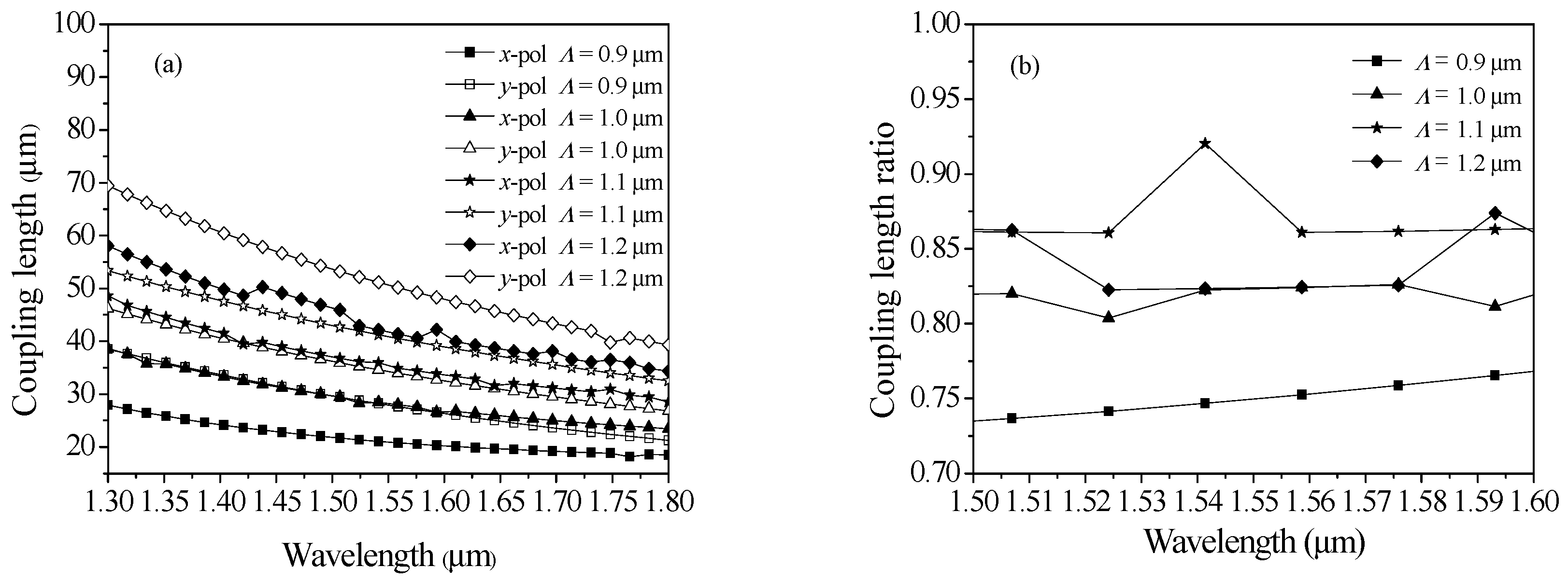
First, the Lc and CR are examined for different period Λ, where d1 = 0.8 μm, d/Λ = 0.7, d2 = 0.7 μm, η = 0.8, and d3 = 0.6 μm. The results are shown in Figure 3a, in which it is observed that the Lc is decreased when wavelength is increased for a constant period Λ. We also noticed that the Lc decreases with decreasing period Λ. Moreover, the coupling length of y-polarization is longer than the coupling length of x-polarization. As the period increases, the coupling between the cores becomes difficult. Hence, the Lc increases with the increase of the period. Interestingly, from Figure 3b, we noticed that when Λ ≤ 1.1 μm, the size of the CR is higher for higher period Λ; when Λ ≥ 1.1 μm, the size of the CR is higher for lower period Λ. According to Equation (8), when the CR is 3/4, the effective separation of the two orthogonal polarized lights can be achieved, so we choose the period value of 0.9 μm.
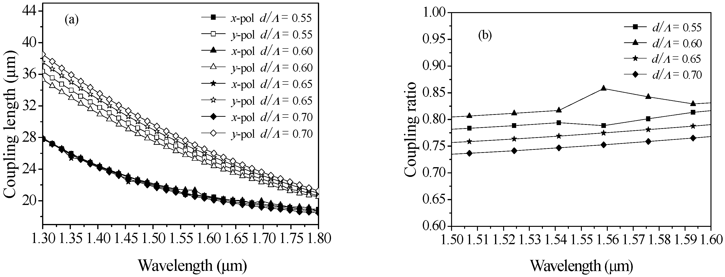
Next, we analyze the Lc and CR as a function of wavelength for different air-filling ratio d/Λ, when η = 0.8, d2 = 0.7 μm, Λ = 0.9, d3 = 0.6 μm, and d1 = 0.8 μm. From Figure 4a, it is observed that Lc is decreased when wavelength is decreased for the same value of air-filling ratio d/Λ. Moreover, we can find that the Lc decreases as the value of air-filling ratio increases, when air-filling ratio d/Λ ≤ 0.6. This is owing to the restriction of the outer cladding to the light wave being enhanced as air-filling ratio increases. However, when d/Λ ≥ 0.6, the result is opposite to the above. Meanwhile, the coupling length of y-polarization is longer than the coupling length of x-polarization. According to Figure 4b, it is found that when air-filling ratio d/Λ ≤ 0.6, the size of the CR is higher for higher air-filling ratio d/Λ; when air-filling ratio d/Λ ≥ 0.6, the size of the CR is higher for lower air-filling ratio d/Λ. When we choose an air-filling ratio d/Λ of 0.7, the CR is approximately 3/4 at 1.55 μm.
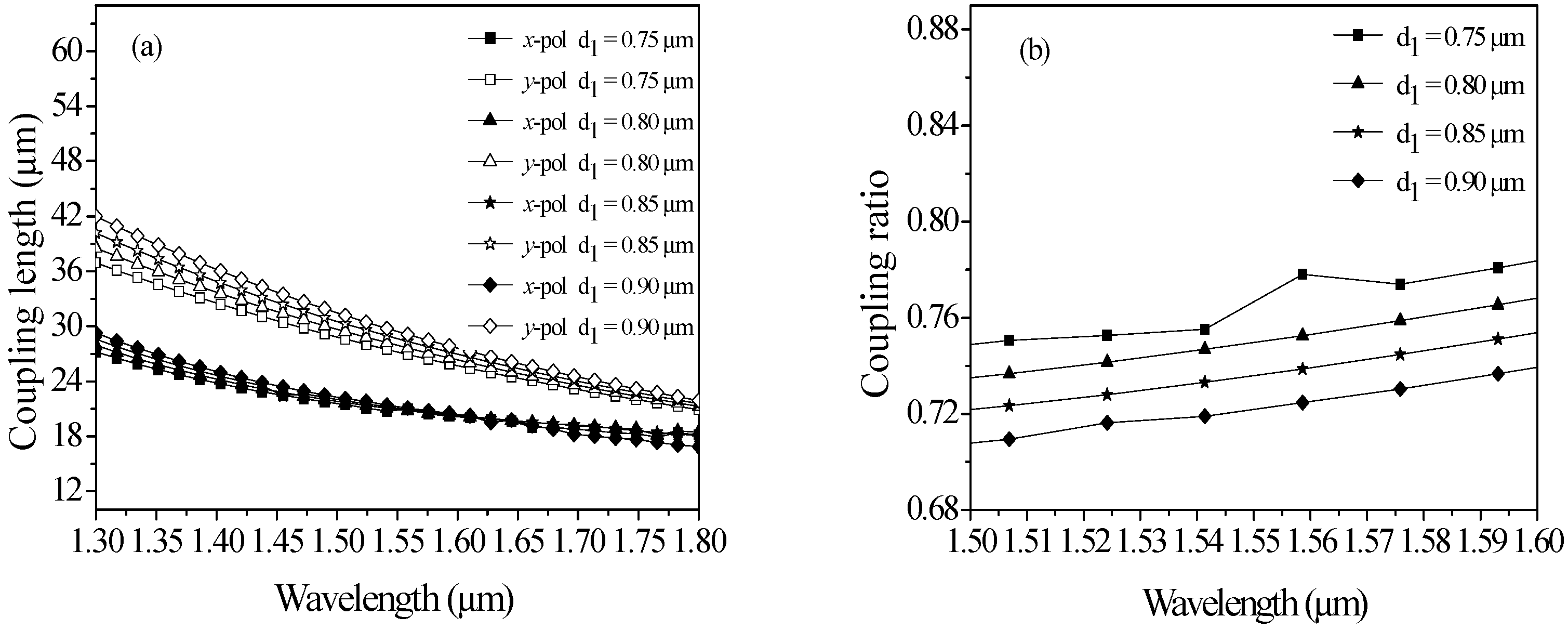
Additionally, from Figure 5a, Lc is shown as a function of d1, in which it is observed that the coupling length is increased if d1 is increased. This phenomenon can be interpreted as the following: as the value of d1 increases, the cores of PS can be compressed in the vertical direction, and fundamental modes in the horizontal direction will expand. Figure 5a also indicates that x-polarized coupling length is lower than y-polarized coupling length. As seen in Figure 5b, the size of the CR increases with increasing wavelength. According to the above discussed results, we determine that d1 is 0.8 μm.
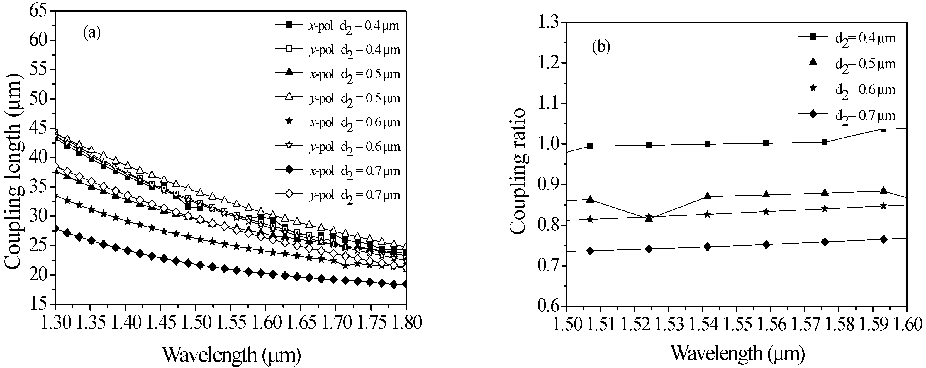
Figure 6 shows d2 dependence on the Lc (Figure 6a) and CR (Figure 6b). From Figure 6a, it is evident that the decreases with increasing the value of d2. This result can be attributed to the following process: as the value of d2 increases, the cores of PS can be compressed in the vertical direction, resulting in the increase of coupling length of y-direction. The is shown as a function of d2 in Figure 6a, in which it is observed that for d2 ≤ 0.5 μm, the value of CR is higher for higher d2; for d2 ≥ 0.5 μm, the value of the CR is higher for lower d2. This phenomenon is probably related to the ratio of compression. According to Figure 6b, we can clearly see that the size of the CR increases with a decrease of d2. When the CR is 3/4, the effective separation of the two orthogonal polarized lights can be achieved, so we choose the d2 value of 0.7 μm.
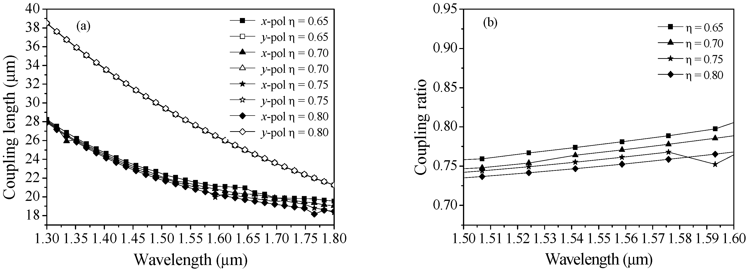
The Lc and CR with the variation of wavelength are demonstrated in Figure 7, when η = 0.65, 0.7, 0.75, and 0.8. It can be found that the Lc reduces with respect to wavelength. Figure 7a indicates that is higher than . It can also clearly be seen that the four y-polarized curves are extremely close to each other. This result can be explained that as the ellipticity η increases, the cores of PS can be compressed vertically, and the fundamental mode in the horizontal direction will expand, which makes the coupling of two cores easier. According to Figure 7b, the size of the CR increases with decreasing ellipticity η. According to the above discussed results, we determine that η is 0.8.
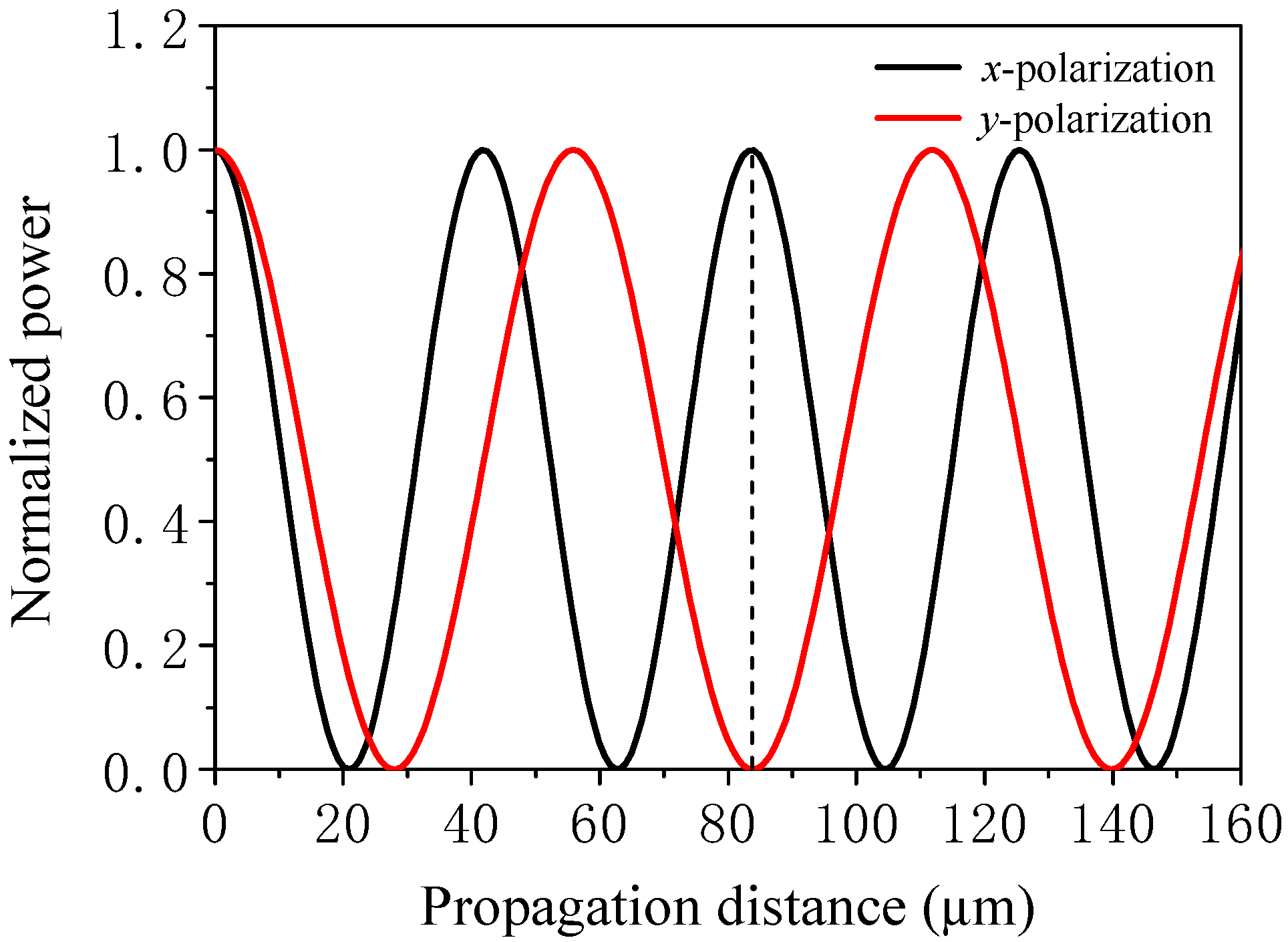
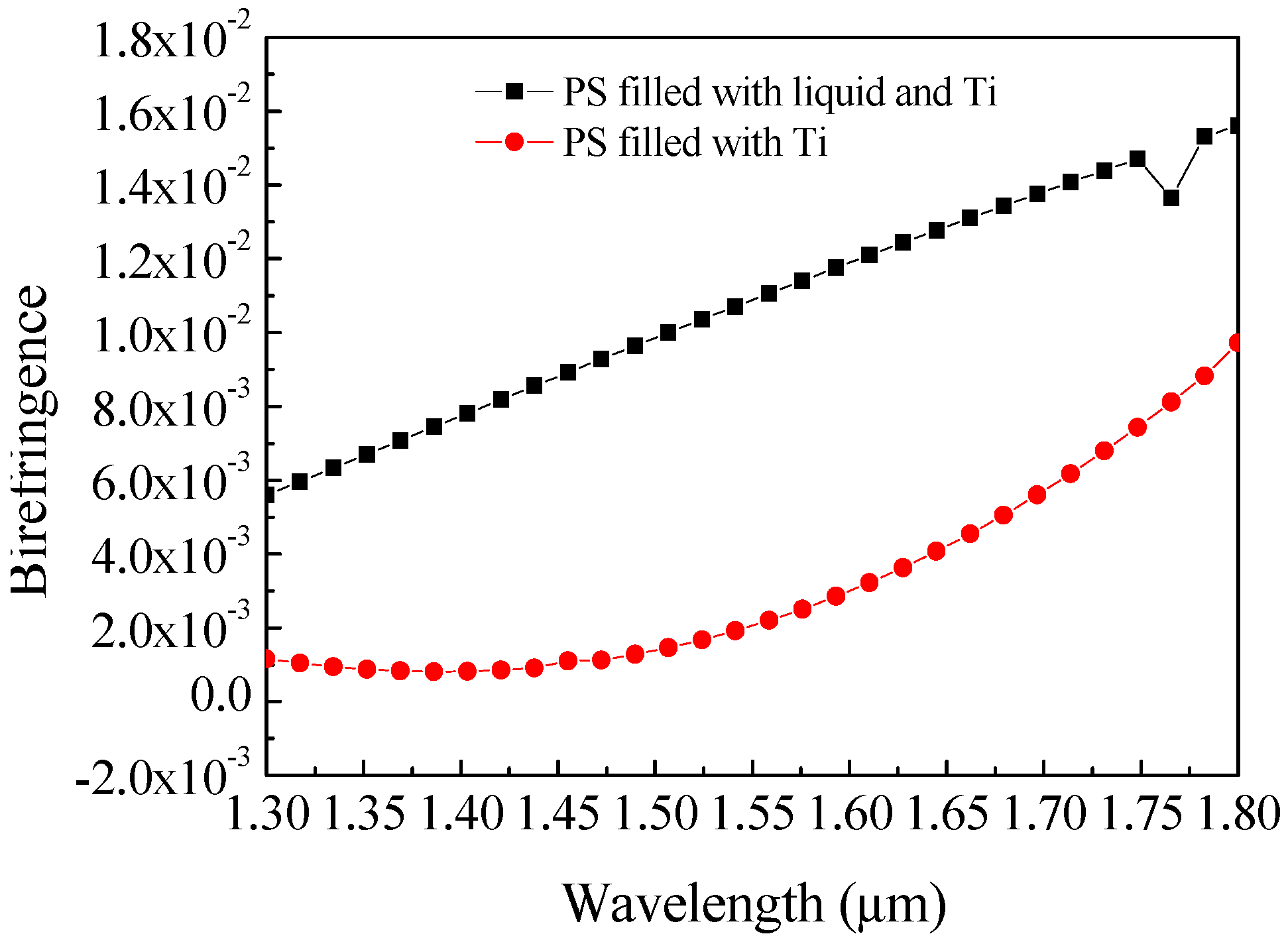
Finally, we found that the Lc and CR can both be impacted by d1, d2, d3, d/Λ, Λ, and η. Hence, there exist optimized structural parameters, namely, d1, d2, d3, Λ, d/Λ, and η is 0.8 μm, 0.7 μm, 0.6 μm, 0.9 μm, 0.7 and 0.8, respectively. Although the PS has many parameters, it can be easily influenced by the bulk polymerization process of polymers [47]. The optimized coupling length of x- and y-polarized direction are Lx = 20.91 μm and Ly = 27.96 μm at 1.55 μm, respectively. Figure 8 shows coupling characteristics of the PS. We observed that the separation of x- and y-polarized mode is achieved at the distance of 83.9 μm at 1.55 μm. Figure 9 shows the relationship between the birefringence and filling material for the optimized structural parameters. It is observed that birefringence of PS filled with liquid and Ti is higher than birefringence of PS filled with Ti. Meanwhile, the birefringence of PS filled with liquid and Ti can attain the order 10−2 at the wavelength of 1.55 μm, and the value of birefringence is about two orders of magnitude higher than that in References [29,48].
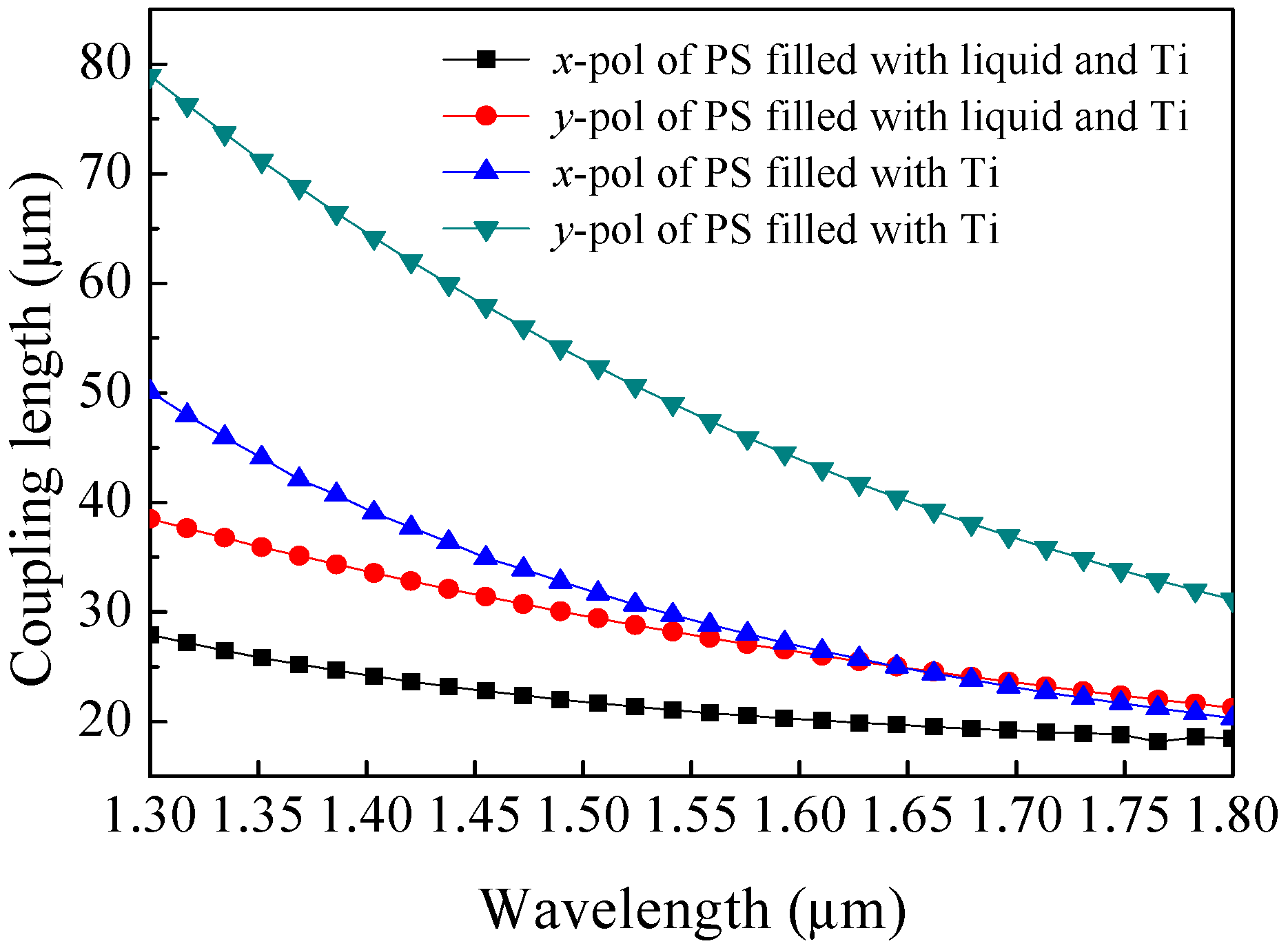
Figure 10 shows the variation of coupling length with filling material for the optimized structural parameters. It can be seen that the coupling length of the PS with filled Ti is higher the coupling length of the PS with filled liquid and Ti. For the PS with filled Ti, coupling length of x- and y-polarized direction are Lx = 29.25 μm and Ly = 48.28 μm at 1.55 μm, respectively. According to Equation (8), the length of the PS with filled Ti is about 234 μm, which is much longer than the PS with filled liquid and Ti. Therefore, the PS filled with liquid and Ti has a shorter length and higher birefringence than the PS filled with Ti.
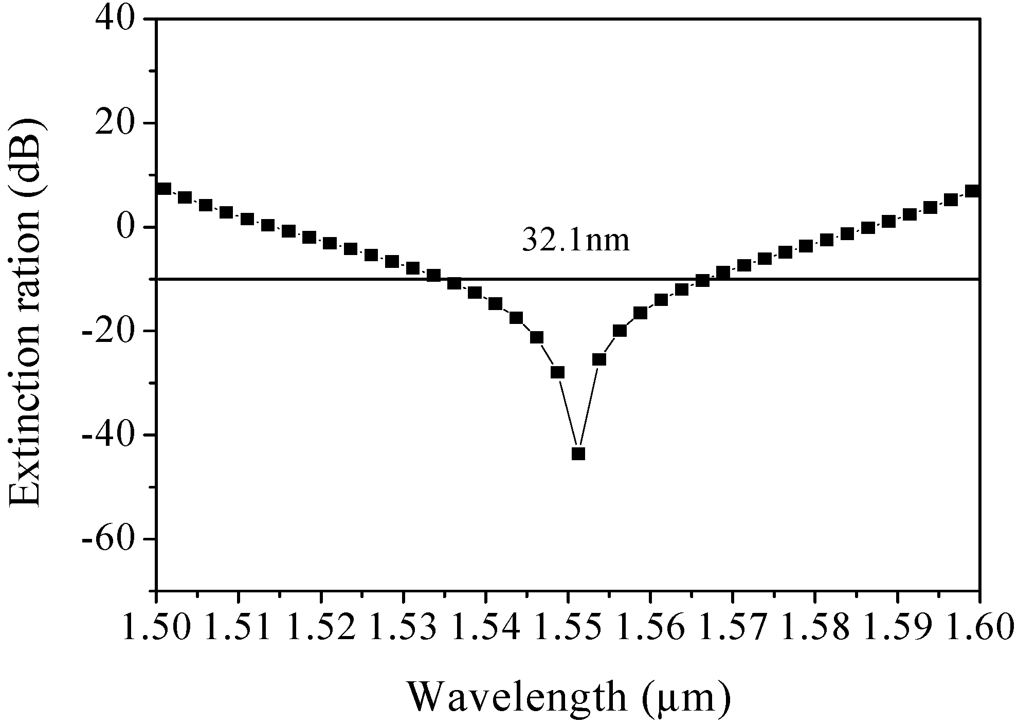
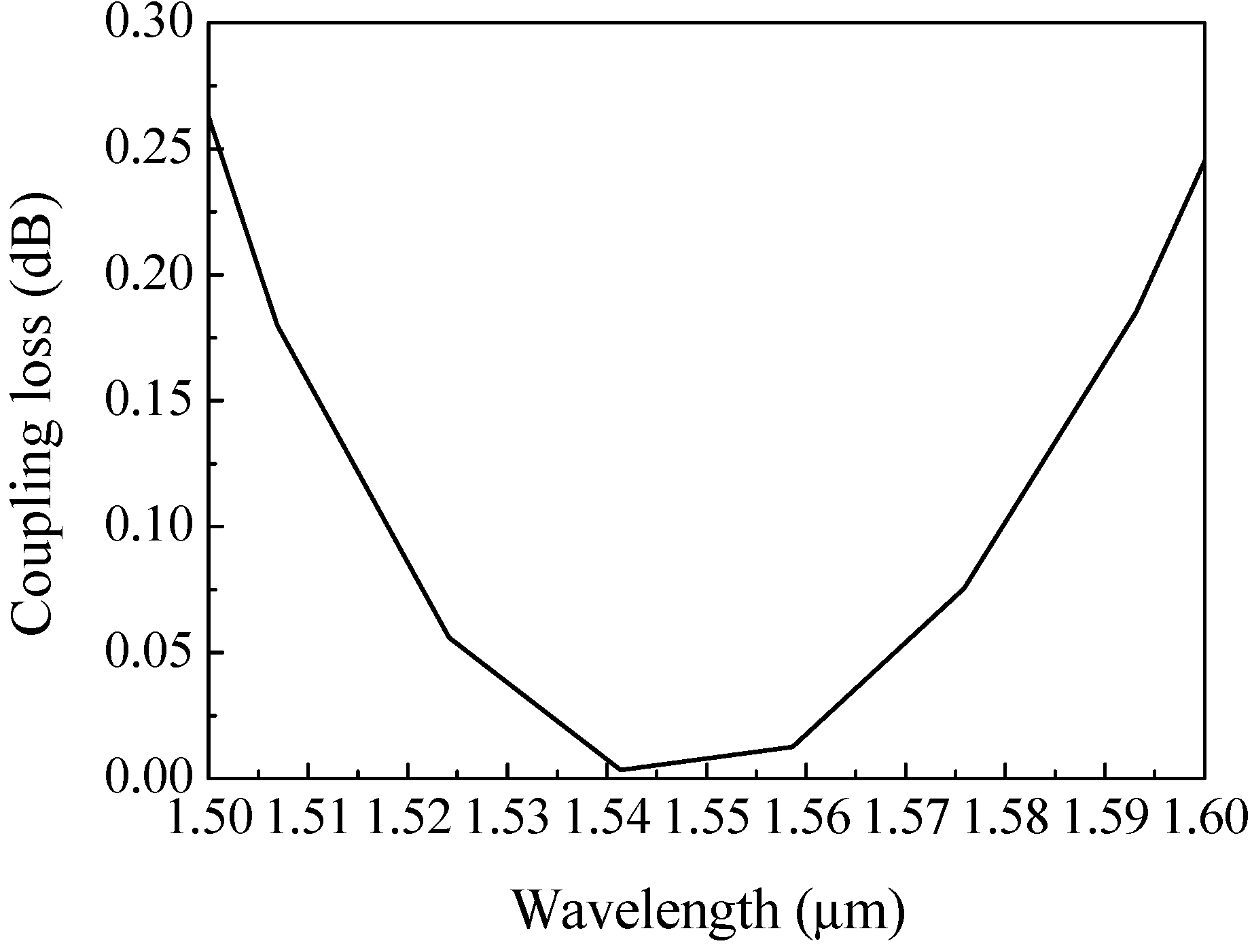
Figure 11 shows the extinction ratio of PS with respect to wavelength at optimized structural parameters. The extinction ratio is measured in dB according to Equation (10). The PS has an extinction ratio of −44.05 dB at 1.55 μm, an extinction ratio better than −10 dB, and a bandwidth of 32.1 nm from 1567 nm to 1535 nm. Figure 12 shows the coupling loss of PS as function of wavelength. We observe that the PS has a coupling loss of 0.0068 dB at 1.55 μm. Performances in factors such as the length, coupling loss, and bandwidth are better than or at the same order of magnitude as those of the early works mentioned above (see Table 1).
4. Conclusions
In conclusion, a novel ultra-short PS based on Ti and liquid infiltrated PCF with high birefringence have been demonstrated by using a vector beam propagation method. The designed PS shows an ultra-short length of 83.9 μm, a coupling loss of 0.0068 dB, a high extinction ratio of −44.05 dB, and a bandwidth of 32.1 nm at a wavelength of 1.55 μm. In addition, the birefringence of PS can attain the order 10−2 at the wavelength of 1.55 μm. The ultra-short PS with highly birefringent and low coupling loss properties is suitable for optical sensing, communication systems, storage systems, and integrated circuit systems.
Author Contributions
Analysis and writing, Q.X.; data curation, W.L.; project administration, S.L.; methodology, K.L. and N.C.
Funding
This work is supported by the National Natural Science Foundation of China (Grant No. 11647008) and the Scientific Research Program funded by Shaanxi Provincial Education Department (Grant No. 18JK0042).
Conflicts of Interest
The authors declare no conflicts of interest.
References
- Hu, D.J.J.; Pui, H. Recent advances in plasmonic photonic crystal fiber: Design, fabrication and applications. Adv. Opt. Photonics 2017, 9, 259–314. [Google Scholar] [CrossRef]
- Knight, J.C. Photonic crystal fiber. Nature 2003, 424, 847–851. [Google Scholar] [CrossRef]
- Russell, P. Photonic crystal fiber. Science 2003, 299, 358–362. [Google Scholar] [CrossRef] [PubMed]
- Kurokawa, K. Optical Fiber for High-Power Optical Communication. Crystals 2012, 2, 1382–1392. [Google Scholar] [CrossRef] [Green Version]
- Chiang, J. Analysis of Leaky Modes in Photonic Crystal Fibers Using the Surface Integral Equation Method. Crystals 2018, 8, 177. [Google Scholar] [CrossRef]
- Yu, Y.; Sun, B. Ultra-Wide-Bandwidth Tunable Magnetic Fluid-Filled Hybrid Connected Dual-Core Photonic Crystal Fiber Mode Converter. Crystals 2018, 8, 95. [Google Scholar] [Green Version]
- Zhang, H.; Zhang, X.; Li, H.; Deng, Y.; Xi, L.; Tang, X.; Zhang, W. The Orbital Angular Momentum Modes Supporting Fibers Based on the Photonic Crystal Fiber Structure. Crystals 2017, 7, 286. [Google Scholar] [CrossRef]
- Islam, M.S.; Sultana, J.; Dinovitser, A.; Faisal, M.; Islam, M.R.; Ng, B.W.; Abbott, D. Zeonex-based asymmetrical terahertz photonic crystal fiber for multichannel communication and polarization maintaining applications. Appl. Opt. 2018, 4, 666–672. [Google Scholar] [CrossRef]
- Liu, Q.; Li, S.; Shi, M. Fiber Sagnac interferometer based on a liquid-filled photonic crystal fiber for temperature sensing. Opt. Commun. 2016, 381, 1–6. [Google Scholar] [CrossRef]
- Sun, B.; Chen, M.; Zhang, Y.; Zhou, J. Polarization-dependent coupling characteristics of metal-wire filled dual-core photonic crystal fiber. Opt. Quantum Electron. 2015, 47, 441–451. [Google Scholar] [CrossRef]
- Fan, Z.; Li, S.; Liu, Q.; Chen, H.; Wang, X. Plasmonic broadband polarization splitter based on dual-core photonic crystal fiber with elliptical metallic nanowires. Plasmonics 2016, 11, 1565–1572. [Google Scholar] [CrossRef]
- Huang, Y.; Xu, Y.; Yariv, A. Fabrication of functional microstructured optical fibers through a selective-filling technique. Appl. Phys. Lett. 2004, 85, 5182–5184. [Google Scholar] [CrossRef]
- Sultana, J.; Islam, M.S.; Ahmed, K.; Dinovitser, A. Terahertz detection of alcohol using a photonic crystal fiber sensor. Appl. Opt. 2018, 57, 2426–2431. [Google Scholar] [CrossRef]
- Haakestad, M.W.; Alkeskjold, T.T.; Nielsen, M.D.; Scolari, L.; Riishede, J.; Engan, H.E.; Bjarklev, A. Electrically tunable photonic bandgap guidance in a liquid-crystal-filled photonic crystal fiber. IEEE Photonics Technol. Lett. 2005, 17, 819–821. [Google Scholar] [CrossRef]
- Fan, Z.; Li, S.; Zhang, W.; An, G.; Bao, Y. Analysis of the polarization beam splitter in two communication bands based on ultrahigh birefringence dual-core tellurite glass photonic crystal fiber. Opt. Commun. 2014, 333, 26–31. [Google Scholar] [CrossRef]
- Chen, M.; Yu, R.; Zhao, A. Highly birefringence rectangular lattice photonic crystal fiber. J. Opt. A Pure Appl. Opt. 2004, 6, 997–1000. [Google Scholar] [CrossRef]
- Kim, S.; Kee, C.; Lee, C.G. Modified rectangular lattice photonic crystal fibers with high birefringence and negative dispersion. Opt. Express 2009, 17, 7952–7957. [Google Scholar] [CrossRef]
- Yang, T.; Wang, E.; Jiang, H.; Hu, Z.; Xie, K. High birefringence photonic crystal fiber with high nonlinearity and low confinement loss. Opt. Express 2009, 23, 8329–8337. [Google Scholar] [CrossRef] [PubMed]
- Jiang, L.; Zheng, Y.; Yang, J.; Hou, L.; Li, Z.; Zhao, X. An ultra-broadband single polarization filter based on plasmonic photonic crystal fiber with a liquid crystal core. Plasmonics 2017, 12, 411–417. [Google Scholar] [CrossRef]
- Chiang, J.; Sun, N.; Lin, S.; Liu, W. Analysis of an ultrashort PCF-based polarization splitter. J. Lightw. Technol. 2010, 28, 707–713. [Google Scholar] [CrossRef]
- Wu, H.; Tan, Y.; Dai, D. Ultra-broadband high-performance polarizing beam splitter on silicon. Opt. Express 2017, 25, 6069–6075. [Google Scholar] [CrossRef] [PubMed]
- Jun, D.; Zhang, Z.; Zheng, H.; Sun, M. Recent progress on plasmon-enhanced fluorescence. Nanophotonics 2015, 4, 472–490. [Google Scholar]
- Zhang, Y.; He, Y.; Wu, J.; Jiang, X.; Liu, R.; Qiu, C.; Jiang, X.; Yang, J.; Tremblay, C.; Su, Y. High-extinction-ratio silicon polarization beam splitter with tolerance to waveguide width and coupling length variations. Opt. Express 2016, 24, 6586–6593. [Google Scholar] [CrossRef] [PubMed]
- Tanizawa, K.; Suzuki, K.; Ikeda, K.; Namiki, S.; Kawashima, H. Non-duplicate polarization-diversity 8 × 8 Si-wire PILOSS switch integrated with polarization splitter-rotators. Opt. Express 2017, 25, 10885–10892. [Google Scholar] [CrossRef]
- González-Vila, Á.; Kinet, D.; Mégret, P.; Caucheteur, C. Narrowband interrogation of plasmonic optical fiber biosensors based on spectral combs. Opt. Laser Technol. 2017, 96, 141–146. [Google Scholar] [CrossRef]
- Lu, X.; Soto, M.A.; Thévenaz, L. Temperature-strain discrimination in distributed optical fiber sensing using phase-sensitive optical time-domain reflectometry. Opt. Express 2017, 25, 16059–16071. [Google Scholar] [CrossRef]
- Huang, Z.; Yang, X.; Wang, Y.; Meng, X.; Fan, R.; Wang, L. Ultrahigh extinction ratio of polarization beam splitter based on hybrid photonic crystal waveguide structures. Opt. Commun. 2015, 354, 9–13. [Google Scholar] [CrossRef]
- Zhang, L.; Yang, C. Polarization splitter based on photonic crystal fibers. Opt. Express 2003, 9, 1015–1020. [Google Scholar] [CrossRef]
- Li, J.; Wang, J.; Wang, R.; Liu, Y. A novel polarization splitter based on dual-core hybrid photonic crystal fibers. Opt. Laser Technol. 2011, 43, 795–800. [Google Scholar] [CrossRef]
- Liu, S.; Li, S.; Yin, G.; Feng, R.; Wang, X. A novel polarization splitter in ZnTe tellurite glass three-core photonic crystal fiber. Opt. Commun. 2012, 285, 1097–1102. [Google Scholar] [CrossRef]
- Zi, J.; Li, S.; An, G.; Fan, Z. Short-length polarization splitter based on dual-core photonic crystal fiber with hexagonal lattice. Opt. Commun. 2016, 363, 80–84. [Google Scholar] [CrossRef]
- Xu, Z.; Li, X.; Ling, W.; Zhang, Z. Design of short polarization splitter based on dual-core photonic crystal fiber with ultra-high extinction ratio. Opt. Commun. 2015, 354, 314–320. [Google Scholar] [CrossRef]
- Jiang, H.; Wang, E.; Zhang, J.; Hu, L.; Mao, Q.; Li, Q.; Xie, K. Polarization splitter based on dual-core photonic crystal fiber. Opt. Express 2014, 22, 30461–30466. [Google Scholar] [CrossRef] [PubMed]
- Jiang, L.; Zheng, Y.; Hou, L.; Zheng, K.; Peng, J.; Zhao, X. An ultrabroadband polarization splitter based on square-lattice dual-core photonic crystal fiber with a gold wire. Opt. Commun. 2015, 351, 50–56. [Google Scholar] [CrossRef]
- Sheng, Z.; Wang, J.; Feng, R. Design of a compact polarization splitter based on the dual-elliptical-core photonic crystal fiber. Infrared Phys. Technol. 2014, 67, 560–565. [Google Scholar] [CrossRef]
- Vorobyev, A.Y.; Guo, C. Shot-to-shot correlation of residual energy and optical absorptance in femtosecond laser ablation. Appl. Phys. 2007, 86, 235–241. [Google Scholar] [CrossRef]
- Zinger, O.; Zhao, G.; Schwartz, Z.; Simpson, J.; Wieland, M.; Landolt, D.; Boyan, B. Differential regulation of osteoblasts by substrate microstructural features. Biomaterials 2005, 26, 1837–1847. [Google Scholar] [CrossRef]
- Ali, N.; Bashir, S.; Begum, N.; Rafique, M.S.; Husinsky, W. Effect of liquid environment on the titanium surface modification by laser ablation. Appl. Surf. Sci. 2017, 405, 298–307. [Google Scholar] [CrossRef]
- Feit, M.D.; Fleck, J.A., Jr. Light propagation in graded-index optical fiber. Appl. Opt. 1978, 24, 3990–3998. [Google Scholar] [CrossRef]
- Xiao, J.; Sun, X. A Modified full-vectorial finite-difference beam propagation method based on H-fields for optical waveguides with step-index profiles. Opt. Commun. 2006, 266, 505–511. [Google Scholar] [CrossRef]
- Xie, K.; Boardman, A.D.; Xie, M.; Yang, Y.J.; Jiang, H.M.; Yang, H.J.; Wen, G.J.; Li, J.; Chen, K.; Chen, F.S. A Simulation of longitudinally magnetized three-dimensional magneto-optical devices by a full-vectorial beam propagation method. Opt. Commun. 2008, 281, 3275–3285. [Google Scholar] [CrossRef]
- Sani, E.; Dell’Oro, A. Spectral optical constants of ethanol and isopropanol from ultraviolet to far infrared. Opt. Mater. 2016, 60, 137–141. [Google Scholar] [CrossRef]
- Rakić, A.D.; Djurišic, A.B.; Elazar, J.M.; Majewski, M.L. Optical properties of metallic films for vertical-cavity optoelectronic devices. Appl. Opt. 1998, 37, 5271–5283. [Google Scholar] [CrossRef] [PubMed]
- Saitoh, K.; Sato, Y.; Koshiba, M. Coupling characteristics of dual-core photonic crystal fiber couplers. Opt. Express 2003, 11, 3188–3195. [Google Scholar] [CrossRef]
- Eisenmann, M.; Weidel, E. Single-mode fused biconical coupler optimized for polarization beam splitting. J. Lightw. Technol. 1991, 9, 853–858. [Google Scholar] [CrossRef]
- Saitoh, K.; Sato, Y.; Koshiba, M. Polarization splitter in three-core photonic crystal fibers. Opt. Express 2004, 12, 3940–3946. [Google Scholar] [CrossRef]
- Zhang, Y.; Li, K.; Wang, L.; Ren, L.; Zhao, W.; Miao, R.; Large, M.C.J.; Eijkelenborg, M.A.V. Casting preforms for microstructured polymer optical fibre fabrication. Opt. Express 2006, 14, 5541–5547. [Google Scholar] [CrossRef]
- Chen, X.; Li, M.; Koh, J.; Nolan, D.A. Wide band single polarization and polarization maintaining fibers using stress rods and air holes. Opt. Express 2008, 16, 12060–12068. [Google Scholar] [CrossRef]
- Zhang, S.; Yu, X.; Zhang, Y.; Shum, P.; Zhang, Y. Theoretical study of dual-core photonic crystal fibers with metal wire. IEEE Photonics J. 2012, 4, 1178–1187. [Google Scholar] [CrossRef]
Figure 1.
The cross-section of the proposed dual-core photonic crystal fiber (PCF).

Figure 2.
Refractive index of Ti as a function of wavelength [43].
Figure 2.
Refractive index of Ti as a function of wavelength [43].

Figure 3.
Coupling length (a) and coupling length ratio (b) as a function of wavelength for different period Λ.
Figure 3.
Coupling length (a) and coupling length ratio (b) as a function of wavelength for different period Λ.

Figure 4.
Coupling length (a) and coupling length ratio (b) as a function of wavelength for different air-filling ratio d/Λ.
Figure 4.
Coupling length (a) and coupling length ratio (b) as a function of wavelength for different air-filling ratio d/Λ.

Figure 5.
Coupling length (a) and coupling length ratio (b) as a function of wavelength for different d1.
Figure 5.
Coupling length (a) and coupling length ratio (b) as a function of wavelength for different d1.

Figure 6.
Coupling length (a) and coupling length ratio (b) as a function of wavelength for different d2.
Figure 6.
Coupling length (a) and coupling length ratio (b) as a function of wavelength for different d2.

Figure 7.
Coupling length (a) and coupling length ratio (b) as a function of wavelength for different η.
Figure 7.
Coupling length (a) and coupling length ratio (b) as a function of wavelength for different η.

Figure 8.
Normalized power as a function of propagation distance at optimized structural parameters.
Figure 8.
Normalized power as a function of propagation distance at optimized structural parameters.

Figure 9.
Birefringence as a function of wavelength for different filling materials.

Figure 10.
Coupling length as a function of wavelength for different filling materials.

Figure 11.
ER of PS as a function of wavelength at optimized structural parameters.

Figure 12.
Coupling loss of PS as a function of wavelength at optimized structural parameters.

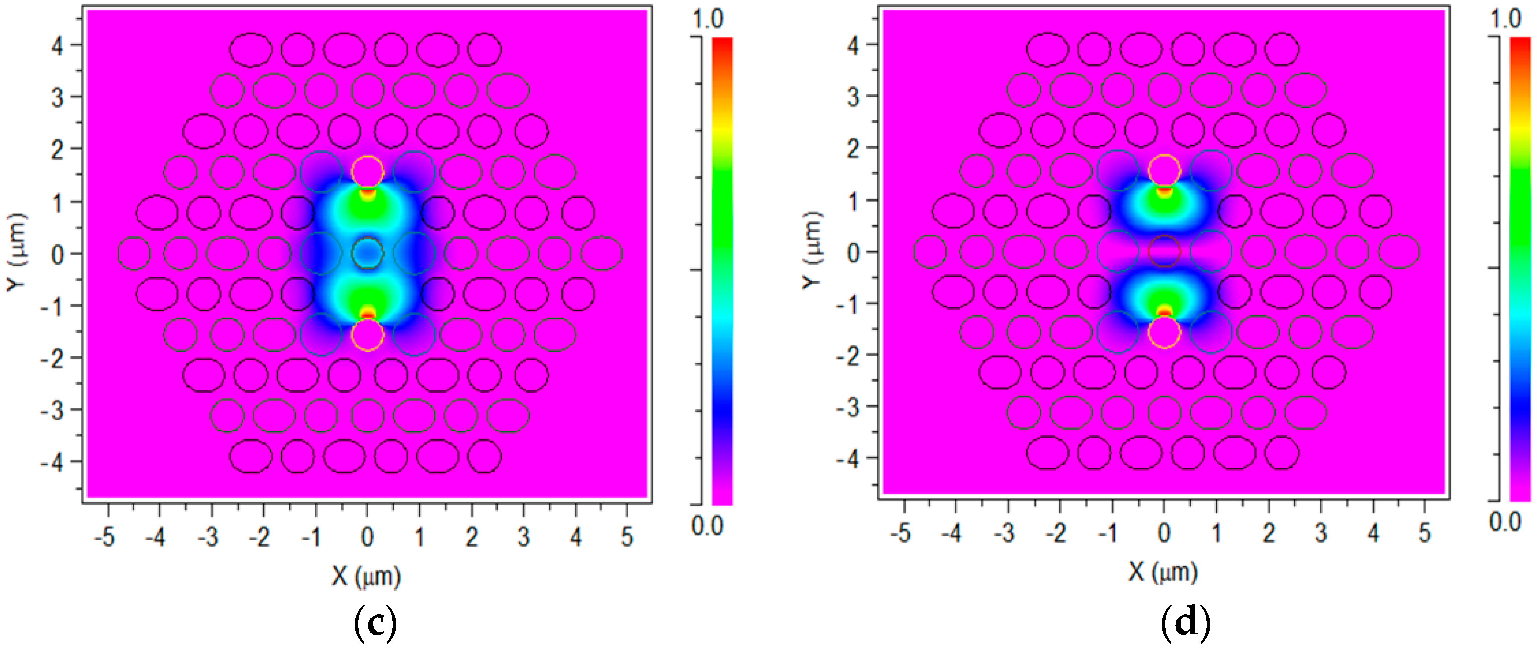
Figure 13.
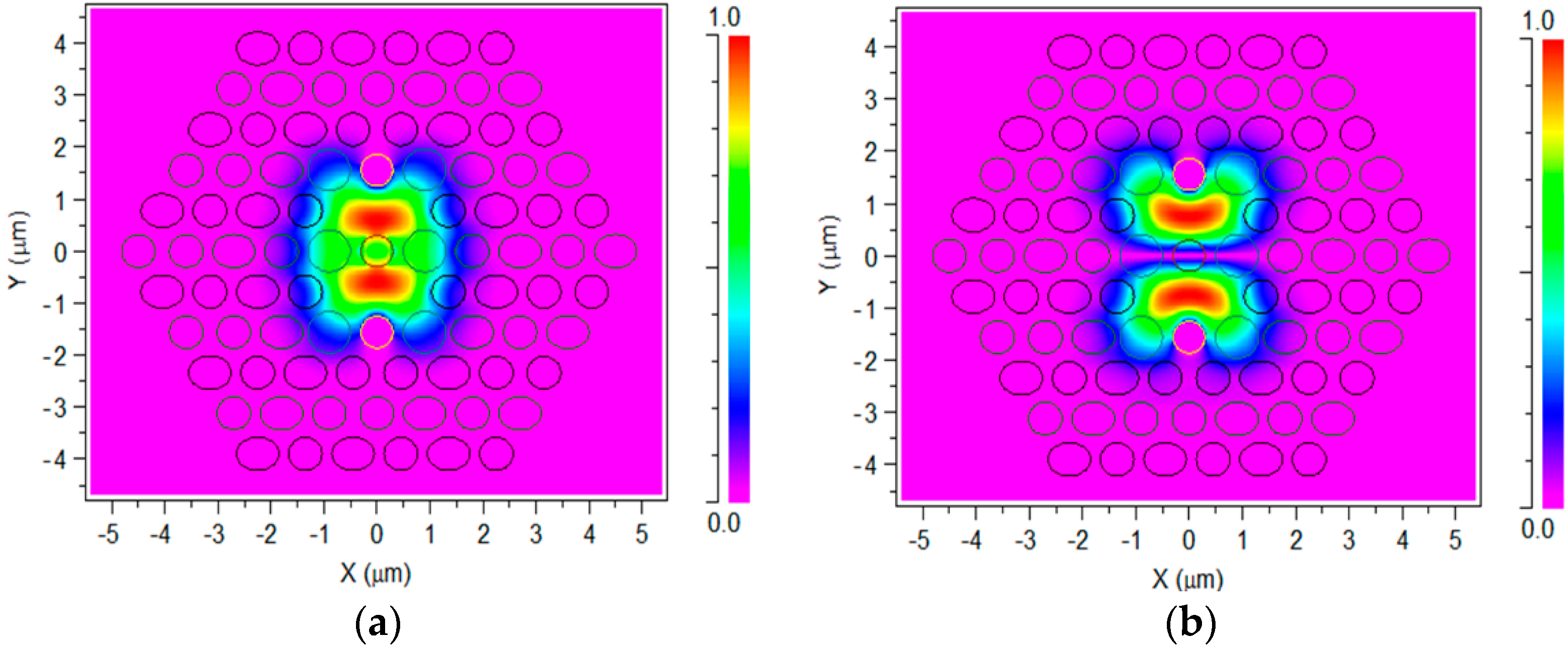
(a) Even-mode of x-direction, (b) odd-mode of x-direction, (c) even-mode of y-direction, and (d) odd-mode of y-direction for PS.
Figure 13.
(a) Even-mode of x-direction, (b) odd-mode of x-direction, (c) even-mode of y-direction, and (d) odd-mode of y-direction for PS.


Table 1.
Comparison of our proposed PS with earlier works.
| References | Length/mm | Bandwidth/dB | Coupling loss/dB |
|---|---|---|---|
| [28] | 1.7 | 40(<−11 dB) | not mentioned |
| [29] | 4.72 | 190(<−20 dB) | not mentioned |
| [30] | 8.7983 | 20(<−20 dB) | 0.02 |
| [31] | 0.249 | 17(<−20 dB) | not mentioned |
| [32] | 0.401 | 140(<−20 dB) | not mentioned |
| [33] | 0.1191 | 249(<−20 dB) | not mentioned |
| [15] | 14.662 | 13(<−10 dB) | not mentioned |
| [34] | 4.036 | 430(<−20 dB) | 0.011 |
| [35] | 0.775 | 32(<−20 dB) | not mentioned |
| Our work | 0.0839 | 32.1(<−10 dB) | 0.0068 |
© 2019 by the authors. Licensee MDPI, Basel, Switzerland. This article is an open access article distributed under the terms and conditions of the Creative Commons Attribution (CC BY) license (http://creativecommons.org/licenses/by/4.0/).
Share and Cite
MDPI and ACS Style
Xu, Q.; Luo, W.; Li, K.; Copner, N.; Lin, S. Design of Polarization Splitter via Liquid and Ti Infiltrated Photonic Crystal Fiber. Crystals 2019, 9, 103. https://0-doi-org.brum.beds.ac.uk/10.3390/cryst9020103
AMA Style
Xu Q, Luo W, Li K, Copner N, Lin S. Design of Polarization Splitter via Liquid and Ti Infiltrated Photonic Crystal Fiber. Crystals. 2019; 9(2):103. https://0-doi-org.brum.beds.ac.uk/10.3390/cryst9020103
Chicago/Turabian StyleXu, Qiang, Wanli Luo, Kang Li, Nigel Copner, and Shebao Lin. 2019. "Design of Polarization Splitter via Liquid and Ti Infiltrated Photonic Crystal Fiber" Crystals 9, no. 2: 103. https://0-doi-org.brum.beds.ac.uk/10.3390/cryst9020103
Note that from the first issue of 2016, this journal uses article numbers instead of page numbers. See further details here.