Article

Numerical Simulation of Thermal-Solutal Capillary-Buoyancy Flow of Ge1–xSix Single Crystals Driven by Surface-Tension and Rotation in a Czochralski Configuration

1
Key Laboratory of Low-grade Energy Utilization Technologies and Systems of Ministry of Education, School of Energy and Power Engineering, Chongqing University, Chongqing 400044, China
2
State Key Laboratory of Mechanical Transmission, Chongqing University, Chongqing 400044, China
*
Author to whom correspondence should be addressed.
Submission received: 18 February 2019 / Revised: 15 April 2019 / Accepted: 20 April 2019 / Published: 22 April 2019
(This article belongs to the Section Crystal Engineering)

Abstract

:
A series of three-dimensional numerical simulations were performed to understand the thermal-solutal capillary-buoyancy flow of Ge1-xSix melts during Czochralski crystal growth with a rotating crystal or crucible. The crystal and crucible rotation Reynolds numbers in this work are 0∼3.5 × 10³ (0∼4.4 rpm) and 0∼−2.4 × 10³ (0∼−1.5 rpm), respectively. Simulation results show that if the thermal capillary Reynolds number is relatively low, the flow will be steady and axisymmetric, even though the crystal or crucible rotates at a constant rate. The critical thermal capillary Reynolds number for the initiation of the three-dimensional oscillatory flow is larger than that of pure fluids. As the crystal or crucible rotation rate increases, the critical thermal capillary Reynolds number first increases and then decreases. The dominant flow pattern after the flow destabilization is azimuthal traveling waves. Furthermore, a reversed evolution from the oscillatory spoke pattern to traveling waves appears in the melt. Once the crystal or crucible rotation rate is relatively large, the traveling waves respectively evolve to rotating waves at the crystal rotation and a spindle-like pattern at the crucible rotation. In addition, the maximum amplitude of solute concentration oscillation on the free surface initially decreases, but finally rises with the crystal or crucible rotation rate increasing.

1. Introduction

Single crystals of oxides and semiconductors mostly grow from melt, which takes on an important role in microelectronic and optoelectronic devices [1]. More than 80% of single crystals are grown by the Czochralski (Cz) method [2]. This method is particularly successful for the growth of germanium (Ge), silicon (Si), gallium-arsenide (Ga1–xAsx), germanium-silicon (Ge1–x Six) and so on. Here, x is the mass fraction of arsenide or silicon.
A classical Cz crystal growth system consists of four important parts, crucible, crystal, melt, and heater. The crucible is heated by a heater to keep the materials in molten state. The crystal is kept in a lower temperature and placed so as to contact the surface of the melt. The crystal and crucible are usually rotated to improve the uniformity of thermal distribution and get a high quality of single crystals. Several forces, including surface tension, buoyancy, Coriolis, and centrifugal forces interact with each other on different scales through the crystal growth process, which makes the process difficult to characterize and control [3,4]. Due to the interaction between aforementioned forces, different flow instabilities always occur and significantly affect the transport process in the melt [3,4,5,6]. This transport process, in turn, considerably affects the quality of single crystals. Therefore, there is an urgent demand to fully understand flow phenomena in melts during the Cz crystal growth process.
The thermal capillary effect generated by the temperature difference between the crystal and the crucible during the Cz crystal growth process, as well as the buoyancy, have great effects on the flow field. Galazka and Wilke [7] numerically predicted that the coupling action of thermal capillary and buoyancy forces leads to the interface being much more convex to the melt, compared to the results without the thermal capillary flow. Schwabe [8] carried out experiments on the thermal capillary flow in a Cz configuration with various gravities. The thermal capillary flow penetrates fully into the liquid pool under conditions of microgravity, whereas it separates into a layer-like flow close to the free surface on the earth. Li et al. [9,10] studied the flow bifurcation of the thermal capillary flow in a shallow molten silicon pool. They observed that the steady two-dimensional (2D) flow bifurcates to a steady three-dimensional (3D) flow, and then evolves to a 3D oscillatory flow as the thermal capillary Reynolds number rises. However, a steady 2D flow is directly invaded by a 3D oscillatory flow in a deep pool filled with molten silicon. Subsequently, Shen et al. [11,12] observed the flow patterns and the transitions of the thermocapillary-buoyancy flow of a pure fluid in a Cz configuration with rotating crystal and crucible.
The solute/impurity concentration shows an uneven distribution, generated by segregation during the Cz crystal growth process, which induces the solutal capillary force and the solutal buoyancy force in the melts [13,14,15]. It is obvious that the coupling effect of various driving forces makes the melt flow become much more complex. Bergman [16] first reported that, even if the solutal and thermal capillary forces are equal but opposite due to horizontal solute concentration and temperature gradients, the thermal-solutal capillary flow can be observed in the absence of a buoyancy force, because of the difference between mass and thermal diffusivities. Soon after, Chen et al. [17,18] systematically investigated flow instability with different Prandtl (Pr) numbers, Lewis (Le) numbers, and aspect ratios by 3D numerical simulations. Kamotani et al. [19] reported complex flow patterns and the bifurcations of the thermal-solutal capillary-buoyancy convection at different buoyancy ratios. If the buoyancy ratio is relatively small, a unicellular flow pattern, accompanied by secondary cells, was observed. However, a three-layered pattern with secondary cells appears with a large buoyancy ratio. Arafune et al. [20,21] observed that the classical surface velocities in solutal capillary flows are about 3–5 times larger than those in thermal capillary flows.
Recently, thermal-solutal capillary-buoyancy flows in annular pools have attracted much more attention. The annular pool is a classic simplified model of a Cz configuration. Firstly, Li et al. [22] conducted 2D simulations to study the thermal-solutal capillary-buoyancy flow of binary mixtures. They found that the development from a steady flow to an oscillatory flow experiences a typical Hopf bifurcation. Due to the limit of a 2D geometric model in the azimuthal direction, Yu et al. [23,24,25] pursued a similar direction by conducting experiments and 3D numerical simulations. They reported that the solutal capillary and buoyancy forces, which are generated by the solute gradient as a result of the Soret effect, promote the destabilization of the thermal-solutal capillary-buoyancy flow in binary mixtures. However, they have almost no impact on flow patterns and their transition. It is surprising that the thermal-solutal capillary-buoyancy flow can always be observed, even if the solutal and thermal capillary effects are equal but opposite. The critical thermal Reynolds number for the generation of a 3D flow decreases with the aspect ratio of the annular pool. However, it increases alongside the increase of the capillary ratio. Flow patterns strongly depend on the capillary ratio, aspect ratio, and thermal capillary Reynolds number.
Although annular pools can fulfill fundamental requirements for the study of flow instability during the crystal growth process, it still has some limitations, such as the lack of the crystal face touching the melt free surface, its inability to realize crystal and crucible rotations and so on. Therefore, it is necessary to explore thermal-solutal capillary-buoyancy flow in a Cz configuration. Abbasoglu and Sezai [26] reported that the approximate range of capillary ratios in a Ge1-xSix melt, due to the segregation during Cz crystal growth, varies from −2.44 to −0.20. In addition, the radial solute concentration difference decreases along the rising of the aspect ratio and radial temperature difference. This is because the strong flow suppresses the solute concentration difference. Unfortunately, the rotations of crystals and crucibles were not taken into consideration, which is an essential industrial practice for improving the quality of crystals in the Cz crystal growth process. A lot of previous works focusing on the melt flow and the flow instability have not yet paid attention to solute diffusion in binary alloys [27,28,29,30].
Therefore, it is indispensable to carry out numerical simulations to precisely understand the influences of rotating crystals and crucibles on the thermal-solutal capillary-buoyancy convections in a Cz configuration. The present work is beneficial for improving crystal qualities in Cz crystal growth.

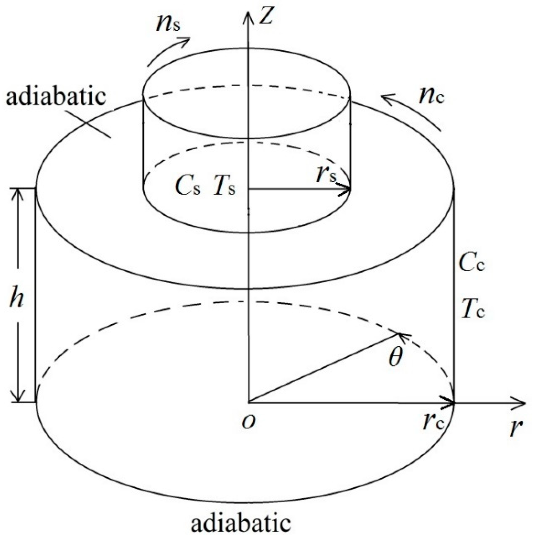
2. Physical and Mathematical Model

2.1. Basic Assumptions and Governing Equations

Figure 1 gives the physical model, which is a classical simplified model of the Cz growth system [31,32,33]. A disc with the radius of rs = 23 mm contacts the free surface of Ge1–xSix melt. The Ge1–xSix melt is in a cylindrical crucible with the radius of rc = 46 mm (hereafter are respectively called as “crystal” and “crucible”). The crystal and crucible rotate at constant rates ns and nc. The melt/crystal interface and sidewall of the crucible are maintained at constant temperatures and solute concentrations are Ts, Cs, Tc, and Cc, where Ts = Tm < Tc and Cs < Cc. Tm = 1271.3 K, is the melting point of the Ge1–xSix melt. The depth of the Ge1–xSix melt is h. Furthermore, the Ge1–xSix melt is considered as an incompressible Newtonian fluid with constant properties, except for the surface tension and density in the buoyancy term of the momentum equation. The flow is laminar. The melt/crystal interface and free surface are non-deformable and flat, where the solute and thermal capillary forces are considered. A no-slip condition is adopted in all solid-liquid boundaries. In addition, the free surface and crucible bottom are assumed to be impermeable and adiabatic.
The surface tension and density are linear functions of temperature and solute concentration, respectively, which are defined as
σ ( T , C ) = σ 0 γ T ( T T 0 ) γ C ( C C 0 )
ρ ( T , C ) = ρ 0 [ 1 β T ( T T 0 ) β C ( C C 0 ) ]
where γT = −(∂σ/∂T)C,γC = −(∂σ/∂C)T, βT = −(∂ρ/∂T)C,βC = −(∂ρ/∂C)T. Here, T0 and C0 are the reference temperature and solute concentration, respectively.
Using rc, rc2/ν, ν/rc, and μν /rc2 as the scale quantities for length, time, velocity, and pressure, the governing equations are expressed by following dimensionless forms,
V = 0
V τ + V V = P + 2 V + G r T ( Θ + R ρ Φ ) e Z
Θ τ + V Θ = 1 P r 2 Θ
Φ τ + V Φ = 1 L e P r 2 Φ
where V (U, V, W) is the dimensionless velocity vector and eZ is the unit vector in the Z direction. P, τ, Θ = (TTs)/(TcTs), and Φ = (CCs)/(CcCs) are the dimensionless dynamic pressure, time, temperature, and solute concentration, respectively. Rρ = βCΔC/(βTΔT), GrT = TΔT(ro-ri)3/ν2, Pr = ν/α, and Le = α/D are the ratio of the solute to thermal buoyancy forces, the thermal Grashoff number, Prandtl number, and Lewis number. Where ΔT = TcTs and ΔC = CcCs. Thus, the last term in Equation (4) shows the buoyancy effect. In addition, D, a, ν, and μ are the mass diffusivity of the silicon, thermal diffusivity, kinematic viscosity, and dynamic viscosity.
Based on these assumptions, the boundary conditions can be expressed as follows.
At the free surface
R s   <   R <   R c , 0 < θ 2 π ,   Z   =   Г
W = 0 , U Z = R e T Θ R R e C Φ R
V Z = R e T Θ R θ R e C Φ R θ
Θ Z = Φ Z = 0
Here, Г is the aspect ratio, which is defined as Г = H/Rc. ReT and Rec are the thermal and solutal capillary Reynolds numbers. They are respectively defined as
R e T = γ T r c ( T c T s ) ν μ , R e C = γ C r c ( C c C s ) ν μ
The ratio between the solutal and thermal capillary effects is denoted as the capillary ratio Rσ, which is defined as:
R σ = R e C R e T = γ C Δ C γ T Δ T
At the bottom (0 < R < Rc, 0 < θ 2 π , Z = 0)
U = W = 0 , V = R e c R ,   Θ Z = Φ Z = 0
Rec is the crucible rotation Reynolds number, which is expressed as
R e c = 2 π n c r c 2 60 ν
At the melt/crystal interface (RRs, 0 < θ 2 π , Z = Г)
U = W = 0 , V = R e s R R s ,   Θ = Φ = 0
Here, Res is the crystal rotation Reynolds number, which is defined as
R e s = 2 π r s n s r c 60 ν
At the sidewall of the crucible (R = Rc, 0 θ 2 π , 0 Z Γ )
U = W = 0 ,   V = R e c ,   Θ = Φ = 1
The initial conditions ( τ = 0 )
U = W = V = 0
Θ = Φ = 0 ( R R s )
Θ = Φ = ln ( R / R s ) / ln ( R c / R s ) ,   ( R s   <   R <   1 )

2.2. Calculations’ Conditions and Numerical Method

The radius ratio and aspect ratio of the Cz configuration are fixed at Rs = Г = 0.5. The Ge1−xSix melt is chosen as the working fluid. Its initial mass fraction of silicon is 1.99% (x = 1.99%), which corresponds to the molar fraction of 5%. This mass fraction agrees well with the mean solute concentration in the melt, due to segregation during Cz crystal growth [26,34]. The physical properties of the Ge1–xSix melt at 1271.3 K are shown in Table 1 [26,34]. As reported in Reference [26], the approximate range of capillary ratios in the GexSi1–x melt due to segregation during Cz crystal growth is from −2.44 to −0.20. Therefore, Rσ is fixed at −0.8, which ensures that much more attention is paid to the influence of the rotating crystal and crucible on the thermal-solutal capillary-buoyancy flow. The crystal and crucible rotation Reynolds numbers range from 0 to 3.5 × 10³ and −2.4 × 10³. The thermal capillary Reynolds number ranges from 0 to 4 × 10⁴.
The governing equations are handled by the finite volume method (FVM). The QUICK scheme is applied for the convective terms. The second order central-difference approximation is introduced for the diffusion terms. Meanwhile, the SIMPLEC algorithm is adopted to deal with the coupling between the velocity and pressure. The dimensionless time step is from 1.2 × 10⁻⁵ to 1.1 × 10⁻⁴. When the largest relative error of these governing equations in the computational domain gets below 10−5 at each time step, the solution is taken for converging.
In order to verify the grid convergence, simulations on the thermal-solutal capillary-buoyancy flow of Ge1–xSix melt with three different meshes at Rec = 9.4 × 10², Res = −1.2 × 10³, and ReT = 2 × 10⁴ were conducted. Table 2 gives the corresponding wave numbers and oscillation frequencies. It is obvious that the 62R × 50Z × 80θ grid is a suitable choice for accurate simulations in this work.
In order to validate the numerical method, simulations on the double-diffusive capillary convection in rectangular cavities were conducted at the same conditions with Refs. [17,35]. Results show that the maximum deviations of the Nusselt number and oscillation frequency are 1.1% [35] and 1.5% [17], respectively, as listed in Table 3 and Table 4. In addition, the present numerical method was also checked by experiments. The results from the numerical simulations agree well with those from the experiments [23]. Therefore, the thermal-solutal capillary-buoyancy flow can be solved well by the present numerical method.

3. Results and Discussion
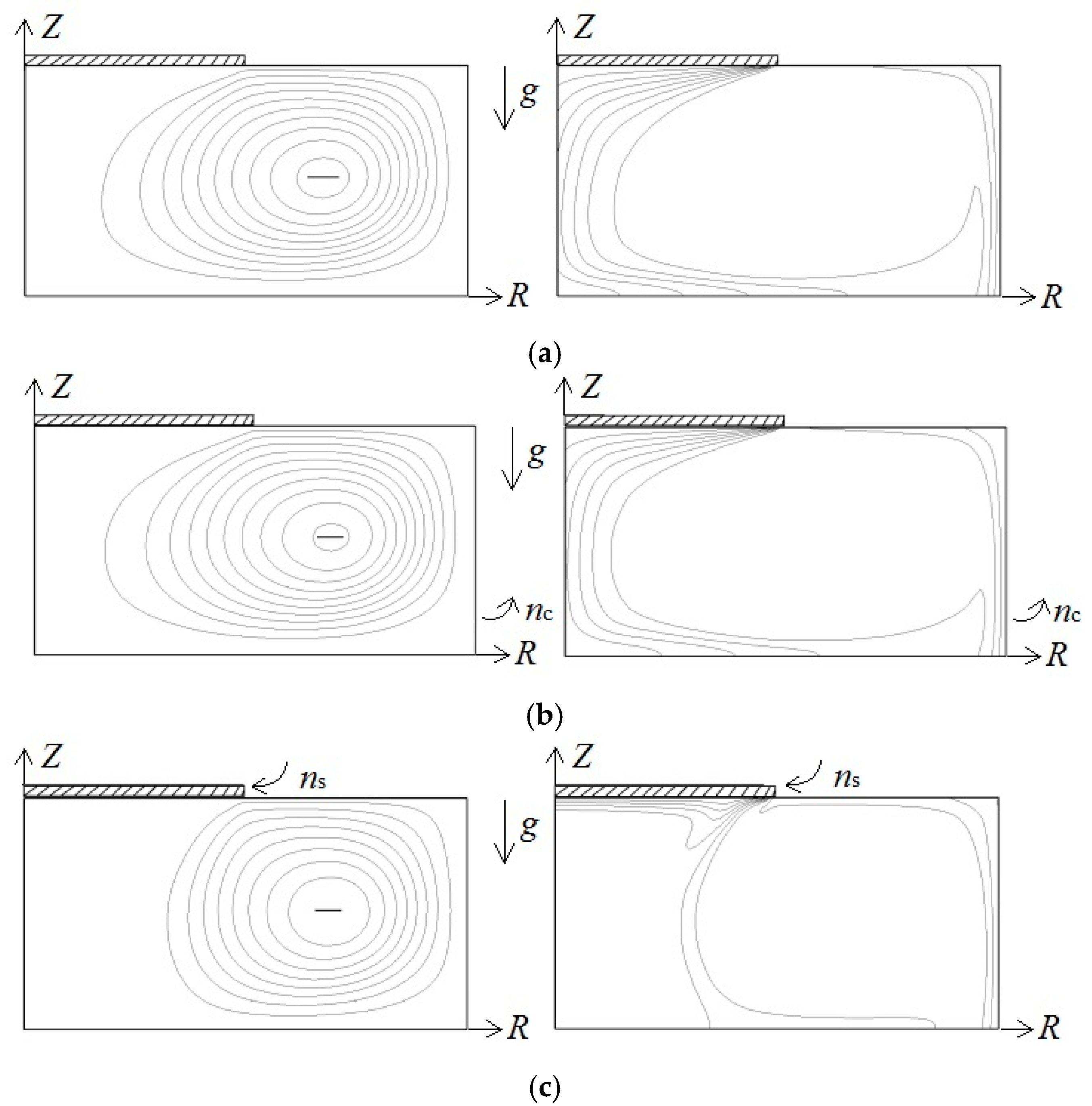
3.1. Basic Flow

When the thermal capillary Reynolds number is relatively low, the flow is axisymmetric and steady, even though the crystal and crucible rotate at constant values. The steady axisymmetric flow is an ideal flow condition for the Cz growth process, due to its thermal and crystal uniformities. This typical flow was also reported in binary mixtures or pure fluids in a crystal or crucible rotating system, which is usually called “basic flow” [36,37,38]. The dimensionless stream function ψ is applied to show the flow field and defined as
U = 1 R ψ Z , W = 1 R ψ R
Figure 2 shows the streamlines and iso-concentration lines at ReT = 2 × 10³ with different rotation Reynolds numbers. When Rec = Res = 0, the flow is only moved by the buoyancy and capillary forces. When the capillary ratio is fixed at −0.8, the thermal capillary force is dominant, which induces flow movement from the crucible sidewall to the crystal edge along the free surface, as displayed in Figure 2a. The iso-concentration lines mainly concentrate near the crucible sidewall and below the crystal. Once the crucible rotates, for example, at Rec = 46.8 and Res = 0, the flow is slightly suppressed. The maximum stream function of the basic flow decreases from 16.4 to 16.1. However, the streamlines and iso-concentration lines have slight changes, as shown in Figure 2b. When only the crystal rotates, at Rec = 0 and Res = −467.5, the melt near the crystal rotates along with the crystal. In addition, the maximum stream function decreases from 16.4 to 15.8 (see Figure 2c). It implies that the flow strength is slightly weakened by the rotation.

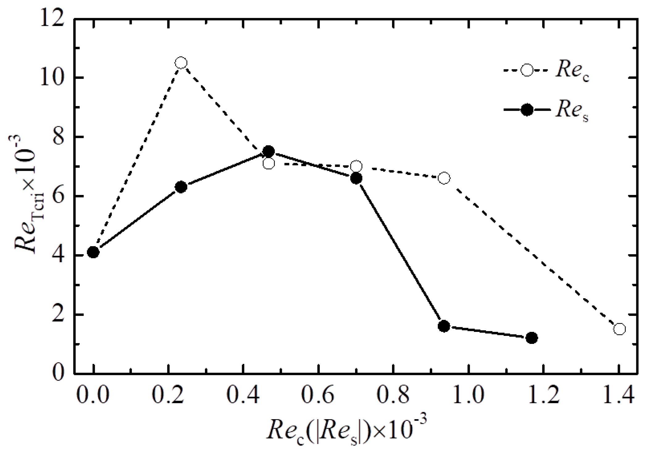
3.2. Critical Conditions for the Flow Destabilization

As the thermal capillary Reynolds number increases, the basic flow is clearly enhanced. Once the thermal capillary Reynolds number is over a threshold value, the basic flow rapidly destabilizes and then bifurcates into a 3D oscillatory flow. Figure 3 gives the variations of critical thermal capillary Reynolds numbers along the crystal or crucible rotation Reynolds number. This dichotomy is successfully applied for obtaining the critical thermal capillary Reynolds numbers [24,25], and maximum deviation is controlled below 100. The critical thermal capillary Reynolds number at a non-rotation Cz configuration is 4.1 × 10³, which is much larger than that of pure fluids [9,10]. This discrepancy is because of the opposite directions of the thermal and solutal capillary forces at Rσ = −0.8 [25]. Thus, the quality of a pure component crystal is much more essential to the temperature difference between the crystal and crucible than that of a compound.
The critical thermal capillary Reynolds number rises first, and then reduces along the crystal or crucible rotation rate. When Rσ = −0.8, the thermal capillary effect plays a dominant role on the flow. The melt on the free surface moves from the crucible sidewall to crystal edge. Once the crystal rotates only at a relatively low rate, the centrifugal force suppresses the surface melt flow. Therefore, the crystal rotation enhances the flow stability until |Res| = 470, which is also reported in pure fluids [9,39] or binary mixtures [37]. With the crystal rotation rate increasing, a clockwise rotating cell under the crystal is formed for the crystal rotation, which shears with a counter-clockwise rotating cell, driven by the coupling action between the thermal and solutal capillary effects. Thus, the fluctuation of the melt flow is enhanced, while the flow stability is weakened, as displayed in Figure 3.
At Rec ≤ 230 and Res = 0, almost all melt moves azimuthally with the crucible, which leads to the melt flow being much more uniform and more stable [36]. As the crucible rotation Reynolds number rises, the disturbance formed by the rotation is enhanced, which promotes the steady flow towards bifurcating to a 3D oscillatory flow. Thus, the critical thermal capillary Reynolds number initially grows, and then decreases, alongside the crucible rotation Reynolds number rising. When the crystal or crucible rotation rate is smaller than a certain value, the rotation benefits the quality of a crystal. However, the crystal or crucible rotation can have negative effects on the quality of a crystal at a larger rotation rate. Once the crystal and crucible rotation Reynolds numbers respectively exceed about 1.2 × 10³ and 1.4 × 10³, the 3D oscillatory flow is dominated by the crystal or crucible rotation. Furthermore, the flow is almost independent of the thermal Reynolds number [11,36].

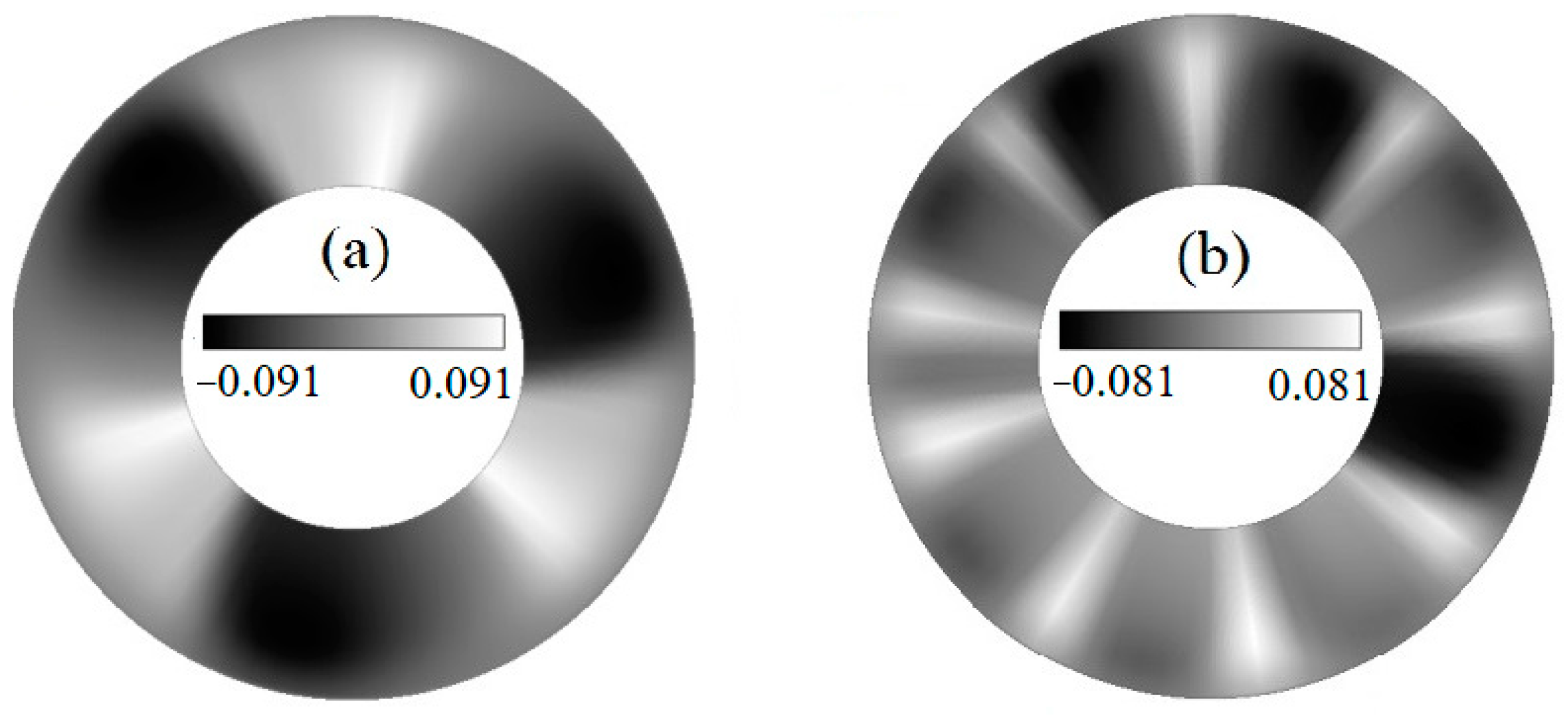
3.3. Characteristics of the 3D Oscillatory Flow

The fluctuation δX of physical quantity X is usually used to extract the spatial disturbance characteristics,
δ X ( R , θ , Z , τ ) = X ( R , θ , Z , τ ) 1 2 π 0 2 π X ( R , θ , Z , τ ) d θ
It should be pointed out that X is the dimensionless velocity, solute concentration, or temperature. Since the Schmidt number is much greater than the Prandtl number of a Ge1–xSix melt, the solute concentration fluctuation attracts more attention here. Figure 4 gives the overview of surface solute concentration fluctuations of 3D oscillatory flows in a non-rotation Cz system. The flow pattern in Figure 4 looks like spokes of a wheel. It was named the “spoke pattern” in Reference [40]. The spoke pattern, with three traveling waves along a clockwise direction, is observed at ReT = 5 × 10³, as shown in Figure 4a. The wave number m is obtained from the bright and dark spokes. This flow pattern does not appear in pure fluids [9]. In pure fluids, the thermal capillary and buoyancy are the only driving forces. However, in a Ge1–xSix melt, there is a nonuniform solute concentration distribution along the axial direction, close to the free surface. This unique solute concentration distribution in Ge1–xSix melts will result in the Rayleigh-Marangoni-Benard instability.
The wave number of spoke pattern increases as the thermal capillary Reynolds number increases. For example, once the thermal capillary Reynolds number grows from 5 × 10³ to 104, the wave number increases from 3 to 9. Furthermore, the azimuthal traveling spoke pattern transits to an oscillatory spoke pattern. The distribution of spokes on the free surface becomes nonuniform. The enhanced buoyancy-driven flow, due to the nonuniform solute concentration distribution in the axial direction, carries a lot of Ge1–xSix melt from the crucible bottom to the free surface, close to the sidewall at a large thermal capillary Reynolds number. Thus, the oscillatory spoke pattern swings in the azimuthal direction and merges, which is reported in Reference [24]. On the other hand, the amplitude of the surface solute concentration fluctuation decreases slightly, because of the increase of the wave number.

3.3.1. The Influences of Crystal Rotation

Figure 5 shows the effects of the crystal rotation on 3D oscillatory flow at Rec = 0 and ReT = 104. When the crystal rotates at Res = −4.7 × 10², the oscillatory spoke pattern (see Figure 4b) develops to the azimuthal traveling spoke pattern with three waves, as shown in Figure 5a. The traveling waves at Rec = 0, Res = −4.7 × 10² and ReT = 104 are the same, with the flow pattern at ReT = 5 × 10³ in a non-rotation Cz system. As reported in Ref. [25], the capillary effect is a key factor of flow destabilization for the binary mixtures at −0.8 ≤ Rσ ≤ −0.2. Compared with the flow transition in a non-rotation Cz system, a reversed evolution from the oscillatory spoke pattern to traveling waves is observed when the crystal rotation rate increases. Thus, the crystal at a relatively low rotation rate plays a suppression effect on the flow instability. When Res = −1.8 × 10³, the traveling waves are disturbed by the rotating waves, which is induced by centrifugal force instability [11,12], as displayed in Figure 5b. The traveling waves still take a dominant role, while the rotating waves will affect the traveling waves. The wave number reduces from 3 to 2. Meanwhile, the traveling waves begin to exhibit disorder, especially in the region close to the crucible sidewall. The rotating waves are further enhanced with the increased crystal rotation rate. The rotating waves are observed near the crucible sidewall (see Figure 5c).
Figure 6 gives the time dependence of azimuthal velocity at the monitoring point P (R = 0.75, Z = 0.5, θ = 0). At Rec = 0, Res = −1.8 × 10³, and ReT = 104, the azimuthal velocity appears as quasi-periodical variation with a period of 0.1, as shown in Figure 6a, which means that the traveling wave shows a quasi-periodic oscillatory flow. If the crystal rotation Reynolds number increases to 2.3 × 10³, the average amplitude of azimuthal velocity rapidly increases, while its periodicity diminishes, as displayed in Figure 6b. When the crystal rotation Reynolds number rises from 1.8 × 10³ to 2.3 × 10³, the rotating waves are enhanced significantly, as shown in Figure 5b,c. Meanwhile, the traveling waves lose the dominant position and then compete with the rotating waves. The flow loses its periodicity, since the competition between the traveling waves and rotating waves becomes fiercer alongside the crystal rotation Reynolds number increasing. Thus, the maximum azimuthal velocity is not observed at the crystal rotation Reynolds number of 2.3 × 10³ (see Figure 6b). Figure 7 shows that the maximum amplitude of solute concentration fluctuation initially decreases, but finally increases as the crystal rotation rate grows. If the crystal rotation rate is relatively low, the capillary effect plays a leading role. Meanwhile, the crystal rotation suppresses the flow instability generated by the capillary effect. Thus, the amplitude of solute concentration fluctuation reduces with the rise of the crystal rotation rate. The rotating waves are dominant when the crystal rotates at a large rate. The centrifugal force instability related to the rotation results in the increase of the amplitude of the solute concentration fluctuation along the crystal rotation.

3.3.2. The Influence of Crucible Rotation

Once the crucible rotates, the oscillatory spoke pattern also converts to traveling waves, as shown in Figure 8. Here, the traveling waves are mainly located close to the crystal. This flow bifurcation with the crucible rotation is same as that with the crystal rotation (compare Figure 5 and Figure 8). Thus, the crucible rotation with a low rotation rate also has a suppression effect on flow instability. Figure 9 gives the streamlines and iso-concentration lines of 3D oscillation flow at the R-Z plane of θ = 0 when Res = 0, Rec = 9.4 × 10² and ReT = 1.4 × 10⁴. Two counter-clockwise rotating cells are observed. These two rotating cells are the result of the coupling action of the thermal and solutal capillary effects. This has also been reported in non-rotating annular pools [25]. Due to the suppression role of the crucible rotation, the other one close to the crucible sidewall is weakened. Therefore, the oscillations of the solute concentration close to the crucible sidewall are much smaller than those near the crystal. The wave number m rises from 3 to 4 as the crucible rotation Reynolds number is raised from 9.4 × 10² to 1.4 × 10³. In addition, the traveling waves gradually extend to the sidewall. If the crucible rotates at a large rate, the traveling waves develop a spindle-like pattern, as displayed in Figure 8c. As reported in Refs. [11,12], the spindle-like pattern should be a result of the circular shear instability.
Figure 10 gives the variations of the maximum amplitude of solute concentration fluctuation along the crucible rotation Reynolds number. Obviously, the tendency of the maximum amplitude of solute concentration fluctuation with the crucible rotation is similar to that of the crystal rotation. Specifically, the maximum amplitude of solute concentration fluctuation first decreases, then increases with the growth of the crucible rotation Reynolds number. The crucible rotation effectively suppresses the solute fluctuation of traveling waves at first. After that, the flow is gradually affected by the circular shear instability. Thus, the maximum amplitude of solute concentration fluctuation rises with the crucible rotation.

4. Conclusions

3D numerical simulations were performed to investigate the influence of a rotating crystal and crucible on the thermal-solutal capillary-buoyancy flow of a Ge1–xSix melt in a Cz configuration. The critical condition for the initiation of a 3D oscillation flow was obtained, and the mechanism of flow destabilization was analyzed. Meanwhile, the basic characteristics of steady and 3D oscillatory flows were discussed. This work contributes to the development of the Cz crystal growth method. Based on these above results, some conclusions are drawn as follows.
1. If the thermal capillary Reynolds number is relatively low, the flow appears as a steady axisymmetric flow, even though the crystal and crucible rotate at constant values. A steady axisymmetric flow is an ideal flow condition for the Cz growth process, due to its good thermal and crystal uniformity. This steady axisymmetric flow is suppressed by the crystal or crucible rotation. The strength of the steady axisymmetric flow exists as a decreasing trend as the crystal or crucible rotation rate increases.
2. The critical thermal capillary Reynolds numbers for the onset of a 3D oscillatory flow in a Cz configuration are much greater than those of pure fluids. Furthermore, the critical thermal capillary Reynolds number first rises, and then falls as the crystal or crucible rotation rate increases. Clearly, the quality of a pure component crystal is much more essential to the temperature difference than that of a compound. If the crystal or crucible rotation rate is smaller than a certain value, the rotation benefits the quality of a crystal. However, the crystal or crucible rotation can have negative effects on the quality of a crystal at a large rotation rate.
3. Due to the suppression effect of the crystal or crucible rotation at a low rotation rate, a reversed evolution from an oscillatory spoke pattern to traveling waves is found as the crystal or crucible rotation rate increases. Once the crystal or crucible rotates at a large rate, the traveling waves transition to rotating waves in a crystal rotation system and a spindle-like pattern in a crucible rotation system. In addition, the maximum amplitude of the solute concentration fluctuation of the 3D oscillation flow initially decreases, but finally increases alongside the growth of the crystal or crucible rotation rate.

Author Contributions

J.-J.Y. supervised the research and drafted the manuscript. L.Z. (Lu Zhang), T.S., and L.Z. (Li Zhang) finished the simulation and data curation work. Y.-R.L. proposed the methodology.

Funding

This work was supported by National Natural Science Foundation of China (Grant Nos. 51776022, 51806025), Chongqing University Postgraduates’ Innovation Project (Grant No. CYS18041), China Postdoctoral Science Foundation (Grant No. 2017M622961), and the Fundamental Research Funds for the Central Universities (No. 2018CDXYDL0001).

Acknowledgments

The authors thank Yimin Ding from Pennsylvania State University for helpful grammatical edits.

Conflicts of Interest

The authors declare no conflict of interest.

References

  1. Sekhon, M.; Lent, B.; Ma, Y.B. Numerical analysis of the combined influence of accelerated crucible rotation and dynamic crucible translation on liquid phase diffusion growth of SiGe. Crystals 2016, 6, 116. [Google Scholar] [CrossRef]
  2. Jana, S.; Dost, S.; Kumar, V.; Durst, F. A numerical simulation study for the Czochralski growth process of Si under magnetic field. Int. J. Eng. Sci. 2006, 44, 554–573. [Google Scholar] [CrossRef]
  3. Hu, C.; Chen, J.C.; Nguyen, T.H.T.; Hou, Z.Z.; Chen, C.H.; Huang, Y.H.; Yang, M. Optimization of heat transfer during the directional solification process of 1600 kg silicon feedstock. Crystals 2018, 484, 70–77. [Google Scholar]
  4. Kumar, V.; Basu, B.; Enger, S.; Brenner, G.; Durst, F. Role of Marangoni convection in Si-Czochralski melts—Part II: 3D predictions with crystal rotation. J. Cryst. Growth 2003, 255, 27–39. [Google Scholar] [CrossRef]
  5. Yamamoto, T.; Okano, Y.; Ujihara, T.; Dost, S. Global simulation of the induction heating TSSG process of SiC for the effects of Marangoni convection, free surface deformation and seed rotation. J. Cryst. Growth 2017, 470, 75–88. [Google Scholar] [CrossRef]
  6. Derby, J.J. Fluid dynamics in crystal growth: The good, the bad, and the ugly. Prog. Cryst. Growth Charact. Mater. 2016, 2, 286–301. [Google Scholar] [CrossRef]
  7. Gałązka, Z.; Wilke, H. Influence of Marangoni convection on the flow pattern in the melt during growth of Y3Al5O12 single crystals by the Czochralski method. J. Cryst. Growth 2000, 216, 389–398. [Google Scholar] [CrossRef]
  8. Schwabe, D. Buoyant-thermocapillary and pure thermocapillary convective instabilities in Czochralski systems. J. Cryst. Growth 2002, 237, 1849–1853. [Google Scholar] [CrossRef]
  9. Li, Y.R.; Quan, X.J.; Peng, L.; Imaishi, N.; Wu, S.Y.; Zeng, D.L. Three-dimensional thermocapillary-buoyancy flow in a shallow molten silicon pool with Cz configuration. Int. J. Heat Mass Transf. 2005, 48, 1952–1960. [Google Scholar] [CrossRef]
  10. Li, Y.R.; Imaishi, N.L.; Peng, S.Y.; Wu, T.; Hibiya. Thermocapillary flow in a shallow molten silicon pool with Czochralski configuration. J. Cryst. Growth 2004, 266, 88–95. [Google Scholar] [CrossRef]
  11. Shen, T.; Wu, C.M.; Li, Y.R. Experimental investigation on the effect of crystal and crucible rotation on thermocapillary convection in a Czochralski configuration. Int. J. Therm. Sci. 2016, 104, 20–28. [Google Scholar] [CrossRef]
  12. Shen, T.; Wu, C.M.; Zhang, L.; Li, Y.R. Experimental investigation on effects of crystal and crucible rotation on thermal convection in a model Czochralski configuration. J. Cryst. Growth 2016, 438, 55–62. [Google Scholar] [CrossRef]
  13. Yonenaga, I.; Murakami, Y. Segregation during the seeding process in the Czochralski growth of GeSi alloys. J. Cryst. Growth 1998, 191, 399–404. [Google Scholar] [CrossRef]
  14. Yonenaga, I. Czochralski growth of GeSi bulk alloy crystals. J. Cryst. Growth 1999, 198, 404–408. [Google Scholar] [CrossRef]
  15. Niu, X.H.; Zhang, W.L.; Lu, G.Q.; Jiang, Z.W. Distribution of Ge in high concentration Ge-doped Czochralski-Si crystal. J. Cryst. Growth 2004, 267, 424–428. [Google Scholar] [CrossRef]
  16. Bergman, T.L. Numerical simulation of double-diffusive Marangoni convection. Phys. Fluids 1986, 29, 2103–2108. [Google Scholar] [CrossRef]
  17. Chen, Z.W.; Li, Y.S.; Zhan, J.M. Double-diffusive Marangoni convection in a rectangular cavity: Onset of convection. Phys. Fluids 2010, 22, 034106. [Google Scholar] [CrossRef] [Green Version]
  18. Li, Y.S.; Chen, Z.W.; Zhan, J.M. Double-diffusive Marangoni convection in a rectangular cavity: Transition to chaos. Int. J. Heat Mass Transf. 2010, 53, 5223–5231. [Google Scholar] [CrossRef]
  19. Kamotani, Y.; Wang, L.W.; Ostrach, S.; Jiang, H.D. Experimental study of natural convection in shallow enclosures with horizontal temperature and concentration gradients. Int. J. Heat Mass Transf. 1985, 28, 165–173. [Google Scholar] [CrossRef]
  20. Arafune, K.; Hirata, A. Interactive solutal and thermal Marangoni convection in a rectangular open boat. Numer. Heat Tranf. A Appl. 1998, 34, 421–429. [Google Scholar] [CrossRef]
  21. Arafune, K.; Hirata, A. Thermal and solutal Marangoni convection in In-Ga-Sb system. J. Cryst. Growth 1999, 197, 811–817. [Google Scholar] [CrossRef]
  22. Li, Y.R.; Zhou, Y.L.; Tang, J.W.; Gong, Z.X. Two-dimensional numerical simulation for flow pattern transition of thermal-solutal capillary convection in an annular pool. Microgravity Sci. Technol. 2013, 25, 225–230. [Google Scholar] [CrossRef]
  23. Yu, J.J.; Li, Y.R.; Wu, C.M.; Chen, J.C. Three-dimensional thermocapillary–buoyancy flow of a binary mixture with Soret effect in a shallow annular pool. Int. J. Heat Mass Transf. 2015, 90, 1071–1081. [Google Scholar] [CrossRef]
  24. Yu, J.J.; Wu, C.M.; Li, Y.R.; Chen, J.C. Thermal-solutal capillary-buoyancy flow of a low Prandtl number binary mixture with a −1 capillary ratio in an annular pool. Phys. Fluids 2016, 28, 084102. [Google Scholar] [CrossRef]
  25. Yu, J.J.; Li, Y.R.; Chen, J.C.; Zhang, Y.; Wu, C.M. Thermal-solutal capillary-buoyancy flow of a low Prandtl number binary mixture with various capillary ratios in an annular pool. Int. J. Heat Mass Transf. 2017, 113, 40–52. [Google Scholar] [CrossRef]
  26. Abbasoglu, S.; Sezai, I. Three-dimensional modelling of melt flow and segregation during Czochralski growth of GexSi1-x single crystals. Int. J. Therm. Sci. 2007, 46, 561–572. [Google Scholar] [CrossRef]
  27. Nguyen, T.H.T.; Chen, J.C.; Hu, C.; Chen, C.H.; Huang, Y.H.; Lin, H.W.; Yu, A.; Hsu, B.; Yang, M.; Yang, R. Numerical study of the thermal and flow fields during the growth process of 800 kg and 1600 kg silicon feedstock. Crystals 2017, 7, 74. [Google Scholar] [CrossRef]
  28. Yin, L.Y.; Jie, W.Q.; Wang, T.; Zhou, B.R.; Yang, F.; Nan, R.H. The effects of ACRT on the growth of ZnTe crystal by the temperature gradient solution growth technique. Crystals 2017, 7, 82. [Google Scholar] [CrossRef]
  29. Huang, H.L.; Zhang, Y.; Zhu, G.P. Thermocapillary flow and free-surface deformation of liquid bridge under different magnetic fields. Appl. Therm. Eng. 2018, 135, 83–94. [Google Scholar] [CrossRef]
  30. Izadi, M.; Dubljevic, S. Analysis of melt flow mixing in Czochralski crystal growth process. Ind. Eng. Chem. Res. 2012, 51, 8675–8683. [Google Scholar] [CrossRef]
  31. Kobayashi, S. Numerical-analysis of oxygen-transport in magnetic Czochralski growth of silicon. J. Cryst. Growth 1987, 85, 69–74. [Google Scholar] [CrossRef]
  32. Wu, C.M.; Yuan, B.; Li, Y.R. Flow instabilities of coupled rotation and thermal-solutal capillary convection of a binary mixture in Czochralski configuration. Crystals 2019, 9, 72. [Google Scholar] [CrossRef]
  33. Vegad, M.; Bhatt, N.M. Review of some aspects of single crystal growth using Czochralski crystal growth technique. Procedia Technol. 2014, 14, 438–446. [Google Scholar] [CrossRef]
  34. Campbell, T.A.; Schweizer, M.; Dold, P.; Croll, A.; Benz, K.W. Float zone growth and characterization of Ge1-xSix (x<=10 at %) single crystals. J. Cryst. Growth 2001, 226, 231–239. [Google Scholar] [CrossRef]
  35. Zhan, J.M.; Chen, Z.W.; Li, Y.S.; Nie, Y.H. Three-dimensional double-diffusive Marangoni convection in a cubic cavity with horizontal temperature and concentration gradients. Phys. Rev. E 2010, 82, 066305. [Google Scholar] [CrossRef]
  36. Wu, C.M.; Ruan, D.F.; Li, Y.R.; Liao, R.J. Flow pattern transition driven by the combined Marangoni effect and rotation of crucible and crystal in a Czochralski configuration. Int. J. Therm. Sci. 2014, 86, 394–407. [Google Scholar] [CrossRef]
  37. Yu, J.J.; Li, Y.R.; Zhang, L.; Ye, S.; Wu, C.M. Experimental study on the flow instability of a binary mixture driven by rotation and surface-tension gradient in a shallow Czochralski configuration. Int. J. Therm. Sci. 2017, 118, 236–246. [Google Scholar] [CrossRef]
  38. Haslavsky, V.; Gelfgat, A.Y.; Kit, E. Experimental modelling of Czochralski melt flow with a slow crystal dummy rotation. Acta Phys. Pol. A 2013, 124, 193–197. [Google Scholar] [CrossRef]
  39. Hintz, P.; Schwabe, D. Convection in a Czochralski crucible—Part 2: Non-rotating crystal. J. Cryst. Growth 2001, 222, 356–364. [Google Scholar] [CrossRef]
  40. Azami, T.; Nakamura, S.; Eguchi, M.; Hibiya, T. The role of surface-tension-driven flow in the formation of a surface pattern on a Czochralski silicon melt. J. Cryst. Growth 2001, 233, 99–107. [Google Scholar] [CrossRef]
Figure 1. Physical model and the coordinate system.
Crystals 09 00217 g001
Figure 2. The streamlines (left) and iso-concentration lines (right) at ReT = 2 × 10³, δΦ = 0.1. (a) Rec = Res = 0, ψmax(−) = 16.4; (b) Rec = 46.8, Res = 0, ψmax(−) = −16.1; (c) Rec = 0, Res = −467.5, ψmax(−)= −15.8.
Crystals 09 00217 g002
Figure 3. Variations of critical thermal capillary Reynolds numbers with the crystal or crucible rotation Reynolds number.
Crystals 09 00217 g003
Figure 4. Overview of surface solute concentration fluctuations of 3D oscillatory flows at Res = Rec = 0. (a) ReT = 5 × 10³; (b) ReT = 104.
Crystals 09 00217 g004
Figure 5. Overview of surface solute concentration fluctuation on the free surface at Rec = 0 and ReT = 104. (a) Res = −4.7 × 10²; (b) Res = −1.8 × 10³; (c) Res = −2.3 × 10³.
Crystals 09 00217 g005
Figure 6. The time dependencies of azimuthal velocity V at the monitoring point P (R = 0.75, Z = 0.5, θ = 0) when Rec = 0 and ReT = 104. (a) Res = −1.8 × 10³; (b) Res = −2.3 × 10³.
Crystals 09 00217 g006aCrystals 09 00217 g006b
Figure 7. Variations of the maximum amplitude of solute concentration fluctuations with the crystal rotation at Rec = 0.
Crystals 09 00217 g007
Figure 8. Overview of surface solute concentration fluctuations at Res = 0 and ReT = 104. (a) Rec = 9.4 × 10²; (b) Rec = 1.4 × 10³; (c) Rec = 2.3 × 10³.
Crystals 09 00217 g008
Figure 9. The streamlines (left) and iso-concentration lines (right) of 3D oscillation flow at the R-Z plane of θ = 0 when Res = 0, Rec = 9.4 × 10² and ReT = 1 × 10⁴. ψmax(-) = 24.1; δΦ = 0.05.
Crystals 09 00217 g009
Figure 10. Variations of the maximum fluctuation amplitude of solute concentration with the crucible rotation at Res = 0.
Crystals 09 00217 g010
Table 1. Physical parameters of the Ge0.98Si0.02 melt.
PropertySymbolUnitValue
Densityρkg/m35246.00
Thermal diffusivityαm2/s2.20 × 10−5
Viscosityμkg/(m·s)7.34 × 10−4
Mass diffusivity of speciesDm2/s1.00 × 10−8
Temperature coefficient of surface tensionγTN/(m·k)8.10 × 10−5
Concentration coefficient of surface tensionγCN/m−0.536
Prandtl numberPr-6.37 × 10⁻³
Lewis numberLe-2197.80
Table 2. Mesh dependence tests at Rec = 9.4 × 10², Res = −1.2×10³, and ReT = 2 × 10⁴.
Gridsmf (Hz)
42R × 40Z × 60θ40.1879
62R × 50Z × 80θ40.1887
80R × 60Z × 104θ40.1848
Table 3. Comparisons of the Nusselt numbers at the left vertical wall.
ReTNuDeviation (%)
PresentReference [35]
101.0101.0070.30
1201.3321.3280.30
2001.4961.4970.07
3401.7701.7620.45
3801.8321.8210.60
4501.9331.9531.02
Table 4. Comparisons of the oscillation frequencies.
ReTf/HzDeviation (%)
PresentReference [17]
3506.946.841.46
4107.897.820.90
5009.359.260.97
54010.1410.021.20

