Inspired by Human Eye: Vestibular Ocular Reflex Based Gimbal Camera Movement to Minimize Viewpoint Changes


Virtual Environments Lab, Graduate School of Advanced Imaging Science, Multimedia and Film, Chung-Ang University, Seoul 06974, Korea
*
Author to whom correspondence should be addressed.
Symmetry 2019, 11(1), 101; https://0-doi-org.brum.beds.ac.uk/10.3390/sym11010101
Submission received: 23 November 2018
/
Revised: 11 January 2019
/
Accepted: 14 January 2019
/
Published: 16 January 2019
Abstract
:Human eyeballs move relative to the head, resulting in optimal changes in the viewpoint. We tested similar vestibular ocular reflex (VOR)-based movement on Zenmuse-X3 gimbal camera relative to pre-defined YAW movements of the DJI Matrice-100 unmanned aerial vehicle (UAV). Changes in viewpoint have various consequences for visual and graphical rendering. Therefore, this study investigated how to minimize these changes. OpenGL visualization was performed to simulate and measure viewpoint changes using the proposed VOR-based eyeball movement algorithm and compared with results of VOR based gimbal movement. The gimbal camera was setup to render images (scenes) on flat monitors. Positions of pre-fixed targets in the images were used to measure the viewpoint changes. The proposed approach could successfully control and significantly reduce the viewpoint changes and stabilize the image to improve visual tracking of targets on flat monitors. The proposed method can also be used to render real-time camera feed to a head-mounted display (HMD) in an ergonomically pleasing way.
1. Introduction
Virtual reality systems are integral to applications such as training and gaming. The fidelity of such systems with the real world is always questioned and carefully observed to improve its performance in terms of ergonomics [1], accuracy [2], and visual effects [3,4,5]. However, there remains significant unknowns to achieve visual system fidelity in virtual environments with the human visual system [6]. This paper proposes a system that can be used in virtual environments to render scenes in an ergonomically pleasing way.
In the human visual system, the eyeball changes direction first towards the target, followed by head movement. As the head moves, the eyeball retracts in the opposite direction to maintain focus on the desired target. This retraction of the eyeball to maintain image focus on the fovea is called the vestibular-ocular reflex (VOR) [7]. The subsequent human head movement is just enough to change the scene and bring the target within a range of focus called the foveal range.
A viewpoint (direction of which is a 3D-vector) is a ray from the camera or the eyeball passing through the center of the visual scene. The primary visual effect challenge in head-mounted virtual reality systems is that the viewpoint is assumed to be in the face direction of the user’s head [8], similar to first-person shooter games. The display allows users to look in any direction, and updates their scene by passively tracking the head movement. HMDs are examples of these kinds of virtual reality systems. Updating scene based on the head orientation may lead to disorientation and posture instability as the user may actually be focused in a different direction due to free eyeball movement. Unfortunately, eye gaze is not currently considered in any current virtual reality systems. Therefore, the proposed approach updates viewpoint based on the VOR principal, enabling optimal viewpoint changes. Specifically, it focuses on stabilizing the images rendered from an on-board gimbal camera (analogous to human eye), moving optimally based on VOR, while the hovering UAV (analogous to human head) pursues pre-fixed targets. The feed from the gimbal camera is recorded using DJI application on flat monitors.
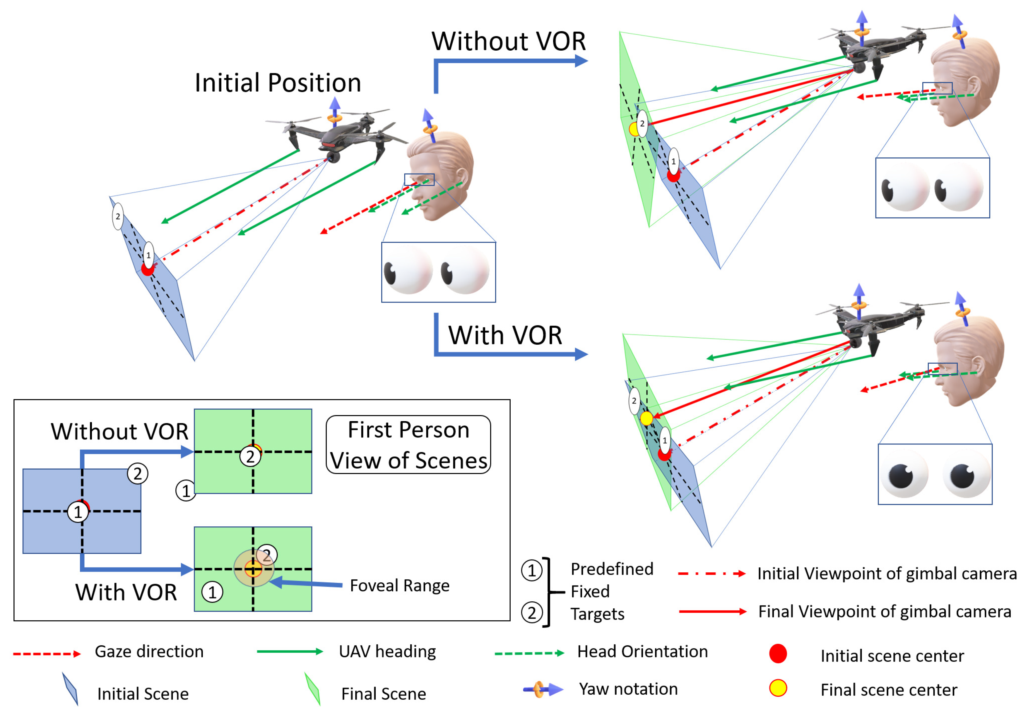
Figure 1 shows the proposed system, where the UAV and on-board gimbal camera behave similar to the human head and eyeball, respectively. Initially, the UAV heading (solid green) and gimbal camera viewpoint (red dot-dash) are parallel, as noted by the arrows. Changes in the viewpoint have a 1:1 correlation with changes in the scene as viewpoint always intersects with the center of the scene. Implementing VOR, the gimbal camera rotates such that there is minimal viewpoint change while pursuing Targets 1–2. This results in Target 2 falling within the foveal range (see Section 2.4). Hence, the viewpoint and UAV heading are no longer parallel, whereas, without implementing VOR, viewpoint change is relatively larger and continue to be parallel with the UAV heading. The first person view represents corresponding scene changes.
Insights from a previously reported experiments [9] were adopted to control the gimbal camera mounted on the DJI Matrice-100 UAV and in simulation. Two target point patterns were set on real-world objects with similar target point positions considered for simulation. The proposed VOR based movement tested on the gimbal camera reduced viewpoint changes up to 7–8%, and simulation results showed 3–4% average reduction in viewpoint changes.
2. Related Work
This section discusses various studies regarding effects of changing viewpoint in virtual environments, rendering methods on HMDs, and gimbal camera trajectory planning.
2.1. Effect of Viewpoint Changes in Virtual Environments
Viewpoint changes in VR systems are crucial. Virtual reality has been defined as where the system immerses the user in a responsive virtual world, which implies dynamic user viewpoint control [10]. Head movement is the most demanding movement, with angular velocity up to 50°/s. Virtual reality systems will seriously damage the illusion of presence when viewpoints change within 150–500 ms.
Eye movement studies have shown that users find it difficult to track objects within changing viewpoints [11]. Object tracking accuracy is 97% with zero viewpoint changes, but reduces to 78% as speed and viewpoint changes varied by 6°/s and 20°/s, respectively. Centered gaze is more stable during abrupt viewpoint changes, and object speed increases. Stability of gaze centered in the scene enhances tracking objects at high speed. Hence, reducing viewpoint changes enables better object tracking.
A similar study considering multiple object tracking under abrupt viewpoint changes shows that 10° change has a comparable accuracy for continuous control conditions [12], whereas 20–30° viewpoint changes impair performance significantly. The results suggest an interesting phenomenon regarding gaze mechanism for object tracking: tracking depends on the human visual system’s ability to compensate for retinocentric coordinates. Hence, object tracking in smaller viewpoint changes is more effective than tracking in larger viewpoint changes.
Various scene navigation techniques have been proposed [13,14]. Navigating in virtual environments can cause various problems for the user. Disorientation increases significantly when the viewpoint os changed abruptly by teleporting the user to new locations in virtual environments [15]. Gaze directed pointing techniques are advantageous, and a viewpoint snapping technique has been proposed [16] to eliminate intermediate frames, making the rotation discrete and more realistic. The snapping technique eliminates viewpoint changes up to 22.5°, making it more comfortable for users.
In our opinion, studies to reduce image rendering and viewpoint changes are essential for VR development, increasing user comfort.
2.2. Rendering on HMD
Various techniques have been proposed to adapt scene rendering to user movement. Most approaches consider head movement, leveraging image RGB data to compute head movement [17]. The study uses a prediction approach to predict the next head movement and hence minimize rendering latency. Feature based head pose estimation has been widely adopted for many HMD systems [18]. The study detects eye and nose tip with an image classifier, and forwards the classified data to a neural network to determine head orientation. Patney et al. [19] proposed foveated rendering to produce images with wider FOV, based on eye fixation regions at faster speed. They tested foveated rendering for gaze tracked HMDs and high resolution desktops.
Koh et al. [20] proposed an adaptive gain adjustment scheme for fine scale image stabilization, using a stabilization device that mimicked human eye and VOR principles. Experimental results suggest that the system can successfully reject up to 10 Hz vibration. This is the first attempt to provide a hardware solution for stabilizing video inspired by the human eye.
2.3. Gimbal Camera Control
Interaction techniques adapt markers and tagging techniques to control camera orientation and angle [21]. However, this approach requires closer range, proper lighting, and efficient object detection algorithms to pass correct control signals to the camera. Camera alignment and angles have also been determined by understanding the geometry of the object the camera is focused on [22].
William et al. [23] proposed UCAM, a real-time camera planner, to control camera angles without human intervention. The proposed system employs cinematographic user models to render customized visualizations of dynamic 3D environments. Most camera control and autonomous planning studies have adapted cinematography techniques [24]. To the best of our knowledge, no software implementation has been previously proposed to autonomously reduce viewpoint changes.
2.4. Foveal Range, Head and Eyeball Movement
Gaze is directly related with the viewpoint. Viewpoint changes are dependent on head roll, pitch, and yaw [25], but changes due to head movement are not generally considered for gaze estimation. This section discusses the effect of head movement (changing viewpoint) on gaze.
Four targets are presented to study VOR function to coordinate head and eye movement and hence acquire visual targets [26], and a significantly linear relationship is evident between gaze and head movement velocities. Gaze and head movement show negligible displacement differences after the target presentation.
Gaze and head movements can be independently controlled [27], indicating that overall gaze and head displacements are linearly related in sinusoidal and intermittent target presentation. However, moment to moment trajectories can be very different and head movements are significantly more variable than gaze movements. Similar build-up of anticipatory head and gaze velocity are observed in opposing directions. For the current study, we considered a linear relationship between head and gaze with respect to its velocities in opposing directions.
We discussed the relationship between FOV and foveal range in our previous work [9]. Gaze usually remains within a specific range within a scene, called the foveal range. We employed the PupilLabs [28] eye tracker to study gaze movement for fixed and moving head cases, with three target point pattern scenarios. For fixed head, foveal range average shifts away from its initial position by 0.22 mm in the normalized coordinate system, whereas the moving head case exhibits 0.03 mm (3%) average shift. Scenarios in [9] provide an important observation that the human eye can converge at the target by compensating eye movement relative to head movement within a small degree of freedom (0.33 mm in the normalized coordinate system). Therefore, we propose an optimal combination of eye and head movement, such that gaze converges at the target point with minimal head movements.
3. Eye Simulation
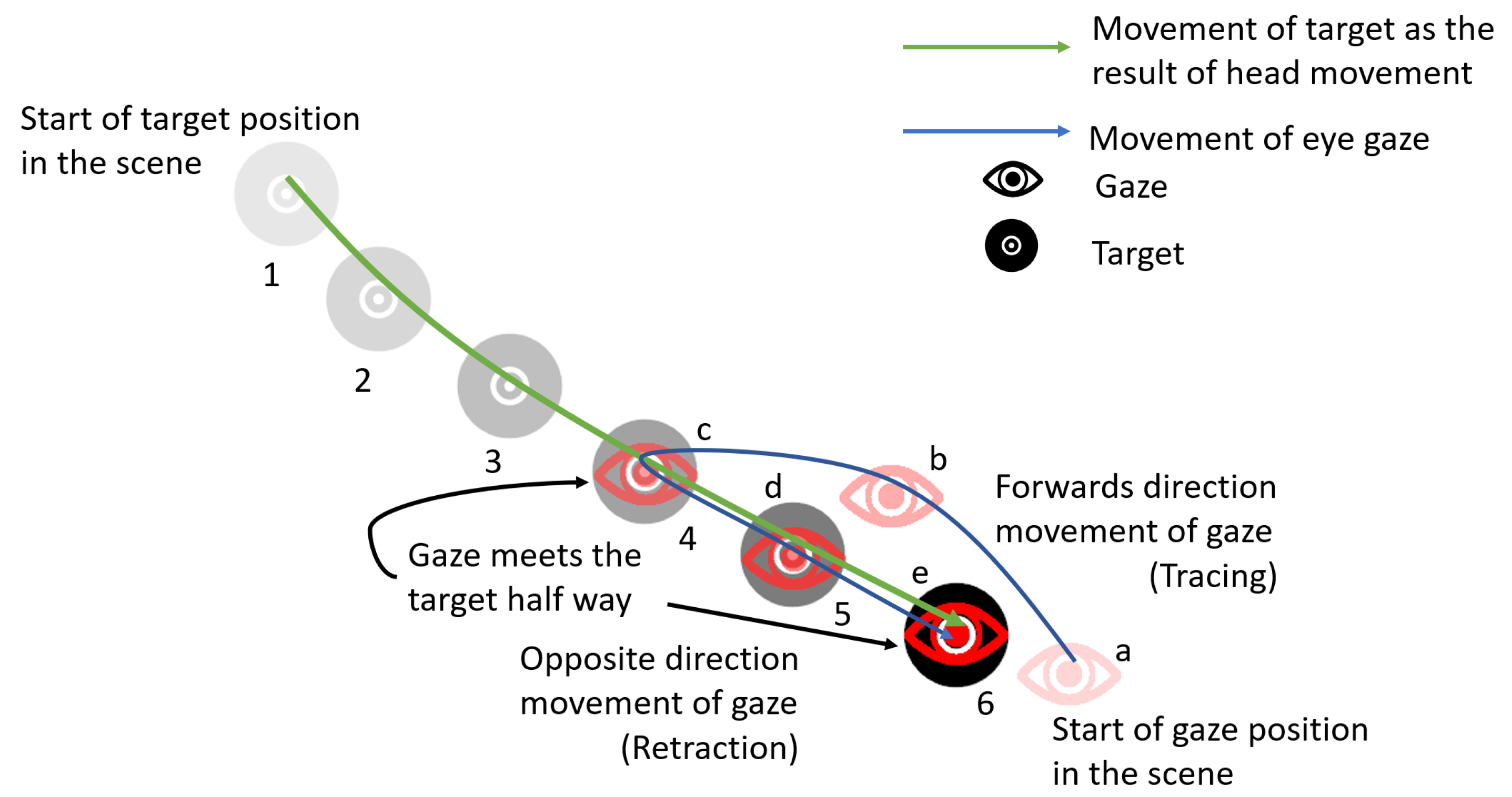
Considering the changes in the head movement, viewpoint changes were simulated using the OpenGL graphics library in C++ on windows platform. This section describes the proposed algorithm. VOR principle is described in Figure 2.
- The eyeball moves up to twice as fast towards the target as the head, which follows behind.
- The head follows the target until the target reaches a comfortable position (within foveal range) within the scene.
- During Step 2, the eyeball remains fixed on the target, moving in the opposite direction from the head to compensate for head movement.
Figure 2 shows that the target is affected by head movement and is in the opposite direction of the head. As indicated, the gaze meets the target halfway, at position “c”, and continues until it comes to a standstill at “e”. The movement from “c” to “e” is retraction and from “a” to “c” is tracing. This approach was adopted for all practical purposes in VOR based implementation.
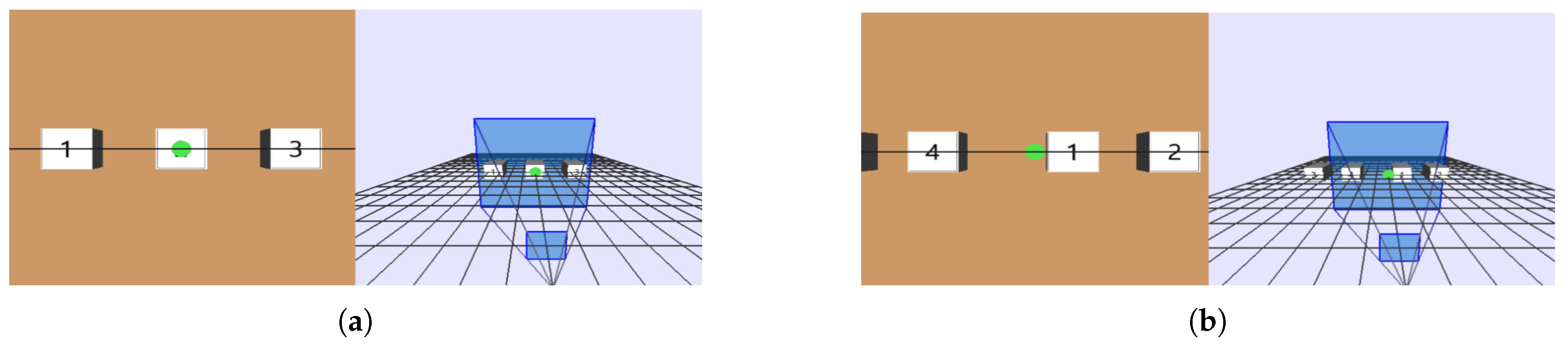
Figure 3a,b shows the two scenarios considered for simulation. Scenario 1 consists of three target points sequentially aligned, whereas Scenario 2 consists of four target points placed in a to and fro pattern, such that head and gaze change direction to and fro while pursuing the targets. The VOR-based gimbal camera implementation is detailed in Section 4. In brief, the UAV hovered at a fixed altitude to pursue target points using only yaw angles. Therefore, although pitch angle movement (Y direction) was possible, we placed the simulation target points on a horizontal plane to maintain consistency with the practical scenarios.
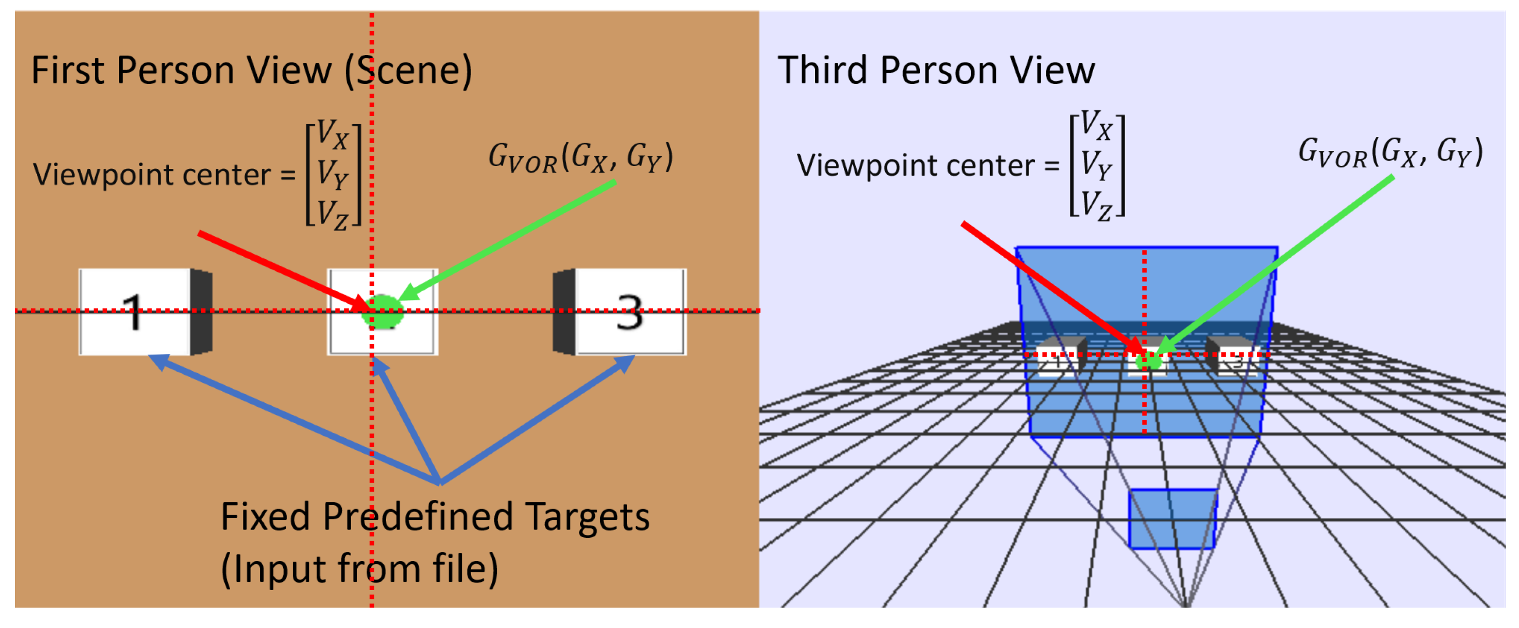
Figure 4 visualizes the simulation variables. The visualization window was divided into first-person (left) and third-person (right) views. The first-person view is the scene whose center intersects with the viewpoint , passing through the center of the rectangular window. Viewpoint changes whenever the vector direction changes, and was updated incrementally based on predefined target point positions, using basic 3D rotation, as shown in Equations (1) and (2). The green dot represents the gaze , which was updated using Equation (3).
Algorithm 1 describes the VOR implementation in simulation. Scenarios were loaded from pre-defined scenario files (.txt), as (X,Y) target point positions in the scene. The scene was divided in to a 40 × 40 grid (20 × 20 in each coordinate of the Cartesian coordinate system). Gaze position, represented as a green dot, was translated within the 1600 cells of the scene.
| Algorithm 1 Vestibular-ocular reflex (VOR) visualization in OpenGL software implementation |
|
Changes in viewpoint and gaze position were made over simulation time. For example, 25 iterations were run for simulation time = 25 s. Changes in viewpoint and gaze position were affected by angle (a and b), which was distributed over the 25 iterations. Viewpoint changed as per Equations (1) and (2) in X and Y directions. Gaze had the same velocity as the head movement, with reversed direction. Hence, gaze reacheed the target approximately twice as fast as the viewpoint (head) (see Equation (3)). However, gaze without VOR followed viewpoint (head) movement and remained at the scene center.
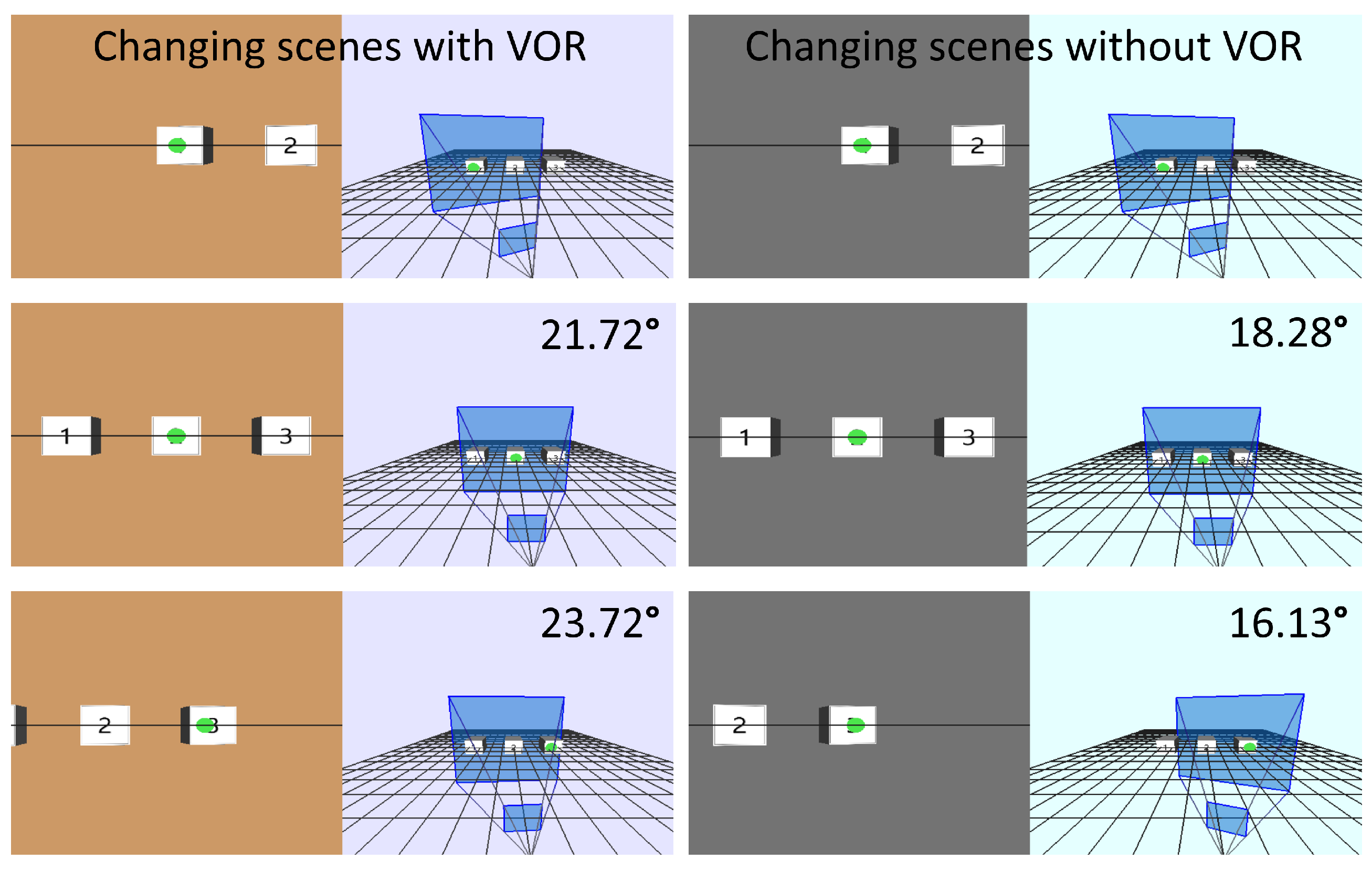
Figure 5 shows third-person simulated views for various gaze and head movements for Scenario 1. Since Target 2 was visible in the viewing window for all three Scenario 1 moves in both cases, Target 2 provided the baseline to calculate target displacement in the scene. Overall viewpoint change, i.e., viewing angle, was approximately 45.53° and 34.41° for head movement without and with VOR, respectively. Target to target changes are shown in Figure 5.
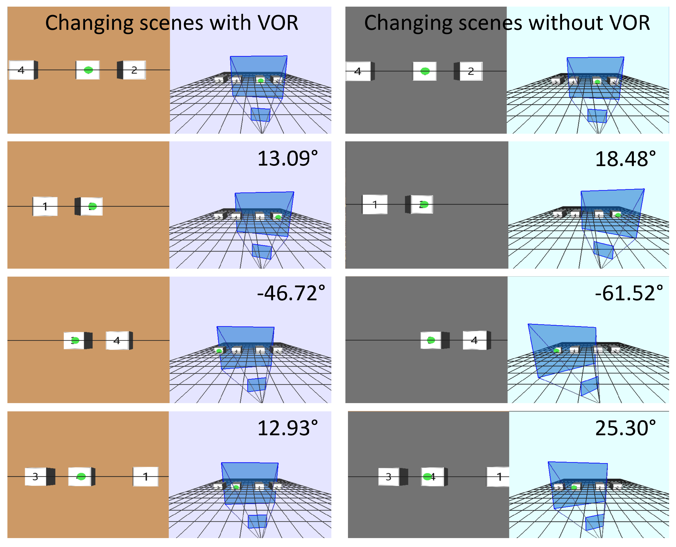
Figure 6 shows third-person simulated views for various gaze and head movements for Scenario 2. Targets 1 and 4 provide baselines to calculate the target displacements in the scene. Similar to the sequential pursuit case, overall viewpoint changes for to and fro target pursuit were minimized by the proposed VOR implementation. Overall viewpoint changes for Targets 1–4 were ° and ° without and with VOR, respectively. Target to target viewpoint changes were minimized by VOR implementation for every step.
4. Gaze-Based Gimbal Camera Movement.
The experiment for gimbal camera VOR based movement was conducted while the Matrice-100 DJI UAV hovered at 1.2–1.5 m. Table 1 and Table 2 show the employed equipment specifications.
4.1. Experimental Setup
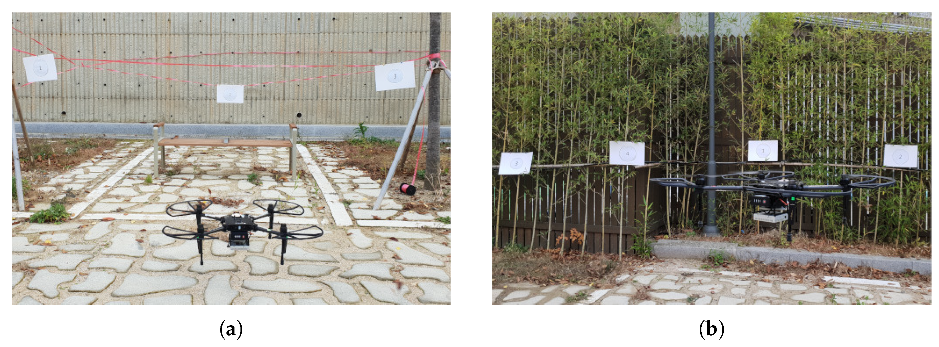
The experiment incorporated two scenarios. Since it was not possible to control the UAV pitch without risking abrupt movements, the following strategy was adopted. Scenario target points were set at 1.2–1.5 m above ground level on a horizontal plane to restrict UAV and gimbal camera movement to yaw angles. Scenario 1 consisted of three target points arranged such that the UAV and gimbal camera moved progressively in a single yaw direction to converge with the target points, as shown in Figure 7a. Scenario 2 consisted of four target points placed in a zigzag pattern, requiring to and fro VOR-based movement in yaw directions, as shown in Figure 7b.
The UAV Yaw movement in the experimental VOR implementation was analogous to head movement, whereas gimbal camera movement was analogous to eyeball movement. The gimbal camera was programmed to change angles based on the VOR principle, considering UAV yaw changes. Target points were markers placed on real-world objects, in the same patterns considered for the simulation scenarios to allow direct comparison between simulation and practical VOR implementation.
4.2. Results
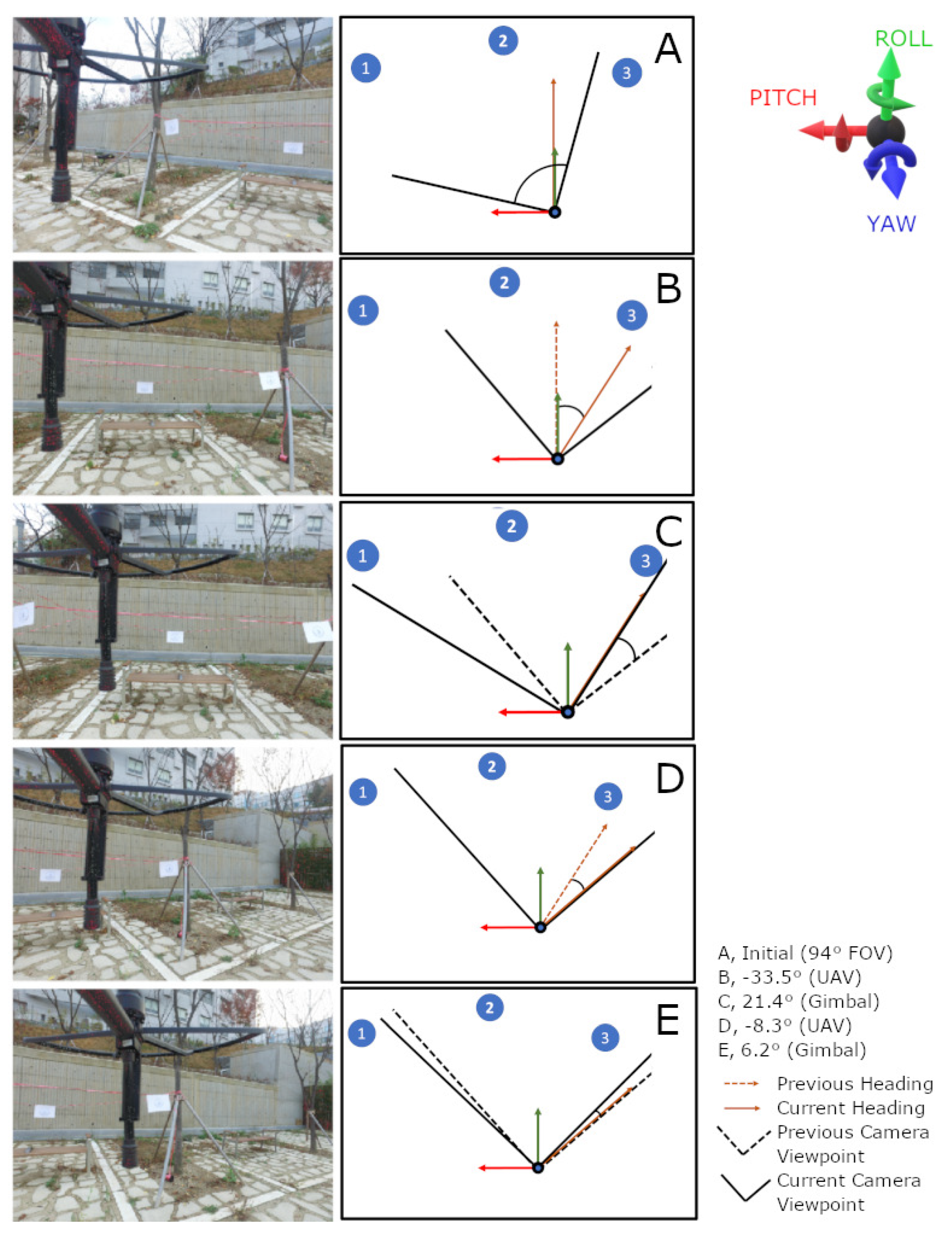
Figure 8 shows the results for Scenario 1. Yaw angles to be pursued by the UAV to converge with the three target points were input from scenario files. The UAV followed the yaw angles, whereas the gimbal camera followed the VOR principle to reduce viewpoint changes. Frame A shows UAV and gimbal camera initial positions. The leading orange line in Figure 8 is the UAV heading (yaw) and the black lines are separated by 94°, i.e., the camera FOV (see Table 1). The UAV and gimbal camera changed their respective angles simultaneously, but are represented alternatively in Frames A–E for clarity. Positive and negative angles represent clockwise and anticlockwise changes, respectively. The current viewing window always remained between the two black lines (camera view), and the UAV heading changed in A–B = °, which was compensated by 21.4° gimbal movement in the opposite direction following the VOR principle. Similarly, the ° UAV heading change was compensated by 6.2° gimbal camera movement to reduce viewpoint change.
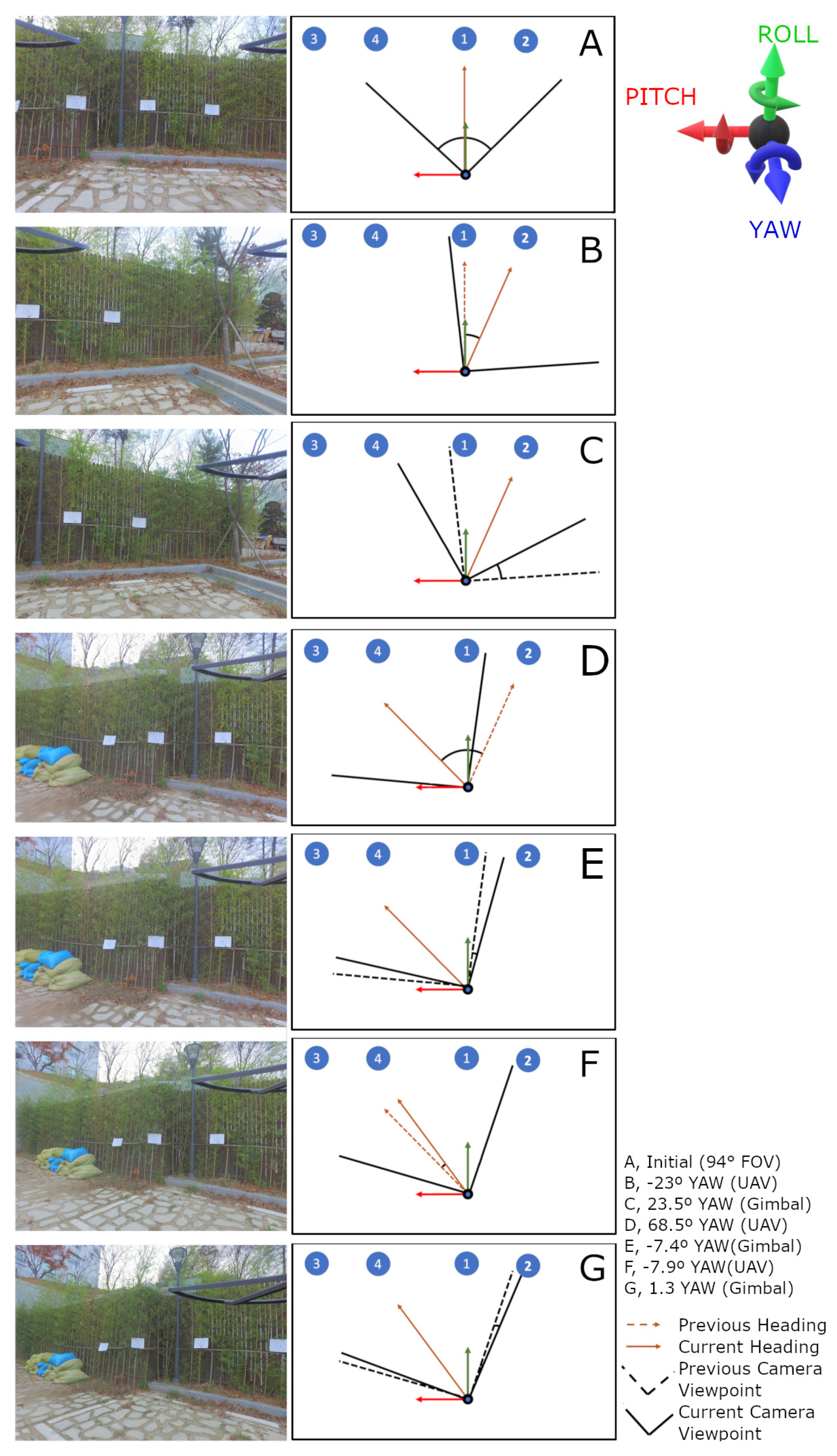
Figure 9 shows the results for Scenario 2, incorporating zigzag target layout. Yaw angles to be pursued by the UAV were predefined and input to the UAV controller through the scenario files. Frames A–G confirm that viewpoint changes were significantly reduced when the gimbal camera implemented VOR.
4.3. Comparison with Simulation
The gimbal mount has a built-in mechanism to compensate for UAV pitch, roll, and yaw movements. For example, when the drone makes a yaw rotation, the gimbal mount compensates the jerky UAV movement, ensuring smooth camera movement in the yaw direction. This enables the camera to have constant viewpoint for small yaw changes. Our experiments did not consider this mechanism and comparison reflects the effect of this phenomenon. Simulated viewpoint changes from target to target were almost linear where the effects of gimbal compensation were null, whereas the experimental VOR gimbal camera implementation exhibited non-significant differences when the targets were close to each other, and, although significantly higher for larger separation, still better than without VOR.
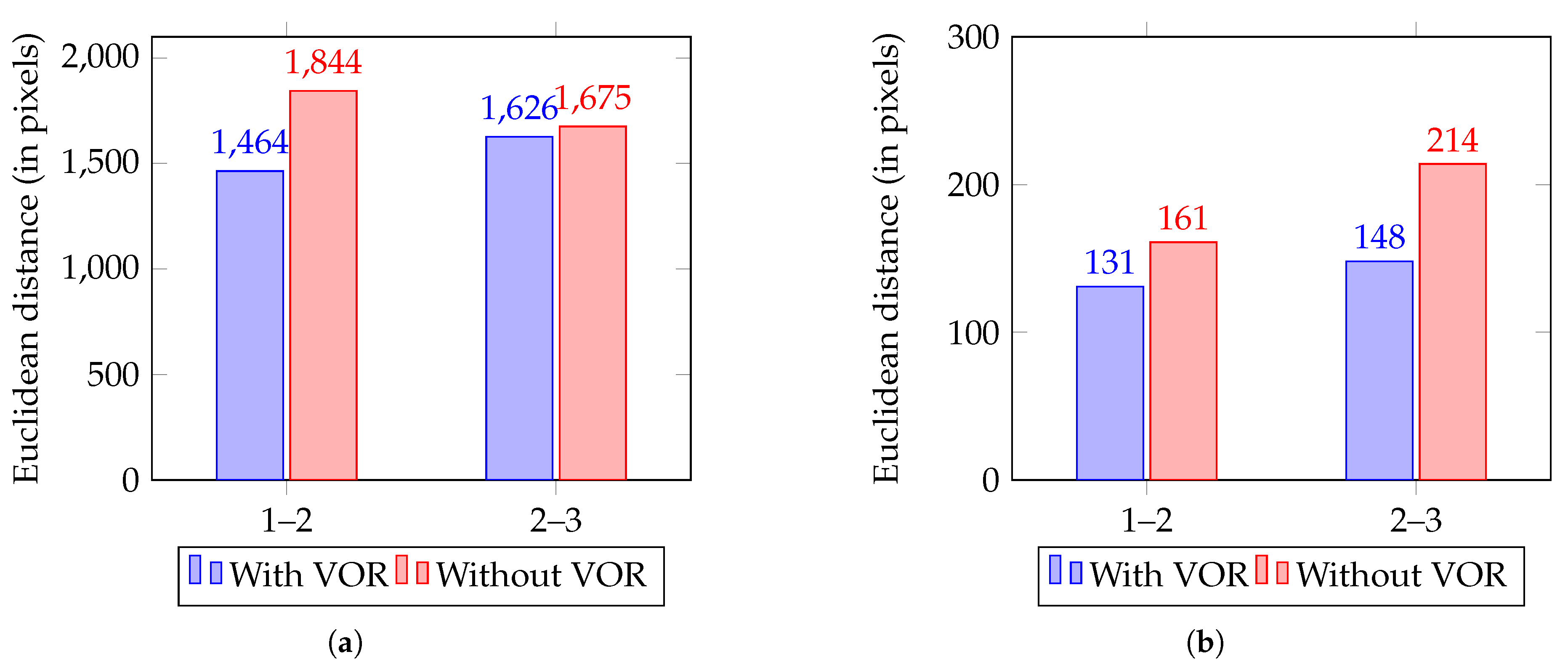
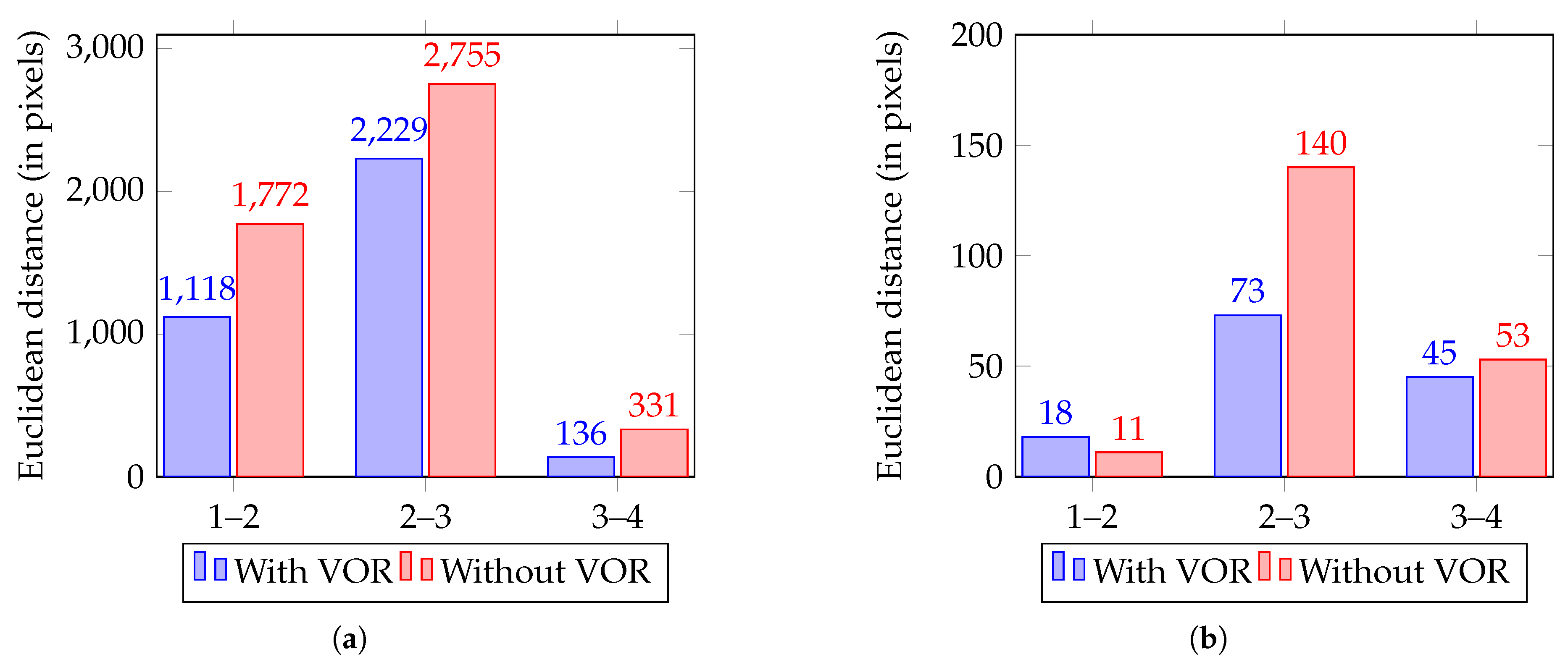
The scenes were recorded as images and changed within 2000 pixels in the gimbal camera implementation and 1000 pixels in the simulation. Figure 10 and Figure 11 show scene changes with and without VOR as Euclidean distance for Scenarios 1 and 2, respectively. Approximately 7–8% improvement was achieved in the gimbal camera implementation since the gimbal’s stabilization mechanism complimented VOR, whereas 3–4% improvement was exhibited in simulation.
5. Conclusions
Although the gimbal intrinsic ability to stabilize jerky UAV movements is necessary at minute scale, controlling gimbal camera movements using VOR provides more realistic and stable images (scenes) on flat monitors. Omnidirectional cameras are very useful to create real-time scenes in virtual environments, with virtual reality systems rendering 360° feed part by part to the HMD based on user head movements. The proposed system can also provide more realistic scene rendering in virtual environments since it considers human gaze as well as head movement.
The PupilLabs eye tracker was essential to investigate the proposed VOR implementation. Although this tracker has some limitations with regard to accuracy, heating, and calibration complexity, it offers better data regarding gaze direction. Since the tracker offered most accurate results immediately after calibration, we re-calibrated every time it was used.
We implemented VOR based gimbal camera movement on the DJI Matrice-100 onboard controller. DJI provided a well-documented software development kit and APIs to control the onboard gimbal camera and UAV yaw. The Matrice-100 provided 1000 g payload and stable flight with 13 min hover time. We employed dual batteries to extend hover time to 40 min during the experiments. Although the Zenmuse X3 gimbal camera had fixed 94° FOV, somewhat less than the human eye FOV (114°), it was sufficient to test the VOR concept at optimal cost.
We considered the previously established effect that viewpoint changes affect foveal range position within the scene by a factor of 0.03 mm (within 3% of the gaze) in normalized coordinates when designing the proposed system. The proposed system achieved 7–8% viewpoint change reduction by implementing VOR, a human eye feature. Hence, the proposed system offers opportunities for VR applications, including games, entertainment, psychology, health care, education, art, marketing, etc.
Future work will explore more avenues to improve the visual system’s apparent realism, and we intend to extend this work to include viewpoint changes while rendering real-time feed from omnidirectional camera to an HMD.
Author Contributions
Conceptualization, A.B., Y.H.C.; methodology, software, A.B.; validation, A.B., P.K.B.N., A.K.P., and Y.H.C.; formal analysis, investigation, resources A.B.; data curation, A.B., P.K.B.N., and A.K.P.; writing—original draft preparation, A.B.; writing—review and editing, A.B., P.K.B.N., A.K.P., and Y.H.C.; visualization, A.B.; supervision, A.K.P. and Y.H.C.; project administration, Y.H.C.; and funding acquisition, Y.H.C.
Funding
This work was supported by the National Research Foundation (NRF) grant (2016R1D1A1B03930795) funded by the Korea government (MEST) and a grant (18CTAPC132982-02) from the Technology Advancement Research Program funded by the Ministry of Land, Infrastructure, and Transport of the Korean Government.
Conflicts of Interest
The authors declare that they have no conflict of interest.
Abbreviations
The following abbreviations are used in this manuscript:
| UAV | Unmanned Aerial Vehicle |
| FOV | Field Of View |
| HMD | Head-Mounted Display |
| VOR | Vestibular Ocular Reflex |
| UCAM | User-Customized Automated Montage |
References
- Wilson, J.R. Virtual environments applications and applied ergonomics. Appl. Ergon. 1999, 30, 3–9. [Google Scholar] [CrossRef]
- Banerjee, P.P.; Luciano, C.J.; Lemole, G.M., Jr.; Charbel, F.T.; Oh, M.Y. Accuracy of ventriculostomy catheter placement using a head-and hand-tracked high-resolution virtual reality simulator with haptic feedback. J. Neurosurg. 2007, 107, 515–521. [Google Scholar] [CrossRef] [PubMed]
- Cruz-Neira, C.; Leigh, J.; Papka, M.; Barnes, C.; Cohen, S.M.; Das, S.; Engelmann, R.; Hudson, R.; Roy, T.; Siegel, L.; et al. Scientists in wonderland: A report on visualization applications in the CAVE virtual reality environment. In Proceedings of the 1993 IEEE Research Properties in Virtual Reality Symposium, San Jose, CA, USA, 25–26 October 1993; pp. 59–66. [Google Scholar]
- Bowman, D.A.; McMahan, R.P. Virtual reality: How much immersion is enough? Computer 2007, 40, 36–43. [Google Scholar] [CrossRef]
- Zhang, X.; Ye, Z.; Zhu, J.-H.; Li, S. Unmanned Aerial Vehicle Flight Simulation and Training System Based on Virtual Reality. Acta Simulata Syst. Sin. 2002, 8, 016. [Google Scholar]
- Ragan, E.D.; Bowman, D.A.; Kopper, R.; Stinson, C.; Scerbo, S.; McMahan, R.P. Effects of field of view and visual complexity on virtual reality training effectiveness for a visual scanning task. IEEE Trans. Vis. Comput. Graph. 2015, 21, 794–807. [Google Scholar] [CrossRef] [PubMed]
- Fetter, M. Vestibulo-ocular reflex. In Neuro-Ophthalmology; Karger Publishers: Basel, Switzerland, 2007; Volume 40, pp. 35–51. [Google Scholar]
- Sko, T.; Gardner, H.J. Head tracking in first-person games: Interaction using a web-camera. In IFIP Conference on Human-Computer Interaction; Springer: Berlin/Heidelberg, Germany, 2009; pp. 342–355. [Google Scholar]
- Adithya, B.; Kumar, B.N.P.; Lee, H.; Kim, J.Y.; Moon, J.C.; Chai, Y.H. An experimental study on relationship between foveal range and FoV of a human eye using eye tracking devices. In Proceedings of the 2018 International Conference on Electronics, Information, and Communication (ICEIC), Honolulu, HI, USA, 24–27 January 2018; pp. 1–5. [Google Scholar]
- Brooks, F.P. What’s real about virtual reality? IEEE Comput. Graph. Appl. 1999, 19, 16–27. [Google Scholar] [CrossRef]
- Huff, M.; Papenmeier, F.; Jahn, G.; Hesse, F.W. Eye movements across viewpoint changes in multiple object tracking. Vis. Cogn. 2010, 18, 1368–1391. [Google Scholar] [CrossRef]
- Huff, M.; Jahn, G.; Schwan, S. Tracking multiple objects across abrupt viewpoint changes. Vis. Cogn. 2009, 17, 297–306. [Google Scholar] [CrossRef]
- Ware, C.; Jessome, D.R. Using the bat: A six-dimensional mouse for object placement. IEEE Comput. Graph. Appl. 1988, 8, 65–70. [Google Scholar] [CrossRef]
- Ware, C.; Osborne, S. Exploration and virtual camera control in virtual three dimensional environments. ACM SIGGRAPH Comput. Graph. 1990, 24, 175–183. [Google Scholar] [CrossRef]
- Bowman, D.A.; Koller, D.; Hodges, L.F. Travel in immersive virtual environments: An evaluation of viewpoint motion control techniques. In Proceedings of the IEEE 1997 Annual International Symposium on Virtual Reality, Albuquerque, NM, USA, 1–5 March 1997; pp. 45–52. [Google Scholar]
- Farmani, Y.Y.; Teather, R.J.R. Viewpoint snapping to reduce cybersickness in virtual reality. In Proceedings of the Graphics Interface 2018, Toronto, ON, Canada, 8–11 May 2018. [Google Scholar]
- Amamra, A. Smooth head tracking for virtual reality applications. Signal Image Video Process. 2017, 11, 479–486. [Google Scholar] [CrossRef]
- Vatahska, T.; Bennewitz, M.; Behnke, S. Feature-based head pose estimation from images. In Proceedings of the 2007 7th IEEE-RAS International Conference on Humanoid Robots, Pittsburgh, PA, USA, 29 November–1 December 2007; pp. 330–335. [Google Scholar]
- Patney, A.; Salvi, M.; Kim, J.; Kaplanyan, A.; Wyman, C.; Benty, N.; Luebke, D.; Lefohn, A. Towards foveated rendering for gaze-tracked virtual reality. ACM Trans. Graph. (TOG) 2016, 35, 179. [Google Scholar] [CrossRef]
- Koh, D.-Y.; Kim, Y.K.; Kim, K.; Kim, S. Bioinspired image stabilization control using the adaptive gain adjustment scheme of vestibulo-ocular reflex. IEEE/ASME Trans. Mechatron. 2016, 21, 922–930. [Google Scholar] [CrossRef]
- Mezouar, Y.; Chaumette, F. Optimal camera trajectory with image-based control. Int. J. Robot. Res. 2003, 22, 781–803. [Google Scholar] [CrossRef]
- Madsen, C.B.; Christensen, H.I. A viewpoint planning strategy for determining true angles on polyhedral objects by camera alignment. IEEE Trans. Pattern Anal. Mach. Intell. 1997, 19, 158–163. [Google Scholar] [CrossRef] [Green Version]
- Bares, W.H.; Lester, J.C. Cinematographic user models for automated realtime camera control in dynamic 3D environments. In User Modeling; Springer: Vienna, Austria, 1997; pp. 215–226. [Google Scholar]
- Christianson, D.B.; Anderson, S.E.; He, L.; Salesin, D.H.; Weld, D.S.; Cohen, M.F. Declarative camera control for automatic cinematography. In Proceedings of the Thirteenth National Conference on Artificial Intelligence, Portland, OR, USA, 4–8 August 1996; Volume 1, pp. 148–155. [Google Scholar]
- Bates, R.; Castellina, E.; Corno, F.; Novák, P.; Štepánková, O. Beyond Communication and Control: Environmental Control and Mobility by Gaze. In Gaze Interaction and Applications of Eye Tracking: Advances in Assistive Technologies; IGI Global: Hershey, PA, USA, 2012; pp. 103–127. [Google Scholar]
- Barnes, G.R. Vestibulo-ocular function during co-ordinated head and eye movements to acquire visual targets. J. Physiol. 1979, 287, 127–147. [Google Scholar] [CrossRef] [PubMed]
- Collins, C.J.S.; Barnes, G.R. Independent control of head and gaze movements during head-free pursuit in humans. J. Physiol. 1999, 515, 299–314. [Google Scholar] [CrossRef] [PubMed] [Green Version]
- Kassner, M.; Patera, W.; Bulling, A. Pupil: An open source platform for pervasive eye tracking and mobile gaze-based interaction. In Proceedings of the 2014 ACM International Joint Conference on Pervasive and Ubiquitous Computing: Adjunct Publication, Seattle, WA, USA, 13–17 September 2014; ACM: New York, NY, USA, 2014; pp. 1151–1160. [Google Scholar]
Figure 1.
Overview of the proposed vestibular-ocular reflex (VOR) based system.

Figure 2.
Vestibular-ocular reflex (VOR) based target and gaze movement. Red eye symbols (a–e) represent the path traversed by the gaze and black concentric circles (1–6) represent the path traversed by the target within the scene.
Figure 2.
Vestibular-ocular reflex (VOR) based target and gaze movement. Red eye symbols (a–e) represent the path traversed by the gaze and black concentric circles (1–6) represent the path traversed by the target within the scene.

Figure 3.
Simulation scenarios: (a) Scenario 1, sequential pattern; and (b) Scenario 2, to and fro pattern.
Figure 3.
Simulation scenarios: (a) Scenario 1, sequential pattern; and (b) Scenario 2, to and fro pattern.

Figure 4.
Visualization of simulation variables.

Figure 5.
Gaze and head movement simulation for Scenario 1 (left) with and (right) without vestibular-ocular reflex (VOR). Gaze point is represented as the green dot.
Figure 5.
Gaze and head movement simulation for Scenario 1 (left) with and (right) without vestibular-ocular reflex (VOR). Gaze point is represented as the green dot.

Figure 6.
Gaze and head movement simulation for Scenario 2 (left) with and (right) without vestibular-ocular reflex (VOR). Gaze point is represented as the green dot.
Figure 6.
Gaze and head movement simulation for Scenario 2 (left) with and (right) without vestibular-ocular reflex (VOR). Gaze point is represented as the green dot.

Figure 7.
Scenario for vestibular-ocular reflex (VOR) based gimbal camera movement to achieve pre-defined targets: (a) Scenario 1; and (b) Scenario 2.
Figure 7.
Scenario for vestibular-ocular reflex (VOR) based gimbal camera movement to achieve pre-defined targets: (a) Scenario 1; and (b) Scenario 2.

Figure 8.
Gimbal and UAV yaw angle changes for Scenario 1: (left) photographs from various camera and UAV positions; and (right) third-person view showing the angles.
Figure 8.
Gimbal and UAV yaw angle changes for Scenario 1: (left) photographs from various camera and UAV positions; and (right) third-person view showing the angles.

Figure 9.
Gimbal camera and UAV yaw movements for Scenario 2.

Figure 10.
Scene changes with and without vestibular-ocular reflex (VOR) for Scenario 1: (a) gimbal camera; and (b) simulation.
Figure 10.
Scene changes with and without vestibular-ocular reflex (VOR) for Scenario 1: (a) gimbal camera; and (b) simulation.

Figure 11.
Scene changes with and without vestibular-ocular reflex (VOR) for Scenario 2: (a) gimbal camera; and (b) simulation.
Figure 11.
Scene changes with and without vestibular-ocular reflex (VOR) for Scenario 2: (a) gimbal camera; and (b) simulation.


Table 1.
DJI Matrice-100 UAV specification.
| DJI Matrice 100 | |
|---|---|
| Hover accuracy | Vertical: 0.5 m Horizontal: 2.5 m |
| Maximum angular velocity | Pitch: 300°/s Yaw: 150°/s |
| Maximum speed | 17 m/s (GPS mode, no wind) |
| Hover time | 1140 s |
Table 2.
Zenmuse-X3 gimbal camera specification.
| Zenmuse X3 | |
|---|---|
| Zenmuse X3 with camera weight | 247 g |
| Field of view | 94° |
| Controllable range | Pan: ±320° |
| Maximum controllable speed | Pan: 180°; Tilt: 120° |
© 2019 by the authors. Licensee MDPI, Basel, Switzerland. This article is an open access article distributed under the terms and conditions of the Creative Commons Attribution (CC BY) license (http://creativecommons.org/licenses/by/4.0/).
Share and Cite
MDPI and ACS Style
B., A.; B. N., P.K.; Chai, Y.H.; Patil, A.K. Inspired by Human Eye: Vestibular Ocular Reflex Based Gimbal Camera Movement to Minimize Viewpoint Changes. Symmetry 2019, 11, 101. https://0-doi-org.brum.beds.ac.uk/10.3390/sym11010101
AMA Style
B. A, B. N. PK, Chai YH, Patil AK. Inspired by Human Eye: Vestibular Ocular Reflex Based Gimbal Camera Movement to Minimize Viewpoint Changes. Symmetry. 2019; 11(1):101. https://0-doi-org.brum.beds.ac.uk/10.3390/sym11010101
Chicago/Turabian StyleB., Adithya, Pavan Kumar B. N., Young Ho Chai, and Ashok Kumar Patil. 2019. "Inspired by Human Eye: Vestibular Ocular Reflex Based Gimbal Camera Movement to Minimize Viewpoint Changes" Symmetry 11, no. 1: 101. https://0-doi-org.brum.beds.ac.uk/10.3390/sym11010101
Note that from the first issue of 2016, this journal uses article numbers instead of page numbers. See further details here.