Article

Basket-Handle Arch and Its Optimum Symmetry Generation as a Structural Element and Keeping the Aesthetic Point of View

by
Alfredo Alcayde
1,
Cristina Velilla
2,
Carlos San-Antonio-Gómez
2,
Araceli Peña-Fernández
1,3,
Antonio Pérez-Romero
4 and
Francisco Manzano-Agugliaro
1,3,*
1
Department of Engineering, University of Almeria, ceiA3, 04120 Almeria, Spain
2
Department of Ingenieria Agroforestal, Universidad Politécnica de Madrid, Av. De Puerta de Hierro, 28040 Madrid, Spain
3
Research Centre CIAIMBITAL, University of Almeria, ceiA3, 04120 Almeria, Spain
4
Graphic Engineering Department, University of Sevilla, Utrera Road, km 1, 41013 Sevilla, Spain
*
Author to whom correspondence should be addressed.
Submission received: 8 July 2019 / Revised: 1 September 2019 / Accepted: 19 September 2019 / Published: 4 October 2019
(This article belongs to the Special Issue Symmetry in Engineering Sciences II)

Abstract

:
The arches were a great advance in construction with respect to the rigid Greek linteled architecture. Its development came from the hand of the great Roman constructions, especially with the semicircular arch. In successive historical periods, different types of arches have been emerging, which in addition to their structural function was taking aesthetic characteristics that are used today to define the architectural style. When, in the construction of a bow, the rise is less than half the springing line, the semicircular arch is no longer used and the segmental arch is used, and then on to another more efficient and aesthetic arch, the basket-handle arch. This study examines the classic geometry of the basket-handle arch also called the three-centered arch. A solution is proposed from a constructive and aesthetic point of view, and this is approached both geometrically and analytically, where the relationship between the radius of the central arch and the radius of the lateral arch is minimized. The solution achieved allows the maximum springing line or clear span to be saved with the minimum rise that preserves the aesthetic point of view, since the horizontal thrust of a bow is greater than the relationship between the springing line of the arch and the rise. This solution has been programmed and the resulting software has made it possible to analyse existing arches in historic buildings or constructions to check if their solutions were close or not from both points of view. Thus, it has been possible to verify that in most of the existing arches analyzed, the proposed solution is reached.

Graphical Abstract

1. Introduction

The arch is a constructive and structural element whose origin must be sought in the Chaldean architecture of the third millennium BC [1]. Its fundamental development was in the architecture of the great Roman constructions, which surpassed the rigid Greek lintel architecture and allowed them to build immense structures such as thermal baths, bridges and aqueducts [2]. In Rome, the usual arch was the semicircular one, that is to say the arch formed by a semicircle in which its center is at the height of the imposts, the reason why its rise is equal to the half of its clear span or springing line [3]. The variants of the semicircular arch, also used by the Romans, are the stilted arch, whose rise is greater than the half of the clear span; and the segmental arch, which differs from the semicircular arch in that the centre of the circumference is below the line of imposts, so that the circumference is no longer tangent to the walls or pillars where the arch starts.
The semicircular arch with its respective types, see Figure 1A, such as the stilted arch, Figure 1B, the segmental arch, Figure 1C, or the arch which is attached to the barrel vault of a nave to reinforce it and divides it into sections, were also characteristic of Romanesque architecture [4]. However, it lost importance in the Gothic, which gave way to the three-pointed arch, Figure 1E, with its different variants, as an acute arch, Figure 1G, or the depressed arch, Figure 1H [5].
At the end of the Gothic, a new arch spread with force until well into the Renaissance and even in the Baroque: The basket-handle arch [6], Figure 1D. The basket-handle arch is a symmetrical arch composed of a succession of circumferential arches tangent to each other and with the supports, see Figure 2A.
It is important to emphasize that there are aesthetic conditions that have sometimes made the rules and procedures inspired by nature, e.g., trunks, and branches that simulate arches or vaults [7]. Other examples of arches should be cited, such as the Sicilian-Catalan arch (closely related to the main topic of the research), or the Ottoman arch, Figure 1K, fundamental in the history of such a technical element. Examples of these arches can be found in the literature, especially for bridges, e.g., Malabadi Bridge [8]. It should be noted that the arches have generally been made with stone masonry, but there are examples made of wood, as the decorative elements in churches, especially the Catholic one, e.g., Borgund church (Norway) [9,10].
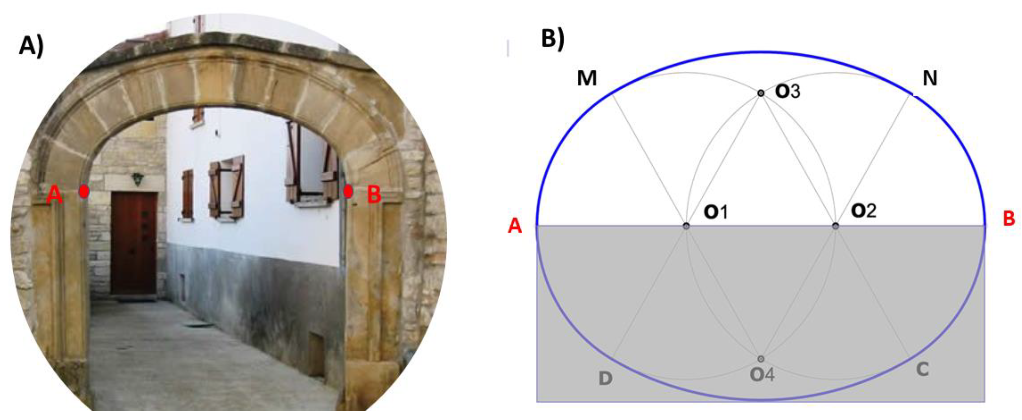
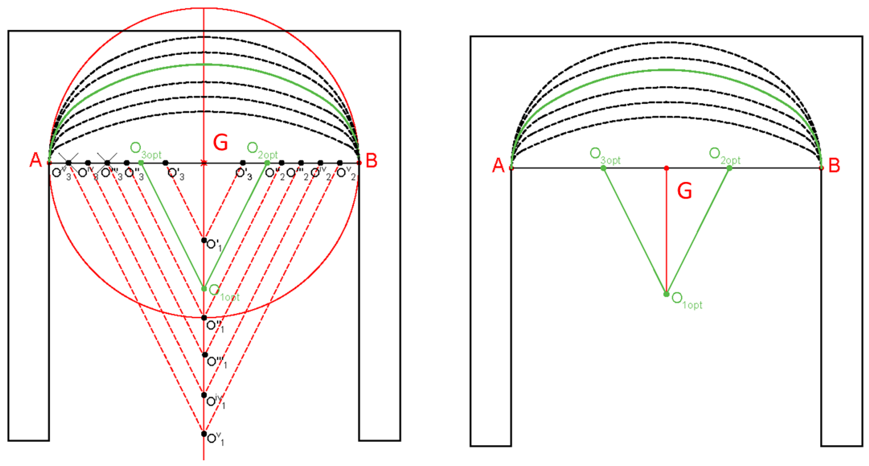
The most standard the basket-handle arch is made up of three circumferential arches, although arches of five, seven and nine centers can also be formed. The number of arches is as many as the smaller the rise in relation to the clear span, in any case, the number of arches of circumference is always odd. The basket-handle arch is precisely the upper half of an oval (Figure 2B).
The basket-handle arch was widely used in Spain at the end of the Gothic style and in the Plateresque style, where there are interesting examples both in gates of emblematic buildings and in the anonymous architecture of towns and villages [11]. In the facades of the great Plateresque buildings, there are important examples such as in the universities of Alcala and Salamanca, see Figure 3. In the American Spanish territories, the Plateresque style spread and therefore, there are examples of this architectural style.
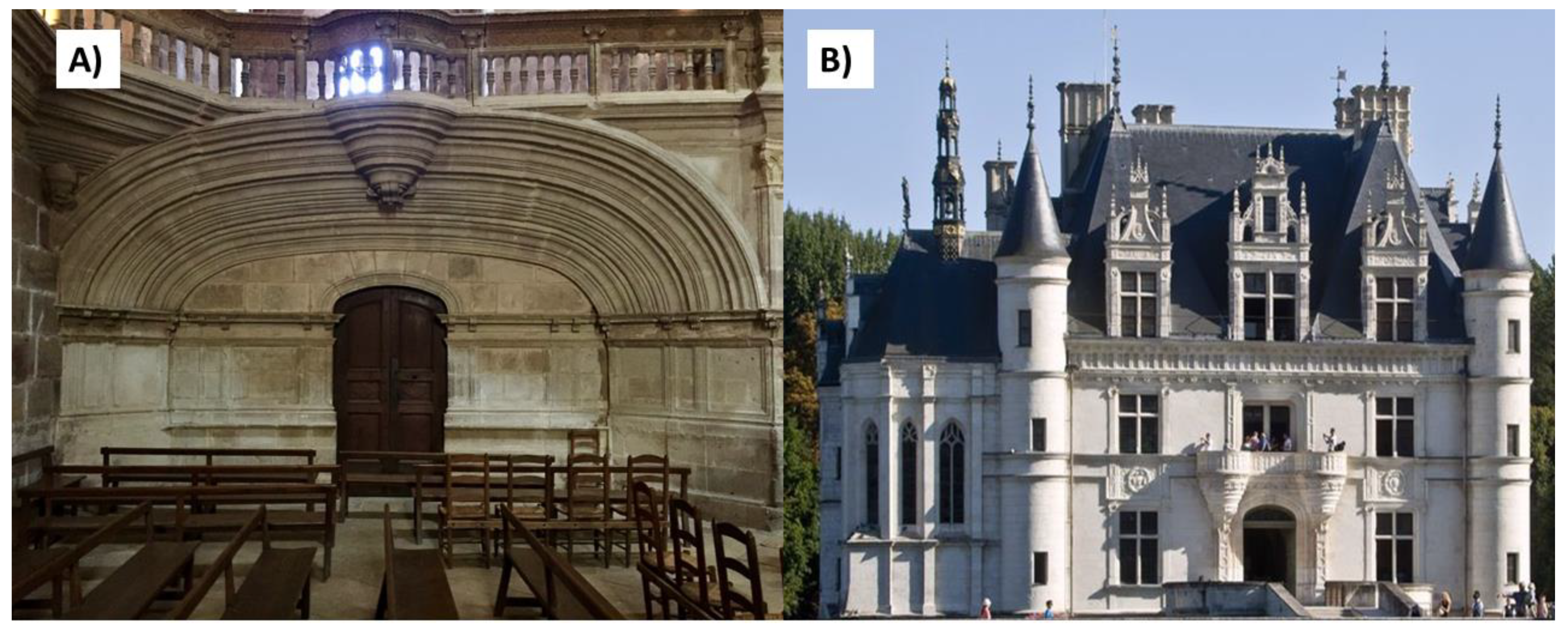
In France, great examples can be found in the four rooms that form a cross on the famous open staircase of the Château de Chambord, the largest of the Loire castles (Figure 3), or inside the cathedral of de Rodez (Figure 4A). Another example is the gateway to Chenonceau (Figure 4B), another of the Loire castles.
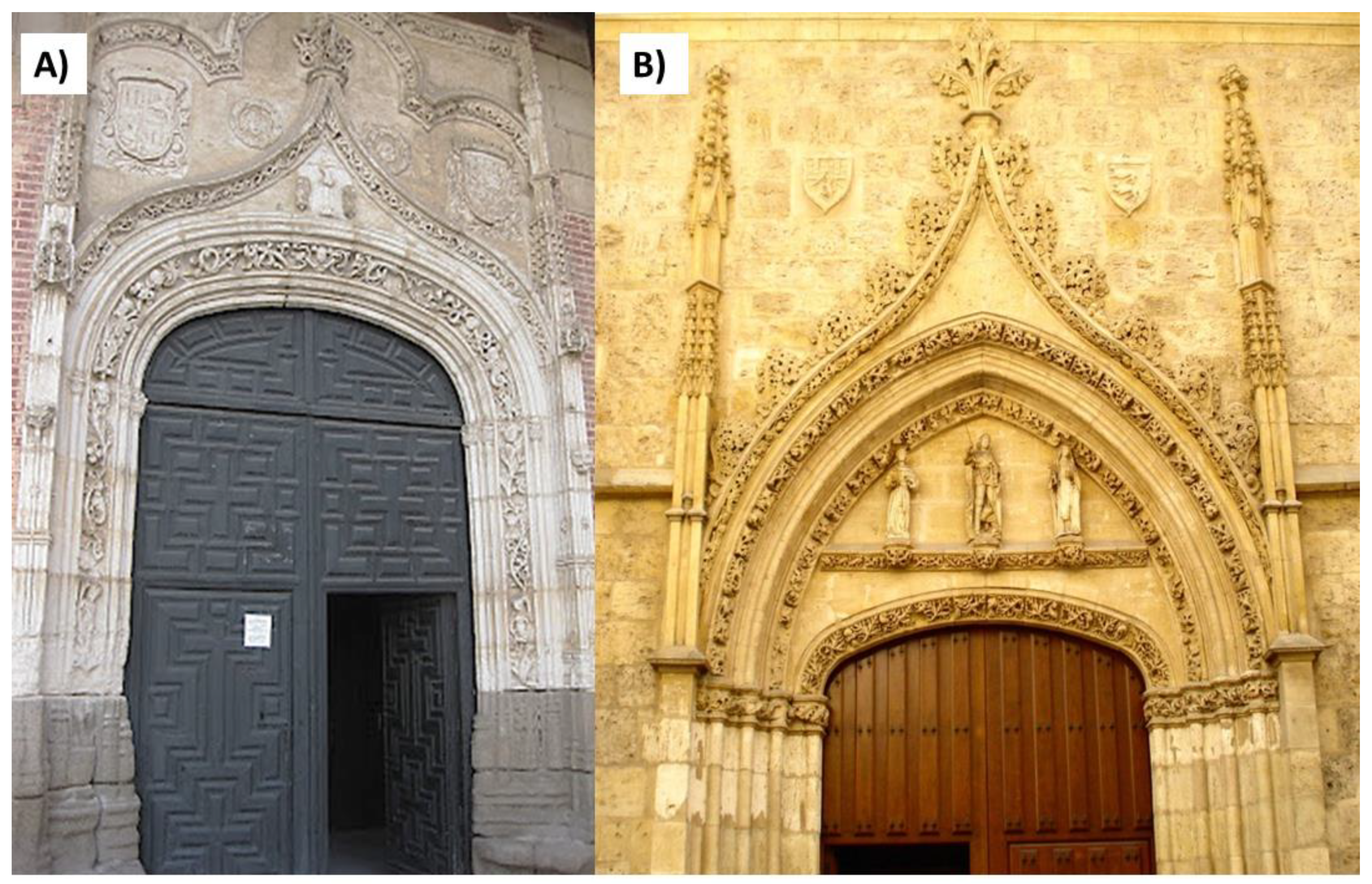
The basket-handle arch is sometimes combined with the ogee or inflected arch, widely used in 14th and 15th century architecture [12], which is a pointed arch made up of four circumferential arches, two interior arches with a concave shape and two upper convex arches. Among the many examples, there is the gate of the Monastery of San Antonio el Real, by the architect Juan Guas, located in Segovia, Figure 5A. It is also the case to integrate in the same façade the basket-handle, the ogee and the gothic arches as, for example, in the Monastery of Santa Clara located in Palencia (Spain), Figure 5B).
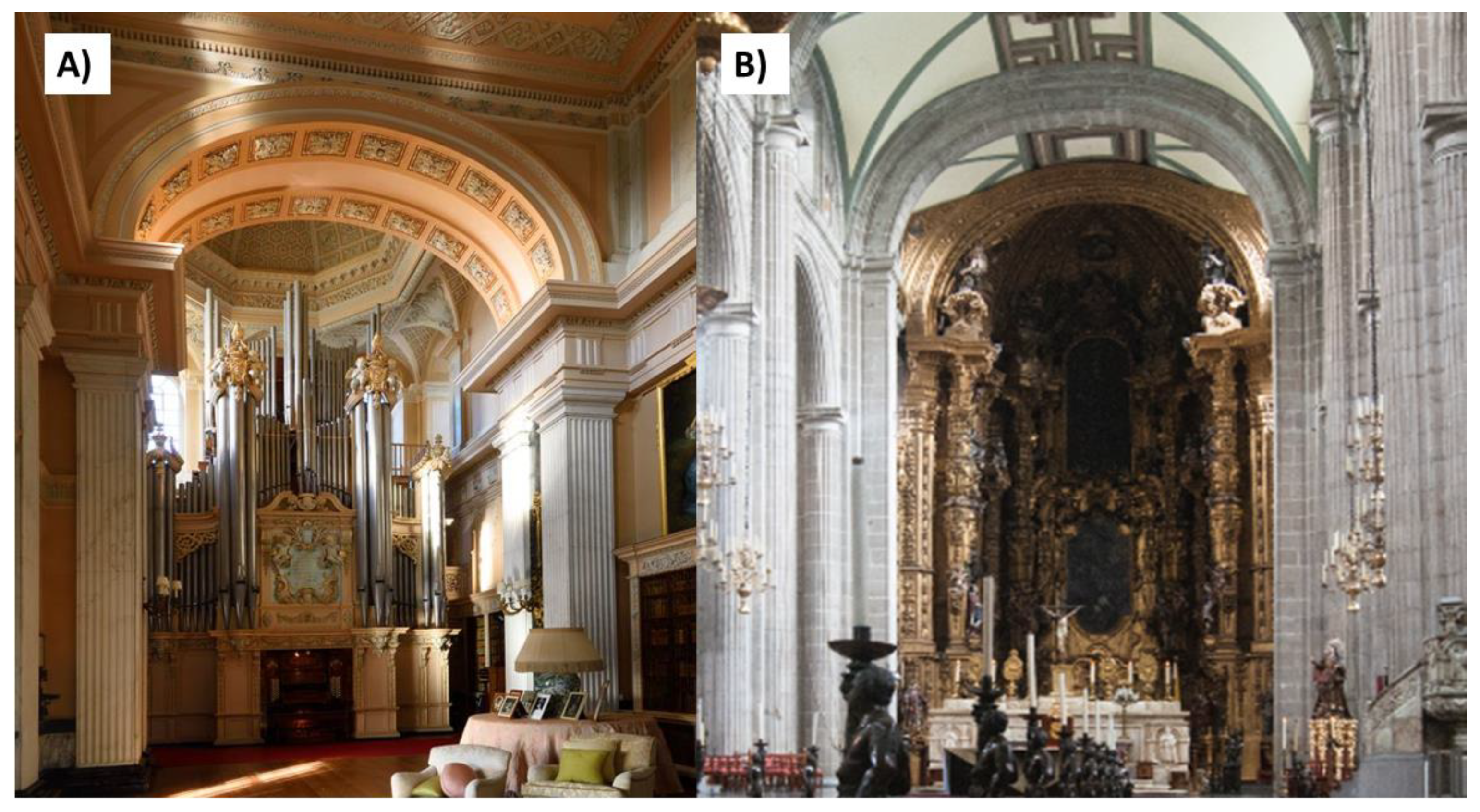
The basket-handle arch was also used in Baroque architecture on both sides of the Atlantic. For example, the sumptuous arches of Blenheim Palace, a monumental country residence located at Woodstock in Oxfordshire County, England, which is the residence of the Dukes of Marlborough, built between 1705 and 1722, see Figure 6A. In Spanish America, there are many examples from both the Plateresque and Baroque periods where the arches of the Primate Cathedral of Mexico City can be cited, see Figure 6B.
With the recovery of the historical styles of the late nineteenth and early twentieth centuries, again the basket-handle arches are found as, in the Plaza de España in Seville (Spain), where they appear on marble columns with Corinthian capitals in the outer archery and on brick cores in the porches of those arches (
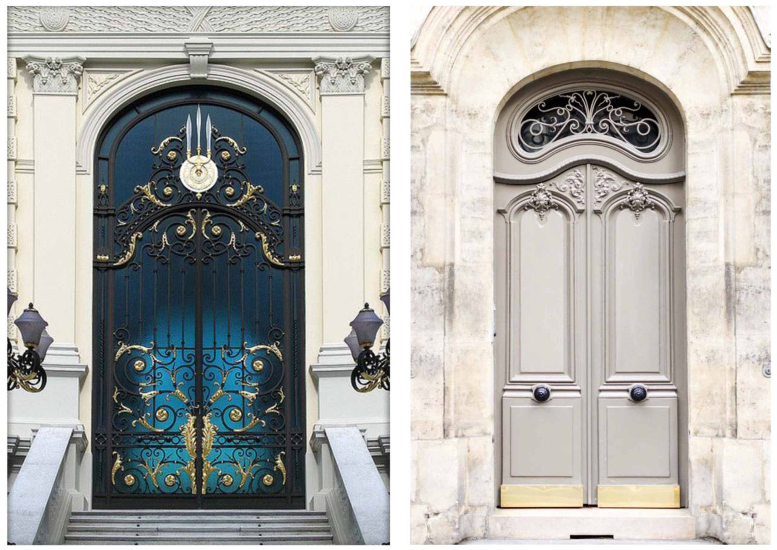
Figure 7). Likewise, in Modernism, in its formal search for a new architecture, it recovers the arc of the basket-handle arch as opposed to the semicircular arch used, almost exclusively, in the neoclassical period that precedes it (Figure 8). Therefore, not only monumental examples are given because, in reality, the element arch is a widely used constructive technology, even in the ordinary architecture.
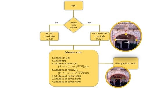
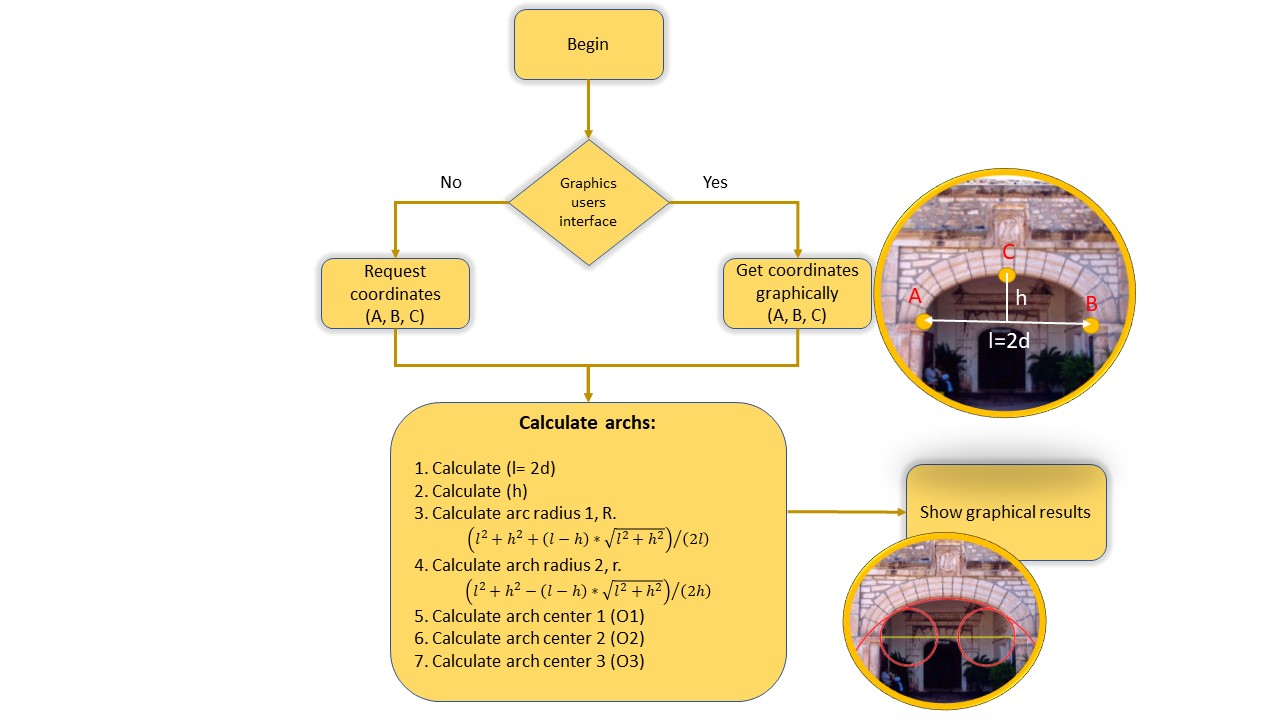
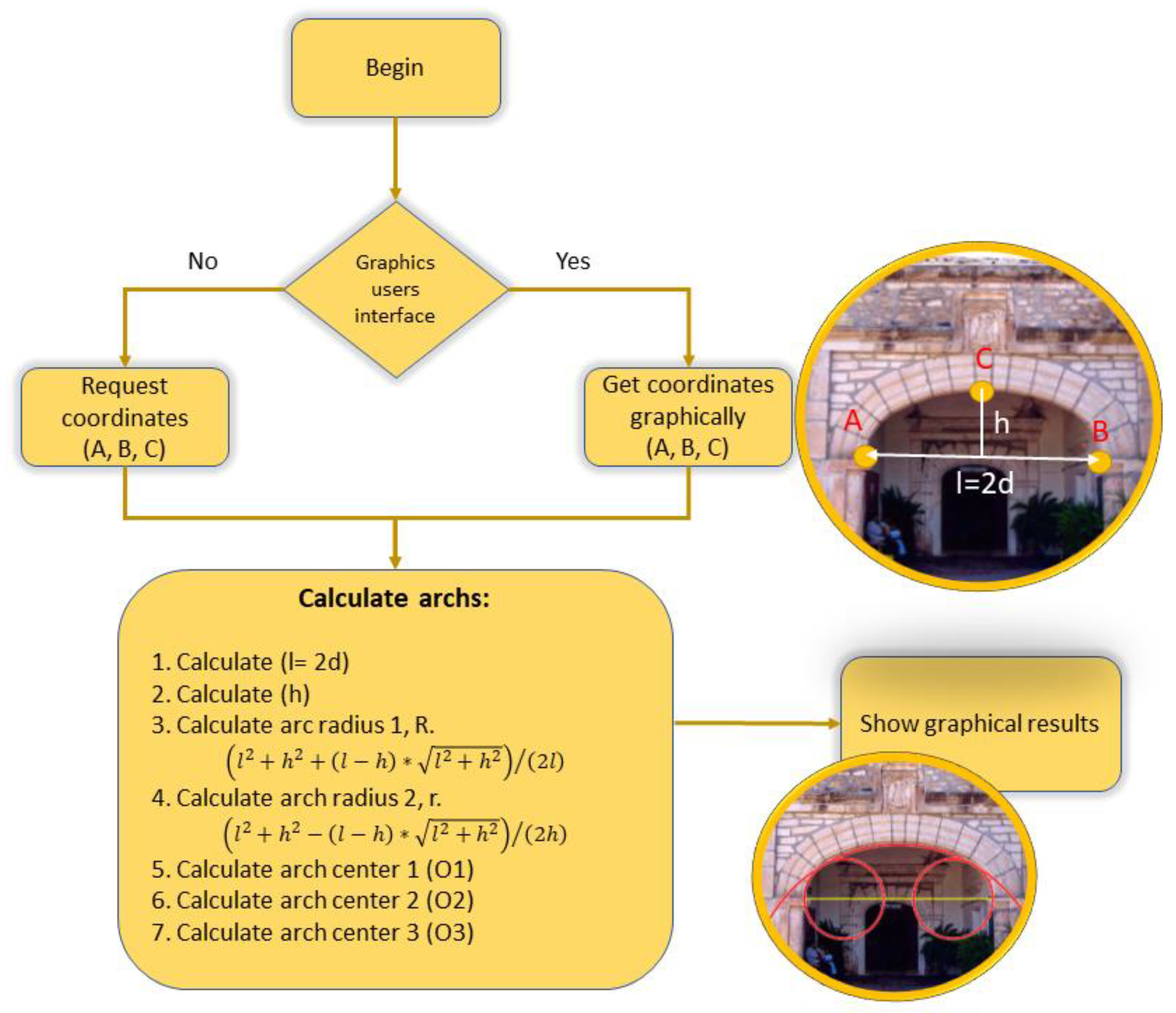
The design of a basket-handle arch does not present any difficulty as is seen below. However, there is no consensus on which is the optimal basket-handle arch. The objective of this work is to review the state of the art in the execution of the basket-handle of three arches, define which is the optimal arch geometry as a structural element in the construction, calculate the numerical solution and program it for its calculation and verification of existing arches.

2. Basket-Handle Arch in Architecture

The geometric approach to the design and construction of safe factory buildings has been used since ancient times by master builders in buildings, such as the Pantheon in Rome or Gothic cathedrals [13,14]. The Theory of Structures aims at the project of safe constructions. Considering only equilibrium solutions that respect the essential characteristic of the material, in that it only resists compressions, it has proven to be the most suitable for the analysis and design of masonry structures [15]. Heyman’s modern theory, based on equilibrium, is the most effective for understanding masonry constructions or structures where equilibrium states depend on geometry [15].
In the case of the analysis of masonry arches, it is necessary to assume three main conditions [14]: Masonry has no tensile strength; it can withstand infinite compression; and there will be no slippage between the pieces that make up the arch, due to the high friction coefficient between the stones. Several studies provide additional background on limit analysis for masonry arches [16].
The basic element of a masonry structure is the arch. Analyzing the equilibrium, a geometric place is found where the centers of thrust form a line, line of thrusts, whose shape depends on the geometry of the arch, the loads and the joints between the pieces. The solution for a stable arch is not unique, since there are infinite lines of thrust that can be contained within all the pieces that make it up. Thus, the equilibrium of the arch can be shown by the line of thrust, which is a theoretical line representing the path of the resulting compressive forces. The concept was first formulated in the 19th century by Moseley in 1833 [13,14,15,16,17] and redefined at the beginning of the 20th century by Milankovich in 1907 [14,15,16,17,18].
The analysis of limit states, using thrust lines, can establish the relative stability of the structures, as well as the possible collapse mechanisms. The development of interactive tools based on the analysis of thrust lines for masonry structures, using graphical computation, allows establishing the relationship between the structural behaviour of an arch and its geometry [18].
The inclined thrust existing in each element of the arch translates into one vertical (due to weight) and one horizontal (thrust of the arch). There is a maximum thrust corresponding to the most stretched line (Figure 9). The thrust is maximum when the line is tangent to the intrados in correspondence with the section of the keystone of the arch, and is inserted into the abutments or imposts [19], see Figure 9 in red. The minimum line of thrust corresponds to the one that is tangent to the back of the arch, see Figure 9 in blue.
In an arch it is considered that there are no moments in the junctions between stones, being supported on each other, nor in the extreme supports. The only force to be of concern is the horizontal thrust of the arch, since the horizontal thrust of a bow is greater, the greater the relationship between the springing line of the arch and the rise. The stilted arches can give horizontal thrusts smaller than segmental arches.
In ancient architecture, the thrust forms a polygon in whose vertices are applied on the weights of each voussoir (see Figure 9, pieces of stone that make up the arch), can be considered as a system of articulated bars. In the case of a symmetrical arch, the horizontal thrust of its centre corresponds to the reaction in the support, being null in the centre when balancing the two halves of the arch (two unstable semi-arches are transformed into a stable arch) [12,13,14,15,16]. The problem is to know the thrust of the arch in position, magnitude and direction, and then verify by static, the stability of the arch springer. In the case of monolithic stone springer, the result of the reaction is the composition between the horizontal thrust and its weight. In order to avoid slipping and to avoid that the resultant one is in the line of the angle, the stones that compose the abutment were inclined to a certain angle in a coincident way with the angle of friction of the material. This solution was used in very stretched arches.
The normal way was to have staggered abutments, or formed by pieces of the increasing section towards the base of the same one, to obtain that the resulting one remained inside when the push was excessive (low arches) or to load the abutments with weights in order to avoid the turn.
When friction is high (µ > 0.7), as is the case with limestone including marble, the stones that make up the arch (voussoir) do not slide between them, and the supports receive high compressive loads that can induce plastic deformations [20]. Basket-handle arches are lowered arches, which would collapse due to the sinking of the keystone (central part of the arch, see Figure 8), and the tilting of the lower sides towards the outside of the arch, a problem that can be solved by filling or solidifying this area. It should be noted that of the infinite possible directions of the arch’s fracture, the vertical is the most crucial as it results in the greatest minimum thickness value of an elliptical arch needed to support its own weight. In addition, in the case of mortars joining the elements that make up the arch perpendicular to the line of intrados, the fracture pattern is the greater value of the minimum thickness allowed [21]. According to this, for a semi arch of clear span or width 2d, height h and thickness t, exposed to its own weight, the minimum thickness obtained to maintain the equilibrium corresponds to the lowest ratio h/2d. That is, the lowered arches, among which is the basket-handle arch, and the greatest thickness would be obtained for the stilted arches. For the arch as a structural element, higher safety factor values are obtained in the lowered arches [22].
From the equilibrium analysis of an arch under external loads, it can be deduced that of the probable thrust lines that satisfy these conditions, the one closest to the geometric axis corresponds to the one that generates the lowest values of the bending moment and shear force in the transversal sections., Thus, it generates a better and uniform distribution of the compressive efforts transmitted through the section itself. It is possible to calculate the safety of the arches, establishing a factor of the degree of safety of the structure, based on the line of thrust contained inside the arch. Heyman suggested reducing the thickness of the arch by changing the extrados and intrados profiles in a homothetic way until they touch the line of thrust. The result is an ideal arch, of reduced thickness, contained within the real arch. The relationship between the thickness of the actual arch and the thickness of the ideal arch that defined it as the safety geometric factor (hreal/hideal) of the structure. This factor gives an idea of the safety of the arches. To calculate the exact value of the geometric safety factor can be arduous, but it is possible to obtain a lower limit easily, for example for a factor of 2, it is expected to be enough to be able to draw a line of thrusts inside the central half of the arch.
The inverse approach to that proposed by Heyman, is based on obtaining the ideal arch in which the line of thrust moves up and down, until it becomes tangent to the curve intrados and extrados of the real arch at least one point, while remaining within its profile [22]. The result is a region that represents the domain of all probable thrust lines, parallel to those provided by the analysis, wholly contained within the thickness of the arch. By doing so, the safety geometric factor, calculated as the ratio between the actual arch thickness and the ideal arch, measured in the vertical direction, can be denoted as the “full safety range factor”. Heyman’s geometrical factor is a number that increases as the thickness of the arch decreases and is between 1 and infinite, this value being the maximum safety value because the line of thrust coincides exactly with the geometrical axis of the arch in this case. While the full range factor ranges from 0 (maximum risk, unstable arch) to 1 (maximum stability arch). This maximum safety condition means that the shape of such an arch (i.e., its geometric axis) matches exactly the load funicular, i.e., the shape of an inverted catenary. The arch safety evaluation methodology, based on a purely geometric formulation, makes it possible to determine that the thrust line of an arch of constant thickness, subject to its own weight, coincides with its geometric axis, only if the shape of the axis corresponds exactly to an inverted catenary corresponding to the load funicular. In this case, the loads are evenly distributed within the structure and each cross section is requested only by the axial compressive force. With this in mind, the ideal arch within the real one is the domain that contains exactly all states of equilibrium, i.e., all thrust lines parallel to those provided by the analysis.
For an arch to collapse, the structure must allow a mechanism to form. For some types of arches, such as lintels and flying buttresses (as rampant arches), it is not possible to find any disposition of articulations leading to the formation of a mechanism, which makes them safe arches from this point of view [23]. Sometimes, the problem is to support a certain load. In this case, the arch should not collapse when it is possible to draw two straight lines that join the supports with the point of application of the load. This is the case of very thick lowered arches as the segmental arches or also, the flying buttresses performed as rampant arches.
It is also interesting to note that the minimum actual arch thickness is calculated considering the minimum vertical thickness between all thicknesses measured in correspondence with the lines of action of the loads passing through the centroids of the elements. In doing so, the verification procedure can be applied to arcs of any geometry, even those comprising of variable thicknesses. In nearly complete or complete arches, it is concluded that the greater the thickness of an arch, the greater its safety factor. This is due to the line of thrust that best fits within the profile of an arch if its thickness is greater. However, for arcs with small circular segment values, which are considered very safe arcs because their safety factor is close to 1, the increase in thickness does not correlate to an effective increase in the safety factor.
Most studies on the equilibrium limit analysis of the masonry arch adopt a geometric formulation, based on the determination of the line of thrust, and only a few use energy methods. More recently, there has been the problem of determining the minimum thickness that an arch must have to support its own weight. For a semicircular arch of inner radius R and thickness t, the ratio providing the minimum thickness was given by Pierre Couplet in 1730 [21], where t/R = 0.101. It was later demonstrated that when a radial rupture occurs in a masonry arch, it is the line of thrust that is tangent to the hinge, not the force of the thrust [24]. Coulomb in 1773 concluded that the failure mechanism in a masonry arch is the generation of hinges in its interior and not the sliding, and seeks to determine the point at which it occurs, determining the maximum and minimum limits of the thrust force at the coronation of the arch necessary to maintain equilibrium [25]. At the beginning of the 19th century, Joaquín Monasterio determined the value of the minimum thickness of the arches based on Coulomb’s static theory and concluded that the minimum thickness of a semicircular arch should satisfy the ratio 0.1053 < t/R < 0.1176, improving the conservative result of Coulomb mentioned above [21].
The thrust line, or resistance line, is defined as the geometric location of the points of application of the resulting thrust force that develops in any cross section of the arch. The minimum line of thrust is the one applied to the extrados of the crown and the base of the arch. A distinction is made between the thrust line and the funicular of forces generated from the lines of action of the thrust forces acting on the joints between the blocks of masonry. The study of the minimum necessary thickness of an arc, analyzing its limit equilibrium using variational formulation and the principles of potential energy, showed that s vertical rupture in a semi-cylindrical arc, subjected to its own weight and horizontal acceleration due to earthquake, was easier to produce than a radial rupture [26]. Recent research at MIT on interactive analysis of structural forces provides new graphical tools for understanding the behavior of arches. The key mathematical principle is the use of graphical analysis to determine possible equilibrium states [18]. Graphical methods can be complex, however provide good but conservative results [27].
In summary, the methods of analysis of masonry arches mainly consider three types of equations for structural analysis, i.e., those referring to: Equilibrium (static), geometry (compatibility) and materials (stresses). In the case of historical arches, only the first two are necessary since the sections are considered to be subject to stresses lower than the maximum that the materials can withstand (the stones that compose the masonry blocks).

3. Basket-Handle Arch of Three Arches or Three Centered Oval Arches

In the basket-handle arch, the key to adequate transition between arches belonging to different circumferences is that the lateral and central circumferences are tangent to each other at the link point. Since, in a circumference, the tangent direction at any point thereof is perpendicular to the radius passing through that point, it is inferred that the centres of the central arc (O1) and of the lateral circumferences (O2, O3) and the point of link or tangency (M, N), are aligned. Thus, the points are on the same straight line: (O1, O2, N) and (O1, O3, M), see Figure 10. Thus, the geometrical construction has been the norm for the execution of the basket-handle arch, see Figure 10, where two different cases are identified depending on which are known parameters.
In the literature, it is possible to find the analytical study of the relationship between the lateral and central circumferences, according to [28]:
  • for different angles, fixed the clear span and the radius of the lateral circumference.
  • for different angles, fixed the sagita or rise and the radius of the central circumference.
The determination is of the centers, radius and tangent points of a three-centered oval arch knowing a related proportion between the position of the centers. These solutions explore lateral angle arches equal to: 2l/5; 3l/5; 4l/5; k·l where k > (l − h)/l; being l the clear span and h the rise.

3.1. Basket-Handle Arch 1: Known A and B

  • The distance AB is divided into four parts
  • The equilateral triangle is built from the side AB/2
  • The vertices of the triangle (O1, O2 and O3) shall be the centres of the arches. See Figure 10A.

3.2. Basket-Handle Arch 2: Known A, B and C

  • The distance AB is divided into two parts, obtaining the half, point G, see Figure 10B.
  • By point G, the circumference of radius R = GA and the perpendicular line to AB that originate at point D are traced.
  • GA and the perpendicular line to AB that originate at point D are traced.
  • At point M, take the height h and C is obtained. At C, the circumference of the CD radius is drawn.
  • The CA and CB lines are drawn, which in their intersection with said circumference are determined E and F.
  • The mediatrices of AE and BF, define the points O1, O2 and O3 centers of the three arcs that form the basket-handle arch.

4. The Basket-Handle Arch Proposed

Thus, of all the possible basket-handle arches (see Figure 11), there is a relationship between the arches that could be the one that defines the optimal arch. Thus, if the central arch has a radius of R and the lateral has a radius of r, two extreme cases may arise at the outset. If r = 0 it would be known as the segmental arch, which could be understood as a degenerate basket-handle arch where the lateral circumference is a point. In the other extreme case, r = h, it would be another degenerate basket-handle arch that could be understood as a semicircular arch whose highest point is replaced by a rectilinear segment.
Although there are authors who understand that the optimal basket-handle arch is that composed of circumferences with similar curvatures, it is understood that this is only from an aesthetic point of view [29]. Due to the problem of stress transmission seen above, it is understood that the optimum is an arch as low as possible and that it maintains the aesthetic characteristics. That is to say, that of all the possible basket-handle arches, it is the one in which the ratio between the radii (R/r) is the smallest. In Figure 11, possible basket-handle arches have been represented for a specific clear span (A-B), and in green colour, the one that would be the optimal one according to the established criteria.

4.1. Graphical Geometric Construction

This section describes the graphical geometric construction of an optimum basket-handle arch. See Figure 12. Being 2d, the clear span or springing line (distance between walls AB) and h the rise or height of the arch, tracing by the incenter I of AFC the perpendicular to AC, an arc basket-handle of centers O1, O2 and O3 and radii O1C, O2B and O3A is obtained, which is the one with the lowest R/r of all possible basket-handle arches.

4.2. Analytical Calculation

For the analytical calculation, see Figure 12. R and r can be calculated as a function of the semi-distance d (semi-distance between walls AB or the half of the clear span or springing line) and the height or rise h.
Be ∝ the radius of the circle (M) inscribed in AFC. Taking as axes MA and MC, there is a straight-line Equation (1):
AC x d + y h = 1 < > h x + d y d h = 0
It is expressed that the distance to here from
M ( d , h )   is  
h ( d ) + d ( h ) d h d 2 + h 2 =
where we get
= d + h d 2 + h 2 2
and therefore
M ( d , h )
given
M ( d h + d 2 + h 2 2 ,   h d + d 2 + h 2 2 )
The perpendicular by I to AC is:
y h d + d 2 + h 2 2 = d h ( x d h + d 2 + h 2 2 )
Doing:
x = 0 R = d 2 + h 2 + ( d h ) d 2 + h 2 2 h
y = 0 r = d 2 + h 2 ( d h ) d 2 + h 2 2 d
From where, after simplifying:
R r = d h d 2 + h 2 + d h d 2 + h 2 d + h
Calling d h = k (ratio between semi-distance and height)
R r = k k 2 + 1 + k 1 k 2 + 1 k + 1   or   ( k 2 + 1 + k 1 ) 2 2

4.3. Computer Software

With the above analytical calculations, a software programmed in MATLAB has been generated. Figure 13 shows the programming flowchart, with the calculations described in the previous section and the form of data input in the software. The software can calculate the arches analytically, entering the coordinates of the 3 points, i.e., the extreme points of the walls (A, B) and the high central point (C), or graphically in a scale image. Whereupon the parameters of the semi-distance d (semi-distance between walls A and B or the half of the clear span or springing line) and the height or rise h are calculated. After that, the coordinates of the three centres of the circumferences (O1, O2 and O3) are calculated also. Finally, the results are shown graphically and mathematically.

5. Case Studies

In this section, four cases of study of real basket-handle arches calculation have been selected, which are representative cases of outdoor public architecture (Plaza de España de Vitoria), internal structural element (Château de Chambord), and structural and decorative elements at Salamanca Cathedral (Spain) and Moscow subway station. It is essential to clarify that the optimum is to use an image with metric quality, and for this, it is possible to make use of the photogrammetry, as for example the orthophotography, and not just a single front image, since the latter can present distortions due to the perspective of the image [30]. Note that the points chosen for the analysis of the case studies are always the inner points of the arch.

5.1. Château de Chambord (France)

The Castle of Chambord at Loire Valley, in France, a UNESCO World Heritage site since 1981 is located at a distance of approximately 150 km to SW of Paris [31]. Chambord Castle was built in stone between 1519 and 1547 [32]. This castle is one of the most representative castles of the Loire Valley in France [33], and has been the subject of numerous studies, especially on issues related to the degradation of tuffeau, soft siliceous and clayey limestone, widely used in the construction of these castles [34]. One of the most singular elements of the architecture of this castle is its staircase whose layout is as remarkable as its position in the building. A double spiral staircase design is attributed to Leonardo da Vinci and it consists of two staircases that spiral around one another so that two people can pass each other without meeting [35]. There are even several hypotheses that attribute to him the design of this castle as an architect [36]. It was located in the centre of the keep, built with ashlar masonry, where four spacious rooms converge. It is composed of twin helical ramps that twist on top of each other around a hollowed and partially open core. The so-called double helix staircase serves the main floors of the building, up to the crowning terraces, crowned by the castle’s tallest tower, the lantern tower. This element has been analyzed, especially the basket-handle arch composition. As can be seen in Figure 14, the basket-handle arch is not optimal from a structural point of view. In the figure, the zone has been marked that does not meet the conditions programmed in the software.

5.2. Plaza de España de Vitoria (Spain)

The Plaza de España in Vitoria (Spain) is a neoclassical architectural style construction that forms a perfect square of 61 m. It was built at 1781. This new structure was isolated from the urban context and needed proper accessibility. In addition, to connect the square with the medieval city, the steep slope had to be bridged with the hill, and for its execution, great technical difficulties had to be overcome, as it was necessary to carry out costly and difficult flattening work. The architect solved this problem by constructing a staggered work, consisting of an elevated street under the arcades. In the square construction, ashlar stone, masonry and brick are mixed, although the arches, as can be seen in Figure 15, are ashlars. The arches have a clear span of 4.5 m. Some literature states that the arches are semicircular, although as can be seen in Figure 15, they are basket-handle arches. Moreover, as can be seen, they are optimal basket-handle arches.

5.3. Salamanca Cathedral (Golden Chapel or Chapel of All Saints)

In Salamanca, there are two cathedrals. The so-called old cathedral and the new cathedral. The Cathedral of the Assumption of the Virgin, is called the New Cathedral. It was built between the sixteenth and eighteenth centuries mixing architectural styles: Late Gothic, Renaissance and Baroque. Of the 24 chapels that the cathedral has, the one that is the object of this study is the Golden Chapel or All Saints’ Chapel. It was built in the year 1515. It has several arches that house different sepulchers, and among them the one in Figure 15, where a basket-handle arch appears, with a clear span of 3 m. As was mentioned above, the basket-handle arch is sometimes combined with the ogee or inflected arch, which was widely used in 14th and 15th century architecture. The analyzed arch is an optimal basket-handle arch as can be seen in Figure 16.

5.4. Moscow Subway Station (Mayakovskaya)

On 11 September 1938, Mayakovskaya Metro station was opened to the public. The station is one of the best metro stations of the late 1930s, belonging to the early period of so called Stalinist architecture. It was designed by the Soviet architect, Aleksey Dushkin (1904–1977) [37]. Despite being in the era of Stalin’s Empire style, it seems avant-garde enough to be considered an example of Art Deco. As that is one of the deepest underground stations at 52 m, it was used as a bomb shelter during WWII, in particular the German bombing of Moscow in 1941. From an architectural point of view, although the load-bearing structure is made of steel, the succession of arches contributes to emphasise the perspective of the underground construction. Mayakovskaya subway station is a definite inheritor of the Romanesque. It certainly owes much more to Western European Christian architecture, than to the Byzantine tradition [38].
It is a three-vault station with two rows of columns, see Figure 17. Many tourists think that the vault is composed of basket-handle arches, see Figure 17A. This may be by fact that in the vault of the central nave, there are 35 oval ceiling niches surrounded by filament light [39]. However, after an analysis with the performed application, it was observed that the arches of the central vault did not coincide with a basket-handle arch. In any case, it is not of three centers (see the upper part of Figure 17B) but it looks like an elliptical section.

6. Discussion

In the study of the arches, the problem that is posed is that of supporting a certain load. In this case, the arch will not collapse when it is possible to draw two straight lines that join the supports with the point of application of the load, hence the appearance of the very thick lowered arch and the buttresses. The buttresses were built mainly to support the horizontal thrust of the vaults covering the naves of Gothic churches or cathedrals [23]. Thus, from an inclined beam to a wall as a buttress and then to lighten the structure to the so-called ramp arch [23]. This is a slender two-arch structure characterized by a higher support on one side than the other, see Figure 1E. In elliptical arches in general and in the basket-handle arches in particular, the minimum thickness necessary to support its own weight is slightly greater when it is assumed that the plane of rupture is vertical at the point where the mechanism occurs, and that the structure collapses.
The study of the relationship between the thickness of the arch and its radius is a function of the relationship between the rise (h) and the half of the clear span of the arch (d) (Figure 12). It was concluded that for elliptical arcs (d/h = 0.5), the smallest minimum thickness required was obtained when the rupture was vertical [26]. Thus, if the arch is built with voussoirs, so that the union of the voussoirs follows the line of the intrados of the arch, the plane of rupture begins radially in the intrados and propagates as vertical towards the extrados, while the point where the mechanism is generated does not change [26]. In the structural study of masonry arches, three types of analysis are considered: Equilibrium (static), geometry (compatibility) and materials (tensions). In the case of historical arches, only the first two are useful, as it is considered that the sections are subjected to stresses lower than the maximum that the materials (rocks) can withstand.
On the other hand, arches in architecture not only fulfil a structural function, but have been traditionally used as an aesthetic element. Therefore, it has been important to maintain the proportions between the clear span and the rise of the arch. Some authors have argued that the relationship between the central arch and the lateral arch should be the maximum [29]. In this study, it has been shown, through the analysis of case studies of historic buildings, that the relationship between the central arch and the lateral arch is the opposite, the minimum.
It is necessary to point out the limitation or drawback of this study. The photographs with metric quality were not available. However, this can be solved, for example, with close range photogrammetry with metric quality obtaining, for example, orthophotographs.
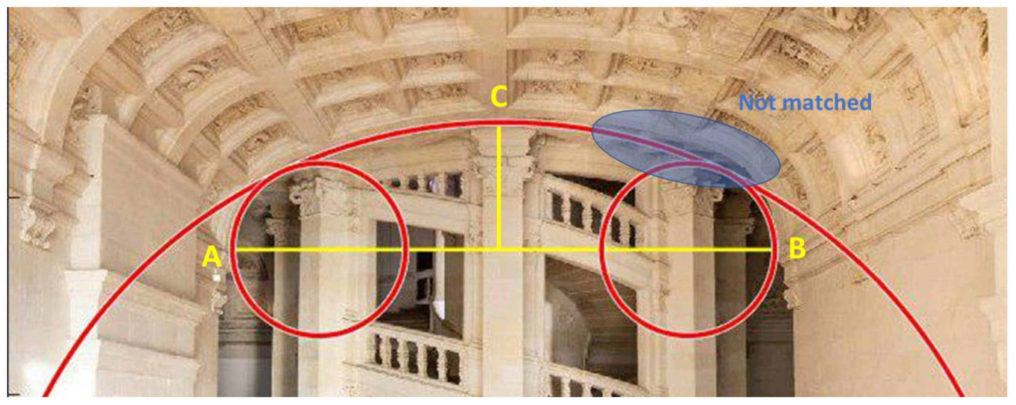
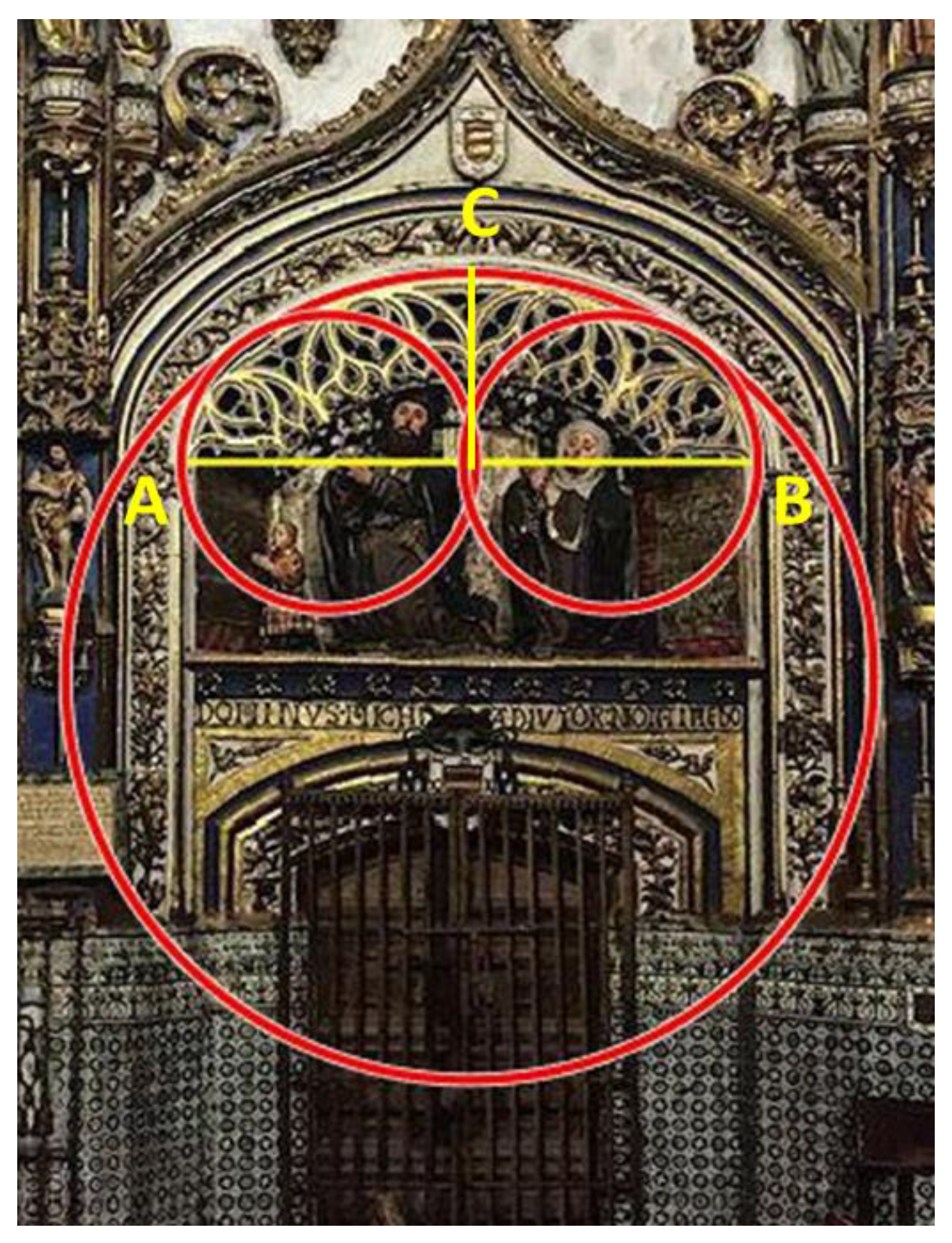
In many of the cases studied, it has been possible to verify first, if they are basket-handle arches of three centers, and second, if the proportion used fulfills the hypothesis raised in this study. It is also necessary to highlight that in those cases in which the solution proposed in this study has not been reached, it has been observed that it is very close. Therefore, it is considered that the study has been valid for arches of this type, basket-handle arches or three centers arches.

7. Conclusions

In this work, the geometry of the basket-handle arch has been reviewed. It has been studied from different approaches. On the one hand, the geometry that is known in classical literature and from the constructive point of view, as a structural element. Since, in a circle, the tangent direction at any point in the circle is perpendicular to the radius passing through that point, it is deduced that the centres of the central arch and of the circles and the point of link or tangency are aligned. The main effort to be considered is the horizontal thrust of the arch, which can be greater, therefore, the greater the relationship between the clear span or the springing line of the arch and the rise. Therefore, raised arches give horizontal thrusts smaller than extended arches. Basket-handle arches are lowered arches that would collapse due to the sinking of the keystone (central piece of the arch) and the overturning of the lower sides towards the outside of the arch. With the increase in the length of the arch span of the basket-handle, the problem of the spatial stability of the arch becomes even more important. Among the infinite solutions, it has been proposed that the optimum solution is an arch as low as possible and that it maintains the aesthetic characteristics. That is to say that of all the possible basket-handle arches, it is the one in which the ratio between the radii (R/r) is the smallest. This study can serve as a basis for the design of basket-handle arches as structural elements maintaining their aesthetic function, which has been used uninterruptedly for centuries.

Author Contributions

A.A., C.V., C.S.-A.-G., A.P.-F., A.P.-R. and F.M.-A. conceived, designed the search and wrote the manuscript.

Funding

This research received no external funding.

Acknowledgments

The authors would like to thank to the CIAIMBITAL (University of Almeria, CeiA3) for its support.

Conflicts of Interest

The authors declare no conflicts of interest

References

  1. Kimball, F.; Edgell, G.H. A History of Architecture; Harper & Brothers: New York, NY, USA, 1918. [Google Scholar]
  2. Cowan, H.J. A history of masonry and concrete domes in building construction. Build. Environ. 1977, 12, 1–24. [Google Scholar] [CrossRef]
  3. DeLaine, J. Structural experimentation: The lintel arch, corbel and tie in western Roman architecture. World Archaeol. 1990, 21, 407–424. [Google Scholar] [CrossRef]
  4. Joshi, A.M.; Deshmukh, A.M. Quality of space in Romanesque and Gothic Architecture. Int. J. Eng. Res. 2018, 7, 160–164. [Google Scholar] [CrossRef]
  5. Lengyel, G. Minimum thickness of the gothic arch. Arch. Appl. Mech. 2018, 88, 769–788. [Google Scholar] [CrossRef]
  6. Calvo-López, J. From Mediaeval Stonecutting to Projective Geometry. Nexus Netw. J. 2011, 13, 503–533. [Google Scholar] [CrossRef]
  7. Campisi, T.; Saeli, M. Taking inspiration from nature: Rules and procedures for a good building practice. In ARCHDESIGN’16-III International Architectural Design Conference on Design and Nature; DAKAM Publishing: Istanbul, Turkey, 2016; pp. 4–17. [Google Scholar]
  8. Ural, A.; Oruç, Ş.; Doğangün, A.; Tuluk, Ö.İ. Turkish historical arch bridges and their deteriorations and failures. Eng. Fail. Anal. 2008, 15, 43–53. [Google Scholar] [CrossRef]
  9. Campisi, T.; Saeli, M. Structural Uses of Stone and Timber in The European Historical Construction. J. World Archit. 2018, 2, 1–11. [Google Scholar]
  10. Saeli, M. Mixed Stone-timber Masonry in Traditional Construction: Structural, Architectural and Anti-seismic Features across Europe. J. Archit. Res. Dev. 2018, 2. [Google Scholar] [CrossRef]
  11. Byne, A.; Byne, M.S. Spanish Architecture of the Sixteenth Century: General View of the Plateresque and Herrera Styles; No. 109; GP Putnam’s Sons: New York, NY, USA, 1917. [Google Scholar]
  12. Jennings, N. Converso Patronage, Self-Fashioning, and Late-Gothic Art and Architecture in 15th-Century Castile. In Jews and Muslims Made Visible in Christian Iberia and Beyond, 14th to 18th Centuries; Brill: Leiden, The Netherlands, 2019; pp. 161–186. [Google Scholar]
  13. Rubiò Bellver, J. Dificultats per Arribar a la Síntessis Arquitectònica; Anuario de la Asociación de Arquitectos de Cataluña: Barcelona, Spain, 1913; pp. 63–79. [Google Scholar]
  14. Heyman, J. Beauvais cathedral. Trans. Newcom. Soc. 1967, 40, 15–35. [Google Scholar] [CrossRef]
  15. Huerta, S. Mecánica de las bóvedas de fábrica: El enfoque del equilibrio. Inf. Construcción 2005, 56, 73–89. [Google Scholar] [CrossRef]
  16. Huerta Fernández, S. Arcos, Bóvedas y Cúpulas. Geometría y Equilibrio en el Cálculo Tradicional de Estructuras de fábricaArcos, Bóvedas y Cúpulas. Geometría y Equilibrio en el Cálculo Tradicional de Estructuras de Fábrica; Instituto Juan de Herrera: Madrid, Spain, 2004. [Google Scholar]
  17. Moseley, H.L. On a new principle in statics, called the Principle of least Pressure. Lond. Edinb. Dublin Philos. Mag. J. Sci. 1833, 3, 285–288. [Google Scholar] [CrossRef]
  18. Block, P.; DeJong, M.; Ochsendorf, J. As hangs the flexible line: Equilibrium of masonry arches. Nexus Netw. J. 2006, 8, 13–24. [Google Scholar] [CrossRef]
  19. Ricci, E.; Fraddosio, A.; Piccioni, M.D.; Sacco, E. A new numerical approach for determining optimal thrust curves of masonry arches. Eur. J. Mech. A/Solids 2019, 75, 426–442. [Google Scholar] [CrossRef]
  20. Alexakis, H.; Makris, N. Limit equilibrium analysis and the minimum thickness of circular masonry arches to withstand lateral inertial loading. Arch. Appl. Mech. 2014, 84, 757–772. [Google Scholar] [CrossRef]
  21. Alexakis, H.; Makris, N. Limit equilibrium analysis of masonry arches. Arch. Appl. Mech. 2015, 85, 1363–1381. [Google Scholar] [CrossRef]
  22. Tempesta, G.; Galassi, S. Safety evaluation of masonry arches. A numerical procedure based on the thrust line closest to the geometrical axis. Int. J. Mech. Sci. 2019, 155, 206–221. [Google Scholar] [CrossRef]
  23. Velilla, C.; Alcayde, A.; San-Antonio-Gómez, C.; Montoya, F.G.; Zavala, I.; Manzano-Agugliaro, F. Rampant Arch and Its Optimum Geometrical Generation. Symmetry 2019, 11, 627. [Google Scholar] [CrossRef]
  24. Milankovitch, M. Theorie der Druckkurven. Z. Math. Phys. 1907, 55, 1–27. [Google Scholar]
  25. Heyman, J. The safety of masonry arches. Int. J. Mech. Sci. 1969, 11, 363–385. [Google Scholar] [CrossRef]
  26. Alexakis, H.; Makris, N. Minimum thickness of elliptical masonry arches. Acta Mech. 2013, 224, 2977–2991. [Google Scholar] [CrossRef]
  27. Boothby, T.E. Analysis of masonry arches and vaults. Prog. Struct. Eng. Mater. 2001, 3, 246–256. [Google Scholar] [CrossRef]
  28. Gómez-Collado, M.C.; Roselló, V.C.; Tamborero, E.C. Mathematical modeling of oval arches. A study of the George V and Neuilly Bridges. J. Cult. Herit. 2018, 32, 144–155. [Google Scholar] [CrossRef]
  29. Casado, E.A.; Sánchez, J.M.D. Geometría del arco carpanel. Suma Rev. Sobre Enseñanza Aprendiz. Matemáticas 2015, 79, 17–25. [Google Scholar]
  30. San-Antonio-Gómez, C.; Velilla, C.; Manzano-Agugliaro, F. Photogrammetric techniques and surveying applied to historical map analysis. Surv. Rev. 2015, 47, 115–128. [Google Scholar] [CrossRef]
  31. Al-Omari, A.; Beck, K.; Brunetaud, X.; Török, Á.; Al-Mukhtar, M. Critical degree of saturation: A control factor of freeze–thaw damage of porous limestones at Castle of Chambord, France. Eng. Geol. 2015, 185, 71–80. [Google Scholar] [CrossRef]
  32. Janvier-Badosa, S.; Beck, K.; Brunetaud, X.; Al-Mukhtar, M. Historical study of Chambord castle: A basis for establishing the health record of the monument. Int. J. Archit. Herit. 2013, 7, 247–260. [Google Scholar] [CrossRef]
  33. Janvier-Badosa, S.; Beck, K.; Brunetaud, X.; Al-Mukhtar, M. The occurrence of gypsum in the scaling of stones at the Castle of Chambord (France). Environ. Earth Sci. 2014, 71, 4751–4759. [Google Scholar] [CrossRef]
  34. Al-Omari, A.; Brunetaud, X.; Beck, K.; Al-Mukhtar, M. Effect of thermal stress, condensation and freezing–thawing action on the degradation of stones on the Castle of Chambord, France. Environ. Earth Sci. 2014, 71, 3977–3989. [Google Scholar] [CrossRef]
  35. Colding, T.H.; Minicozzi, W.P., II. Disks that are double spiral staircases. Not. AMS 2003, 50, 327–339. [Google Scholar]
  36. Tanaka, H. Leonardo da Vinci, architect of Chambord? Artibus Hist. 1992, 13, 85–102. [Google Scholar] [CrossRef]
  37. Dushkina, N. Russia: 20th-Century Heritage. Heritage at Risk. 2003, pp. 177–181. Available online: https://journals.ub.uni-heidelberg.de/index.php/heritage/article/download/21204/14973 (accessed on 14 August 2019).
  38. Gerin, A. Stories from Mayakovskaya Metro Station: The Production/Consumption of Stalinist Monumental Space, 1938. Ph.D. Thesis, University of Leeds, Leeds, UK, 2000. Available online: http://etheses.whiterose.ac.uk/6749/1/424660.pdf (accessed on 14 August 2019).
  39. Shilin, A.A.; Kirilenko, A.M.; Znajchenko, P.A. Complex reconstruction project of Mayakovskaya metro station in the centre of Moscow. In Structural Analysis of Historical Constructions—Anamnesis, Diagnosis, Therapy, Controls; Van Balen, K., Verstrynge, E., Eds.; Taylor & Francis Group: London, UK, 2016; pp. 1736–1741. ISBN 978-1-138-02951-4. Available online: http://znayugeo.ru/wp-content/uploads/2016/11/ch234.pdf (accessed on 14 August 2019).
Figure 1. The main arch types used in architecture. (A) Semicircular. (B) Stilted. (C) Segmental. (D) Basket-handle or three-centered. (E) Rampant. (F) Three pointed or Gothic. (G) Acute. (H) Depressed. (I) Keyhole. (J) Ogee three-centered. (K) Ogee four-centered. (L) Oriental. (M) Round Trefoil. (N) Draped. (O) Parabolic.
Symmetry 11 01243 g001
Figure 2. (A) Basket-handle arch. (B) Basket-handle arch resulting from half an oval.
Symmetry 11 01243 g002
Figure 3. Basket-handle arches in Spain. (A) University of Alcala. (B) University of Salamanca.
Symmetry 11 01243 g003
Figure 4. Basket-handle arches in France. (A) Rodez Cathedral. (B) Gateway to the Château de Chenonceau.
Symmetry 11 01243 g004
Figure 5. Basket-handle arch integrated with the ogee or inflected arch of the gate of Monasteries in Spain. (A) Monastery of San Antonio el Real in Segovia. (B) Monastery of Santa Clara in Palencia.
Symmetry 11 01243 g005
Figure 6. (A) Basket-handle arch of one of the galleries of the Blenheim Palace (UK). (B) Basket-handle arch of the central nave of the Metropolitan Cathedral of Mexico City.
Symmetry 11 01243 g006
Figure 7. Basket-handle arches on brick cores of the arcades of the Plaza de España in Seville (Spain).
Symmetry 11 01243 g007
Figure 8. Examples of modernist basket-handle arches.
Symmetry 11 01243 g008
Figure 9. Basket-handle arch elements: (1) Keystone, (2) Voussoir, (3) Impost, (4) Intrados, (5) Rise or sagita, (6) Clear span or springing line. (7) Abutment, (8) Springer. Red dashed line- Lower thrust line. Blue dashed line- Upper thrust line.
Symmetry 11 01243 g009
Figure 10. Basket-handle arch of three arches graphically constructed. (A) Known A and B (method 1). (B) Known A, B and C (method 2).
Symmetry 11 01243 g010
Figure 11. Example of several basket-handle arches for a specific clear span (A-B), and the arch proposed.
Symmetry 11 01243 g011
Figure 12. Graphical geometric construction of the basket-handle arch proposed.
Symmetry 11 01243 g012
Figure 13. Flow chart of the software for optimal basket-handle arch calculation.
Symmetry 11 01243 g013
Figure 14. Calculation of the optimal basket-handle arch (in red) over the room giving access to the helicoidal staircase of the Château de Chambord.
Symmetry 11 01243 g014
Figure 15. Calculation of the optimal basket-handle arch (in red) over the Plaza de España of Vitoria (Spain).
Symmetry 11 01243 g015
Figure 16. Calculation of the optimal basket-handle arch (in red) over the Chapel of All Saints or Golden Chapel in Salamanca Cathedral (Spain).
Symmetry 11 01243 g016
Figure 17. Moscow subway station (Mayakovskaya). (A) Original image. (B) Analysis of the optimal basket-handle arch (in red).
Symmetry 11 01243 g017

