The Hay Inclined Plane in Coalbrookdale (Shropshire, England): Geometric Modeling and Virtual Reconstruction


1
Department of Engineering Graphics, Design and Projects, University of Jaén, Campus de las Lagunillas, s/n, 23071 Jaén, Spain
2
Research Group ‘Engineering Graphics and Industrial Archaeology’, University of Jaén, Campus de las Lagunillas, s/n, 23071 Jaén, Spain
*
Author to whom correspondence should be addressed.
Symmetry 2019, 11(4), 589; https://0-doi-org.brum.beds.ac.uk/10.3390/sym11040589
Submission received: 9 April 2019
/
Revised: 19 April 2019
/
Accepted: 22 April 2019
/
Published: 24 April 2019
(This article belongs to the Special Issue Symmetry in Engineering Sciences)
Abstract
:This article shows the geometric modeling and virtual reconstruction of the inclined plane of Coalbrookdale (Shropshire, England) that was in operation from 1792 to 1894. This historical invention, work of the Englishman William Reynolds, allowed the transportation of boats through channels located at different levels. Autodesk Inventor Professional software has been used to obtain the 3D CAD model of this historical invention and its geometric documentation. The material for the research is available on the website of the Betancourt Project of the Canary Orotava Foundation for the History of Science. Also, because the single sheet does not have a scale, it has been necessary to adopt a graphic scale so that the dimensions of the different elements are coherent. Furthermore, it has been necessary to establish some dimensional, geometric, and movement restrictions (degrees of freedom) so that the set will work properly. One of the main conclusions is that William Reynolds designed a mechanism seeking a longitudinal symmetry so that, from a single continuous movement, the mechanism allows two vessels to ascend and descend simultaneously. This engineering solution facilitated a doubling of the working capacity of the device, as well as a reduction of the energy needs of the system.
1. Introduction
The present study is part of the research line of industrial archeology whose purpose is the systematic study of the industrial memory of an era. Addressing industrial archaeology from the point of view of engineering provides a necessary vision for the correct understanding of industrial heritage, since in many occasions this study is carried out in an unscientific way, and the written record of said heritage being incomplete and with the consequent risk of loss.
The work presented in this article has been developed within a research project on the work of an outstanding Spanish Enlightenment engineer, Agustín de Betancourt, and Molina [1,2], analyzing his best known inventions from an engineering graphics standpoint in order to obtain his geometric modeling [3,4,5].
As is well known, a first step for the recovery and study of industrial heritage is the creation of realistic 3D CAD models. The article shows the 3D digital restitution of the inclined plane for the transport of vessels that operated in Coalbrookdale (Shropshire, England) at the end of the 18th century. This 3D model has been obtained with CAD (computer-aided design) techniques on which we carry out subsequent CAE (computer-aided engineering) studies, following the objectives established in the document Principles of Seville [6] on virtual archaeology that cites the London Charter [7] regarding the computer-based visualization of cultural heritage.
The Shropshire canal was created in 1790 and closed to river traffic in 1944. Its construction allowed the channeling of one of the mining regions of the County of Shropshire through several minor canals that connected the Union Shropshire Canal to the north with the population of Coalbrookdale to the south, along the River Severn [8,9].
Initially, the project consisted of the creation of a fluvial transport network in a difficult region to channel due to its geography, but with a high economic interest due to the presence of factories and coal mines. His main promoter was William Reynolds who already had some experience personally planning the Ketley channel. To solve the problem of level differences, Reynolds used a novel solution for the channels of the time, the use of dry inclined planes by which to transport the boats through channels at different levels [10]. The first channel in England in which this technique was used was that of Ketley (1788), and based on this first experience, Reynolds himself designed the inclined plane of Coalbrookdale, popularly known as ‘The Hay inclined plane’ [11].
This inclined plane was launched in 1792, saved a drop of 207 feet (63.1 m), and had a length of 350 yards (320 m), which supposed a ramp of 11.15 sexagesimal degrees (slope of 19.71%). The inclined plane of Coalbrookdale differs from that of Ketley in that at the top, it does not end in a lock. Also, it was a bidirectional channel that allowed for ascending and descending boats at the same time. The upper part of the inclined plane rose a few meters above the level of the upper channel, and from this point descended another much shorter inclined plane that connected with the upper channel [12].
The inclined plane was a considerable benefit for the coal mines and smithies of the area, enabling the trade of their products through the River Severn to countless destinations, and the river port Coalport became an industrial hub of the first magnitude [13].
During his stay in England (1793–1796), Agustín de Betancourt devoted an important part of his time to the study of navigation channels [1]. This is what is recorded in his work ‘Mémoire sur un nouveau système de navigation intérieure’ written in Paris many years later (1807) [14]. One advantage of this stay was the acquisition of knowledge of the inclined plane of Coalbrookdale, which allowed saving a huge drop without loss of water in the process of the ascent and descent of boats. Specifically, Agustín de Betancourt copied in detail the mechanism as it had been built by businessman William Reynolds and engineer John Lowden, drawing a colored sheet of the inclined plane with much detail and a handwritten memory of three pages explaining the parts of the plane and its functioning. These are the only documents that arrived in Paris in reference to the inclined plane of Coalbrookdale [15]. A few months after the development of this memory, the French engineer François de Recicourt wrote a short report explaining the use that the English gave of the inclined plane to overcome considerable level differences in their channels. In this memory, he mentions the drawings of the inclined plane donated by Robert Fulton [16] and other American authors to the French Academy of Sciences, and in the final part of the document, there is an explanatory sheet signed by Betancourt. This sheet is a scheme based on his own drawing, which includes explanations for the understanding of its operation [17].
Almost three decades later, in 1807, Betancourt wrote his work on a new interior navigation system [14]. This report proposes a channel navigation system for France very similar to the English navigation system: Shallow channels and an advanced system of locks that avoids the loss of water in the ascent and descent of the boats. The report proposes a new lock system consisting of a plunger that pushes water from a reservoir and locally increases the water level of the channel, allowing the ascent and descent of these vessels. In that memory, Betancourt applies his plunger lock to the inclined plane and mentions Robert Fulton’s previous work [16], indicating that his inclined plane is designed according to the Reynolds procedure. To overcome differences of over 5 m, Betancourt proposes using a series of locks or the use of an inclined plane. This is where he refers again to the inclined plane of Coalbrookdale, although modifying some elements of the same and adding to the system his plunger lock, in order to flood the boat zone of the upper channel. The inclined plane of Betancourt has no descent ramp, unlike that of Reynolds, so the ascent ramp ends at the level of the upper channel. Of this modification of the inclined plane of Coalbrookdale there are two color plates (and a more modern version based on the original one), as well as the explanatory texts of the memory that Betancourt presented to the Academy of Sciences of Paris [14].
At present, of the Coalbrookdale inclined plane, only the ruins remain and some vintage photographs taken from a distance and kept at the Coalbrookdale Museum of Iron located in Shropshire (England) [18], which still show the inclined plane and the remains of the tracks, although it is also possible to distinguish the upper cargo basin and the remains of the brick factory of the building that housed the steam engine. Some photographs taken of the Hay inclined plane show its condition in various years from 1879 to 2012 [19].
The main objective of this research is to obtain a reliable 3D CAD model of this historical invention that allows us to know, in detail, this outstanding engineering work that significantly influenced the socioeconomic development of the region, and which will enable future studies of computer-aided engineering. The originality and novelty of this research is that there is no 3D CAD model of this historical invention with this degree of detail, helping in an outstanding way in the detailed understanding of its operation. An educational goal is also pursued, through its exhibition on the websites of the foundations that have supported this research (Fundación Canaria Orotava de Historia de la Ciencia [20] and Fundación Agustín de Betancourt [21]), as well as in other museums of the history of technology.
The remainder of the paper is structured as follows: Section 2 presents the materials and methods used in this investigation; then, Section 3 includes the main results in the process of geometric modeling and their discussion to explain the operation of this device (both in the ascending and descending movement), and Section 4 shows the main conclusions.
2. Materials and Methods
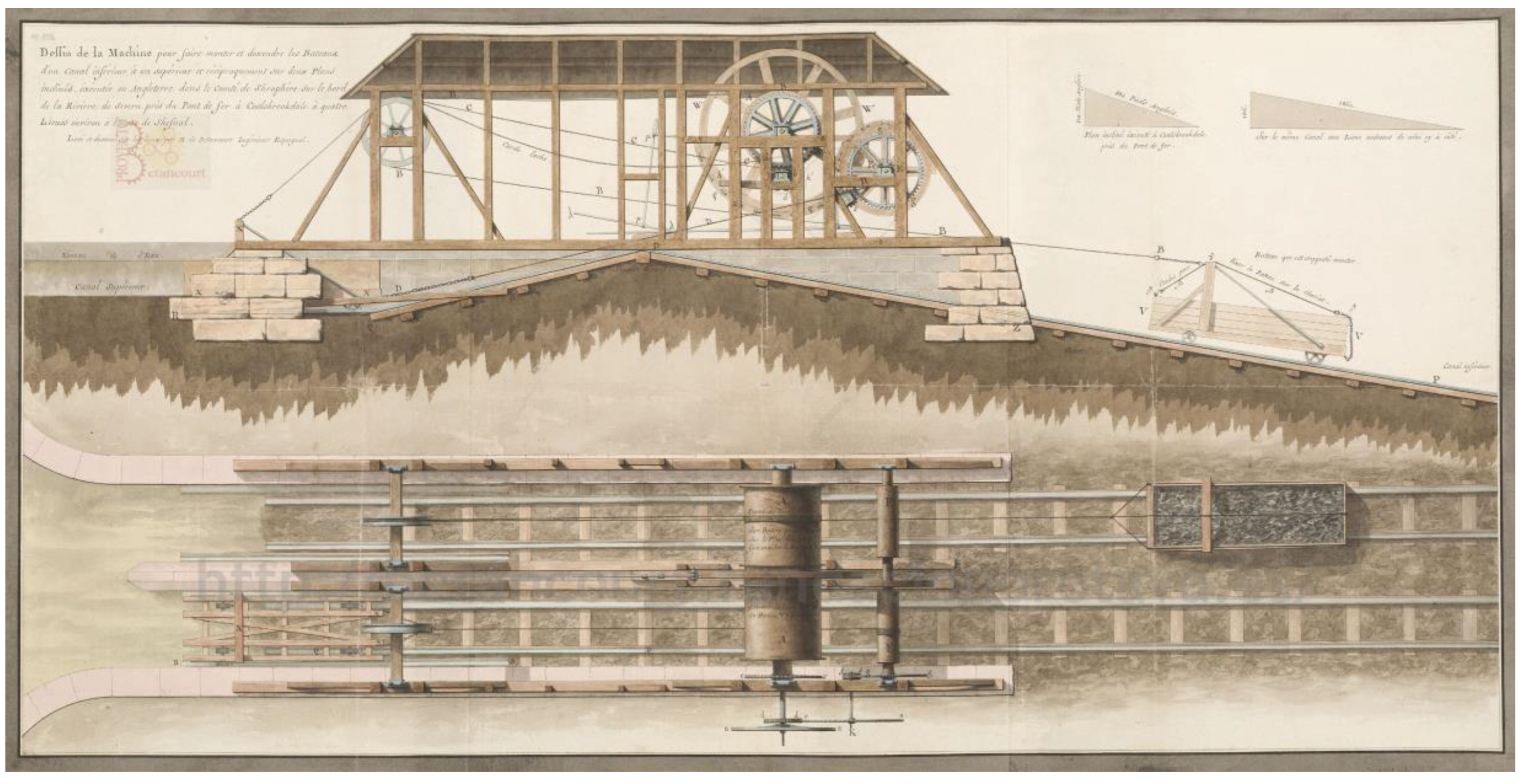
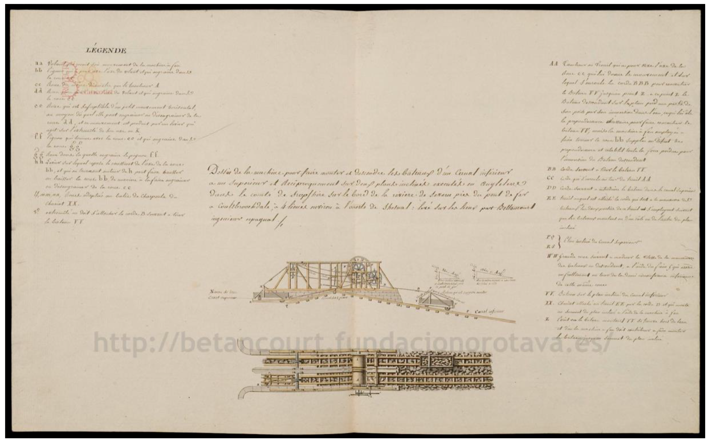
The material used in this research was obtained from two files on the Betancourt Digital Project website of the Canary Orotava Foundation for the History of Science [22], assigned for its digitalization by the National School of Bridges and Roads of ParisTech University. The first of these is manuscript 1558 (MS 1558), consisting of a descriptive memory of 3 pages and a sheet (Figure 1) made by Betancourt [15], and the second is the manuscript 2812 (MS 2812) of Recicourt that contains several documents, one of which is an explanatory sheet of the Hay inclined plane (Figure 2) [17].
The graphic legacy that exists on the inclined plane of Reynolds is valuable but scarce, and does not provide the information that today would be expected from a descriptive plane of a mechanism. Specifically, the sheet printed in A3 format from which the dimensions of the elements have been taken by direct measurement does not have a graphic scale (Figure 1), but only the dimensions of the ramps that make up the gap to be saved. Therefore, there is no direct reference that can be used to obtain an accurate graphic scale of the sheet, nor does it exist in the descriptive memory. As in other documents of the time, they are not plans made with the level of detail of a contemporary plan, but rather a descriptive model that seeks only to facilitate understanding of the operation of the mechanism.
To alleviate in part the lack of information, the research is based on the industrial remains of the current inclined plane, such as the lower access channel to the inclined plane, the tracks on the inclined plane, the stone factory on which the wooden structure sat, the short upper plane, and the upper channel. There are also the ruins of a building that housed a steam engine with a chimney. Therefore, these industrial remains [19] have been used to check the actual dimensions of the different elements of the inclined plane in order to find a real scale of the Agustín de Betancourt plate (Figure 1), and in turn, they also serve to confirm that all the elements that appear in this sheet correspond to the signals that can be seen in the industrial remains.
In order to obtain a 3D reconstruction that represents a functional set, it is very important to understand the workings of the mechanism and what each of its elements are for. As happens with a great number of inventions of the time, the two dihedral projections of the sheet (front view and top view) are insufficient to obtain information of all the elements, which has forced us to establish different conjectures and/or proposals that have had to be validated when compared with other mechanisms of the time. In addition, it has been necessary to incorporate knowledge of mechanical engineering in order to geometrically model some elements, since each one of them had to have its specific mission in the set. This task has been one of the most complicated, since there is no information in the file of many of the elements.
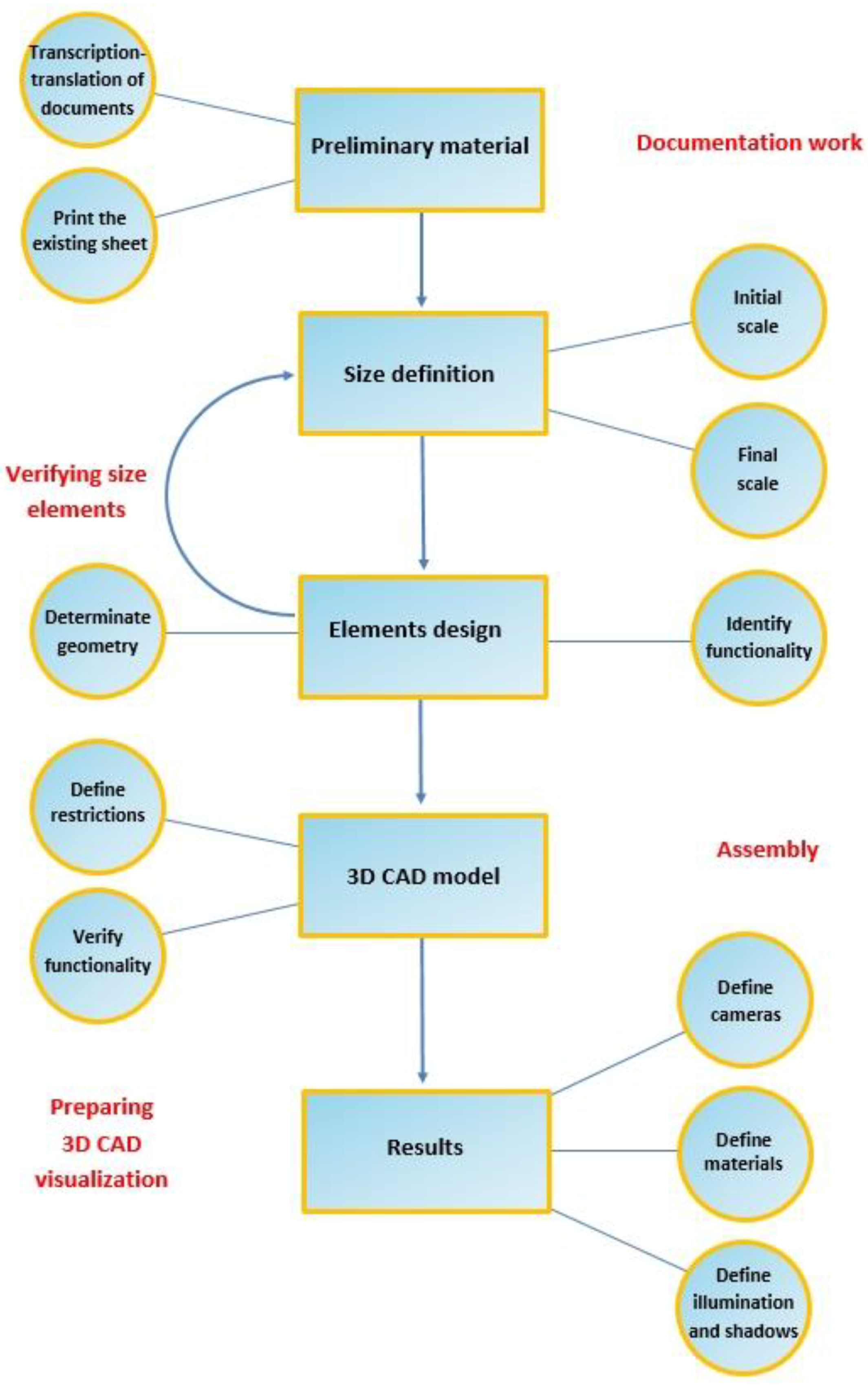
The methodology followed in the 3D modeling of the device of William Reynolds consists of the following steps:
1. Transcription and translation of the notes of Agustín de Betancourt
In order to fully understand the functioning of William Reynolds’ device, it is not enough to analyze the only sheet with the graphic representation that Agustin de Betancourt made of the inclined plane [15], but it is necessary to translate the three-page handwritten memory in French and dated in 1796 where the different parts of it and its operation are explained. Here, the main elements are detailed, accompanied by an alphabetic reference and the function that each element performs.
2. Proportional impression of the existing sheet depicting the inclined plane of Coalbrookdale
Once the file MS 1558 (descriptive memory of 3 pages and an explanatory sheet (Figure 1)) of the website of the Betancourt Digital Project [22] had been downloaded, the sheet was printed in color, keeping the proportionality of the image on a format of A3 paper, in order to be able to directly measure the dimensions of all the elements.
3. Determination of the general scale of the sheet and verification with the existing remains
Given that the sheet does not have a graphic scale, and that there is no related information in the descriptive memory, it is necessary to determine the scale thereof for the correct 3D CAD modeling of the invention. It is therefore essential to determine a known reference dimension, which in this investigation has been the width of the trailer as this was standardized throughout the county of Shropshire.
It is known that Shropshire was a county where mining had a special relevance, and Coalbrookdale specifically was the epicenter of the industrial revolution, with the cars for the extraction of coal being what determined the width of the roads. According to the English engineer George Stephenson, before 1832, the track width was 4 feet and 8 inches (1.422 m). Later, this engineer extended the width of the tracks by half an inch more for the construction of the Liverpool-Manchester railway, and since then this measure has been the most widely used in most of the railways of the world [23].
Therefore, the measure of reference adopted in this investigation to determine the scale of the sheet has been the track width with a value of 1.422 m. Thus, if the width of the A3 printed sheet is measured, it results in a value of 12.5 mm, so that the approximate scale of said sheet turns out to be 11: 1250; that is, a value of around 1: 113, which, as a first approximation, is enough to give some idea of the proportions of the different elements.
However, it is necessary to check dimensionally that the general scale we have determined is correct. Agustín de Betancourt detailed in his sheet particularities of the foundation of the structure, which allows us to compare the current dimensions of the ruins with the 3D model.
The walls on which the wooden structure rests on the Betancourt plate from which the dimensions have been taken correspond, without any doubt, to the walls that currently exist [19]. The successive reforms that the mechanism had to undergo, especially in its materials, did not affect the stone factory of the canal that has remained to this day. Thus, the width of the channel between the walls is 7 feet and 10 inches (approximately 2.387 m), but in the model the width is 2.370 m, so the difference between one and another is 17 mm.
Taking into account that the measures have been taken with a caliber with an error of 0.1 mm and applying the scale 11: 1250, the error attributable to the caliber is +/- 11.36 mm. Therefore, it was not necessary to adjust the scale for the precision that can be requested at the level of detail of the plane, which confirms that the scale chosen is correct.
Undoubtedly, the existence of industrial remains (called ‘material culture’ in the discipline of industrial archeology) has been a great advantage in the process of confirmation and determination of the actual graphic scale of the sheet.
4. Identification of the different systems by their functionality
In this section, the different elements or systems have been defined by their function in the inclined plane based on the determination of their dihedral projections (orthographic views) thanks to the knowledge of the descriptive geometry. These have been:
- Stone factory and canal. This system comprises the immobile part of the inclined plane: The grading, sleepers, tracks, and walls of the upper part that delimit the two accesses to the inclined plane. Its materials are stone, oak wood, and cast iron.
- Support structure. This is the set of elements that serve as structural support to the mechanism for raising and lowering the boats. The frames are all made of oak and on them, the axes will be supported by supports fixed to the structure.
- Traction system (transmission shaft). The traction system consists of the drive axles and pulleys, specifically referring to the four axes that come into play in the process of ascent and descent: The axle with its inertia wheel in contact with the steam engine, an intermediate shaft that serves to change the direction of rotation, and two main axes that are responsible for movement in the long plane and the short plane. In addition to these four axes are also included pulleys that facilitate movement. The axle of the inertia wheel and the intermediate one are made of cast iron, like the pulleys, while the main axes have an iron core, like their gears, but their drums are made of wood like their wheels.
- Braking system. This refers to the brakes that affect the wheels of the two main axes to stop the transmission system. A very functional friction brake system made of wood, driven by bars made of cast iron, and fixed in the frame by metal supports of the same material.
- Trailers-boats. The trailer is the frame of oak wood suspended on six cast iron metal wheels on which the wooden boat rests. Also, in order to provide the boat with stability during the climb, this frame is equipped with several hooks and metal chains.
- Finally, there are the cords that serve as a link between the different systems. The ropes made of hemp fiber are used to join the traction axles with the trailers, and both are traction ropes since they serve for both the ascent and the descent of the boats.
5. Determination of the dimensions and geometry of each element
Once the different systems of the whole of the invention have been identified, the dimensions and geometry of each element defined by its dihedral projections are determined. This step is essential in order to make a model faithful to the original plane. For this, it is important to combine collaborative work with CAD with a consistent and symmetric geometric modeling process [24].
As previously indicated for the direct measurement of each element on the sheet (Figure 1), the aforementioned scale (11: 1250) is applied and modeled with the aid of the parametric software Autodesk Inventor Professional [25], generating a file with extension (.ipt). Similarly, in the design process, each element must be assigned a material with certain physical properties that are essential for the model to be real and not just a geometric approximation.
However, it has been necessary to define a series of elements since, from their position on the sheet (Figure 1), it has not been possible to determine their geometry, perhaps because Betancourt did not want to draw them to give greater clarity to others.
The dihedral projections drawn by Betancourt are partially sectioned, and in addition, there are some elements drawn with some transparency in order to be able to observe the elements that they cover. In the case of the friction braking system, all the brake elements have not been drawn. The braking bars and the inertia wheels of the axes are perfectly observed, but the brake support of the other end at the point on which it is supported is not distinguishable and does not appear in any of the dihedral projections. Since the brake worked by friction, it is understood that this end had to rest on the frame so that it was very close to the inertia wheel of the shaft that was to be braked. Thus, in the case of both brakes, it has been necessary to make an assumption of the geometry and dimensions of this support.
On the other hand, the axle that transmits the movement from the steam engine to the rest of the transmission shaft has the ability to change position and disengage its wheels from the gears it moves. For this, there is a bar on which it rests that can be moved. This bar and its function are described in the descriptive memory, but the illustration does not allow us to appreciate it clearly. Therefore, it has also been necessary to define this bar and its support dimensionally so that it could perform the function for which it was conceived.
6. Assembly of all the elements and obtaining of the 3D CAD model
It is necessary to highlight the importance of the assembly of all the elements being carried out correctly, applying the necessary restrictions (geometric, dimensional, and movement) so that there is a single assembly allowing us to obtain a very complete model that perfectly reflects the mechanical and structural characteristics of the mechanism.
In order to assemble the elements, we have to define the relationship between them, by means of restrictions and unions. The restrictions used allow adjacent elements to define the degrees of freedom they have in their movement, while in the unions, there is no freedom. The correct execution of this process is crucial in order for the model to behave in a realistic manner.
The software used (Autodesk Inventor Professional) has its limitations when it comes to reproducing the relationship between elements, for example the relationship between links in the chain, which is very complicated. The toroidal geometry makes it very difficult to define correctly between surfaces in the contact between two links, and therefore when modeling the link, a pair of points have been defined in the internal region of the link (at the ends of their breasts). Thus, two contiguous links define their relationship by opposing these points, but this definition gives rise to an unreal relationship that can give problems when using the model in a static analysis to obtain the Von Mises stresses, for example.
The relationship of the brake with the axle of inertia of the shaft is also problematic. Depending on the position of the brake rod, it will embrace the inertia wheel to a greater or lesser extent, exerting an unequal frictional force on it. However, the changing behavior of this brake cannot be modeled although there is a direct relationship with the position of the bar. Also, there is no data available on the coefficient of friction of the surfaces that come into contact, so both static and dynamic simulations of the mechanism should take this factor into account.
The rest of the elements (saving those that behave dynamically like the ropes) have been correctly assembled without major difficulty. Thus, once the model is assembled, it could be useful for studying simulations, both dynamic and static, which will allow us to know more about the invention.
7. Preparing 3D CAD model visualization
Obtaining a realistic image of the inclined plane provides valuable information on how the device was during the first years of operation. To obtain these images, the software allows for the use of a digital image editing tool named Autodesk Inventor Studio, which is incorporated as a menu of the main interface. This tool allows us to define a camera from a few simple parameters: Position, framing, angle, and focal length. Once all the parameters of the camera have been defined, the software allows choosing the type of perspective to be taken on the object: Conical (more realistic) or axonometric.
On the other hand, the software defines a specific appearance and texture for each material that can be modified by defining each element. These default values are those obtained from the library of materials, but each user can define new textures and aspects from their own images.
The next step is to define the lighting of the element and the possible shadows it generates. Autodesk Inventor Studio allows us to define lighting in two ways: Generating a lighting environment or defining the position and intensity of lights or spotlights. In the present case, it has been decided to take a simple lighting environment taken from those defined by the same library of the software. Shadows, dependent on the lighting definition, can also be configured through the software. Specifically, the software establishes the ones that the object throws on the ground, the shadows that projects on itself, and those due to the lights defined by the user. This set of parameters help to give realism to the modeled object.
Finally, once the camera, materials, lighting, and shadows have been defined, the parameters of the rendering engine must be defined: The sizes of the output image, the type of file and the most important, the number of iteration time for obtaining the image. The rendering engine develops, from the 3D geometry of the model, the simulation of the physical, and luminous conditions of the invention, obtaining a very realistic image of the model through a complex calculation.
The entire process described above is shown as summative scheme in Figure 3.
3. Results and Discussion
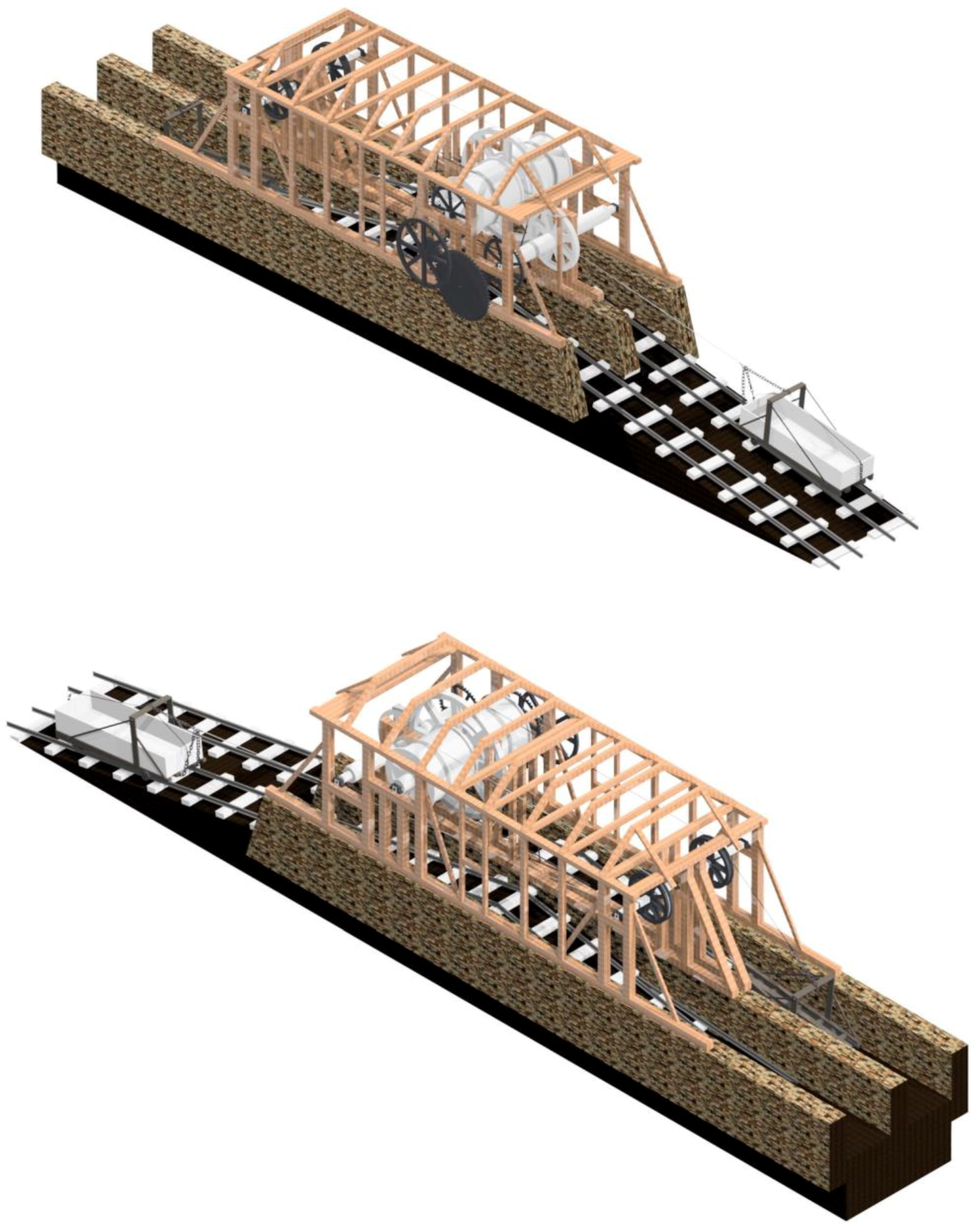
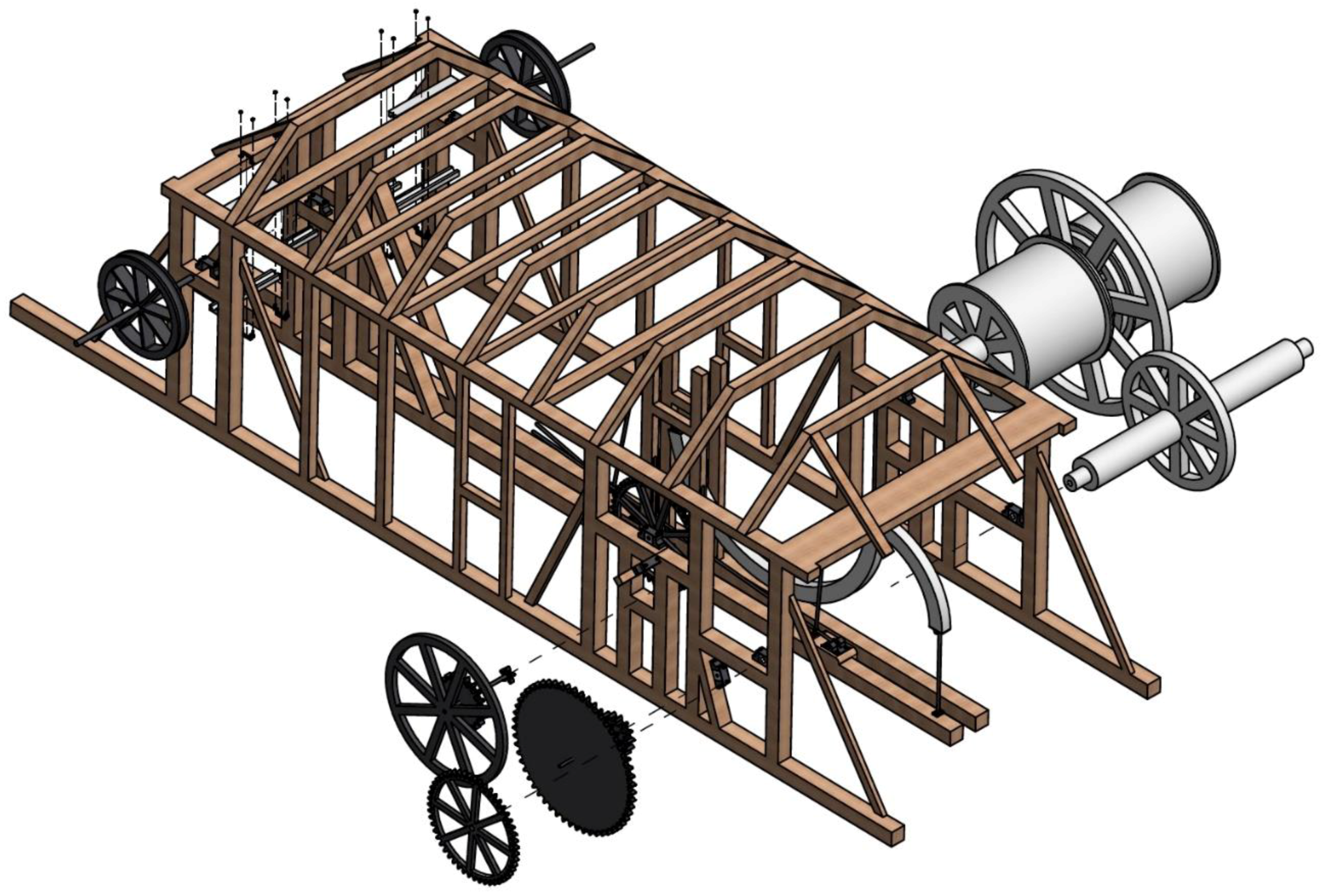
Figure 4 shows a rendered image of the 3D CAD model of the historical invention from one viewing direction and from its opposite, and Figure 5 shows an exploded view of the whole of the device in order to give a better understanding of how the different elements are assembled.
Both figures show the final result of the modeling of the invention after the assembly of all its elements. The isometric views of the inclined plane (Figure 4) are taken from the point of intersection of the three main ortographic views at a sufficient distance to see the ensemble. On the other hand, the exploded view of the model (Figure 5) has been obtained as follows: The first step has been to eliminate the components that are not part of the mechanism: stone factory, tug boats, ropes, tracks, and plane. After this, on this simplified view of the mechanism, the main components (shafts, gears, and pulleys) are separated indicating the direction of extraction. Thus, this view allows a better understanding of the position in which they work and also the visualization of elements that are hidden in the isometric view.
In the process of geometric modeling, the elements with the greatest difficulty were fundamentally the chains and the ropes. The problem with the chains has only an approximate solution, given that links are modeled whose behavior is approximate to that of a real link.
On the other hand, the ropes are not static elements and the software used does not characterize well the physical properties of these elements, neither when they behave under tension nor when they are suspended. For this reason, the ropes are defined as rigid elements of a material similar to hemp fiber, but with a static behavior that does not correspond to the actual behavior of the element.
One of the purposes of the article is the detailed explanation of how the mechanism works in order to understand the complexity of the geometric modeling process.
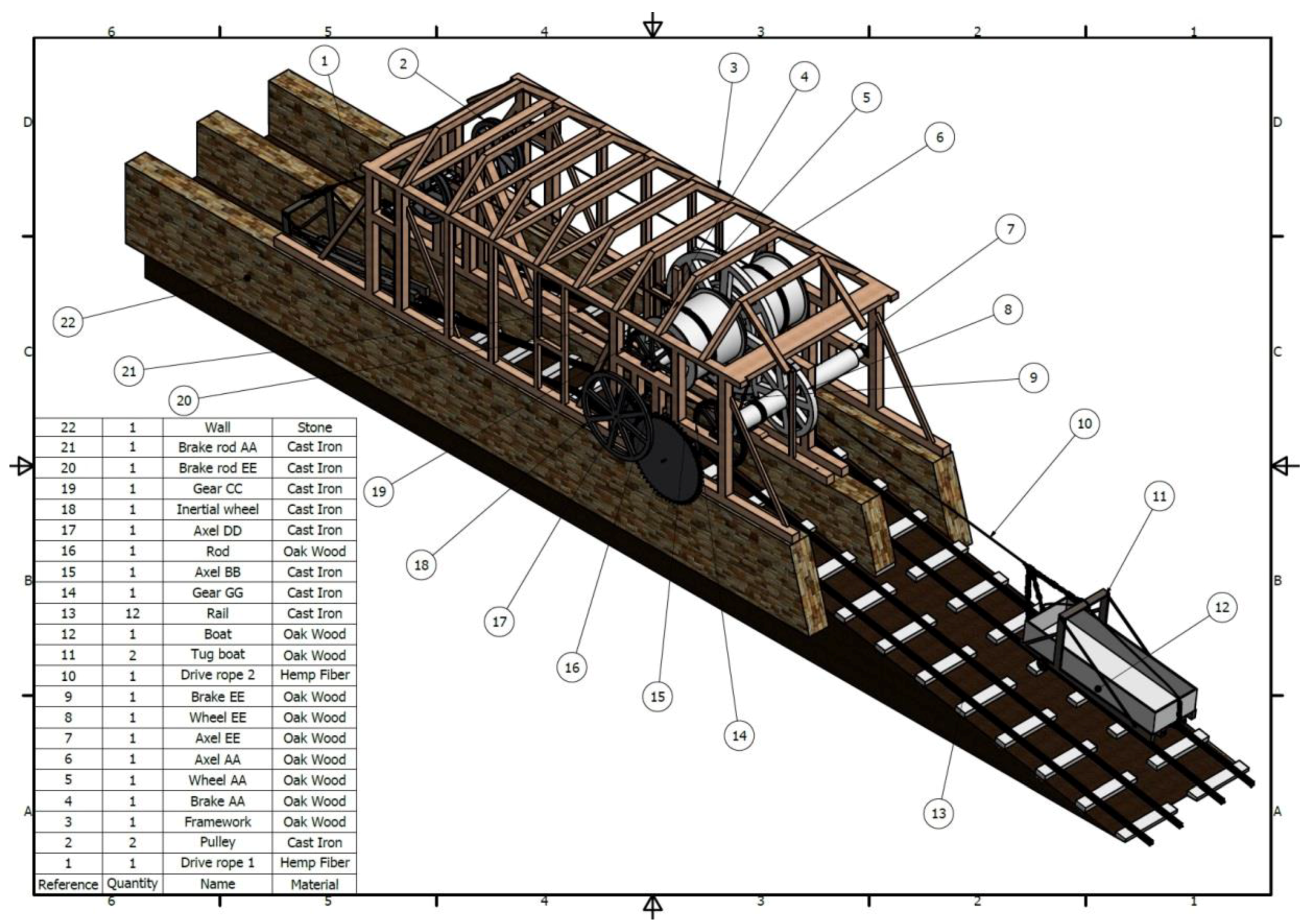
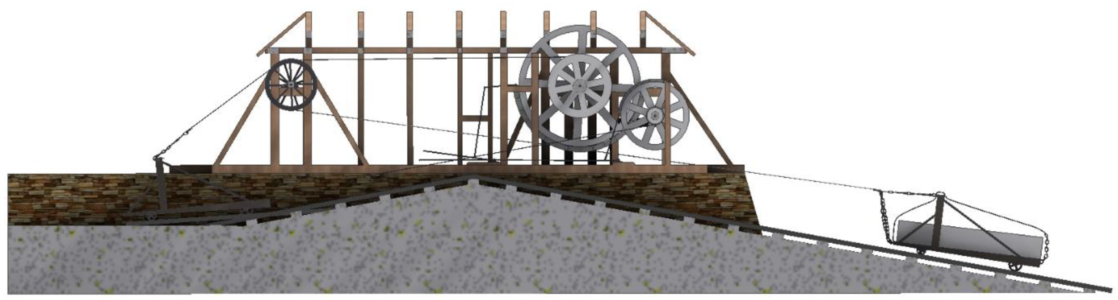
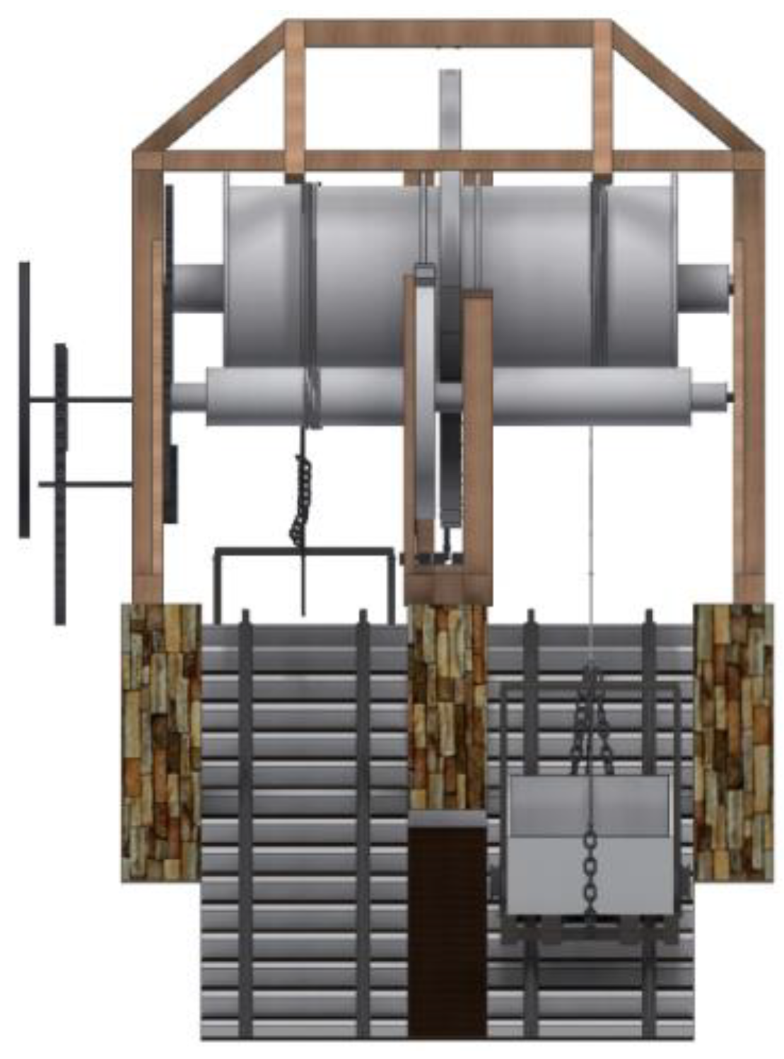
To explain its operation (both in the ascending and descending movement), we will use the plan of the ensemble with an indicative list of the elements and their materials (Figure 6), along with a longitudinal section of the Hay inclined plane (Figure 7) and a profile view of the same to visualize the position and difference of height of the different elements of the mechanism (Figure 8).
3.1. Upward Movement
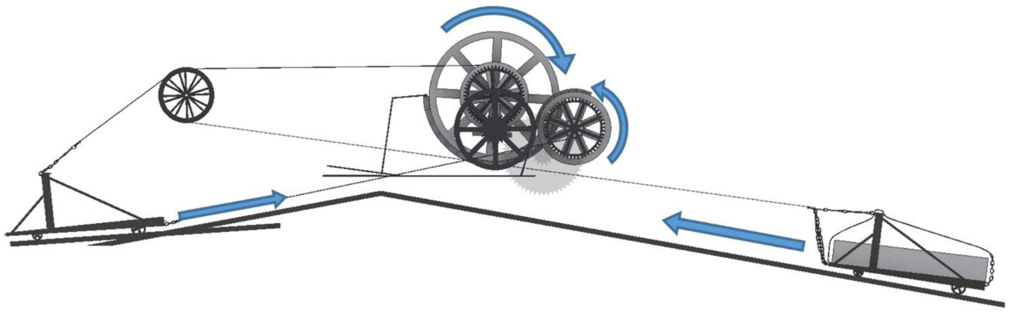
At the bottom of the Hay inclined plane was the loading port on the River Severn (Coalport). Goods were loaded and unloaded at this point of the river and moved from large ships to smaller boats (12) of up to 5 t. These boats navigated the canal to the embouchure of the inclined plane. At this point, an empty tug boat (11) was waiting, which was partially submerged, facilitating the boat´s placement on the trailer. Thus, an operator tied the boat to the trailer with two chains and began the ascension process. The tug boat was a structure of wood and iron supported on six iron wheels. The wheels were designed to facilitate transport by rails (13). Four were aligned on the tracks and two were outside the structure, presenting a function that will be explained later. The tug boat, through a chain, was tied to a drive rope (10) responsible for pulling from the lower area to the upper area of the inclined plane.
The traction rope went from the tug boat to the AA axle (6) through a pulley (2) that facilitated traction. As the AA axle rotated clockwise, the rope coiled and the trailer with the boat climbed the inclined plane. Obviously, this operation required a system of gears and an engine to move it, which is presented below.
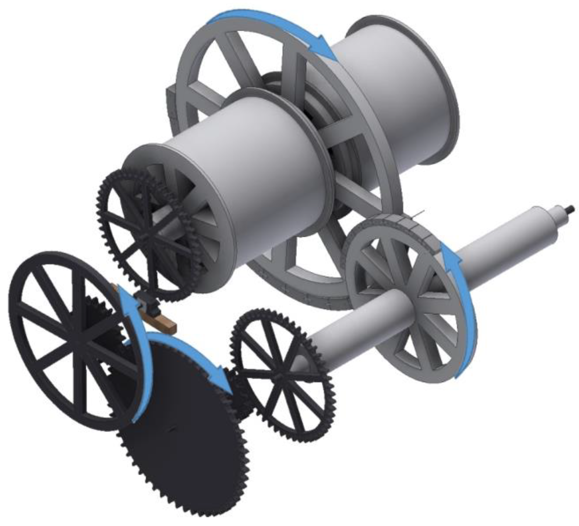
An inertia wheel (18) (called ‘wheel of fire’ by Agustín de Betancourt) was the element responsible for moving the entire mechanism, and was attached to a large steam engine that can be seen in the old photographs of the inclined plane [19], and from which remains the chimney and the foundations of the building that housed it (in ruins). This inertia wheel was solidly connected by means of a DD shaft (17) to two gears, a close one of 20 teeth and a distal one of 5 teeth, which was in turn supported on a bearing joined to a moving wooden rod (16), whose function was to rapidly uncouple the two gears attached to the inertia wheel from the rest of the mechanism. This action caused the immediate stopping of the mechanism in case of accident or breakdown without the need to stop the steam engine.
The axle of inertia DD was coupled to an intermediate shaft BB (15) with two gears, one larger than 56 teeth, coupled to the gear of 20 teeth, and one smaller than 16 teeth, coupled to the gear shaft EE (7).
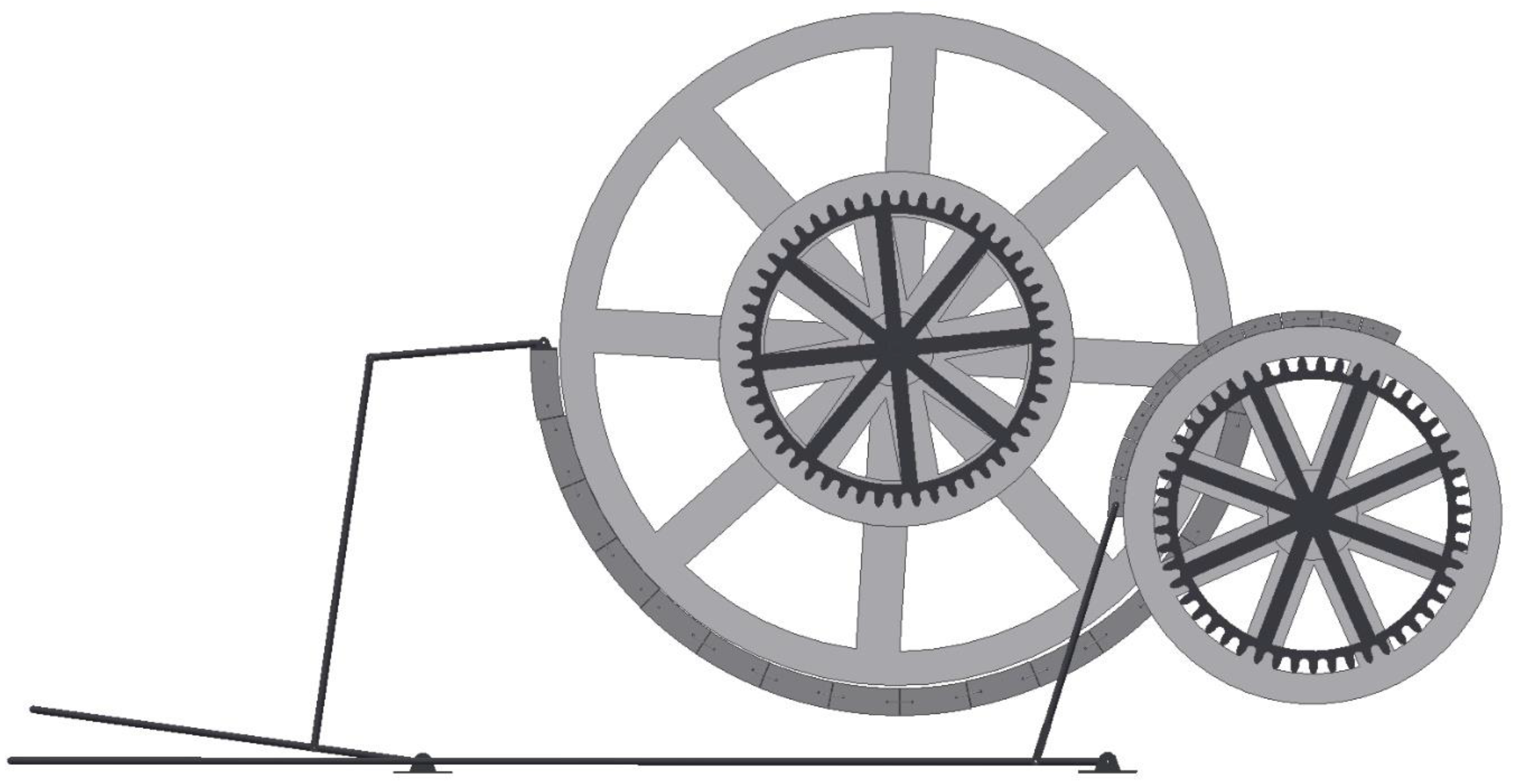
Finally, axes AA and EE were moved by the same wheel AA (5). The AA axle was driven through the coupling of the 5-tooth gear and the 51-tooth DC gear (19) and rotated clockwise (in the opposite direction of the inertia wheel) at a rate of 0.098 turns for each revolution it gave the flywheel of inertia. The EE axle (7), driven through the coupling between the 16-tooth gear of the intermediate shaft and of the GG gear of 51 teeth (14), rotated counter-clockwise (in the direction of the inertia wheel) at the rate of 0.14 turns for each turn that the flywheel made (Figure 9).
As mentioned previously, when the movement was ascending, the traction rope (10) was wound in the form of a coil on the axle AA (6). This axle had the shape of a drum and its diameter measured 2.37 m. Knowing the previously explained relation of teeth, it is easy to calculate that for each turn that the inertia wheel gave the coil collected approximately 0.73 m of rope. The tug boat climbed at that rate to the upper point of the inclined plane. At this point, the rope was disengaged from the trailer and was placed on the upper part, dropping the boat by its own weight onto the short inclined plane that communicated with the upper channel. This inclined plane measured just 10 m and was less steep than the one that ascended from the River Severn ending in a flooded area (upper channel), so there was no need for any braking system to stop it. However, if the merchandise was delicate and the other channel was free the intermediate shaft gear BB (15) could be decoupled, leaving the AA axle (6) without movement. From the intermediate shaft BB, another drive rope (1) could be attached to the chain at the rear of the trailer, allowing the operator to lower the loaded boat to the upper channel by moving the brake bar EE (20) that activated the brake EE (9) on the flywheel (8) of this axle. When descending towards the upper channel, the two unaligned wheels of the trailer, which have been alluded to above, were located on a section of exterior road with less slope, which made the trailer adopt an almost horizontal position facilitating the release of the vessel in the upper channel.
The system was designed to be able to use the two climbing (or descending) routes simultaneously (Figure 10), although the usual way was to use one for ascending and the other for descending.
3.2. Downward Movement
The empty tug boat awaited the arrival of the boat in the upper channel in an almost horizontal position. When this arrived, it was hooked to the trailer and the intermediate shaft gear BB was coupled to give movement to the EE axle. This axle made the trailer ascend with the boat along the short section of the inclined plane to the upper area at a rate of 0.30 m per turn of the inertia wheel. Upon reaching this upper area, it disengaged from the rope (1) and the traction rope (10) disengaged from the upper part and hooked onto the trailer towbar. On the downward hemisphere of the axle AA (6), the rope was wound in the opposite direction to that of the rising hemisphere, and thus, when the drum rotated with axle AA, the rope was wound on one side and unwound on the opposite side. In this way, the load was dropped little by little down the inclined plane to the lower channel.
In this case, the movement of the AA axle could not be disconnected from the movement of the inertia wheel for safety reasons, since this side of the plane had a steep slope and had to be lowered mechanically with great care. In case of failure of the steam engine or due to excessive inertia wheel speed, the AA axle could also be braked by a maneuver of the AA brake rod (21) that operated the AA brake (4) on the wheel (5) of the AA axle (Figure 11). Once the lower channel was reached, the boat was released and continued its itinerary to the loading port on the River Severn.
The inclined plane is an alternative solution to the use of locks to raise and lower vessels from a higher channel to another lower one when the difference in level is very great. However, the mechanism and the maneuvers necessary to carry out the operation of raising or lowering are complex given that many elements intervene.
Among the remarkable features that should be noted of this ingenious device, it is especially relevant its capacity to ascend and descend boats at the same time without interrupting the movement. The mechanism was designed with a longitudinal symmetry that meant that the same ascending movement that wound the rope (10) on the axle AA (6) was the one that facilitated the downward movement of the trailer (11), unrolling the rope of the left hemisphere located on the same AA axle (6). For the successive ascents and descents, it was necessary to alternate the channel of ascent of one hemisphere to the other: When finishing the ascent of a boat by one of the channels, this automatically became the channel of descent, and vice versa. The ingenious mechanism had a longitudinal symmetry that doubled the capacity of transporting goods along the inclined plane.
4. Conclusions
This article shows the complex process followed to obtain the geometric modeling and virtual reconstruction of the Hay inclined plane located in Coalbrookdale (Shropshire, England) as it was originally built, thanks to the parametric software Autodesk Inventor Professional. For this, the investigation has been based on the manuscript notes of Agustín de Betancourt that he took in his visit to the place between 1793 and 1796, shortly after the machine was put into operation by William Reynolds.
The methodology used has been based on knowledge of descriptive geometry and the use of empirical techniques of direct measurement of the dimensions on the printing of the illustrations available from the different sources of information. Also, due to the lack of detailed information it has been necessary to establish a series of geometrical, dimensional, and movement restrictions (degrees of freedom) in order to obtain a coherent and functional 3D CAD model from the point of view of mechanical engineering, which will be the starting point for a future static analysis with CAE techniques.
From this 3D CAD model, it has been possible to obtain the detailed geometric documentation of each of the elements that make up the historical invention, as well as various perspectives such as an isometric view, an exploded perspective, an overall plan with an indication of all the elements of the set and its materials, a longitudinal section, and a profile view, as well as various graphic details, which help to better understand some aspects of its operation (detail of the shaft of transmission and braking system of the drive axles). All this has allowed us to explain easily and in detail the maneuvers of ascent and descent of the boats on the inclined plane.
Thus, this historical invention was a considerable industrial advance in the economy of the area, because thanks to the help of a simple steam engine, the mechanism designed by William Reynolds was used to raise a boat of 5 tons by a difference of 207 feet in only 6 minutes. This supposed much less work than that necessary to unload the cargo in the port of the River Severn and transport it by wagons and horsepower to Coalbrookdale.
Furthermore, a rigorous analysis of his ingenuity has shown that William Reynolds designed a mechanism seeking a longitudinal symmetry whereby, from a single continuous movement, the mechanism would allow two vessels to ascend and descend simultaneously. This engineering solution helped double the working capacity of the device and even reduce the energy needs of the system.
The influence that the design of the inclined plane had on two of William Reynolds’ contemporaries, Agustín de Betancourt and Robert Fulton, is noteworthy since both brought this inclined plane model to France and the rest of Europe, adapting it to other types of boats and improving on some of its deficiencies. In particular, Robert Fulton took this more successful inclined plane to the United States. The study of their patents could be the object of further research.
Finally, this methodology would be equally usable for the 3D modeling of a multitude of devices belonging to the industrial heritage of the time. There are a large number of inventions on which is stored the memory of the techniques of engineering that run the risk of being forgotten. Much of the knowledge that the human being has about the mechanisms of the first industrial revolution has to be put back into value. For example, the Canarian Foundation Orotava of the History of Science houses an immense legacy of the Spanish engineer Agustín de Betancourt where inventions not studied are detailed: Those related to the mining methods of the Almadén mines, looms, or printing presses, among others. Similarly, the material present in the Archive of the Ironbridge Gorge Museums related to a large number of English engineers who developed in Shropshire a great activity also linked to the first industrial revolution can be studied.
Author Contributions
Formal analysis, E.D.l.M.-D.l.F.; funding acquisition, J.I.R.-S.; investigation, J.I.R.-S.; methodology, E.D.l.M.-D.l.F.; project administration, J.I.R.-S.; supervision, J.I.R.-S.; validation, E.D.l.M.-D.l.F.; visualization, J.I.R.-S.; writing—original, draft, J.I.R.-S. and E.D.l.M.-D.l.F.; writing—review and editing, J.I.R.-S. and E.D.l.M.-D.l.F.
Funding
This research was funded by the Spanish Ministry of Economic Affairs and Competitiveness, under the Spanish Plan of Scientific and Technical Research and Innovation (2013–2016), and European Fund Regional Development (EFRD) under grant number [HAR2015-63503-P].
Acknowledgments
We are very grateful to the Fundación Canaria Orotava de Historia de la Ciencia for permission to use the material of Project Betancourt available at their website. Also, we sincerely appreciate the work of the reviewers of this article.
Conflicts of Interest
The authors declare no conflicts of interest.
References
- Muñoz Bravo, J. Biografía Cronológica de Don Agustín de Betancourt y Molina en el 250 Aniversario de su Nacimiento; Acciona Infraestructuras: Murcia, Spain, 2008. (In Spanish) [Google Scholar]
- Martín Medina, A. Agustín de Betancourt y Molina; Dykinson: Madrid, Spain, 2006. (In Spanish) [Google Scholar]
- Rojas-Sola, J.I.; Galán-Moral, B.; De la Morena-de la Fuente, E. Agustín de Betancourt’s double-acting steam engine: Geometric modeling and virtual reconstruction. Symmetry 2018, 10, 351. [Google Scholar] [CrossRef]
- Rojas-Sola, J.I.; De la Morena-de la Fuente, E. Digital 3D reconstruction of Agustin de Betancourt’s historical heritage: The dredging machine of the port of Krondstadt. Virtual Archaeol. Rev. 2018, 9, 44–56. [Google Scholar] [CrossRef]
- Rojas-Sola, J.I.; De la Morena-de la Fuente, E. Agustin de Betancourt’s wind machine for draining marshy ground: Approach to its geometric modeling with Autodesk Inventor Professional. Technologies 2017, 5, 2. [Google Scholar] [CrossRef]
- Principles of Seville. Available online: http://smartheritage.com/wp-content/uploads/2016/06/PRINCIPIOS-DE-SEVILLA.pdf (accessed on 9 April 2019).
- London Charter. Available online: http://www.londoncharter.org (accessed on 9 April 2019).
- Brown, P. The Shropshire Union Canal: From the Mersey to the Midlands and Mid-Wales; Railway & Canal History Society: London, UK, 2018. [Google Scholar]
- Morriss, R.K. Canals of Shropshire; Shropshire Books: Shrewsbury, UK, 1991. [Google Scholar]
- Trinder, B. The Industrial Archaeology of Shropshire; Phillimore & Co Ltd.: Chichester, UK, 1996. [Google Scholar]
- Clarke, N. Waterways of East Shropshire Through Time; Amberley Publishing: Columbia, MD, USA, 2015. [Google Scholar]
- Shropshire Canals. Available online: http://shropshirehistory.com/canals/canals/shropshire.htm (accessed on 9 April 2019).
- Hadfield, C. Thomas Telford’s Temptation; M. & M. Baldwin: Cleobury Mortimer, UK, 1993. [Google Scholar]
- Betancourt, A. Mémoire sur un nouveau système de navigation intérieure. Available online: http://fundacionorotava.es/pynakes/lise/betan_memoi_fr_01_1807/ (accessed on 9 April 2019).
- Betancourt, A. Dessin de la machine pour faire monter et descendre les bateaux d’un canal inferieur a un superieur et reciproquement sur deux plans inclines. Available online: http://fundacionorotava.org/pynakes/lise/betan_dessi_fr_01_179X/0/?zoom=large (accessed on 9 April 2019).
- Fulton, R. A Treatise on the Improvement of Canal Navigation; I. and J. Taylor: London, UK, 1796. [Google Scholar]
- Betancourt, A. Moyen de franchir les chutes dans les canaux, etc. par M. Recicourt. Available online: http://fundacionorotava.es/pynakes/lise/recic_moyen_fr_01_1795/ (accessed on 9 April 2019).
- Ironbridge Gorge Museums. Available online: https://www.ironbridge.org.uk/ (accessed on 9 April 2019).
- Hay Inclined Plane (from the Bottom Canal) in 1879. Available online: https://captainahabswaterytales.blogspot.com/search?q=hay+plane (accessed on 9 April 2019).
- Fundación Canaria Orotava de Historia de la Ciencia. Available online: http://fundacionorotava.org (accessed on 9 April 2019).
- Fundación Agustín de Betancourt. Available online: http://www.fundacionabetancourt.org (accessed on 9 April 2019).
- Proyecto Digital Betancourt. Available online: http://fundacionorotava.es/betancourt/ (accessed on 9 April 2019).
- Moreno Fernández, J. Prehistoria del ferrocarril; Fundación de los ferrocarriles españoles: Madrid, Spain, 2018. (In Spanish) [Google Scholar]
- Wu, Y.; He, F.; Han, S. Collaborative CAD synchronization based on a symmetric and consistent modeling procedure. Symmetry 2017, 9, 59. [Google Scholar] [CrossRef]
- Shih, R.H. Parametric Modeling with Autodesk Inventor 2016; SDC Publications: Mission, KS, USA, 2015. [Google Scholar]
Figure 1.
Hay inclined plane drawn by Agustín de Betancourt [15] (Courtesy of Fundación Canaria Orotava de Historia de la Ciencia).
Figure 1.
Hay inclined plane drawn by Agustín de Betancourt [15] (Courtesy of Fundación Canaria Orotava de Historia de la Ciencia).

Figure 2.
Sheet drawn by Agustín de Betancourt in the Recicourt memory [17] (Courtesy of Fundación Canaria Orotava de Historia de la Ciencia).
Figure 2.
Sheet drawn by Agustín de Betancourt in the Recicourt memory [17] (Courtesy of Fundación Canaria Orotava de Historia de la Ciencia).

Figure 3.
Summative scheme of the methodology followed in the 3D modeling process.

Figure 4.
Rendered isometric view of the 3D CAD model (above) and opposite (below).

Figure 5.
Exploded view of the 3D CAD model.

Figure 6.
Plan of the ensemble of the Hay inclined plane with an indicative list of the elements.

Figure 7.
Longitudinal section of the Hay inclined plane.

Figure 8.
Profile view of the Hay inclined plane.

Figure 9.
Direction of rotation when the transmission system is activated.

Figure 10.
Sequence of movements in the ascent of the boats.

Figure 11.
Braking system of the drive shafts.

© 2019 by the authors. Licensee MDPI, Basel, Switzerland. This article is an open access article distributed under the terms and conditions of the Creative Commons Attribution (CC BY) license (http://creativecommons.org/licenses/by/4.0/).
Share and Cite
MDPI and ACS Style
Rojas-Sola, J.I.; De la Morena-De la Fuente, E. The Hay Inclined Plane in Coalbrookdale (Shropshire, England): Geometric Modeling and Virtual Reconstruction. Symmetry 2019, 11, 589. https://0-doi-org.brum.beds.ac.uk/10.3390/sym11040589
AMA Style
Rojas-Sola JI, De la Morena-De la Fuente E. The Hay Inclined Plane in Coalbrookdale (Shropshire, England): Geometric Modeling and Virtual Reconstruction. Symmetry. 2019; 11(4):589. https://0-doi-org.brum.beds.ac.uk/10.3390/sym11040589
Chicago/Turabian StyleRojas-Sola, José Ignacio, and Eduardo De la Morena-De la Fuente. 2019. "The Hay Inclined Plane in Coalbrookdale (Shropshire, England): Geometric Modeling and Virtual Reconstruction" Symmetry 11, no. 4: 589. https://0-doi-org.brum.beds.ac.uk/10.3390/sym11040589
Note that from the first issue of 2016, this journal uses article numbers instead of page numbers. See further details here.