Reversible Data Hiding Scheme Using Adaptive Block Truncation Coding Based on an Edge-Based Quantization Approach


1
Department of Computer Science and Information Management, Providence University, Taichung 43301, Taiwan
2
Department of Computer Science, University of Warwick, Coventry CV4 7AL, UK
3
Department of Information Engineering and Computer Science, Feng Chia University, Taichung 40724, Taiwan
*
Author to whom correspondence should be addressed.
Symmetry 2019, 11(6), 765; https://0-doi-org.brum.beds.ac.uk/10.3390/sym11060765
Submission received: 8 May 2019
/
Revised: 31 May 2019
/
Accepted: 1 June 2019
/
Published: 5 June 2019
(This article belongs to the Special Issue Symmetry and Complexity 2019)
Abstract
:In this paper, we provide a novel reversible data hiding method using adaptive block truncation coding based on an edge-based quantization (ABTC-EQ) approach. We exploit the characteristic not being used in ABTC-EQ. To accomplish this, we first utilized a Canny edge detector to obtain an edge image and classify each block in a cover image into two versions, edge-block and non-edge-block. Subsequently, k-means clustering was used to obtain three quantization levels and derive the corresponding bit map while the current processing block was the case of an edge-block. Then Zero-Point Fixed Histogram Shifting (ZPF-HS) was applied to embed the secret information into compressed code. The experimental results show that our method provides a high embedding capacity for each test image and performance is better than other methods.
1. Introduction
Due to the continuing advance of networks in recent years, it has become increasingly convenient and necessary for users to transmit messages to each other through the Internet. This, however, also creates many security problems, including the opportunity for a malicious attacker to destroy the transmitted information or tamper with data due to the openness of the Internet. To address these issues, researchers have explored different approaches, such as conventional cryptographic algorithms and information hiding methods. The former transforms the encrypted message into a meaningless format, but may leave clues for attackers. In contrast, the latter un-perceptively embeds the protected message into cover media. In terms of avoiding attacker attention, the information hiding approach outperforms conventional cryptographic algorithms.
Over the past decade, a variety of information hiding schemes have been proposed [1,2,3,4,5,6,7,8,9,10,11,12,13,14,15,16,17,18,19]. These information hiding schemes can be divided into two categories based on the subject that is embedded into a cover media. One is used for secret message transmission [1,2,3,4,6,7,10,11,12,13,14,15,16,17,18,19] and the other is used for claim of ownership [5,8,9] which is also called watermark scheme. The cover media used to carry a secret message can be image, text, audio or video. Currently, images are the primary media used to conceal secret messages because they can be easily found from the Internet. To embed a secret message into a cover image, there are three alternatives, including: spatial domain [1,2,3,4], frequency domain [5,6,7,8] and compression domain [9,10,11,12,13,14,15,16,17,18,19,20]. Spatial domain-based information hiding schemes conceal a secret message into a cover image by simply modifying pixel values of the cover image. A representative example is Least Significant Bit (LSB) substitution [1]. Frequency domain-based information hiding schemes need to transform a cover image into the frequency domain by using discrete wavelet transform (DWT) [21], discrete cosine transform (DCT) [22], etc. The frequency coefficients are then modified to carry a secret message. For compression domain-based information hiding, a secret message is embedded into the compression codes of a cover image and the compression codes are generated by any kind of compression algorithm, such as VQ [23], SMVQ [24], block truncation coding (BTC) [20] or JPEG. Among the above three types of information hiding schemes, frequency domain methods offer relatively higher protection compared to the others. Based on the reversibility feature of the proposed information hiding schemes, information hiding schemes can be further classified into those that are irreversible [1,2,5,6] and reversible [3,4,7,8,9,10,11,12,14,15,16,17,18,19,20,25,26,27,28,29,30,31,32,33]. The former can only extract information that is embedded in the media. Decoders still cannot completely restore the original cover image even after the hidden message has been extracted.
For example, in 2004, Chen et al. provided an irreversible scheme that embeds the secret data into a cover image by exploiting the Least Significant Bit (LSB) [1]. Decoders can determine the secret bit according to the LSB value of each pixel. However, decoders cannot recover each pixel back to the original, because this method directly changes the LSB value without recording any information regarding the replaced bits. However, irreversible information hiding schemes are not suitable for concealing a secret message into a cover image that requires exact restoration after data extraction, such as in military or medical applications.
In 1997, Barton [27] first proposed a reversible data hiding method. In this approach, the bits to be overlaid were compressed in advance and added to the bitstring. After that, the bitstring carrying hidden compressed bits was embedded into data block in the cover image. In 2002, Celik et al. [28] presented a method called generalized least significant bit, G-LSB for short, where they utilized a variant of an arithmetic compression algorithm (CALIC) [29] to encode a message and hide the resulting interval number along with extra information that was exploited to recover the cover image. In 2003, Tian [30] proposed a novel reversible information hiding method called difference expansion (DE) by embedding the secret message into the difference values between each pixel pair in a cover image. In 2004, Alattat [31] improved Tian’s method by exploiting the difference in expansion of vectors instead of two adjacent pixels to enhance embedding capacity. In 2006, Ni et al. proposed a reversible scheme that hides secret data using histogram shifting [3]. They calculated the frequency of each pixel in the cover image and found zero and peak points to embed the secret data based on the histogram modification. When the receiver extracts the secret message from the cover image, the modified pixel can be recovered back to the original pixel value according to the modified method.
In 2009, Tai et al. [4] designed an efficient extension of the histogram modification technique by constructing a histogram of a cover image based on the differences between pixel values of each pixel pair to enhance the hiding capacity of Ni et al.’s scheme. In 2011, Li et al. [32] proposed a novel reversible watermarking scheme by exploiting prediction-error expansion (PEE), adaptive hiding and pixel selection. Their scheme concentrated on highly relevant regions and pixels of the cover image, and it obtains a high embedding capacity with less distortion. In 2012, in order to provide good visual quality and higher embedding capacity, Chang et al. [33] proposed a reversible data hiding scheme that determines whether a pixel is embeddable or not by calculating the absolute difference of its neighboring pixels. In Chang et al.’s scheme, once the derived absolute difference is larger than the predetermined threshold, the corresponding pixel remains unchanged to maintain a high image quality. However, these methods described above are mainly designed for the spatial domain rather than the compression domain. In general applications, images needed to be compressed before they are transmitted over the Internet because the size of raw images can be large. Since image compression is very popular, it is necessary to design reversible data hiding techniques for the compression domain.
Over the last few years, many hiding schemes designed for the compression domain have been proposed to reduce the transmission size of multimedia files during transmission and to increase the number of alternatives for cover media. Among these methods, many hiding schemes have been proposed based on block truncation coding (BTC) [14,15,16,17,18,19], which has been the most efficient and fastest compression method. In 2008, Chang et al. presented an information hiding scheme based on BTC [14]. They applied a genetic algorithm to substitute the original three bitmaps by finding an approximate optimal common bit map. Subsequently, the common bit map and block quantization levels for each block are used to hide the secret information. Side matching and quantization level orders are utilized to make the method reversible. In 2011, Li et al. proposed a reversible data hiding scheme based on BTC [15]. In their scheme, they utilized two quantization levels to generate a histogram. Histogram shifting and bitplane flipping are used to hide the secret data into a compressed code stream to improve the hiding capacity and to retain acceptable image quality. For example, if the secret bit is 1 then the high value and low value will be swapped with each other in the compression code, etc. In 2013, Sun et al. presented a novel BTC-based reversible hiding scheme by adopting a joint neighbor coding technique to embed the secret data into quantization levels [16]. In 2015, Lin et al. also proposed a reversible information hiding method based on BTC. In their scheme, they embed the secret information into the bit map of each image block [19]. However, their method only utilized the concept of BTC, and they did not compress the image so that the stego-image is not the BTC codestream. Although many BTC-based reversible data hiding schemes have been proposed, we found that these schemes are limited by a blocking effect problem. As such, in this paper, we try to propose a BTC-based reversible data hiding scheme without a blocking effect problem. To solve the blocking effect problem while offering a reversibility feature, we utilized Zero-Point Fixed Histogram Shifting (ZPF-HS) to embed the secret information and adaptive block truncation coding based on edge-based quantization (ABTC-EQ) to improve image quality and obtain a high embedding capacity.
The reminder of this paper is divided into five sections. Section 2 introduces the ABTC-EQ method, which forms the basis of our proposed reversible data hiding scheme. Section 3 briefly describes our proposed reversible data hiding scheme. Section 4 presents experiments to prove the performance of the proposed scheme. Finally, conclusions are given in Section 5.
2. Related Work
2.1. Histogram Shifting Technique (HS)
In 2006, Ni et al. presented an information hiding method based on the histogram shifting technique (HS) [3]. HS is a simple and efficient reversible data hiding method. In their scheme, they calculated the frequency of each pixel value in a cover image and generated an image histogram. Some pixel values from the histogram are selected and modified to embed the secret data. The modified pixel values can be recovered when the secret information is extracted, such that reversible data hiding is achieved. Their scheme is described as follows:
Step 1. Input an sized cover image I.
Step 2. Compute the frequency of each pixel value and construct an image histogram. Peak and zero are the values of peak point and zero point, respectively.
Step 3. Shift the pixel values according to a pair for peak and zero. If , the histogram ranging from to will be shifted to the left side by decreasing 1. Otherwise, the histogram ranging from to will be shifted to the right side by adding 1.
where and are the pixel values at the locations () of cover image I and modified cover image , respectively.
Step 4. Embed the secret information into the modified cover image . If the secret bit S is “1” and the pixel value is equal to peak, it will be increased or decreased by 1. Otherwise, its value remains unchanged.
Step 5. Repeat Step 4 until all are processed.
Step 6. Output stego-cover image .
2.2. ABTC-EQ
In 2015, Mathews et al. [23] proposed a novel adaptive block truncation coding technique called ABTC-EQ. It is introduced in detail in this section to offer a better understanding of our proposed method. The cover image is compressed according to the result presented in the edge image that is derived by Canny edge detection [21]. Next, a quantization approach is processed based on the edge information of each block. If a block is determined as non-edge-block, it proceeds with bi-clustering. In contrast, an edge-block proceeds with tri-clustering. All steps are described as follows:
Step 1. Input cover image I sized as pixels and divide it into non-overlapping blocks ’s, where and
Step 2. Utilize Canny edge detection to obtain the edge map of the whole cover image denoted as .
Canny edge detection is an optimal algorithm including three steps to detect edge information from the given cover image. The first step is to reduce the noise by using Gaussian filter. Next, find the gray levels and apply a non-maximum suppression technique to thin the edge. Then, utilize double thresholds and connectivity analysis to indicate the edge map emp for the given cover image I.
Step 3. Divide the emp into non-overlapping edge-blocks ’s.
Step 4. Perform block classification based on edge-blocks generated by Step 3.
If there is only one edge value, it is 1 in edge-block and the rest of the values are 0, and block can be determined as an edge-block with three quantization levels and goes to Step 5. Otherwise, it belongs to the non-edge-block with two quantization levels and goes to Step 6.
Step 5. Employ k-means clustering [22] to partition the pixels in the current block into three clusters, , and , respectively.
Then calculate the mean values of each cluster using Equation (3), and these three mean values will serve as three quantization levels.
where , , is the member of each cluster and ’s mean the members in each cluster.
The in will be defined according to Equation (4).
where is the bit map of , is the value in and .
Step 6. Find the maximum (max) and minimum (min) values of gray levels in block . Then, compute the average value of block .
Calculate the value of threshold T using Equation (5).
Construct the by using Equation (6) and calculate the two quantization levels and by using Equations (7) and (8).
Here is the pixel value in block , is the number of pixels that are greater than T, means the numbers that are smaller than or equal to T, is the high value in and is the low value.
Step 7. Repeat Step 4 to Step 6 until all block ’s are processed and then obtain ABTC-EQ compressed codes.
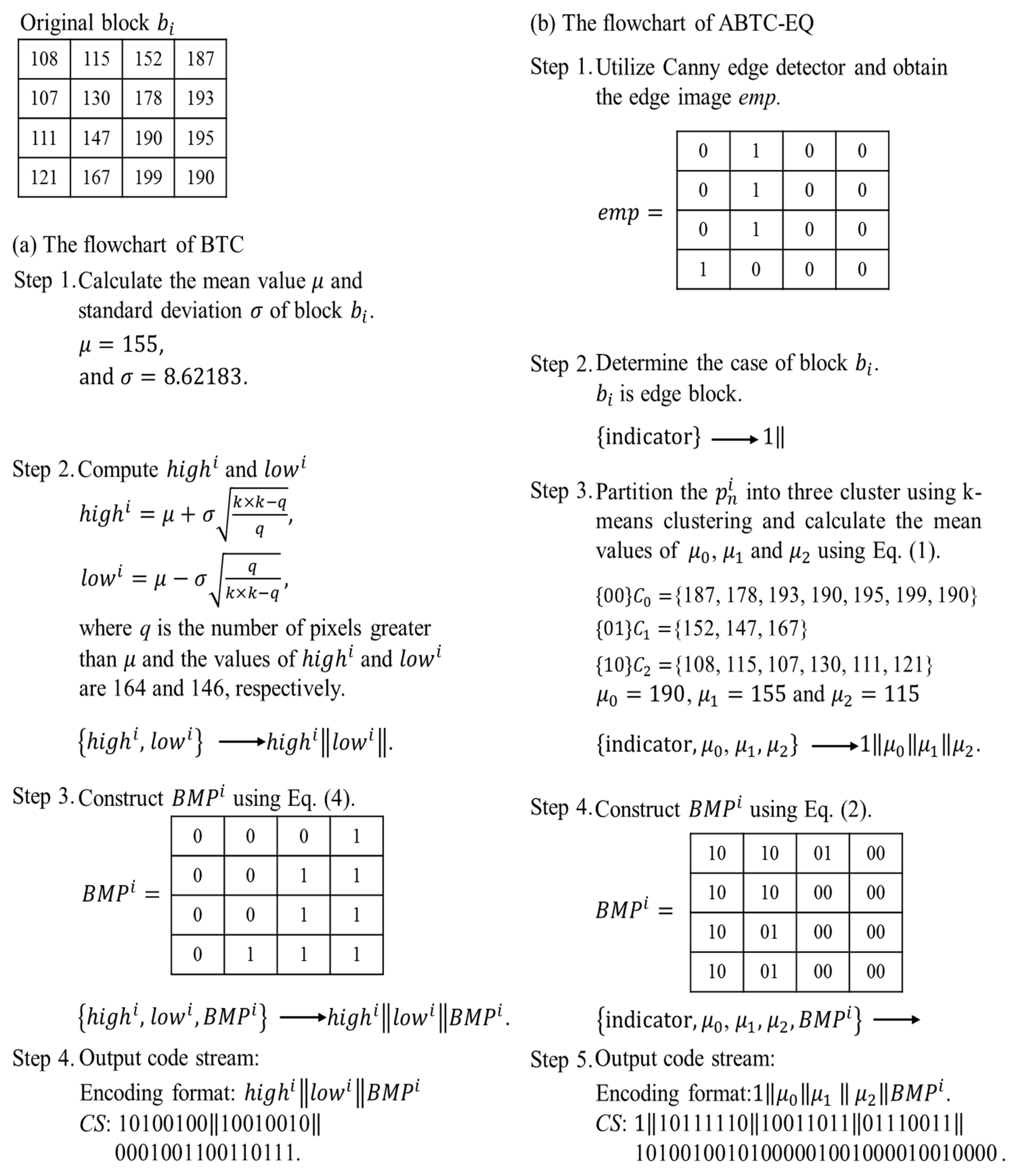
Figure 1a,b show the encoding flowcharts of BTC [13] and ABTC-EQ [23], respectively. To simplify our example shown in Figure 1, a single block sized pixels using BTC and ABTC-EQ, respectively, is demonstrated. We used Equation (9) to calculate the Mean Square Error (MSE) of BTC and ABTC-EQ, whose values were 698 and 55, respectively. Obviously, ABTC-EQ has good performance when a block is in the complexity area.
where and are the values of the decompressed pixel and the original pixel values.
3. Proposed Scheme
This section presents the proposed scheme. In our method, we utilized ABTC-EQ to compress the cover image because its reconstructed image quality is relatively good compared to other BTC variant techniques. Next, ZPF-HS was used to embed the secret information into an ABTC-EQ compressed code stream. To further enlarge the hiding capacity of our proposed method, we also embed the secret data into quantization levels. As background for our proposed scheme, Section 3.1 reviews the zero-point fixed histogram shifting (ZPF-HS) that will be used for data embedding in our approach. Our proposed scheme contains two phases: a data embedding phase and the data extraction and recovery phase, which are demonstrated in Section 3.2 and Section 3.3, respectively.
3.1. Zero-Point Fixed Histogram Shifting (ZPF-HS)
The histogram shifting technique [3], called HS for short, is a simple and efficient hiding method, and has been widely adopted in various reversible data hiding schemes. In this section, the features of HS are explored and then expanded to support a zero-point fixed scenario as zero-point fixed histogram shifting, called ZPF-HS for short. Finally, ZPF-HS is adopted in our proposed scheme.
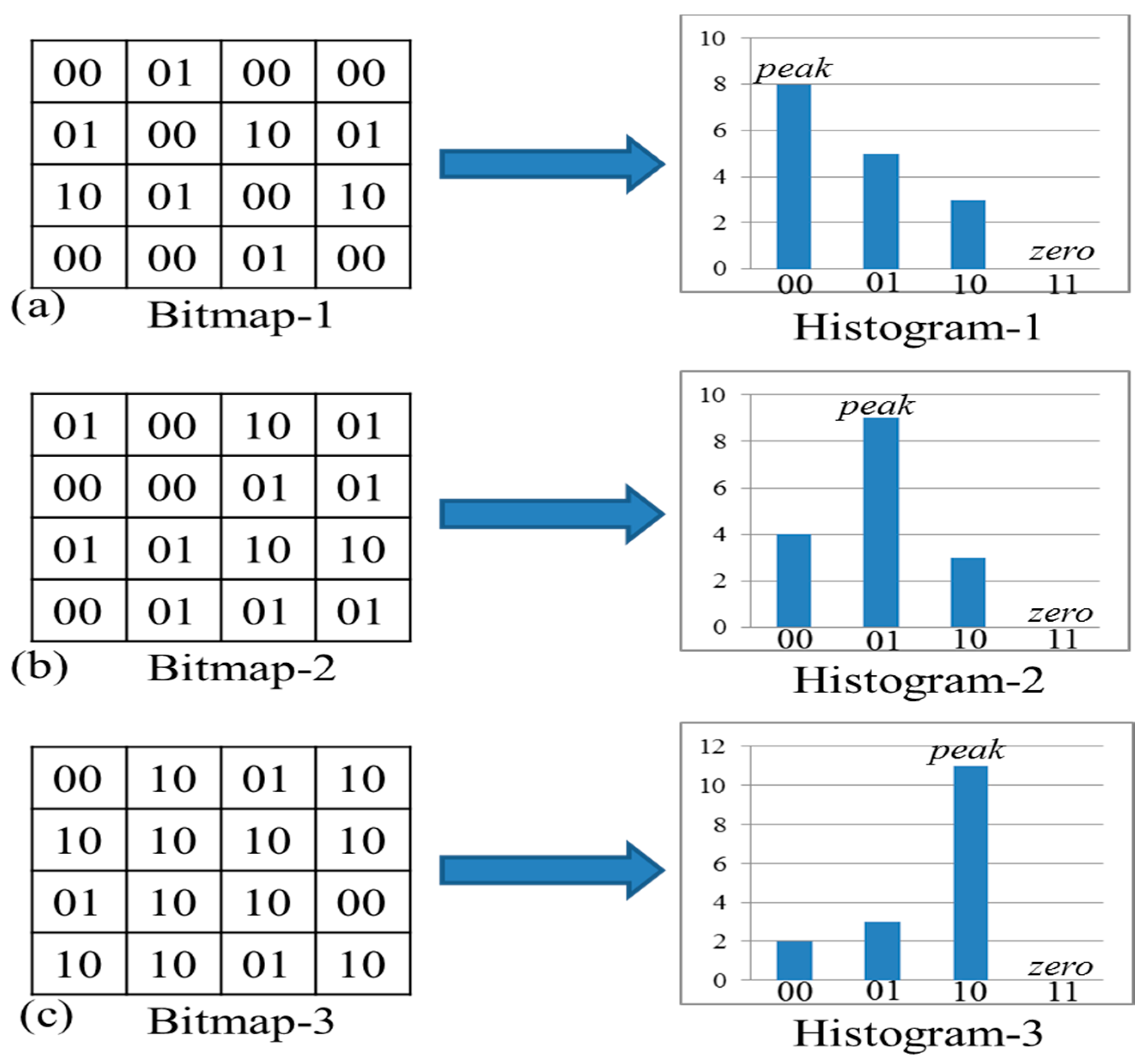
In our proposed method, there are only three histogram bins that need to addressed if the compressed blocks are determined as edge-blocks and the corresponding bit map is the source for our ZPF-HS. Figure 2 shows examples of three possible cases of the bit map for an edge-block. In ABTC-EQ, bits 11 are not being used, as shown in Figure 2. In our scheme, zero point (zero) is always set as 11 and the peak point (peak) is defined as the bit values in the bit map which has a large population.
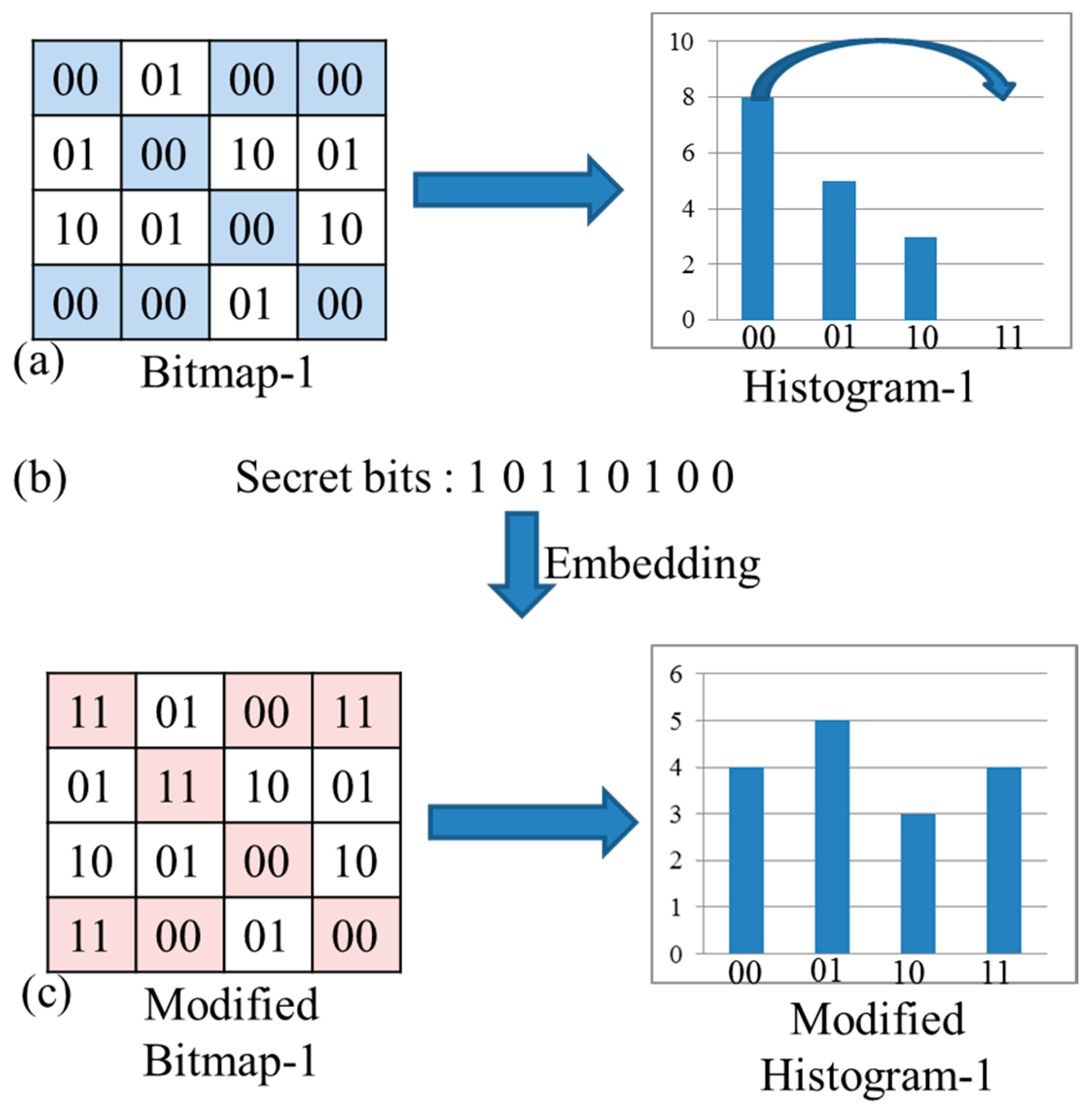
Take Figure 2a for example: there are 8 bit values “00”, 5 bit values “01” and 3 bit values “10” in bit map-1. Therefore, peak point is defined as “00”. We exploit the first case shown in Figure 2a as an example to explain in detail our proposed ZFP-HS in Figure 3. Figure 3a shows the original bit map and its corresponding histogram, Figure 3b presents the secret data and Figure 3c is the result of the modified bit map and its corresponding histogram after embedding. In this example, peak is defined as “00” and zero is defined as “11”, then according to Equation (10) with a zig-zag scan, the secret data can be embedded into the original bit map and the modified bit map is shown in Figure 3c.
3.2. Data Embedding Phase
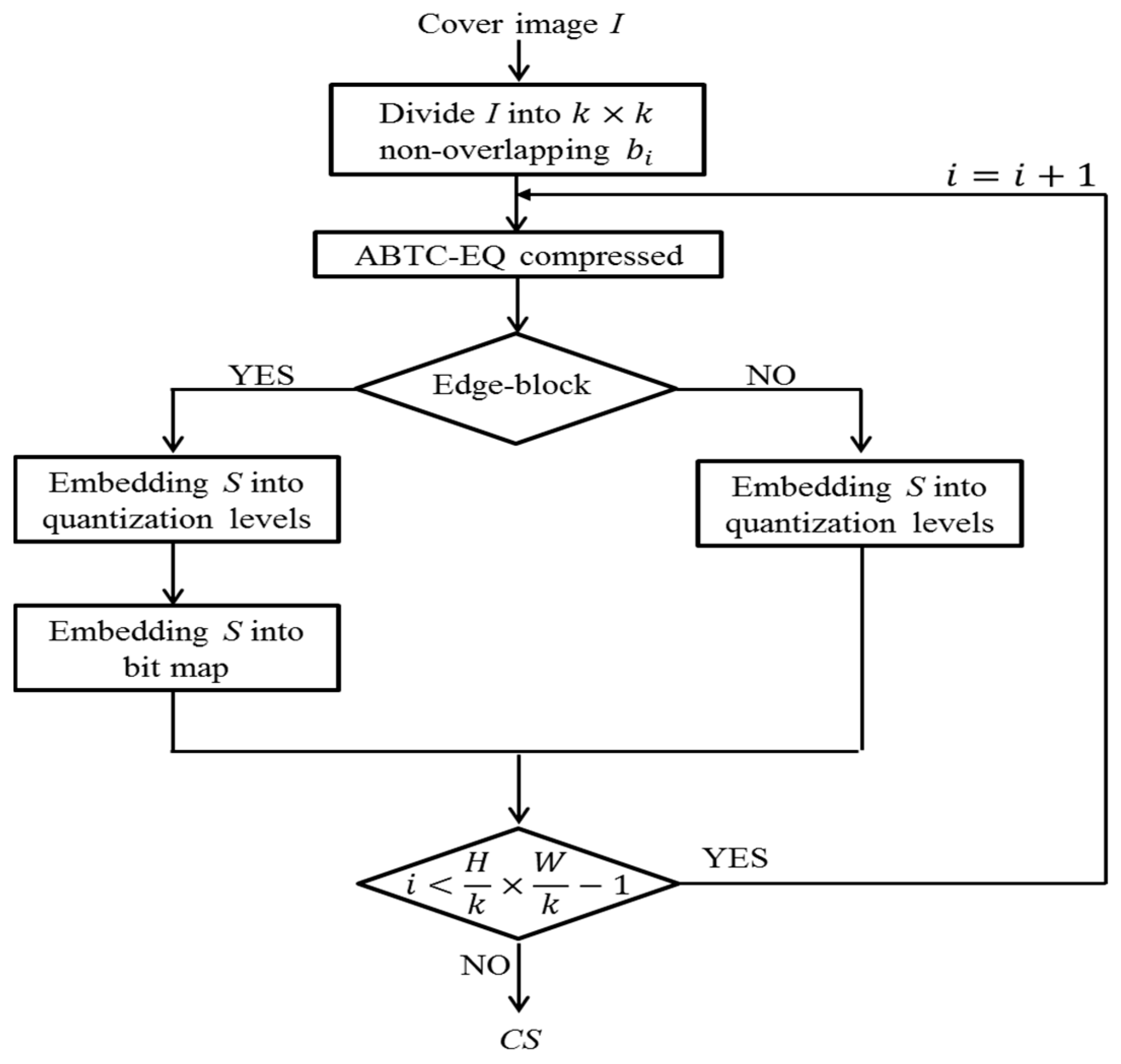
In our proposed data embedding phase, the embedding operations and encoding phase of ABTC-EQ are merged seamlessly. Blocks are identified as non-edge-block and edge-block after Canny edge detection. Therefore, two block types are identified and two cases of data hiding operations need to be explored in our embedding phases as shown in Figure 4. For an edge-block case, both quantization levels and a bit map are used for data hiding. By contrast, only quantization levels are used for data embedding in a non-edge-block.
In our data embedding phase, the input cover image is sized as . Each block is sized pixels, where . Note that the ABTC-EQ procedure is also included as shown in Figure 4. Secret information S is a bitstream in binary form, and is the value of a secret bit in S, where and . N is the number of maximum capacity of cover image I. And S is embedded into the ABTC-EQ compressed code stream of cover image I.
Input: Cover image I and secret information S.
Output: Code stream CS.
Step 1. Divide I into non-overlapping blocks ’s.
Step 2. Utilize ABTC-EQ to compress the current processing block .
Step 3. Determine block to be edge-block or non-edge-block. If block is an edge-block, then go to Step 4. Otherwise, go to Step 8.
Step 4. Insert one bit to serve as the indicator and set it as 1. Then, use Equation (3) to compute the mean values , and of three clusters , and , respectively. Finally, cluster w, which has a large population will be encoded as , where || represents the concatenation operation and .
Step 5. Read the next from S, if , and the remaining clusters will be encoded as , where and . Otherwise, encode by .
Step 6. Embed the next from S into the and obtain a modified by using Equation (10).
Step 7. Output to be part of CS.
Step 8. Insert one bit as the indicator and set it as 0. Then, use Equations (7) and (8) to compute two quantization levels and .
Step 9. Determine the next , if the next = 0, indicator, and will be encoded by . Otherwise, it will be encoded by .
Step 10. Output the indicator, that is the sequence according to the corresponding embedding order of two quantization levels, and the original bit map to be part of CS.
Step 11. Repeat Step 2 to Step 10 until all blocks ’s are processed.
Step 12. Obtain output code stream CS.
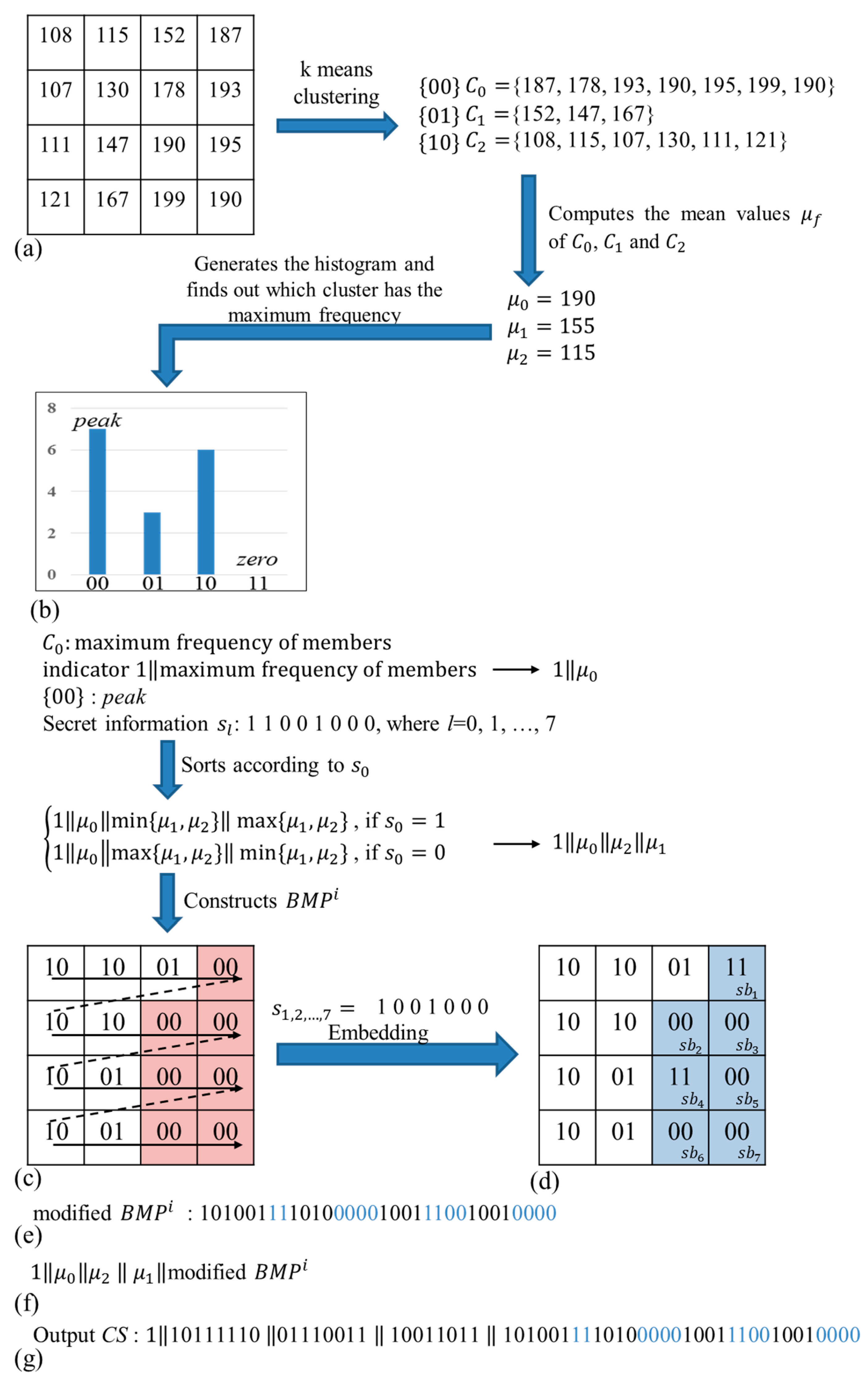
We obtain the modified code stream CS, which concealed the S after all the steps are completed. An example of our proposed data embedding phase is shown in Figure 5 to explain each step in detail. Figure 5a shows an example of a sized block . Figure 5b presents the histogram of three clusters corresponding in block . Figure 5c,d present the original and the modified , respectively. Figure 5e provides the code stream of a modified . Figure 5f is the sequence of the indicator, three quantization levels and modified . Figure 5f presents the binary form of Figure 5g. In Figure 5, all pixels in block will be partitioned into three clusters exploiting k-means clustering. Then, compute the mean values of three clusters using Equation (3). Because has the largest population, the corresponding to is peak. The indicator and three quantization levels ’s will be encoded by while the next is 1. In the next step, construct , embed the next into using Equation (10) and obtain the modified . Finally, we obtain the modified code stream CS.
3.3. Extraction and Recovery Phase
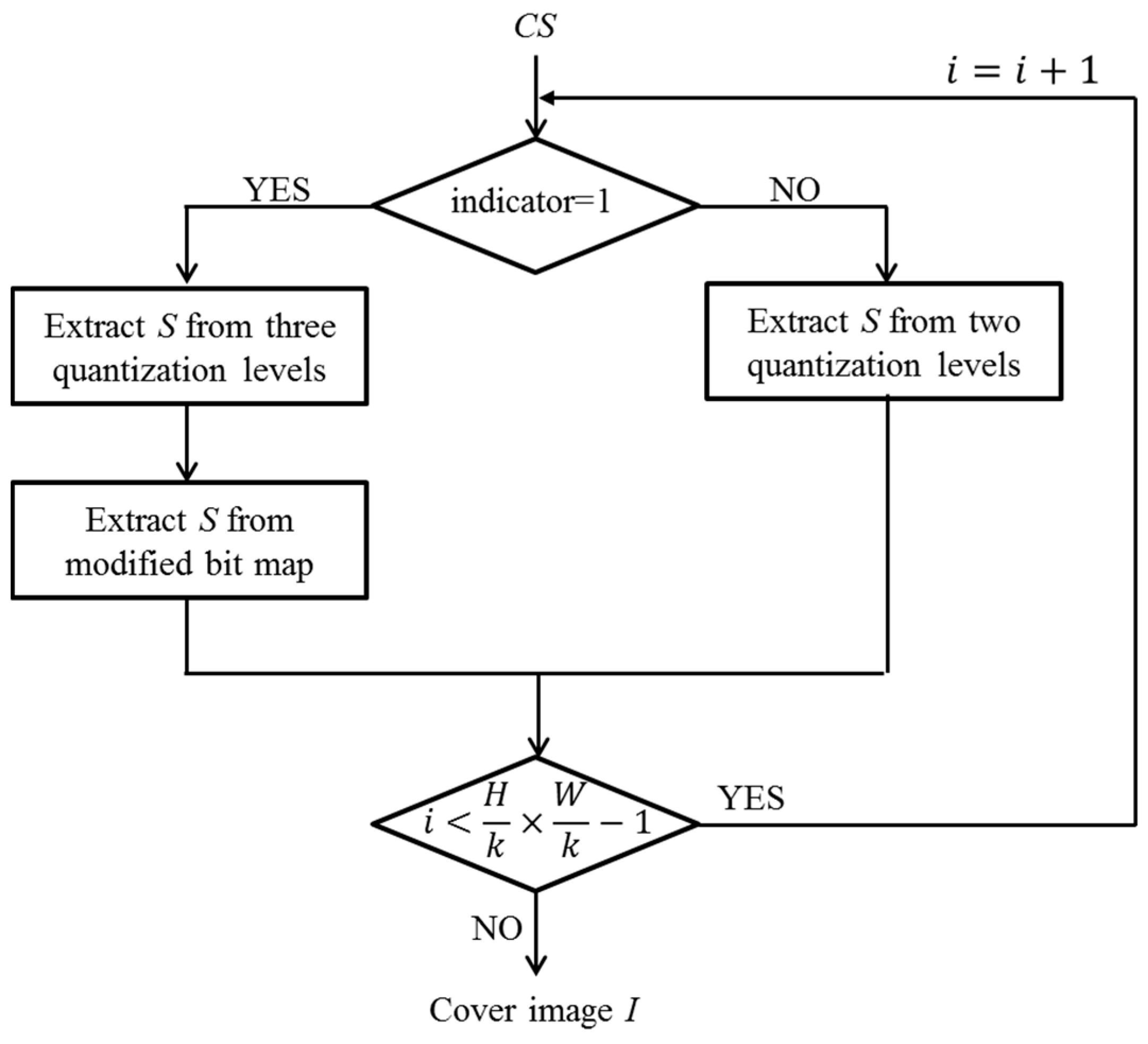
In this section, hidden secret information S is extracted from code stream CS. Because one indicator has been added during our data embedding phase, a decoder can be guided by the indicator to conduct the extraction operation. If the indicator is 1, block will be judged as an edge-block. Three quantization levels will be extracted and among three quantization levels of will serve as the peak. In other words, our proposed scheme does not need extra information to record the value of peak to recover the , as the histogram shifting technique is adopted in our scheme. Flowchart for extraction and recovery phase is shown in Figure 6.
Input: Code stream CS.
Output: Cover image I and secret information S.
Step 1. Read the 1-bit indicator in the CS and determine the value of the indicator, if the indicator value is 1, then go to Step 2. Otherwise, go to Step 8.
Step 2. Read the next 56 bits, then obtain the bit stream of three quantization levels , and , and the modified . Its sequence is .
Step 3. Determine the maximum of and . If , the hidden . Otherwise, the hidden .
Step 4. Construct the and sort , and in descending order. The value of peak is ’s corresponding .
Step 5. Extract the next from the . If , the hidden . And if , the hidden .
Step 6. Modify zero back to peak where .
Step 7. Decompress block according to each ’s corresponding quantization level.
Step 8. Read the next 32 bits, then obtain the bit stream of two quantization levels and , and the original . Its sequence is .
Step 9. Determine the maximum of and . If , the hidden . Otherwise, the hidden .
Step 10. Sort and in descending order and decompress block according to each ’s corresponding quantization level.
Step 11. Repeat Steps 1 to 10 until all bits in CS are read and proceeded.
Step 12. Obtain secret information S and decompressed cover image I.
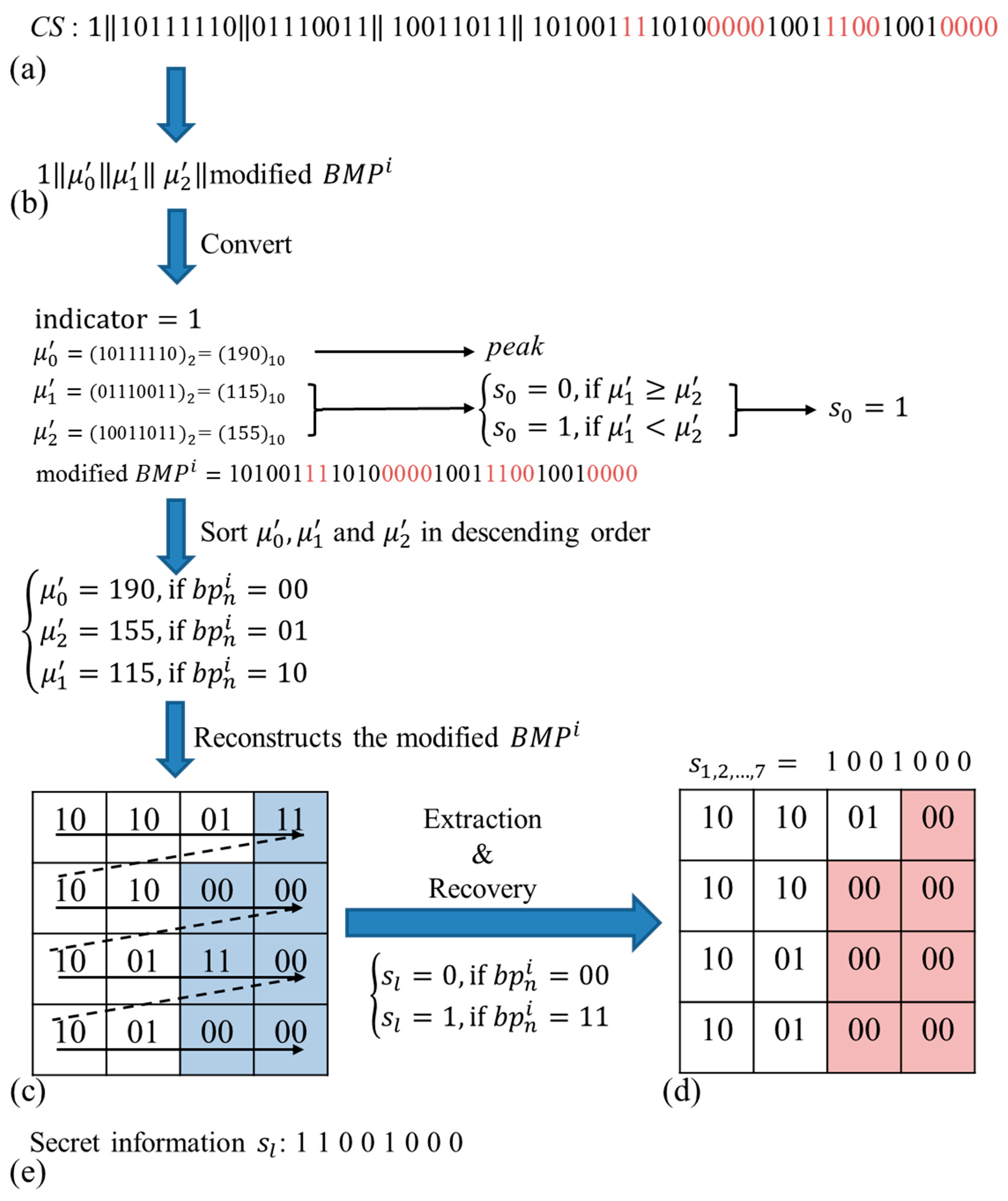
After all steps are completed, decompressed cover image I and secret information S are obtained. We also provide an example to further clarify the extraction and recovery phases, which is shown in Figure 7. Figure 7a shows the CS in binary form, Figure 7b presents the sequence of indicator, three quantization levels and modified , Figure 7c shows the modified , Figure 7d presents the original and Figure 7e provides the extracted S. In Step 1, three quantization levels , and are converted into decimal values. Because , hidden . In Step 2, , and are sorted in descending order, and corresponding to is peak, so the of peak is determined as 00. As the next step, the modified is constructed and are extracted from a modified . If , the hidden . If , the hidden . After extracting all S from the modified , change all values of 11 into peak. Finally, we can obtain the original as shown in Figure 7d.
4. Experimental Results
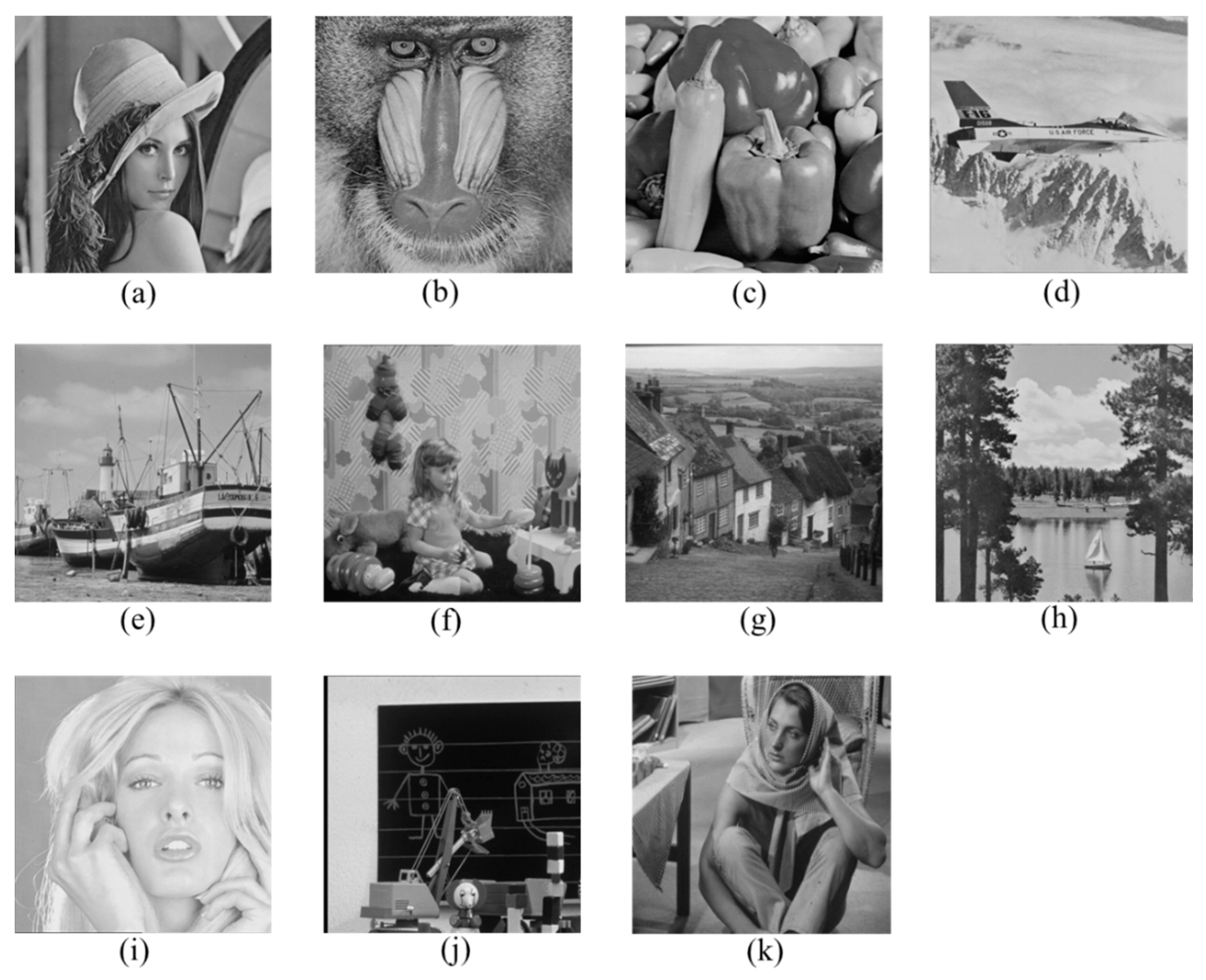
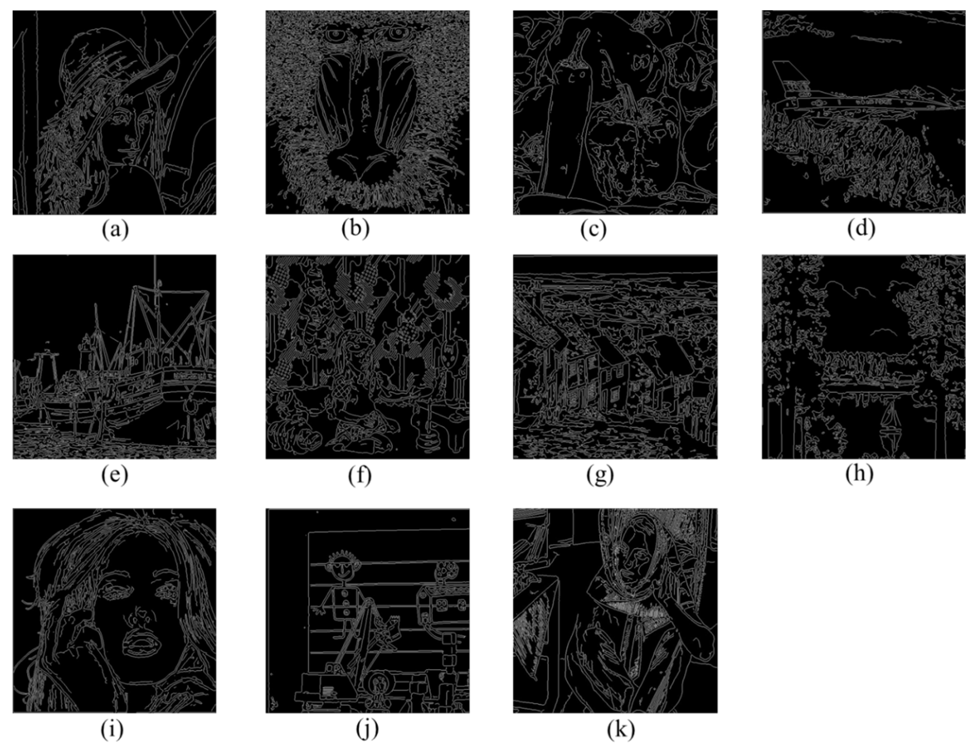
We describe some experimental results in this section to demonstrate hiding capacity, output code stream size and the compression ratio in our proposed method. The eleven test grayscale cover images as shown in Figure 8 were used for our experiments. The results of their edge images based on Canny edge detection are shown in Figure 9.
To illustrate the performance of our proposed method, the results of our scheme with two different block sizes, pixels and , are shown in Table 1 and Table 2, respectively. In Table 1 and Table 2, we present embedding capacity (number of bits), the size of CS (number of bits), compressed ratio (CR) (%) and peak signal-to-noise-ratio (PSNR) (dB) of ABTC-EQ and BTC in two different block sizes, pixels and , respectively. Obviously, compressing the image to exploit ABTC-EQ can obtain an overall better image quality than BTC, as seen in Table 1 and Table 2 by exploiting Equation (12). Because our scheme embeds the secret data into the compression code stream, a decompressed image cannot be directly obtained from the CS that carries the hidden secret data. As for PSNR (db), it denotes the decompressed image of the recovery CS. The CR of conventional BTC is 0.25 using Equation (11). The size of output CS (number of bits) and PSNR (dB) using ABTC-EQ in the case of an block size for is similar to the result of the BTC of the block size for . In our scheme, we utilize the characteristic of ABTC-EQ to apply our proposed ZPF-HS to embed the secret data, and we see that the size of CS before and after hiding are the same in our method. Despite the size, our CS (number of bits) is very large because of the cost of bits, while is the edge-block. But the problem of a blocking effect can be better solved with our method than with other compression methods. The average hiding capacity (number of bits) and PSNR (dB) in our experiment are 74,138 (number of bits) and 36.327 (number of bits), respectively. Additionally, the PSNR (dB) means the resulting image after extracting the secret information in Table 1 and Table 2.
From Table 1, we can see that the average capacity is around 74,000 bits and the CR is about 0.3358% when the block size is pixels.
In comparison, we can see that the average capacity is up to 90,000 bits and the CR is about 0.2409% when the block size is pixels as shown in Table 2. Certainly, the average image quality will be slightly decreased to 33.368 dB, but it is significantly higher than the average PSNR offered by conventional BTC.
To demonstrate the performance results for our proposed scheme, the proposed method in this experiment was compared to previous schemes, i.e., Chang et al. [14], Li et al. [15], Sun et al. [16] and Lin et al. [19] in terms of embedding capacity (number of bits) and embedding efficiency (EF) (%), the results of which are shown in Table 3. These four existing schemes are selected and compared with our proposed scheme because they are reversible data hiding schemes and they are either designed for BTC or AMBTC. Moreover, their hiding strategies are embedding secrets into bitmap and two quantization levels, which are the same as ours. Here, EF was used to evaluate embedding efficiency, which is defined as follows:
where is the size of the output CS and Capacity is the embedding capacity of each test image.
In this experiment, the size of all test images were pixels and the block size was set as . In this experiment, our embedding capacity was better than three previous schemes [14,16,17]. While Lin et al.’s scheme provides good hiding capacity performance, their scheme extracts the secret data from the resulting images instead of extracting the secret information from the output CS (number of bits). Therefore, the size of each CS (number of bits) in Lin et al.’s scheme is . The size of our CS (number of bits) remains unchanged even after embedding the secret information. In our scheme, the sizes of CS’s for, “Lena,” “F-16,” “Sailboat,” “Girl,” “Toys” and “Barbara” are 480,096 (number of bits); 474,264 (number of bits); 495,432 (number of bits); 544,104 (number of bits); 455,112 (number of bits) and 510,048 (number of bits), respectively, and are shown in Table 3. For the purpose of having a better comparison with the previous four methods, we utilize EF (%) to analyze the performance of our scheme and compare to other schemes using Equation (13). Our proposed scheme obtained a higher EF than the previous four methods. Moreover, the EF offered by Lin et al.’s scheme is lower than ours because their results are presented as images rather than from the code stream.
5. Conclusions
This paper presented a novel reversible data hiding method using block truncation coding based on an edge-based quantization approach. By applying two embedding levels and our proposed ZPF-HS to hide the secret information, it was possible to have a high capacity, high PSNR and high EF despite the generation of a large CS size. In addition, we utilized n bits after the indicator to record the peak while blocks are edge-block to ensure that our method exactly restores the original cover image. The experimental results show that our proposed method is indeed suitable for hiding large volumes of information in multimedia. However, it still remains that one value 11 of cannot be used in the ABTC-EQ compressed method. Our future work will concentrate on how to utilize this value that is not being used in ABTC-EQ to enhance image quality and how to exploit this feature to embed more secret information into compressed code. Moreover, two possible approaches, i.e., CNN and hyperchaos, will be explored and applied when we try to study the above two objectives.
Author Contributions
Conceptualization and funding acquisition, C.-C.L.; software and writing-original draft preparation, Z.-M.W.; validation, C.-C.C.
Funding
This research was funded by Ministry of Science and Technology grant number 105-2410-H-126-005-MY3.
Conflicts of Interest
The authors declare no conflict of interest.
References
- Chan, C.K.; Cheng, L.M. Hiding data in images by simple LSB sub-stitution. Pattern Recognit. 2004, 37, 469–474. [Google Scholar] [CrossRef]
- Zhang, X.P.; Wang, S.Z. Efficient steganographic embedding by exploiting modification direction. IEEE Commun. Lett. 2006, 10, 781–783. [Google Scholar] [CrossRef]
- Ni, Z.; Shi, Y.Q.; Ansari, N.; Su, W. Reversible data hiding. IEEE Trans. Circuits Syst. Video Technol. 2006, 16, 354–362. [Google Scholar]
- Tai, W.L.; Yeh, C.M.; Chang, C.C. Reversible data hiding based on histogram modification of pixel differences. IEEE Trans. Circuits Syst. Video Technol. 2009, 19, 906–910. [Google Scholar]
- Zhang, D.X.; Pan, Z.E.; Li, H.H. A contour-based semi-fragile image watermarking algorithm in DWT domain. In Proceedings of the 2nd International Workshop on Education Technology and Computer Science (ETCS), Wuhan, China, 6–7 March 2010; Volume 3, pp. 228–231. [Google Scholar]
- Wu, X.; Sun, W. Robust copyright protection scheme for digital images using overlapping DCT and SVD. Appl. Soft Comput. 2013, 13, 1170–1182. [Google Scholar] [CrossRef]
- Chan, Y.K.; Chen, W.T.; Yu, S.S.; Ho, Y.A.; Tsai, C.S.; Chu, Y.P. A HDWT-based reversible data hiding method. J. Syst. Softw. 2009, 82, 411–421. [Google Scholar] [CrossRef]
- Thabit, R.; Khoo, B.E. Robust reversible watermarking scheme using slantlet transform matrix. J. Syst. Softw. 2014, 88, 74–86. [Google Scholar] [CrossRef]
- Zhang, X.P.; Wang, S.Z.; Qian, Z.X.; Feng, G. Reversible fragile watermarking for locating tampered blocks in JPEG images. Signal Process. 2010, 90, 3026–3036. [Google Scholar] [CrossRef]
- Wang, K.; Lu, Z.M.; Hu, Y.J. A high capacity lossless data hiding scheme for JPEG images. J. Syst. Softw. 2013, 86, 1965–1975. [Google Scholar] [CrossRef]
- Chang, C.C.; Kieu, T.D.; Wu, W.C. A lossless data embedding technique by joint neighboring coding. Pattern Recognit. 2009, 42, 1597–1603. [Google Scholar] [CrossRef]
- Lee, J.D.; Chiou, Y.H.; Guo, J.M. Reversible data hiding based on histogram modification of SMVQ indices. IEEE Trans. Inf. Forensics Secur. 2010, 5, 638–648. [Google Scholar] [CrossRef]
- Chang, C.C.; Lin, C.Y.; Fan, F.H. Lossless data hiding for color images based on block truncation coding. Pattern Recognit. Lett. 2008, 41, 2347–2357. [Google Scholar] [CrossRef]
- Chang, C.C.; Lin, C.Y.; Fan, Y.H. Reversible steganography for BTC-compressed images. Fundam. Inform. 2011, 109, 121–134. [Google Scholar]
- Li, C.H.; Lu, Z.M.; Su, Y.X. Reversible data hiding for BTC-compressed images based on bitmplane flipping and histogram shifting of mean tables. Inf. Technol. J. 2011, 10, 1421–1426. [Google Scholar]
- Sun, W.; Lu, Z.M.; Wen, Y.C. High performance reversible data hiding for block truncation coding compressed images. Signal Image Video Process. 2013, 7, 297–306. [Google Scholar] [CrossRef]
- Lo, C.C.; Hu, Y.C.; Chen, W.L.; Wu, C.M. Reversible data hiding scheme for BTC-compressed images based on histogram shifting. Int. J. Secur. Appl. 2014, 8, 301–314. [Google Scholar] [CrossRef]
- Chang, I.C.; Hu, Y.C.; Chen, W.L.; Lo, C.C. High capacity reversible data hiding scheme based on residual histogram shifting for block truncation coding. Signal Process. 2015, 108, 376–388. [Google Scholar] [CrossRef]
- Lin, C.C.; Liu, X.L.; Tai, W.L.; Yuan, S.M. A novel reversible data hiding scheme based on AMBTC compression technique. Multimed. Tools Appl. 2015, 74, 3823–3842. [Google Scholar] [CrossRef]
- Delp, E.J.; Mitchell, O.R. Image compression using block truncation coding. IEEE Trans. Commun. 1979, 27, 1335–1342. [Google Scholar] [CrossRef]
- Canny, J. A computational approach to edge detection. IEEE Trans. Pattern Anal. Mach. Intell. 1986, 8, 679–698. [Google Scholar] [CrossRef]
- Kanungo, T.; Mount, D.M.; Netanyahu, N.S.; Piatko, C.D.; Silverman, R.; Wu, A.Y. An efficient k-means clustering algorithm: Analysis and implementation. IEEE Trans. Pattern Anal. Mach. Intell. 2002, 24, 881–892. [Google Scholar] [CrossRef]
- Gray, R.M. Vector quantization. IEEE Assp Mag. 1984, 1, 4–29. [Google Scholar] [CrossRef]
- Kim, T. Side match and overlap match vector quantizers for images. IEEE Trans. Image Process. 1992, 1, 170–185. [Google Scholar] [CrossRef] [PubMed]
- Mathews, J.; Nair, M.S. Adaptive block truncation coding technique using edge-based quantization approach. Comput. Electr. Eng. 2015, 43, 169–179. [Google Scholar] [CrossRef]
- Goljan, M.; Fridrich, J.; Du, R. Distortion-free data embedding for images. In Proceedings of the 4th International Workshop on Information Hiding, London, UK, 25–27 April 2001; pp. 27–41. [Google Scholar]
- Barton, J.M. Method and Apparatus for Embedding Authentication Information within Digital Data. U.S. Patent US5646997A, 8 July 1997. [Google Scholar]
- Celik, M.U.; Sharma, G.; Tekalp, A.M.; Saber, E. Reversible data hiding. In Proceedings of the IEEE International Conference on Image Processing, Rochester, NY, USA, 22–25 September 2002; Volume 2, pp. 157–160. [Google Scholar]
- Wu, X. Lossless compression of continuous-tone images via context selection, quantization, and modeling. IEEE Trans. Image Process. 1997, 6, 656–664. [Google Scholar] [PubMed]
- Tian, J. Reversible data embedding using a difference expansion. IEEE Trans. Circuits Syst. Video Technol. 2003, 13, 890–896. [Google Scholar] [CrossRef] [Green Version]
- Alattar, A.M. Reversible watermark using the difference expansion of a generalized integer transform. IEEE Trans. Image Process. 2004, 13, 1147–1156. [Google Scholar] [CrossRef] [PubMed]
- Li, X.L.; Yang, B.; Zeng, T.Y. Efficient reversible watermarking based on adaptive prediction-error expansion and pixel selection. IEEE Trans. Image Process. 2011, 20, 3524–3533. [Google Scholar]
- Chang, C.C.; Huang, Y.H.; Tsai, H.Y.; Qin, C. Prediction-based reversible data hiding using the difference of neighboring pixels. Int. J. Electron. Commun. 2012, 66, 758–766. [Google Scholar] [CrossRef]
Figure 1.
Compression flowcharts of block truncation coding (BTC) and adaptive block truncation coding based on edge-based quantization (ABTC-EQ algorithms): (a) BTC encoding and (b) ABTC-EQ encoding.
Figure 1.
Compression flowcharts of block truncation coding (BTC) and adaptive block truncation coding based on edge-based quantization (ABTC-EQ algorithms): (a) BTC encoding and (b) ABTC-EQ encoding.

Figure 2.
(a–c) are the bit maps and histograms of each case.

Figure 3.
Example of operations in our ZPF-HS. (a) Original bit map and histogram, (b) secret bits and (c) modified bit map and histogram.
Figure 3.
Example of operations in our ZPF-HS. (a) Original bit map and histogram, (b) secret bits and (c) modified bit map and histogram.

Figure 4.
The flowchart of data embedding phase.

Figure 5.
(a) Block , (b) histogram of block , (c) original , (d) modified , (e) the code stream of modified , (f) structure of code stream CS and (g) output code stream CS.
Figure 5.
(a) Block , (b) histogram of block , (c) original , (d) modified , (e) the code stream of modified , (f) structure of code stream CS and (g) output code stream CS.

Figure 6.
Flowchart for extraction and recovery phase.

Figure 7.
(a) Code stream CS, (b) example of output format, (c) modified , (d) recovery and (e) secret information S.
Figure 7.
(a) Code stream CS, (b) example of output format, (c) modified , (d) recovery and (e) secret information S.

Figure 8.
Test images: (a) Lena, (b) Baboon, (c) Peppers, (d) F-16, (e) Fishing Boat, (f) Girl, (g) Gold hill, (h) Sailboat, (i) Tiffany, (j) Toys and (k) Barbara.
Figure 8.
Test images: (a) Lena, (b) Baboon, (c) Peppers, (d) F-16, (e) Fishing Boat, (f) Girl, (g) Gold hill, (h) Sailboat, (i) Tiffany, (j) Toys and (k) Barbara.

Figure 9.
Canny edge detection images of test images: (a) Lena, (b) Baboon, (c) Peppers, (d) F-16, (e) Fishing Boat, (f) Girl, (g) Gold hill, (h) Sailboat, (i) Tiffany, (j) Toys, and (k) Barbara.
Figure 9.
Canny edge detection images of test images: (a) Lena, (b) Baboon, (c) Peppers, (d) F-16, (e) Fishing Boat, (f) Girl, (g) Gold hill, (h) Sailboat, (i) Tiffany, (j) Toys, and (k) Barbara.


Table 1.
Performance of our proposed method in block sizes for each block .
| Capacity (Number of Bits) | CS (Number of Bits) | CR (%) | ABTC-EQ PSNR (dB) | BTC PSNR (dB) | |
|---|---|---|---|---|---|
| Lena | 63,342 | 675,384 | 0.3220 | 37.115 | 33.659 |
| Baboon | 102,999 | 796,152 | 0.3796 | 31.255 | 27.752 |
| Peppers | 63,603 | 670,944 | 0.3199 | 37.486 | 34.151 |
| F-16 | 66,094 | 675,240 | 0.3220 | 37.405 | 33.359 |
| Fishing boat | 70,813 | 695,712 | 0.3317 | 35.944 | 32.000 |
| Girl | 88,051 | 739,800 | 0.3528 | 38.157 | 34.706 |
| Gold hill | 89,745 | 751,176 | 0.3582 | 37.075 | 33.659 |
| Sailboat | 69,283 | 689,736 | 0.3289 | 34.653 | 31.139 |
| Tiffany | 72,395 | 691,536 | 0.3298 | 40.153 | 36.991 |
| Toys | 56,115 | 650,696 | 0.3103 | 37.666 | 33.216 |
| Barbara | 73,083 | 710,496 | 0.3388 | 32.688 | 29.868 |
| Average | 74,138 | 704,261 | 0.3358 | 36.327 | 32.773 |
Table 2.
Performance of our proposed method in block sizes for each block .
| Capacity (Number of Bits) | CS (Number of Bits) | CR (%) | ABTC-EQ PSNR (dB) | BTC PSNR (dB) | |
|---|---|---|---|---|---|
| Lena | 76,671 | 480,096 | 0.2289 | 33.892 | 30.273 |
| Baboon | 110,340 | 565,488 | 0.2696 | 29.025 | 25.843 |
| Peppers | 83,774 | 486,792 | 0.2321 | 33.995 | 30.273 |
| F-16 | 80,009 | 474,264 | 0.2261 | 34.276 | 30.204 |
| Fishing boat | 84,791 | 489,960 | 0.2336 | 32.821 | 29.042 |
| Girl | 108,217 | 544,104 | 0.2594 | 34.934 | 31.055 |
| Gold hill | 114,533 | 559,440 | 0.2668 | 33.859 | 30.723 |
| Sailboat | 87,997 | 495,432 | 0.2362 | 31.887 | 28.129 |
| Tiffany | 90,900 | 497,088 | 0.2370 | 37.239 | 33.979 |
| Toys | 70,889 | 455,112 | 0.2170 | 34.198 | 30.069 |
| Barbara | 87,264 | 510,048 | 0.2432 | 30.917 | 27.832 |
| Average | 90,489 | 505,257 | 0.2409 | 33.368 | 29.766 |
Table 3.
Embedding capacity (number of bits) and EF (%) for the proposed scheme and four previous schemes.
Table 3.
Embedding capacity (number of bits) and EF (%) for the proposed scheme and four previous schemes.
| Schemes | Parameters | Lena | F-16 | Sailboat | Girl | Toys | Barbara |
|---|---|---|---|---|---|---|---|
| Chang et al. [14] | Capacity | 31,011 | 30,518 | 28,766 | 30,962 | 27,870 | 30,151 |
| CS | 524,288 | 524,288 | 524,288 | 524,288 | 524,288 | 524,288 | |
| EF | 0.0591 | 0.0582 | 0.0549 | 0.0591 | 0.0532 | 0.0575 | |
| Li et al. [15] | Capacity | 16,789 | 17,659 | 17,082 | 16,990 | 17,761 | 16,755 |
| CS | 524,288 | 524,288 | 524,288 | 524,288 | 524,288 | 524,288 | |
| EF | 0.032 | 0.0337 | 0.0326 | 0.0324 | 0.0339 | 0.032 | |
| Sun et al. [16] | Capacity | 64,008 | 64,008 | 64,008 | 64,008 | 64,008 | 64,008 |
| CS | 524,288 | 524,288 | 524,288 | 524,288 | 524,288 | 524,288 | |
| EF | 0.1221 | 0.1221 | 0.1221 | 0.1221 | 0.1221 | 0.1221 | |
| Lin et al. [19] | Capacity | 262,112 | 261,984 | 262,096 | 262,128 | 262,112 | 262,128 |
| CS | 2,097,152 | 2,097,152 | 2,097,152 | 2,097,152 | 2,097,152 | 2,097,152 | |
| EF | 0.125 | 0.1249 | 0.125 | 0.125 | 0.125 | 0.125 | |
| Our scheme | Capacity | 76,671 | 80,009 | 84,791 | 108,217 | 70,889 | 87,264 |
| CS | 480,096 | 474,264 | 495,432 | 544,104 | 455,112 | 510,048 | |
| EF | 0.1597 | 0.1687 | 0.1731 | 0.1989 | 0.1558 | 0.1711 |
© 2019 by the authors. Licensee MDPI, Basel, Switzerland. This article is an open access article distributed under the terms and conditions of the Creative Commons Attribution (CC BY) license (http://creativecommons.org/licenses/by/4.0/).
Share and Cite
MDPI and ACS Style
Lin, C.-C.; Chang, C.-C.; Wang, Z.-M. Reversible Data Hiding Scheme Using Adaptive Block Truncation Coding Based on an Edge-Based Quantization Approach. Symmetry 2019, 11, 765. https://0-doi-org.brum.beds.ac.uk/10.3390/sym11060765
AMA Style
Lin C-C, Chang C-C, Wang Z-M. Reversible Data Hiding Scheme Using Adaptive Block Truncation Coding Based on an Edge-Based Quantization Approach. Symmetry. 2019; 11(6):765. https://0-doi-org.brum.beds.ac.uk/10.3390/sym11060765
Chicago/Turabian StyleLin, Chia-Chen, Ching-Chun Chang, and Zhi-Ming Wang. 2019. "Reversible Data Hiding Scheme Using Adaptive Block Truncation Coding Based on an Edge-Based Quantization Approach" Symmetry 11, no. 6: 765. https://0-doi-org.brum.beds.ac.uk/10.3390/sym11060765
Note that from the first issue of 2016, this journal uses article numbers instead of page numbers. See further details here.