
Study of Cascading Failure in Multisubnet Composite Complex Networks


1
School of Data Science and Software Engineering, Qingdao University, Qingdao 266071, China
2
Department of Automatic Control Engineering, Feng Chia University, Taichung 40724, Taiwan
3
Department of Aeronautical Engineering, Chaoyang University of Technology, Taichung 413, Taiwan
*
Authors to whom correspondence should be addressed.
Symmetry 2021, 13(3), 523; https://0-doi-org.brum.beds.ac.uk/10.3390/sym13030523
Submission received: 17 February 2021
/
Revised: 11 March 2021
/
Accepted: 19 March 2021
/
Published: 23 March 2021
(This article belongs to the Special Issue Selected Papers from IIKII 2020 Conferences II)
Abstract
:Current research on the cascading failure of coupling networks is mostly based on hierarchical network models and is limited to a single relationship. In reality, many relationships exist in a network system, and these relationships collectively affect the process and scale of the network cascading failure. In this paper, a composite network is constructed based on the multisubnet composite complex network model, and its cascading failure is proposed combined with multiple relationships. The effect of intranetwork relationships and coupling relationships on network robustness under different influencing factors is studied. It is shown that cascading failure in composite networks is different from coupling networks, and increasing the strength of the coupling relationship can significantly improve the robustness of the network.
1. Introduction
With the development of information technology and society, a real-life network system is a coupling network composed of two or more sub-networks. In a coupling network, systems are interconnected and work together to improve the operational efficiency of the entire network, which is highly convenient for human production and life. Due to the complexity of the network structure and function, cascading failure can easily occur under the action of various factors. In recent years, the consequences of such incidents are immeasurable [1,2,3], and the study of cascading failure is important to prevent the occurrence of large-scale network failures.
The study of cascading failure in complex networks has important theoretical and practical significance for improving the robustness and invulnerability of networks. Albert et al. firstly studied cascading failures in scale-free networks and random networks, and compared the effects of random attack and deliberate attack on cascading failures. As cascading failures are common in power, communication, transportation, Internet and various infrastructure networks, experts in various fields have conducted extensive and in-depth research on cascading failures in complex networks from different perspectives, and proposed different cascading failure models.
The first study on cascading failure was carried out for a single complex network. The main models include OPA (ORNL-PSerc-Alaska) model [4], CASCADE model [5], sand pile model [6], load-capacity model [7]; Kinney et al. [8] used the OPA model to analyze the cascading failure of the North American power network. The research results show that after the failure node transfers the load to its neighbor node, more network nodes will fail, resulting in the “collapse” of the whole power network. Wang et al. [9] proposed a cascading failure model based on random walk betweenness by setting the initial capacity of nodes according to the betweenness of nodes in the network. Tian et al. [10] think that the node betweenness cannot fully reflect the initial load on the edge in traffic road network, so a capacity-load model based on the weight of edge betweenness and edge is proposed to define the initial load, and the cascading failure problem in the urban traffic road network is studied by using this model. Motter et al. [11] proposed the Motter–Lai (ML) model, which is a typical capacity-load model. They assume that the information in the network is transmitted along the shortest path between nodes, the initial load of the node is determined by the betweenness of the node, and the capacity of the node is directly proportional to the initial load growth rate of the node. Crukitti et al. [12] proposed an improved ML model. In the improved ML model, when a node in the network fails due to the load exceeding the capacity, the node does not need to be removed from the network, and only needs to reduce the information transmission efficiency from other nodes to the node.
The study of cascading failure in coupling networks started in 2010 with the work of Buldyrev [13], who used the example of two-layer coupling networks and found that in coupling networks, by randomly attacking nodes in a network, the cascading failure phenomenon in the coupling network is different from that in a single network; a theoretical framework was developed for this phenomenon. Subsequently, the cascading failure of coupling networks has been extensively studied based on this framework, and many conclusions have been drawn that are different from those of a single network.
Current research on cascading failure in coupling networks can be divided into three main categories: networks based on the one-to-one coupling of nodes on both sides [13,14,15,16,17,18,19,20,21], and one-to-many and many-to-many coupling networks [22,23,24,25,26]. Regarding one-to-one coupled networks, it was found in the literature [15] that cascading failure is more likely to occur when attacking the coupled nodes in a coupling network; Gao et al. [16], in their study of coupling networks under different attack methods, found that cascading failure is more likely to occur when attacking the coupled nodes in a coupling network. Dong et al. [20] studied the robustness of coupling networks under varying coupling relationships and found that the greater the probability of coupling nodes with similar degrees between networks, the stronger the robustness of the network. Shao et al. [21] used the partially coupled and one-to-one to fully couple coupling network models, and proposed the edge addition strategy in low relative betweenness and edge coupling addition strategy in low relative betweenness.
For the network of one-to-many and many-to-many coupling of nodes on both sides, Cheng et al. [22] proposed a coupling network model with multiple support dependencies and found it to be more robust than one-to-one interdependent networks; Fu et al. [23] studied the effects of directionality, redundancy, and the degree of dependency on robustness in coupled networks, and found that the robustness of networks based on directed dependencies is lower than that of networks based on undirected dependencies. Min et al. [24] analyzed the influence of the dependency ratio and dependency redundancy on the robustness of a coupling network, and proposed a global homogeneous interdependency network coupling model. Shin et al. [25] proposed a cascading failure model in which the coupled and internal edges are associated with the initial load, and found that the robustness of the network is strongest when the ratio of the external and internal degrees to the load reaches a certain value.
The above studies on cascading failure of a coupling network are based on the hierarchical network model and are limited to a single relationship, but in reality, there are many relationships in a network system. In this paper, we propose a cascading failure model for composite networks based on the multisubnet composite complex network model, and mainly study the effects of intranetwork relationships and coupling relationships on composite networks under different influencing factors.
2. Materials and Methods
2.1. Composite Network Model
According to the multisubnet composite complex network model [26], the two initially constructed vector complex networks are denoted by and , respectively, where , , and denote the composite networks A and B. , is the intranetwork relation, the coupling relation, and the vector complex network A as the base. Under the load mapping , the composite network will be loaded to , where the loading relation represents the coupling relation, and the total number of nodes of the composite networks A and B is set to and , respectively. The new vector composite network constructed according to the above conditions is set to , where , the total number of nodes of the composite network is , as shown in Figure 1.
The newly constructed composite network in Figure 1 has two subnets, A and B. The coupling relationship is set such that subnet B depends on A, and the direction of dependence is unidirectional. The degrees of , are set to ,. The degrees of relations , regarding nodes in subnet B are set to , respectively. In addition, each relationship has a relationship strength, which represents the relationship strength of the effect on nodes and edges. The inter-relationship strength scale parameter is set to .
2.2. Coupling Network Cascading Failure Model
We took the capacity-load model and the one-to-one coupling of nodes on both sides of the network as an example, and constructed a typical cascading failure model for a coupling network as follows.
First of all, two subnets were constructed, which are denoted as Network A and Network B. The total number of nodes are as follows: and , the internal connections of the nodes in each subnet are defined as connection edges, and the connections of the nodes between network A and network B are defined as coupling edges; assume the nodes between network A and B connect randomly on a one-to-one basis. The dependency direction was set as the unidirectional dependency of network A on network B.
Node degree measures the importance of the node in the network; nodes with a large degree tend to carry a large amount of load. The initial load of node is defined by the degree function.
Among them, denotes the initial load of . for the degree of the node is an adjustable parameter that controls the strength of the initial load.
Node capacity is a measure of how much load each node can handle. The larger the node capacity, the less likely it is to overload failure, and the more resilient the network is to cascading failure. Node capacity is defined as positively related to the initial load and is defined as follows.
denotes the tolerance factor. The larger , the larger the node capacity, and the more resilient it is to cascading failures, but the higher the corresponding cost.
Assume that when a node in network A fails due to an attack, its own load is distributed proportionally to neighboring nodes; is a failure node, and the node is a neighbor to it. In this paper, the load that a failed node assigns to a neighbor node, using local merit allocation as an example, is as follows.
Among them, means node ’s collection of neighbor nodes. means the amount of load node assigned to node .
When the load of node received plus its initial load is greater than its own capacity,
if node fails, the load is further redistributed to the neighboring nodes, the node overload fails after receiving the assigned load, its load continues to be distributed to its neighbor nodes, and the failure propagates in network A. When a node fails, it loses all of its coupled edges. Since network A provides support to B, if the node in subnet B fails at its coupled node in subnet A, then the node fails and passes its own load to its neighbor nodes according to Equation (3). If its neighboring nodes are overloaded and fail, the fault propagates from network A to network B. When no nodes fail in network B, the entire network reaches a steady state, as shown in Figure 2.
2.3. Cascading Failure Model of Composite Networks
In order to better explain the cascading failure model of composite networks, the symbols in the model are explained firstly in Table 1.
The mode of cascading failure in a composite network requires consideration of the influence of multiple relationships. If the relationship between nodes is regarded as a line, the transmission of the load will pass through these lines. And each line has a traffic limit, which indicates the amount of load passing through the edge per unit of time, the traffic always positively related to the degree of nodes at ends of the edge. The traffic of edge to relationship is:
The size of the node’s load is affected by the relationship within the network and is positively correlated with the traffic. Due to the existence of a coupling relationship, only the relationship within the network is not suitable. Under normal circumstances, when the number of coupling nodes of a node is greater, and the degree of these coupling nodes is greater, the node will bear more load. Therefore, the initial load of node is defined as follows:
Among them, represents the traffic of the edge to the relationship , is the degree of the node in the intranetwork relationship , is the degree of node with respect to the coupling relationship , represents the relationship set between the failed node and its neighbor nodes in subnet A, is the set of coupling relationships, represents the set of intranetwork relationships in the subnet where the node coupled by failure node is located, represents the set of neighbor nodes of node with respect to the relationship , represents the set of nodes with a coupling relationship with the failure node are adjustable parameters, and are the relationship strength of the intranetwork relationship and the coupling relationship , and .
The size of the node capacity is affected by multiple relationships between nodes. The definition of initial load describes the influence of the relationship on the node through flow. Therefore, the node capacity is still related to the initial load, so the definition of Formula (2) is adopted.
The load redistribution strategy generally adopts local preferential redistribution. However, this method cannot identify key nodes, such as bridge nodes. If these nodes fail, it causes more serious damage. Therefore, this paper proposes a new strategy which operates according to the importance of nodes. The more important the nodes are, the less load is distributed, and vice versa. First, define the importance of the connection in the relationship as follows:
where represents the number of triangles consituted by edges according to the relationship .
In order to measure the importance of the node with respect to the relationship , the importance of the edge is one side, and the importance of the node in the edge should be considered. Therefore, the definition of is as follows:
The importance of node with respect to relationship is defined as:
Supposing that node failed due to an attack in subnet A, and assuming node as a neighbor in subnet A, the load allocated by the failed node to node is.
represents the load of the relationship from node to node , represents the importance of node with respect to the relationship , and is the strength of the relationship . represents the set of relationships within the subnet A associated with the node . is the set of coupling relationships, and represents the set of neighbor nodes that have a relationship with the node .
Node receives a load from a failed node, whose own load becomes.
If the total load on the node at this time is greater than its capacity, i.e.,
then the node fails, its own load is distributed to its neighbor nodes in the above manner, and the fault propagates in subnet A. If a node in subnet B fails all the nodes connected to the relation in subnet A, then the node fails. Similarly, its own load is passed to its neighbor nodes according to (5), and the fault propagates from subnet A to subnet B. The process loops until no node in subnet B fails, as shown in Figure 3.
In order to better describe the state of each node in the composite network, this paper defines an overload function for each node, which is equivalent to assigning a dynamic weight to each node, indicating the difficulty of overloading the node, assuming that each node in the composite network has only two states of “normal” and “disabled”. At the initial moment, the overload function value of each node is set to “1”, which means that the node is in “normal” state, or “0” if the node fails, which indicates that the node is in the “failed state”, so the node’s overload function is as follows:
This means that the state of the entire network can be displayed without removing nodes.
In summary, it can be seen that a node can fail due to propagation failures caused by intranetwork relationships and coupling failures caused by coupling relationships.
This paper initially attacks only one node in subnet A and calculates at the end of the cascading failure ( denoted by the number of failed nodes caused by node v), obviously, ; to quantify the robustness of the entire network, the number of failed nodes is normalized, i.e.,
where , is the sum of the failed nodes of subnet A after cascading failure, and is the sum of the failed nodes of subnet B. S is the normalized sum of the failed nodes of the entire network resulting from the removal of all nodes in subnet A, that is, the scale of network damage. The larger the S, the weaker the network against cascading failure, and the smaller the S, the more resilient the network against cascading failure, and the more robust the network is.
3. Results
By adjusting the parameters that control node capacity and selecting different proportion parameters of relationship strength to conduct the simulation experiment, this focuses on the effect of relationship strength on the composite under different influences. The algorithm for the cascading failure process was developed as follows according to the above-mentioned cascading failure model and by considering the two modes of overload failure and coupled relational failure in this paper.
- (a)
- Attack node v in subnet A to invalidate it, take the value of the overload function for that node as “0”, and find neighbor nodes v that are connected to it.
- (b)
- Redistributes the load of node v and its neighbors, and if any node is overloaded, mark its overload function as “0”.
- (c)
- Find the failure node in the subnet A.
- (d)
- Find all the neighbor nodes of one failed node and redistribute the load of the failed node and its neighbors, where the node with an overload function value of “0” does not accept any external load, and if any node is overloaded, mark its overload function as “0”.
- (e)
- Repeat steps (c)–(d) until no nodes fail.
- (f)
- Calculate the number of failed nodes in the entire network as FA.
- (g)
- Identify the node in subnet B that is coupled to subnet A. If all of its coupled nodes in subnet A fail, then the overload function of this node is marked as “0”.
- (h)
- Identify the failed nodes in subnet B.
- (i)
- Redistribute the load of a failed node and its neighbor nodes in subnet B. A node with an overload function value of “0” will not accept any external load, and when the node fails, its overload function is marked as “0”.
- (j)
- Repeat steps (h)–(i) until no nodes fail.
- (k)
- Calculate the number of failed nodes in the entire network as FB.
- (l)
- Repeat steps (a)–(h) until each node is attacked once in subnet A, and calculate the failure size S of the composite network.
This section may be divided by subheadings. It should provide a concise and precise description of the experimental results, their interpretation, as well as the experimental conclusions that can be drawn.
3.1. Influence of Intranetwork Relationship Strength on Composite Networks under Different Conditions of Relationship Topology within the Network
Different structures of complex networks will lead to different cascading failures. WS small-world networks and BA scale-free networks are the most common complex network topologies; they are also the most common network structures in real networks. For example, power network, Internet and transportation networks are BA or WS networks.
The BA model refers to the scale-free network model; an obvious feature of the network is that “the rich get richer”. The topological feature of this kind of network is that there are nodes with the maximum degree in the network. For example, Internet and aviation networks are BA networks. The WS network is a kind of network with a short average path length and high clustering coefficient. In this kind of network, most of the nodes are not connected to one another, but most of them can reach one another through a few steps. For example, social networks and urban public transport networks are WS networks. These two kinds of networks are the most common complex network topologies in the real world. Therefore, in the experiment, BA and WS networks were selected to verify the impact of different network topologies on cascading failure.
In a composite network, the topology of each subnet may be different, and under the effect of the relationship strength between nodes, the failure phenomena in the network may be different from the previous coupling network. Since real network systems tend to be WS small-world networks and BA scale-free networks, in order to investigate the effect of relationship strength on network cascade failure under different conditions of relational topology, this paper conducted comparative experiments based on the above network topologies separately.
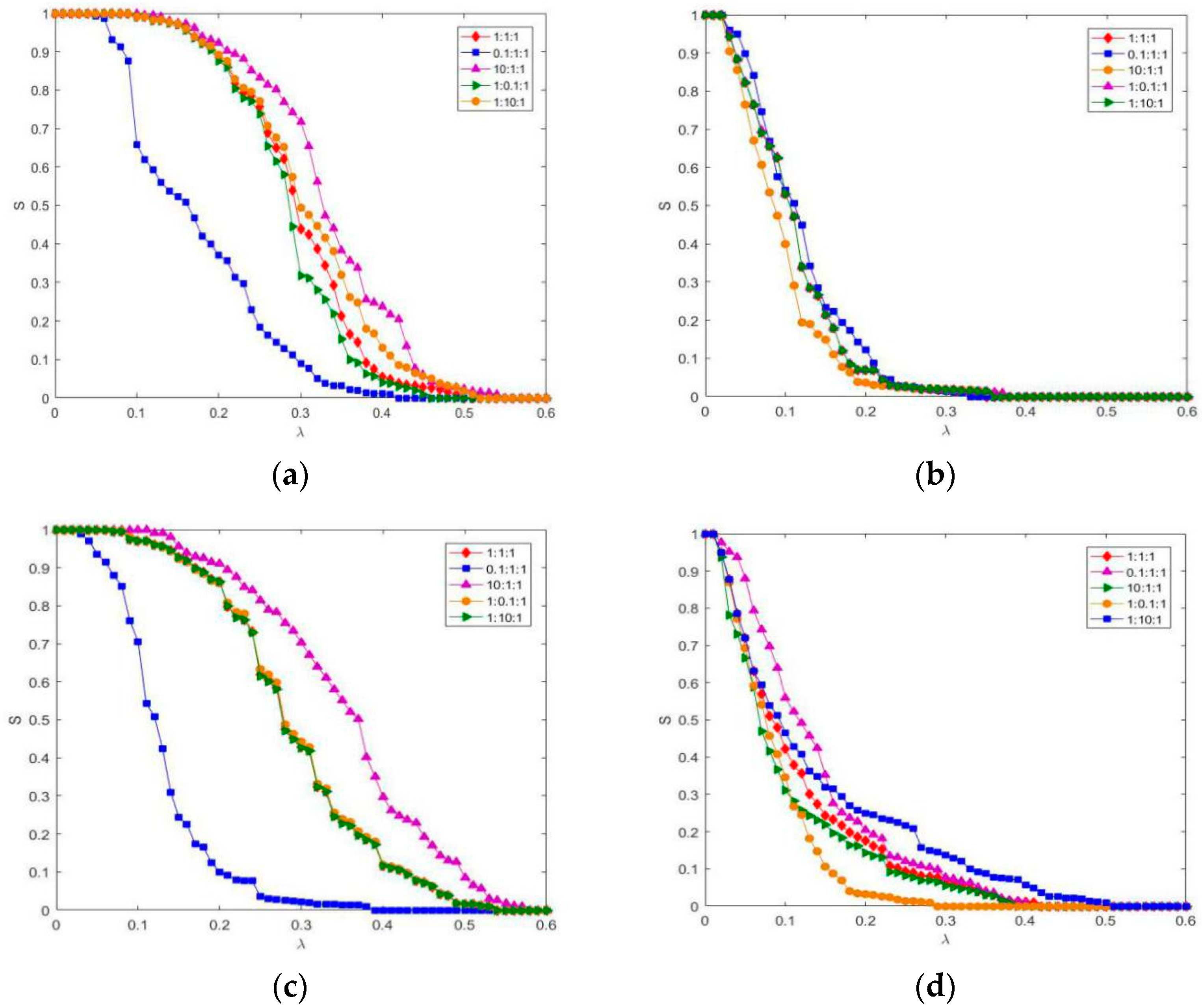
First, we constructed a composite network with the total number of nodes 200 and the average degree 2 of subnets A and B. The coupling relationship between the nodes of the two subnets was established randomly, and the average degree of the coupling relationship was 2. Parameter . When the relationship strength scaling parameter takes different values, the resulting curves are shown in Figure 4.
As the proportion of relationship strength of the intranetwork relationship decreases, the more robust the network is (Figure 4a); conversely, when the proportion of strength of the two relationships increases, network robustness decreases; among them, the relationship has an obvious effect on the network. When its relationship strength is small enough, the network has the strongest robustness. Adjusting the proportion of relationship strength of the intranetwork relationship , shows that the network fault scale changes slightly, indicating that the intranetwork relationship has no effect on a BA-BA composite network (Figure 4b). By reducing the proportion of relationship strength of the intranetwork relationship in the network, network robustness is significantly enhanced (Figure 4c); while the curves of the relationship strength ratio of 1:1:1, 1:0.1:1, and 1:10:1 overlap one other. The relationship has no effect on the network. It shows that in a WS-BA composite network, except the coupling relationship, the size of network failures is affected by the subnets providing dependencies in addition to coupling relationships. Increasing the proportion of relationship strength of the intranetwork relationship will significantly enhance network robustness (Figure 4d); while by increasing or decreasing the proportion of relationship strength of the intranetwork relationship , its curve and the curve of the relationship strength ratio of 1:1:1 coincide. This shows that in a BA-WS composite network, except the coupling relationship, the network fault size is affected by the subnet that is provided with dependencies in addition to the coupling relationship.
3.2. Influence of Coupling Relationship Strength on Composite Networks under Different Conditions of Relationship Topology within the Network
The above experiment mainly explores the influence of the intranetwork relationship on the network. In addition, there is a coupling relationship between subnets. The stronger the coupling relationship is, the more the node is affected by other subnets, and the failure phenomenon that occurs in the network is different. Therefore, in order to explore the influence of the coupling relationship on the network cascading failure under conditions of relationship topology within the network, this paper conducted experiments in different combinations according to the network topologies of WS and BA.
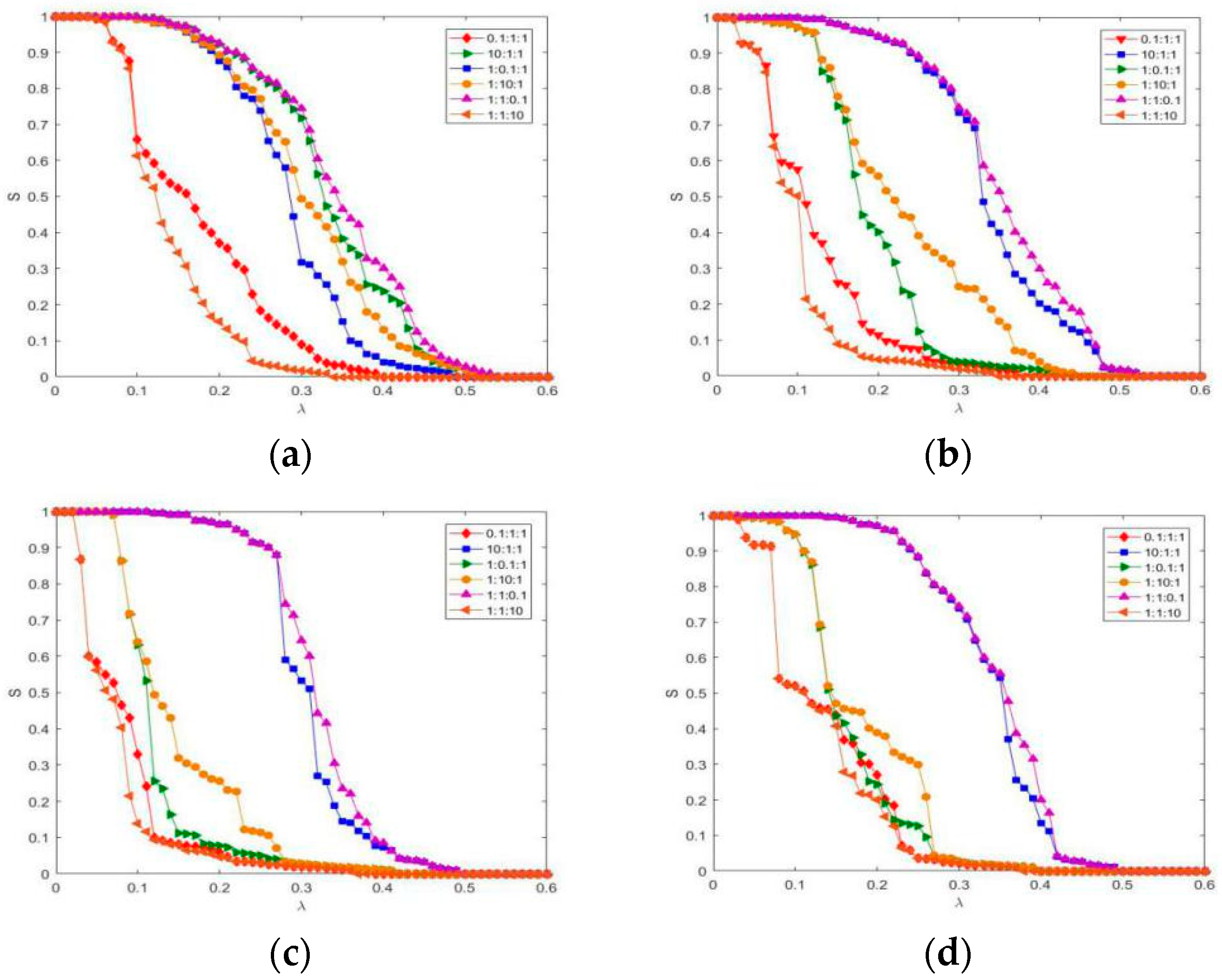
First, we constructed a composite network with the total number of 200 nodes and the average degree 2 of subnets A and B. The coupling relationship between the nodes of the two subnets was established randomly, and the average degree of the coupling relationship was 2. Parameter . When the relationship strength scaling parameter takes different values, the resulting curves are shown in Figure 5.
As shown in Figure 5a,c,d, as the proportion of the coupling relationship increases, the network robustness increases. This indicates that the coupling relationship is beneficial to the network robustness. In Figure 5b, as the proportion of relationship strength of the coupling relationship increases, the network change is small. This indicates that in the BA-BA composite network, the coupling relationship has no effect on the network. Therefore, in order to improve the network’s ability to resist cascading failure, it is necessary to enhance the influence between subnets as much as possible.
3.3. The Average Degree of the Relationship within the Network and Effect of Relationship Strength on Composite Networks under Different Conditions
It has been shown in the literature that the larger the average degree of the network, the more robust the network is. A composite network is composed of multiple subnets, and because each subnet has a different average degree, the cascading failure in a composite network may have different properties under the effect of the relationship strength. The experiments were performed separately in a composite network consisting of subnets with different average degrees for further research.
In the experiment, a composite network with topology WS subnets A and B and 200 subnet nodes was constructed. The parameter of was set to 1. The average degree of the coupling relationship and the coupling relationship establishment were consistent with the above experiments, and the average degree of the subnet was 2, 4, 6. Depending on different combinations, the resulting curve is shown in Figure 6 when the relationship strength scale parameter takes on different values.
In Figure 6, it can be concluded that regardless of the value the average degree of intranetwork relationships takes, the greater the proportion of coupling relationship strength, the more robust the network is. The influence of intranetwork relationships on the network are as follows: In Figure 6a,b, the smaller the proportion of strength of the relationship , the more robust the network is; the curves with the proportion of strength of the relationship of 0.1 and 10 almost overlap. This indicates that when the average degree of the relationship within the subnet B is greater than subnet A, the relationship has no effect on the network. In Figure 6c,d, the smaller the proportion of strength of the relationship , the more robust the network is; the curves of the relationship coincide. This shows that when the average degree of the relationship within the subnet B is less than subnet A, the relationship has no effect on the network. In summary, when the average degree of the lower subnet is greater than the upper subnet, the smaller the proportion of upper subnet relationship strength, and the more robust the network is, and the intranetwork relationship of the lower subnet has no effect on the network. Conversely, the smaller the proportion of relationship strength of the lower subnets, the more robust the network is, and the intranetwork relationship of the upper subnets has no effect on the network.
3.4. The Effect of Relationship Strength on Composite Networks under Different Conditions of Different Average Degree of the Coupling Relationship
The average degree of the coupling relationship represents the strength of coupling between two subnetworks. The greater the average degree of the coupling relationship, the greater the number of edges between the nodes of the two subnetworks. In general, the greater the coupling strength, the more robust the network is, while in composite networks, the edge between nodes has relative strength. The above experiments proved that the relationship strength scaling parameter has a decisive influence on the robustness of the network. In order to investigate the effect of relationship strength on the network under different conditions of coupling relationship average degree, the following experiments were performed.
First, a composite network with a total of 200 nodes and a WS topology for subnets A and B was constructed. was set to 1. The average degree of the intranetwork relationship between the two subnets and was set to 2, and the average degree of the coupling relation was 2, 4, 6, and 8, respectively. The resulting curves are shown in Figure 7 for different values of the relationship strength scaling parameter.
As shown in Figure 7, it can be found that the greater the average degree of the coupling relationship, the closer the curves of the intranetwork relationship and the coupling relationship . When the average degree of the coupling relationship is 8, the curves finally overlap. This indicates that these have the same effect on the network; in addition, as the average degree of the coupling relationship increases, the degree of improvement of the coupling relationship on the network robustness decreases. Therefore, it can be inferred that when the coupling strength is large enough, the coupling relationship has no effect on the network.
4. Discussion and Conclusions
Composite complex networks are widely representative of reality, such as nuclear power networks, logistics–transportation networks, and hydropower-communication networks. The coupling relationship between subnets improves the operational efficiency of the network system on the one hand, and extends the influence of cascading failure on the other hand. The cascading failure model is based on the composite complex network model with multisubnet under load and considers the influence of relationship strength, and the mutual influence of multiple relationships and composite network topology features was studied comprehensively.
In the real world, there are often interdependent relationships between two complex systems. For example, there is a strong interdependence between the power system and the water supply system. The power system provides power services for the water supply system, and the water supply system provides industrial water support for the power system. In order to better describe the interdependent network structure, especially to study the cascading failure and percolation phenomenon, a dependent network model is proposed. The dependent network model provides a good tool for studying the robustness of networks in the real world. In the past, research on cascading failures in complex networks was often limited to one network. However, in the real world, cascading failures will spread to interdependent networks, which will aggravate the diffusion of cascading failures and lead to a sharp decline in network robustness. The emergence of the dependent network model extends the research of cascading failure and robustness of complex networks from one network to two networks, which is more in line with the actual situation of the real world and greatly expands the description ability of complex networks for real complex systems.
The study shows that the two subnetworks in a composite network have different topologies, and the relationship strengths have different effects on the network; the greater the strength of the coupling relationship, the stronger the network robustness, but as the average degree of the coupling relationship increases, the effect of the coupling relationship on the network decreases; when the ratios of the average degree of intranetwork relationships are different, intranetwork relationships have different influences on the network. In a future study, the coupling relationship between two subnets will be changed from unidirectional support to bidirectional dependence to further investigate cascading failure in a composite complex network.
Author Contributions
All authors contributed to the work in this paper. S.B., G.S. and C.-C.C. designed the research and wrote the paper. G.S. participated in the creation of the graphics. All authors have read and agreed to the published version of the manuscript.
Funding
This research was funded by Shandong Provincial Natural Science Foundation, China, grant number ZR2017MG011.
Institutional Review Board Statement
Not applicable.
Informed Consent Statement
Not applicable.
Data Availability Statement
Not applicable.
Conflicts of Interest
The authors declare no conflict of interest.
References
- Rosato, V.; Issacharoff, L.; Tiriticco, F.; Meloni, S.; De Porcellinis, S.; Setola, R. Modelling interdependent infrastructures using interacting dynamical models. Int. J. Crit. Infrastruct. 2008, 4, 63–79. [Google Scholar] [CrossRef]
- Sun, G.X.; Bin, S. Router-Level Internet Topology Evolution Model based on Multi-Subnet Composited Complex Network Model. J. Internet Technol. 2017, 18, 1275–1283. [Google Scholar]
- Agrawal, V.K.; Baba, K.V.S.; Narasimhan, S.R. Enhancing resilience of the North Indian Power System against pollution and foggy weather—An Experience. J. Int. Assoc. Electr. Gener. Transm. Distrib. 2017, 30, 33–39. [Google Scholar]
- Carreras, B.A.; Reynolds, B.; José, M. Critical behavior of power transmission network complex dynamics in the OPA model. Chaos 2019, 29, 033103. [Google Scholar] [CrossRef]
- Dobson, I.; Carreras, B.A.; Newman, D.E. A loading-dependent model of probabilistic cascading failure. Probab. Eng. Inf. Sci. 2005, 19, 15–32. [Google Scholar] [CrossRef] [Green Version]
- Bak, P.; Tang, C.; Wiesenfeld, K. Self-organized criticality: An explanation of the 1/fnoise. Phys. Rev. Lett. 1987, 59, 381–384. [Google Scholar] [CrossRef]
- Wang, L.; Fu, Y.; Chen, M.Z.Q.; Yang, X. Controllability robustness for scale-free networks based on nonlinear load capacity. Neurocomputing 2017, 251, 99–105. [Google Scholar] [CrossRef]
- Kinney, R.; Crucitti, P.; Albert, R.; Latora, V. Modeling cascading failures in the North American power grid. Eur. Phys. J. B 2005, 46, 101–107. [Google Scholar] [CrossRef]
- Wang, X.J.; Guo, S.Z.; Jin, L.; Chen, M.; Juan, W.X.; Ze, G.S.; Mo, C.; Lei, J. Cascading failures mechanism based on betweenness-degree ratio distribution with different connecting preferences. Int. J. Mod. Phys. C 2017, 28, 1750052. [Google Scholar] [CrossRef]
- Guo, J.; Xu, J.; He, Z.; Liao, W. Simulation Study on Cascading Failure of Multimodal Transport Network. J. Adv. Transp. 2020, 2020, 1–9. [Google Scholar] [CrossRef]
- Motter, A.E.; Lai, Y.-C. Cascade-based attacks on complex networks. Phys. Rev. E 2002, 66, 065102. [Google Scholar] [CrossRef] [Green Version]
- Crucitti, P.; Latora, V.; Marchiori, M. Model for cascading failures in complex networks. Phys. Rev. E 2004, 69, 045104. [Google Scholar] [CrossRef] [Green Version]
- Buldyrev, S.V.; Parshani, R.; Paul, G.; Stanley, H.E.; Havlin, S. Catastrophic cascade of failures in interdependent networks. Nat. Cell Biol. 2010, 464, 1025–1028. [Google Scholar] [CrossRef] [Green Version]
- Huang, X.; Gao, J.; Buldyrev, S.V.; Havlin, S.; Stanley, H.E. Robustness of interdependent networks under targeted attack. Phys. Rev. E 2011, 83, 065101. [Google Scholar] [CrossRef] [Green Version]
- Junde, W.; Songyang, L.; Yirun, R. Research on the Robustness of Interdependent Networks under Localized Attack. Appl. Sci. 2017, 7, 597–610. [Google Scholar]
- Gao, Y.-L.; Chen, S.-M.; Nie, S.; Ma, F.; Guan, J.-J. Robustness analysis of interdependent networks under multiple-attacking strategies. Phys. A Stat. Mech. Appl. 2018, 496, 495–504. [Google Scholar] [CrossRef]
- Zhao, D.; Wang, Z.; Xiao, G.; Gao, B.; Wang, L. The robustness of interdependent networks under the interplay between cascading failures and virus propagation. Euro. Phys. Lett. 2016, 115, 58004. [Google Scholar] [CrossRef] [Green Version]
- Chen, Z.; Du, W.-B.; Bin Cao, X.; Zhou, X.-L. Cascading failure of interdependent networks with different coupling preference under targeted attack. Chaos Solitons Fractals 2015, 80, 7–12. [Google Scholar] [CrossRef]
- Wang, J.; Jiang, C.; Qian, J. Robustness of interdependent networks with different link patterns against cascading failures. Phys. A Stat. Mech. Appl. 2014, 393, 535–541. [Google Scholar] [CrossRef]
- Dong, Z.; Fang, Y.; Tian, M.; Zhang, R. Approaches to improve the robustness on interdependent networks against cascading failures with load-based model. Mod. Phys. Lett. B 2015, 29, 1550210. [Google Scholar] [CrossRef]
- Shao, S.; Huang, X.; Stanley, H.E.; Havlin, S. Robustness of a partially interdependent network formed of clustered networks. Phys. Rev. E 2014, 89, 032812. [Google Scholar] [CrossRef] [Green Version]
- Cheng, Z.; Cao, J. Cascade of failures in interdependent networks coupled by different type networks. Phys. A Stat. Mech. Appl. 2015, 430, 193–200. [Google Scholar] [CrossRef]
- Fu, G.; Dawson, R.; Khoury, M.; Bullock, S. Interdependent networks: Vulnerability analysis and strategies to limit cascading failure. Eur. Phys. J. B 2014, 87, 148. [Google Scholar] [CrossRef] [Green Version]
- Min, B.; Yi, S.D.; Lee, K.-M.; Goh, K.-I. Network robustness of multiplex networks with interlayer degree correlations. Phys. Rev. E 2014, 89, 042811. [Google Scholar] [CrossRef] [Green Version]
- Shin, D.-H.; Qian, D.; Zhang, J. Cascading effects in interdependent networks. IEEE Netw. 2014, 28, 82–87. [Google Scholar] [CrossRef]
- Bin, S.; Sun, G.; Cao, N.; Qiu, J.; Zheng, Z.; Yang, G.; Zhao, H.; Jiang, M.; Xu, L. Collaborative Filtering Recommendation Algorithm Based on Multi-Relationship Social Network. Comput. Mater. Contin. 2019, 60, 659–674. [Google Scholar] [CrossRef] [Green Version]
Figure 1.
An example of composite complex network.

Figure 2.
Cascading failure of a coupling network.

Figure 3.
Cascading failure of a composite network.

Figure 4.
Influence of intranetwork relationship strength on composite networks. (a) WS-WS (Two subnets are WS network); (b) BA-BA (Two subnets are BA network); (c) WS-BA (The first subnet is WS network and the second subnet is BA network); (d) BA-WS (The first subnet is BA network and the second subnet is WS network).

Figure 5.
Influence of coupling relationship strength on composite networks. (a) WS-WS (Two subnets are WS network); (b) BA-BA (Two subnets are BA network); (c) WS-BA (The first subnet is WS network and the second subnet is BA network); (d) BA-WS (The first subnet is BA network and the second subnet is WS network).

Figure 6.
The average degree of the relationship on composite networks. (a) The average degree of intranetwork relationships is 2 and 4; (b) the average degree of intranetwork relationships is 2 and 6; (c) the average degree of intranetwork relationships is 4 and 2; (d) the average degree of intranetwork relationships is 6 and 2.

Figure 7.
The effect of relationship strength on composite networks. (a) The average degree of coupling relationship is 2; (b) the average degree of coupling relationship is 4; (c) the average degree of coupling relationship is 6; (d) the average degree of coupling relationship is 8.
Figure 7.
The effect of relationship strength on composite networks. (a) The average degree of coupling relationship is 2; (b) the average degree of coupling relationship is 4; (c) the average degree of coupling relationship is 6; (d) the average degree of coupling relationship is 8.


Table 1.
Symbols in the cascading failure model of composite networks.
| Symbols | Explanation |
|---|---|
| The relationship on edge | |
| The degree of node about relationship | |
| The initial load of node | |
| The relationship set between the failed node and its neighbor nodes | |
| The set of neighbor nodes of node about relationship | |
| The relationship strength of relationship | |
| The number of triangles constituted by edges according to the relationship | |
| The importance of node about relationship | |
| The load of the relationship from node to node | |
| The number of failed nodes caused by node |
Publisher’s Note: MDPI stays neutral with regard to jurisdictional claims in published maps and institutional affiliations. |
© 2021 by the authors. Licensee MDPI, Basel, Switzerland. This article is an open access article distributed under the terms and conditions of the Creative Commons Attribution (CC BY) license (http://creativecommons.org/licenses/by/4.0/).
Share and Cite
MDPI and ACS Style
Sun, G.; Chen, C.-C.; Bin, S. Study of Cascading Failure in Multisubnet Composite Complex Networks. Symmetry 2021, 13, 523. https://0-doi-org.brum.beds.ac.uk/10.3390/sym13030523
AMA Style
Sun G, Chen C-C, Bin S. Study of Cascading Failure in Multisubnet Composite Complex Networks. Symmetry. 2021; 13(3):523. https://0-doi-org.brum.beds.ac.uk/10.3390/sym13030523
Chicago/Turabian StyleSun, Gengxin, Chih-Cheng Chen, and Sheng Bin. 2021. "Study of Cascading Failure in Multisubnet Composite Complex Networks" Symmetry 13, no. 3: 523. https://0-doi-org.brum.beds.ac.uk/10.3390/sym13030523
Note that from the first issue of 2016, this journal uses article numbers instead of page numbers. See further details here.