Article

A Novel Closed-Loop Control Method for Li-Ion Batteries Connected in Series Power Supply Based on the Time Sequences Recalculation Algorithm

1
Institute of Electrical Engineering, Chinese Academy of Sciences, Beijing 100190, China
2
Key Laboratory of Power Electronics and Electric Drive, Chinese Academy of Sciences, Beijing 100190, China
3
School of Electronic, Electrical and Communication Engineering, University of Chinese Academy of Sciences, Beijing 100049, China
*
Author to whom correspondence should be addressed.
Submission received: 29 May 2021 / Revised: 12 July 2021 / Accepted: 13 July 2021 / Published: 10 August 2021
(This article belongs to the Special Issue Research on Motor and Special Electromagnetic Device of Symmetry)

Abstract

:
The charging time of Li-ion batteries connected in series (LBCSs) power supply is the main concern in an electromagnetic propulsion system. However, the capacity loss of a Li-ion battery is inevitable due to the repetitive operation of LBCSs power supply, which leads to the decrease in the average current. Thus, the voltages of symmetrically distributed pulse capacitors of LBCSs power supply will not reach the setting value in the specified time. This paper proposes a novel closed-loop control method to solve the problem. By collecting the pulse capacitor voltage and the circuit current, the time sequences of Li-ion batteries are recalculated in real time in a closed-loop to increase the average current. The time-domain model of the circuit topology of the LBCSs power supply and an innovative closed-loop control method based on the time sequences recalculation algorithm are described first. Then, the circuit model is built in PSIM for simulation analyses. Finally, a series of experiments are conducted to confirm the effectiveness of the method on the megawatt LBCSs power supply platform. Both the simulation and experimental results validate that the proposed method not only shortens the charging time, but also increases the average current. In practical experiments, the charging time is shortened by 4.5% and the average current is increased by 4.8% using the proposed method at the capacity loss of 50 V.

1. Introduction

With the rapid development of laser emission technology, electromagnetic propulsion and plasma science, the high-voltage power supply (HPS) has attracted a great deal of attention [1,2,3,4]. At present, the commonly used circuits of HPS in the electromagnetic propulsion system include the series resonant circuit, the buck circuit and the batteries connected in series (BCSs) circuit, as shown in Figure 1. Though the series resonant circuit is mature in technology, it still needs to be used in parallel to increase the power in the electromagnetic propulsion system, resulting in a large volume. The buck circuit is small in size, but it is difficult to satisfy the requirements of high frequency, high voltage and large current at the same time. The BCSs circuit was first proposed by the Naval University of Engineering, which had the advantages of high power density and high energy density. In recent years, the BCSs circuit has developed towards miniaturization, lightweight and repetitive operation. As a result, its research has great potential in the electromagnetic propulsion system.
The BCSs power supply usually consists of the battery, the power electronic device, the resistor, the inductor, and the pulse capacitor [5,6,7]. As a primary energy storage unit, the battery reduces the demand from the grid power greatly and provides the energy continuously in the meantime. Due to the various advantages, such as high-power densities, no memory effects, and long service lives, Li-ion batteries are widely used in the repetitive operation of LBCSs power supply. At present, the research focus of cathode materials of Li-ion batteries is still mainly on the layered lithium transition metal oxide LiMO2 (M = Co, Ni, Mn, etc.), spinel LiMn2O4 and olivary LiMPO4 (M = Fe, Mn), while the research about anode materials of Li-ion batteries mainly includes coke, graphite, mesophase carbon microspheres, pyrolytic carbon materials, tin-based materials, lithium transition metal oxides and some other transition metal oxides. However, the performance of the Li-ion battery declines with time due to the degradation of its electrochemical components, which leads to capacity loss. Compared with the state of charge (SOC) estimation and the state of health (SOH) estimation in the Li-ion battery management system (BMS), the closed-loop control method is also a key research of LBCSs power supply after the capacity loss of the Li-ion battery.
Wu et al. [8] studied the reasons for restricting the charging time in BCSs power supply. By optimizing the impedance and inductance, the charging time was effectively shortened. Li et al. [9] proposed a scheduling series strategy to improve the efficiency of BCSs power supply. The circuit of parallel structure was used to charge the capacitor first. When the capacitor voltage reached the voltage of series batteries, the structure of the circuit was changed from a parallel connection to a series connection. This method reduced the volume, the weight and the cost of the system. Liu et al. [10,11] carried out research on BCSs power supply with ten batteries, and set the same intervals for the batteries to charge the pulse capacitor. The results showed that the power supply can work effectively. Based on the analysis of the problem of charge with low accuracy caused by distribution parameters in the circuit, Long et al. [12,13] put forward the sequential reconstruction strategy to satisfy the demand of a quick and accurate charge. However, the above studies did not consider the capacity loss of the battery. In this paper, Li-ion batteries are used as the primary energy source, and a novel closed-loop control method for LBCSs power supply based on the time sequences recalculation algorithm is proposed. Considering the Li-ion battery capacity loss of LBCSs power supply in the repetitive operation, the problem that the voltages of symmetrically distributed pulse capacitors cannot reach the setting value in the specified time is mainly studied and analyzed. Finally, it is clear that the proposed method can shorten the charging time and increase the average current, which makes the voltages of symmetrically distributed pulse capacitors of LBCSs power supply reach the setting value in the specified time in the repetitive operation.
The paper is organized as follows. In Section 2, the circuit topology and operation principles of LBCSs power supply are introduced. Then, the time-domain model of the circuit topology is established, and a novel closed-loop control method based on the time sequences recalculation algorithm is derived. In Section 3 and Section 4, the performance of the proposed method is validated with simulations and experiments. The results and discussion are given. Finally, Section 5 concludes this paper.

2. Modeling and Closed-Loop Control Method

The module of LBCSs, the loads, and the controller are the main parts of LBCSs power supply. In the module of LBCSs, a group of the module is composed of a battery, an insulated gate bipolar transistor (IGBT), and a flywheel diode. By connecting several groups in series, the module of LBCSs is built [14,15]. Figure 2 shows the circuit topology of LBCSs power supply, here E1~En represent the Li-ion batteries (E1~En = e), R0 represents the resistor of batteries, L0 represents the inductor of batteries, D1~Dn represent the flywheel diodes, L represents the inductor of the loads, R represents the resistor of the loads, and C1~Cn represent the symmetric pulse capacitors of the loads (C1~Cn = C).
Figure 2 is taken as an example to explain the operation principles of LBCSs power supply. The IGBT S1 in the first group of the module was first switched on. Then, the Li-ion battery E1 started charging one of the symmetrically distributed pulse capacitors C1. When the pulse capacitor voltage reached the proper value, the Li-ion battery E2 was connected in series to the circuit according to time sequences by switching on S2. As the rest of the Li-ion batteries were connected in series, the pulse capacitor voltage increased rapidly. When the voltage reached the voltage setting value, the IGBTs were switched off to end the charging process [8], as shown in Figure 3. In the next charging process, the pulse capacitor C2 also works alone. The entire charging process was not over until the last pulse capacitor voltage reached the setting value.

2.1. Modeling of the Circuit

The circuit topology can be simplified to the equivalent circuit, as shown in Figure 4. Referring to the circuit analysis and considering the saturation voltage of the IGBT (UIGBT) and the forward voltage of the diode (UD), the voltage balance equation of the equivalent circuit can be expressed if the next Li-ion battery is connected at tn−1:
L n C d 2 U C d t 2 + C R n d U C d t + U C = E
where
R n = n R 0 + R
L n = n L 0 + L
E = n e n U IGBT ( N n ) U D
where N indicates the total number of Li-ion batteries, and n represents the number of LBCSs. The characteristic equation of homogeneous linear differential equation with constant coefficients is expressed by the following:
L n C P 2 + C R n P + 1 = 0
If the circuit parameters satisfy the requirement of the over-damped condition ( R n > 2 L n / C ), the pulse capacitor voltage and the circuit current can be expressed as:
U C ( t ) = A 1 e P 1 ( t t n - 1 ) + A 2 e P 2 ( t t n - 1 ) + E
I ( t ) = C ( A 1 P 1 e P 1 ( t t n - 1 ) + A 2 P 2 e P 2 ( t t n - 1 ) )
where
P 1 = R n 2 L n + ( R n 2 L n ) 2 1 L n C
P 2 = R n 2 L n ( R n 2 L n ) 2 1 L n C
A 1 = P 2 U ( t n - 1 ) E P 2 I ( t n - 1 ) / C P 2 P 1
A 2 = P 1 U ( t n - 1 ) E P 1 I ( t n - 1 ) / C P 1 P 2
U(tn−1) represents the pulse capacitor voltage at tn−1 and I(tn−1) represents the circuit current at tn−1. If the circuit parameters satisfy the requirement of the under-damped condition ( R n < 2 L n / C ), the pulse capacitor voltage and the circuit current can be expressed as:
U C ( t ) = 2 e δ ( t t n - 1 ) [ k 1 cos ω ( t t n - 1 ) k 2 sin ω ( t t n - 1 ) ] + E
I ( t ) = 2 C e δ ( t t n - 1 ) [ ( δ k 1 k 2 ω ) cos ω ( t t n - 1 ) + ( δ k 2 k 1 ω ) sin ω ( t t n - 1 ) ]
where
δ = R n 2 L n
ω = 1 L n C ( R n 2 L n ) 2
k 1 = U ( t n - 1 ) E 2
k 2 = I ( t n - 1 ) / C + δ ( U ( t n - 1 ) + E ) 2 ω

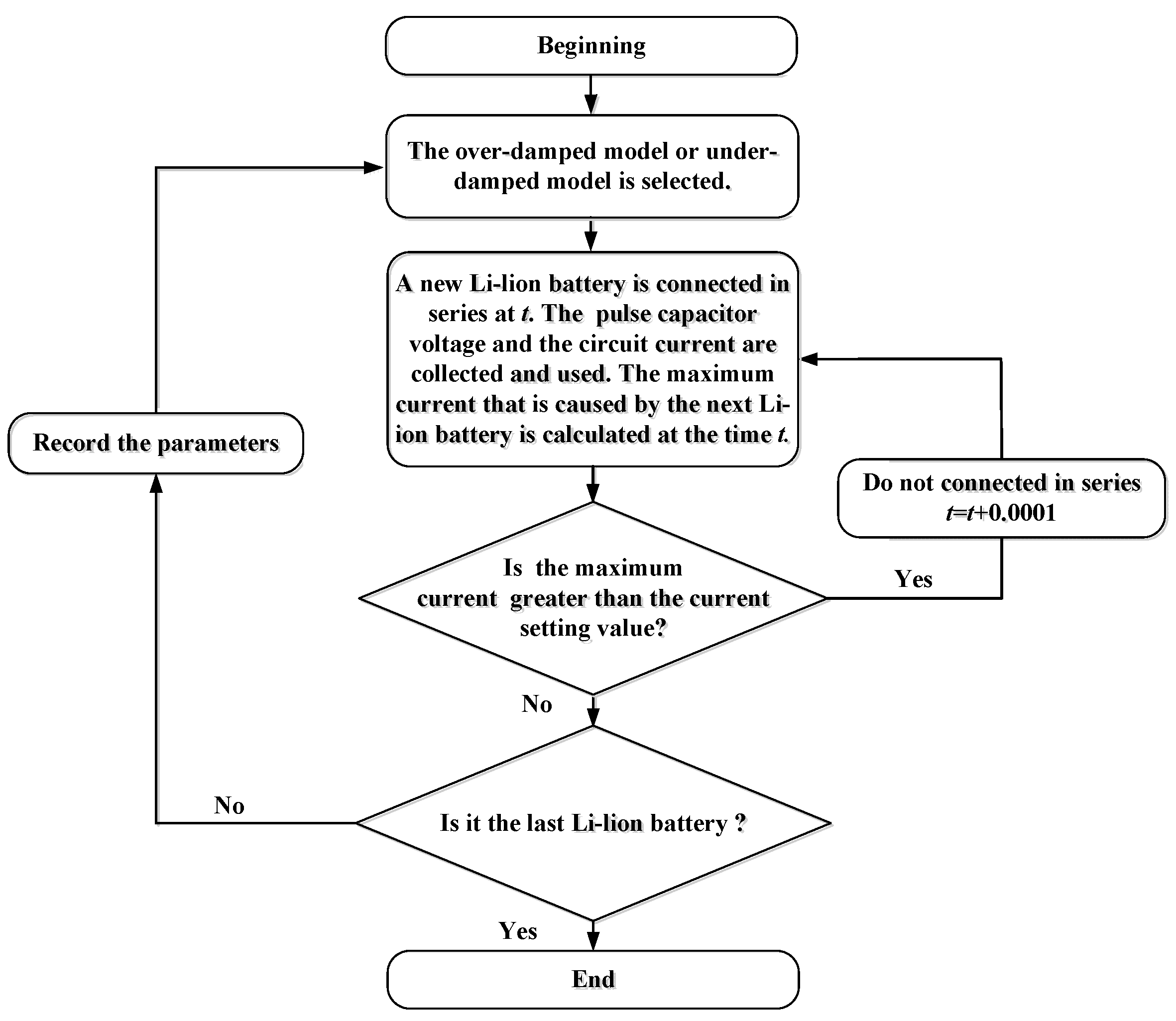
2.2. Closed-Loop Control Method Based on the Time Sequences Recalculation Algorithm

The principle of the closed-loop control method based on the time sequences recalculation algorithm was to shorten the charging time and increase the average current by recalculating the time sequences, which are closely related to the current Li-ion battery voltage and the next Li-ion battery voltage. The load voltage E, the pulse capacitor voltage U(tn−1) and the circuit current I(tn−1) were collected and used to calculate the current Li-ion battery voltage e to reduce the error caused by the capacity loss, while the reference voltage eref was still used by the next Li-ion battery. According to the equivalent circuit in Figure 4, the load voltage E was calculated in (18). Therefore, the proposed method can be realized by collecting and using the pulse capacitor voltage and the circuit current.
E = L d I ( t ) d t + I ( t ) R n + U C ( t )
The proposed method was applied to the LBCSs power supply. Moreover, the maximum current generated by each Li-ion battery could not exceed the current setting value. Hence, the time to reach the maximum current needed to be calculated. The solution can be simplified by finding the derivative of t in Formulas (7) and (13). Then, the times were given as follows:
t m = ln A 1 P 1 2 A 2 P 2 2 P 2 P 1 + t n + 1
t m = 1 ω arctan ( δ 2 ω 2 ) k 1 + 2 δ ω k 2 ( δ 2 ω 2 ) k 2 2 δ ω k 1 + t n + 1
Figure 5 shows the flowchart of time sequences recalculation algorithm. Firstly, the over-damped model or under-damped model was selected according to the circuit parameters. Meanwhile, the maximum current (Imax) that was caused by the first Li-ion battery and the time of reaching Imax were calculated. Then, a new Li-ion battery was connected in series at t. The pulse capacitor voltage and the circuit current were collected to calculate an accurate Li-ion battery voltage e. Finally, the maximum current that was caused by the next Li-ion battery was calculated at the time t. If the maximum current is greater than the current setting value, the process should be repeated after the time t. However, time will be saved as a time sequence for the new Li-ion battery and the algorithm will go to the next cycle if the maximum current is exactly equal to the current setting value.

3. Simulation

According to the time-domain model of the circuit topology and the closed-loop control method based on the time sequences recalculation algorithm of Section 2, the simulation model was established in the simulation software PSIM. The simulation analyses of the constant voltage mode, the capacity loss mode and the time sequences recalculation mode are carried out.

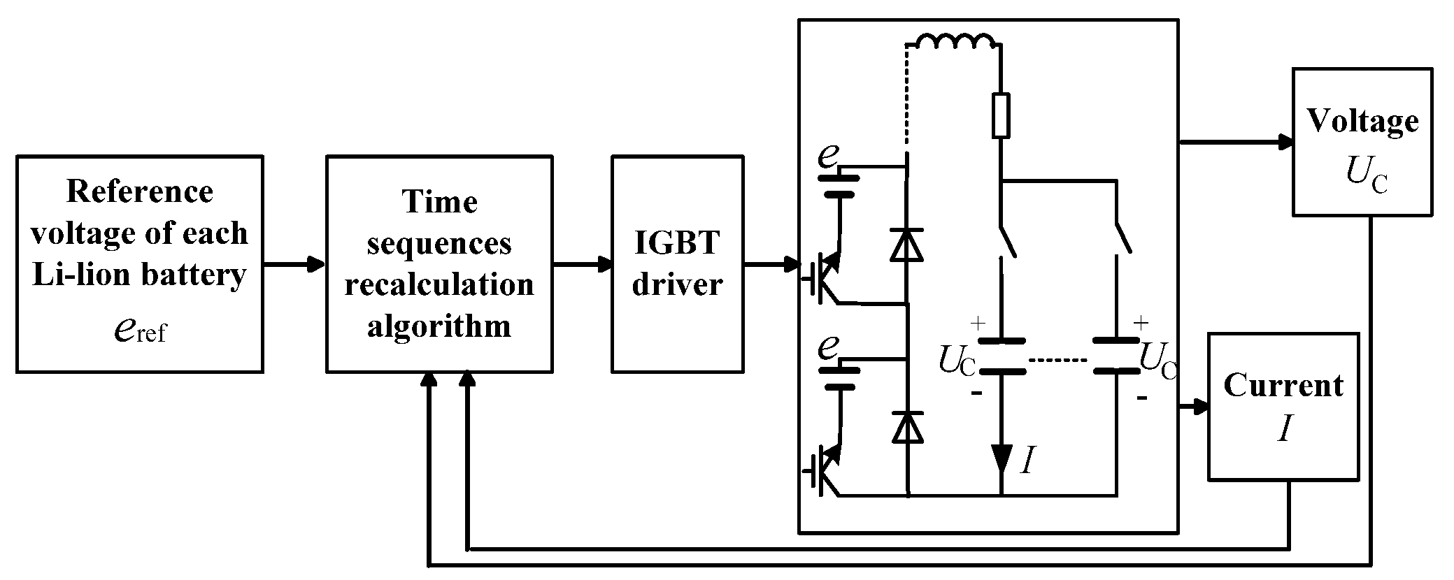
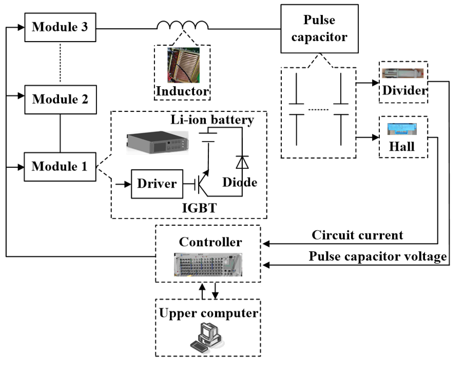
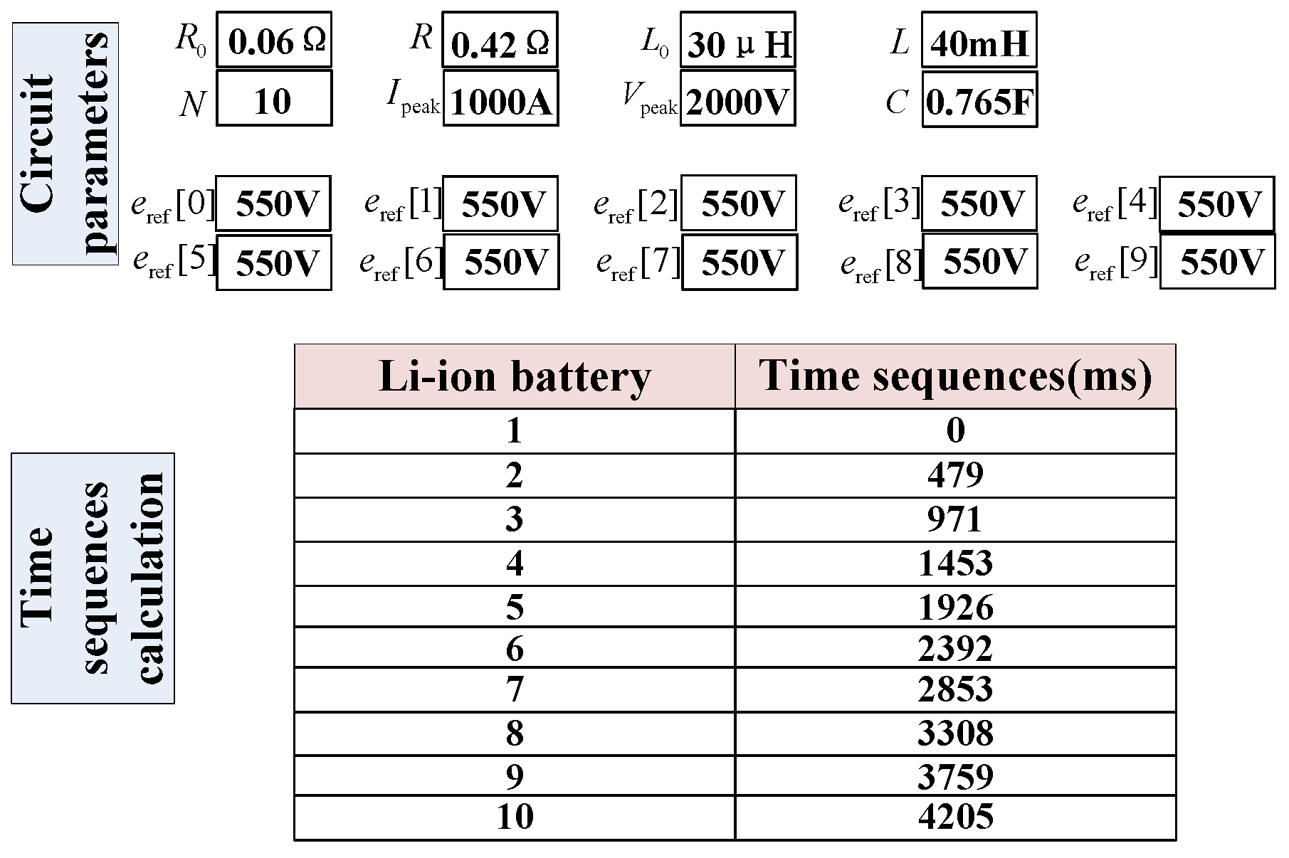
3.1. Simulation Model

Figure 6 shows the block diagrams of the proposed method. The time sequences of the Li-ion batteries were calculated by using the reference voltage eref of each Li-ion battery. Then, the pulse capacitor voltage and the circuit current were used to recalculate the time sequences in a closed-loop in the simulation. Meanwhile, the time sequences were sent to the driver of IGBTs to control the series connection of Li-ion batteries, providing that the reference voltage eref is 550 V in the simulation. The constant voltage mode represents that the voltages (e = 550 V) were constant when the Li-ion batteries charged the pulse capacitor, while the capacity loss mode means that the voltages decreased (e = 500 V) in the state of charging the last pulse capacitor Cn. Neither the constant voltage mode nor the capacity loss mode adopted the proposed method. The time sequences recalculation mode was used to adjust the time sequences of the Li-ion batteries in real time by using the proposed method after the voltages were decreased (e = 500 V). Values of the circuit parameters in the simulation are given in Table 1. The simulation started at t = 0, and its step was 100 μs.

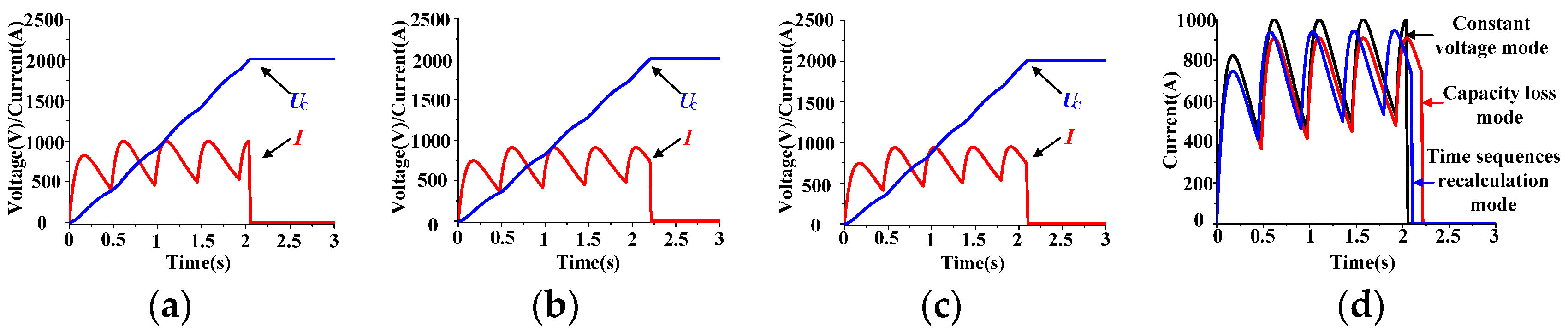
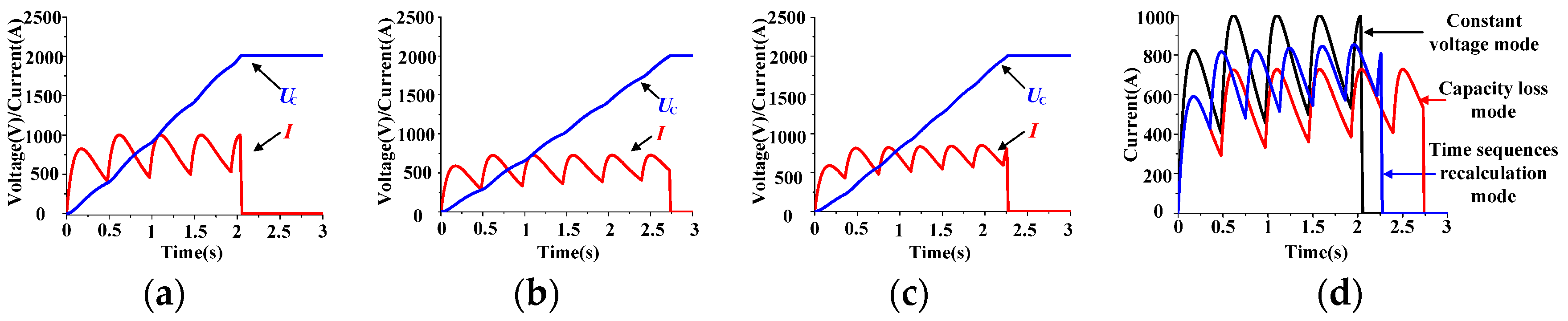
3.2. Simulation Analyses

Simulation waveforms of the pulse capacitor voltage and the circuit current are shown in Figure 7. From the comparison results of Table 2, the conclusion can be drawn that the proposed method shortened the charging time and increased the average current after the Li-ion battery capacity loss in LBCSs power supply. Compared with the capacity loss mode, the charging time of the time sequences recalculation mode was shortened by 5.1% and the average current was increased by 5.4% at the capacity loss of 50 V. With the addition of the method, the voltages of symmetrically distributed pulse capacitors of LBCSs power supply reached the voltage setting value in the specified time, which can satisfy the requirement of quick charge in the electromagnetic propulsion system. In addition, the conclusion is also valid when the capacity loss was less than 50 V.
It can be seen in Figure 7 that the maximum current generated by each Li-ion battery did not reach the setting value by using the proposed method. Meanwhile, the time sequences recalculation model did not outperform the constant voltage mode as shown in Table 2. The reason is that the reference voltage eref of the Li-ion battery was inconsistent with the actual value e. However, the Li-ion battery voltage could not be predicted in real time, as it was necessary to set the eref for the closed-loop control before charging. Providing that eref was 500 V in the simulation, waveforms of the pulse capacitor voltage and the circuit current under this condition by using the proposed method can be shown in Figure 8. It can be discerned from Figure 8 that the time sequences of Li-ion batteries were 0 s~0.378 s~0.794 s~1.204 s~1.609 s, the pulse capacitor voltage reached the voltage setting value at t = 1.924 s, and the average current was 795.1 A. In addition, the maximum current generated by each Li-ion battery reached the current setting value. Compared with the simulation results of the constant voltage mode in Table 2, the charging time was shortened and the average current was increased in the time sequences recalculation model in Figure 8. However, the eref could only be estimated based on the battery state and set in advance for the time sequences calculation; the simulation results shown in Figure 8 are currently not available. The proposed method did not make the maximum current reach the current setting value and the time sequences recalculation model did not outperform the constant voltage mode, but it still adjusted the time sequences under the condition of the Li-ion battery capacity loss, which validates the effectiveness of LBCSs power supply in the repetitive operation.
The rated voltage of the Li-ion battery was 550 V, and the discharge cut-off voltage was 400 V. When the capacity loss of the Li-ion battery is 150 V (e = 550 V), the proposed method can be added. Simulation waveforms of the pulse capacitor voltage and the circuit current are shown in Figure 9. It can be seen in Table 3 that the charging time was shortened by 17.2% and the average current was increased by 20.8% using the proposed method. As is well known, that over-discharge may bring catastrophic consequences to the Li-ion battery, especially a large current over-discharge or a repeated over-discharge will have a greater impact on the battery. Generally speaking, over-discharge will increase the internal pressure of the battery, destroy the reversibility of the cathode and anode active materials and increase the battery resistance. Even if the Li-ion battery is recharged, it can only partially recover, and its life will be greatly shortened. Therefore, the Li-ion battery capacity loss was set to 50 V in the experiment.

4. Experiment

4.1. Experimental Design Introduction

To further validate the effectiveness of the closed-loop control method based on the time sequences recalculation algorithm, a series of experiments were carried out on the megawatt LBCSs power supply platform. As shown in Figure 10, the high voltage divider converted the pulse capacitor voltage into a low-voltage signal. Meanwhile, the hall element collected the circuit current and converted it into an electrical signal. Then, these two signals were uploaded to the controller. The controller received the time sequences of Li-ion batteries that were calculated by the circuit parameters in the upper computer before the experiments, as shown in Figure 11. Additionally, it recalculated the time sequences by using the pulse capacitor voltage and the circuit current collected in real time during the experiments. Finally, the time sequences were given to the driver of IGBTs to control the series connection of the Li-ion batteries to the circuit.

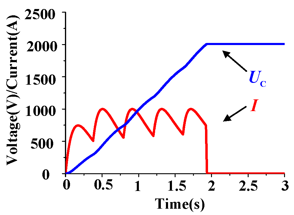
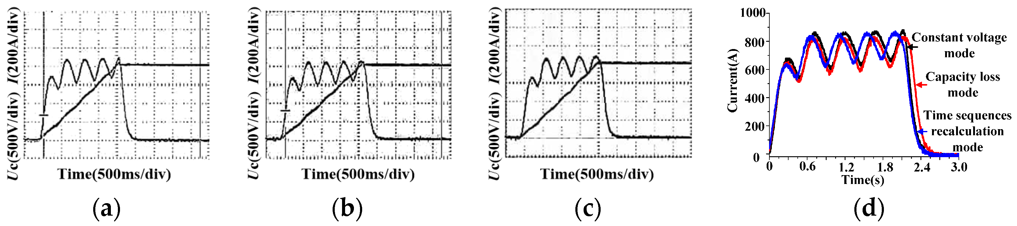
4.2. Experimental Analyses

The experiments started at t = 0. Figure 12 shows the experimental waveforms of the pulse capacitor voltage and the circuit current. It can be seen in Table 4 that the charging time was shortened by 4.5% and the average current was increased by 4.8% using the proposed method at the Li-ion battery capacity loss of 50 V. Concluding from the experimental results, the maximum current did not reach 1000 A when the Li-ion batteries were connected to the circuit. One of the reasons was the capacity loss of the next Li-ion battery in the charging process. Another reason comes from the inductor, which is made of copper. In the large current experiments, the heat and temperature of the inductor gradually increased with time, resulting in the increase in the resistance. Hence, the average current decreased. Additionally, the equivalent resistance of each Li-ion battery changed with the different discharge rates of the Li-ion battery. All these were the factors why the maximum current of the experimental circuit was less than 1000 A. However, it can be discerned from Table 4 that these factors had little effect on the charging time. The experimental time sequences were 0 s~0.398 s~0.892 s~1.303 s~1.720 s, while the simulation time sequences were 0 s~0.443 s~0.905 s~1.355 s~1.796 s of the proposed method. Compared with the simulation results, the charging time error was 0.6% and the average current error was 4.4% for the experimental results. This is due to the fact that the pulse capacitor voltage and the circuit current collected were relatively small in the experiments, which was caused by the above factors. However, the experimental waveforms basically met the expectation, which made the voltages of symmetrically distributed pulse capacitors LBCSs power supply reach the setting value in the specified time in the repetitive operation. The practicability of the proposed method was verified again, which is worthy of popularization in the electromagnetic propulsion system.

5. Conclusions

In this paper, a novel closed-loop control method for LBCSs power supply based on the time sequences recalculation algorithm was proposed, which was used to solve the problem that the voltages of symmetrically distributed pulse capacitors cannot reach the set value due to the capacity loss of the Li-ion battery in the repetitive operation of electromagnetic propulsion. The proposed method adjusted the time sequences of Li-ion batteries in the closed-loop and shortened the charging time of LBCSs power supply. Meanwhile, the average current was increased by collecting and using the pulse capacitor voltage and the circuit current in real time, which can satisfy the requirement that the voltages of symmetrically distributed pulse capacitors reached the current setting value in the specified time. In addition, the simulation results and experimental results both exhibited the advantages of the proposed method, which has already been applied to project practice. The results provide a solid foundation for the future development of electromagnetic propulsion devices, especially in the national defense construction.

Author Contributions

Conceptualization, Q.T. and Y.G.; methodology, Q.T.; software, K.L.; validation, Q.T., K.L. and X.X.; formal analysis, Q.T.; investigation, Q.T.; resources, Q.T.; data curation, Q.T.; writing—original draft preparation, Q.T.; writing—review and editing, Y.G., Y.S. and P.Y.; visualization, X.X.; supervision, Q.T., Y.G. and Y.S.; project administration, Y.S.; funding acquisition, Q.T. All authors have read and agreed to the published version of the manuscript.

Funding

This research received no external funding.

Institutional Review Board Statement

Not applicable.

Informed Consent Statement

Not applicable.

Data Availability Statement

The data used in the study are available from the authors upon reasonable request.

Conflicts of Interest

The authors declare no conflict of interest.

References

  1. Zhao, Q.; Li, S.; Cao, R.; Wang, D.; Yuan, J. Design of Pulse Power Supply for High-Power Semiconductor Laser Diode Arrays. IEEE Access 2019, 7, 92805–92812. [Google Scholar] [CrossRef]
  2. He, Y.; Guan, Y.; Song, S. Design of a Multi-Turn Railgun for Accelerating Massive Load to High Speed. IEEE Trans. Plasma Sci. 2019, 47, 4181–4183. [Google Scholar] [CrossRef]
  3. Toshihiko, N.; Hafidz, E.; Ryota, K.; Kazuki, S. Development of High-speed and High-Voltage Pulse Generator for NOX Decomposition Plasma Reactor. In Proceedings of the 2017 IEEE 12th International Conference on Power Electronics and Drive Systems, Honolulu, HI, USA, 12–15 December 2017; pp. 1080–1085. [Google Scholar]
  4. Brett, M.H.; Jesse, N. Investigations into the Design of a Compact Battery-Powered Rep-Rate Capacitor Charger. IEEE Trans. Plasma Sci. 2013, 41, 2659–2665. [Google Scholar] [CrossRef]
  5. Masatoshi, U.; Koji, T. Single-Switch Multioutput Charger Using Voltage Multiplier for Series-Connected Lithium-Ion Battery/Supercapacitor Equalization. IEEE Trans. Ind. Electron. 2013, 60, 3227–3239. [Google Scholar] [CrossRef]
  6. Zhou, R.; Lu, J.; Long, X.; Zhang, X.; Li, C. Discharging equalizer optimization study of power batteries for hybrid energy storage. J. Nav. Univ. Eng. 2016, 28, 105–109. [Google Scholar] [CrossRef]
  7. Li, C.; Lu, J.; Jiang, H.; Long, X.; Zheng, Y. Comparison of charging methods of multilevel hybrid energy storage for electromagnetic launch. High Power Laser Part. Beams 2015, 27, 075005. [Google Scholar] [CrossRef]
  8. Wu, Y.; Lu, J.; Long, X.; Zhou, R.; Liu, Y. Optimization of energy transfer rate of hybrid energy storage system in electromagnetic launch. High Voltage Eng. 2019, 45, 3715–3720. [Google Scholar] [CrossRef]
  9. Li, C.; Lu, J.; Ma, W.; Jiang, H.; Long, X. Charging strategy amelioration of multilevel hybrid energy storage for electromagnetic launch. Trans. China Electrotech. Soc. 2017, 32, 118–124. [Google Scholar] [CrossRef]
  10. Liu, K.; Sun, Y.; Gao, Y.; Yan, P.; Fu, R. High-voltage high-frequency charging power supply based on voltage feedback and phase-shift control. IEEE Trans. Plasma Sci. 2013, 41, 1358–1363. [Google Scholar] [CrossRef]
  11. Liu, K.; Gao, Y.; Fu, R.; Sun, Y.; Yan, P. Design of Control System for Battery Cascade Charging Power Supply. IEEE Trans. Plasma Sci. 2017, 45, 1245–1250. [Google Scholar] [CrossRef]
  12. Long, X.; Lu, J.; Zhou, R.; Wei, J.; Liu, Y. Research on the influence of stray parameters in the circuit of the hybrid energy. In Proceedings of the 2018 10th International Conference on Measuring Technology and Mechatronics Automation, Changsha, China, 10–11 February 2018; pp. 69–73. [Google Scholar]
  13. Long, X.; Lu, J.; Zhang, X.; Zhou, R.; Xiong, Y. Double loop control for hybrid energy storage system. J. Nav. Univ. Eng. 2016, 28, 13–16. [Google Scholar] [CrossRef]
  14. Li, C.; Lu, J.; Jiang, H.; Long, X.; Wu, H. Study of capacitor voltage precise-control strategy of multilevel hybrid energy storage. High Voltage Eng. 2015, 41, 2231–2235. [Google Scholar] [CrossRef]
  15. Tan, Q.; Gao, Y.; Liu, K.; Han, J.; Sun, Y.; Yan, P. Research on current control method of high-voltage and constant current charging power supply based on battery packs connected in series. Adv. Tech. Elec. Eng. Energy 2020, 39, 48–55. [Google Scholar] [CrossRef]
Figure 1. The circuits of HPS. (a) Series resonant circuit; (b) buck converter circuit (c), BCSs circuit.
Symmetry 13 01463 g001
Figure 2. Circuit topology of LBCSs power supply.
Symmetry 13 01463 g002
Figure 3. Waveforms of the pulse capacitor voltage and the circuit current.
Symmetry 13 01463 g003
Figure 4. Equivalent circuit.
Symmetry 13 01463 g004
Figure 5. Flowchart of time sequences recalculation algorithm.
Symmetry 13 01463 g005
Figure 6. Control block diagram of the closed-loop control method based on time sequences recalculation algorithm.
Symmetry 13 01463 g006
Figure 7. The pulse capacitor voltage and the circuit current for simulation waveforms at the capacity loss of 50 V. (a)—constant voltage mode; (b)—capacity loss mode; (c)—time sequences recalculation mode; (d)—circuit currents comparison.
Symmetry 13 01463 g007
Figure 8. The pulse capacitor voltage and the circuit current for simulation waveforms.
Symmetry 13 01463 g008
Figure 9. The pulse capacitor voltage and the circuit current for simulation waveforms at the capacity loss of 150 V. (a)—constant voltage mode; (b)—capacity loss mode; (c)—time sequences recalculation mode; (d)—circuit currents comparison.
Symmetry 13 01463 g009
Figure 10. Control block diagram of the megawatt LBCSs power supply platform.
Symmetry 13 01463 g010
Figure 11. Parameters setting in upper computer.
Symmetry 13 01463 g011
Figure 12. The pulse capacitor voltage and the circuit current for experimental waveforms at the capacity loss of 50 V. (a)—constant voltage mode; (b)—capacity loss mode; (c)—time sequences recalculation mode; (d)—circuit currents comparison.
Symmetry 13 01463 g012
Table 1. Circuit parameter of simulation model.
ParameterValue
Total number of Li-ion batteries N10
Voltage of each Li-ion battery e550 V
Resistance of each Li-ion battery R00.06 Ω
Inductance of each Li-ion battery L030 μH
Saturation voltage of IGBT UIGBT2.25 V
Forward voltage of diode UD2.1 V
Current setting value Ipeak1000 A
Voltage setting value Vpeak2000 V
Inductance of the circuit L40 mH
Resistance of the circuit R0.42 Ω
Capacitance of the circuit C0.765 F
Table 2. Simulation results at the capacity loss of 50 V.
ParameterConstant Voltage ModeCapacity Loss ModeTime Sequences Recalculation Mode
Time sequences0 s~0.479 s~0.971 s
~1.453 s~1.926 s
0 s~0.479 s~0.971 s
~1.453 s~1.926 s
0 s~0.443 s~0.905 s
~1.355 s~1.796 s
The charging time2.035 s2.202 s2.089 s
Maximum current1000 A909 A947 A
Average current751.9 A694.9 A732.6 A
Average power739.0 kW631.2 kW701.4 kW
Table 3. Simulation results at the capacity loss of 150 V.
ParameterConstant Voltage ModeCapacity Loss ModeTime Sequences Recalculation Mode
Time sequences0 s~0.479 s~0.971 s
~1.453 s~1.926 s
~2.392 s~2.853 s
0 s~0.479 s~0.971 s
~1.453 s~1.926 s
~2.392 s~2.853 s
0 s~0.356 s~0.751 s
~1.130 s~1.499 s
~1.860 s~2.213 s
The charging time2.035 s2.727 s2.258 s
Maximum current1000 A727 A852 A
Average current751.9 A561.1 A677.8 A
Average power739.0 kW411.5 kW600.4 kW
Table 4. Experimental results at the capacity loss of 50 V.
ParameterConstant Voltage ModeCapacity Loss ModeTime Sequences Recalculation Mode
Time sequences0 s~0.479 s~0.971 s
~1.453 s~1.926 s
0 s~0.479 s~0.971 s
~1.453 s~1.926 s
0 s~0.398 s~0.892 s
~1.303 s~1.720 s
The charging time2.112 s2.200 s2.102 s
Maximum current880 A832 A872 A
Average current692.1 A668.0 A700.0 A
Average power655.4 kW607.3 kW660.0 kW
Publisher’s Note: MDPI stays neutral with regard to jurisdictional claims in published maps and institutional affiliations.

