
A Dual-Beam Coupled System for Hybrid Galloping and Vortex-Induced Vibration Energy Harvesting

1
State Key Laboratory of Structural Analysis for Industrial Equipment, Dalian University of Technology, Dalian 116024, China
2
School of Civil and Environmental Engineering, Nanyang Technological University, Singapore 639798, Singapore
*
Authors to whom correspondence should be addressed.
Symmetry 2022, 14(12), 2601; https://0-doi-org.brum.beds.ac.uk/10.3390/sym14122601
Submission received: 6 November 2022
/
Revised: 24 November 2022
/
Accepted: 30 November 2022
/
Published: 8 December 2022
(This article belongs to the Special Issue Advances in Energy Harvesting, Metamaterials, and Their Integrated Multifunctional Systems)
Abstract
:Small wind energy harvesting converts aeroelastic vibration into electricity and can provide independent power supplies for low-power-consumption sensors, which are not convenient for replacing chemical batteries frequently. As wind energy harvesters collect sustainable energy from the ambient environment, they are environmentally friendly and energy saving. The most widely adopted wind-induced vibration mechanisms for designing wind energy harvesters are vortex-induced vibration (VIV) and galloping. VIV-based piezoelectric energy harvesters (VIVPEHs) can stabilize the output voltage at low wind speeds, while galloping-based piezoelectric energy harvesters (GPEHs) can operate at high wind speeds and have wide bandwidths. This paper uses a spring to connect the two traditional wind harvesters to constitute a hybrid wind piezoelectric energy harvester (HWPEH). It is expected that the HWPEH can inherit the advantages of both traditional wind harvesters, i.e., it can reduce the cut-in wind speed, as the traditional VIVPEH, and have a broad working bandwidth, as the traditional GPEH. The effects of the mechanical and circuit parameters on the output voltage and power of the HWPEH are investigated and compared to traditional wind harvesters. It has been found that the aerodynamic behavior of the HWPEH can be customized by changing the masses, stiffnesses, shunt resistances, and damping coefficients. The proposed HWPEH can outperform traditional wind harvesters if the system parameters are well tuned.
1. Introduction
The rising level of green house gas emissions due to the growing industrialization around the word poses a huge threat to the environment. The urgency of environmental protection has increasingly drawn growing public attention, increasing the demand for sustainable development and, in particular, clean energy. Hence, there rises an urgent demand for sustainable development and clean energy. Currently, most research focuses on harnessing large-scale wind energy, wave energy, tidal energy, etc. Those power generation devices are usually bulky, costly, and have many installation restrictions. In the context of the Internet of Things (IoTs), billions of low-power-consumption node sensors will be inefficiently implemented. Whether small-scale power generation devices can be invented to serve those IoT sensors has attracted much interest from the industrial and academic communities [1,2].
In recent years, small-scale wind energy harvesters have been extensively investigated [3,4,5,6,7]. In addition to being more portable and economical, wind energy harvesters are also environmentally friendly. Unlike large-scale windmills that use spinning blades, most small-scale wind harvesters are designed according to flow-induced vibration mechanisms to miniaturize the dimensions of the devices. Flow-induced vibration (FIV) can be further divided into vortex-induced vibration (VIV), buffeting, galloping, and flutter, where the former two belong to forced vibration, and the latter two are in the classification of limit-cycle oscillation.
Vortex-induced vibration can take place at low wind speeds, but its working bandwidth is limited by the lock-in region [8]. Galloping is a self-excited vibration caused by aeroelastic instability [9]. It has a high cut-in wind speed and a wide effective operation range. Since galloping vibration amplitude increases monotonically with increasing wind speed, it is particularly conducive to collecting energy from high-speed wind [10].
On the topic of vortex-induced vibration, Dai et al. [6] established a theoretical model of a VIV piezoelectric energy harvester (PEH) to predict the energy performance. They carried out an experiment to validate the theoretical model. Azadeh-Ranjbar et al. [11] studied the vortex-induced vibration of a cylinder installed on an elastic cantilever beam, whose structure was similar to many VIVPEHs in the literature. They found that reducing the aspect ratio could broaden the lock-in envelope and increase the peak oscillation amplitude. In the field of galloping systems, U. Javed et al. [12] used different aerodynamic load representations (i.e., polynomial functions) to capture the dynamic characteristics of galloping, and predict the galloping harvester’s performance.
In recent years, many papers have discussed the possibility of combining the two FIV phenomena to enhance wind energy harvesting performance [13,14]. Wang et al. [15] changed the shape of the bluff body by hybridizing a cylinder and a square prism in different ways. Wind tunnel tests showed that this structure performed VIV at low wind speeds, and exhibited galloping behavior at high wind speeds. Though they realized hybrid wind energy harvesting, this method relied on trial and error to figure out the most suitable combination for improving rather than deteriorating energy harvesting performance. In other words, it is difficult to find a clear and reliable design rule.
Most previous studies focused on a single degree of freedom (SDOF). Some researchers tried to study a new type of dual-beam electromagnetic elastic nonlinear wind harvester, which connected two galloping energy harvesters by magnetic blocks to improve the vibration efficiency [13]. They found that it outperformed linear dual-beam piezoelectric wind harvesters and significantly reduced the access speed. In the low, medium and high wind speed ranges, there were inter-well oscillation, chaotic oscillation and intra-well oscillation, respectively. Meanwhile, they found that the stiffness ratio, the effective mass ratio and the blunt body width of the beam have significant influences on the structure. More related studies of multiple-DOF wind energy harvesters can be found in [16,17,18].
Inspired by extant research, this paper proposes a hybrid wind piezoelectric energy harvester (HWPEH) that is the combination of a traditional GPEH (galloping-based piezoelectric energy harvester) and a traditional VIVPEH (VIV-based piezoelectric energy harvester). Because the vibration ranges and bandwidths of the traditional GEPH and VIVPEH are different, we connect them by a linear spring to make them influence each other and allow the HWPEH to inherit the advantages from both of them. This spring connection realizes the coupling of VIV and galloping from a dynamic point of view. The VIVPEH-Component reduces the cut-in wind speed of the whole structure, while the GPEH-Component allows it to generate power output at high wind speeds. In this way, the bandwidth of the power generation device can be widened to some extent, the wind energy in the environment can be fully utilized, and the energy conversion efficiency of the device can be improved. Since prior research has found that the relevant mechanical parameters and the resistive load would influence the output of the harvester [3,13], this paper investigates the impact of the effective mass, the effective stiffness, the effective damping coefficient, and the resistive load on the structure.
2. System Overview and Governing Equations
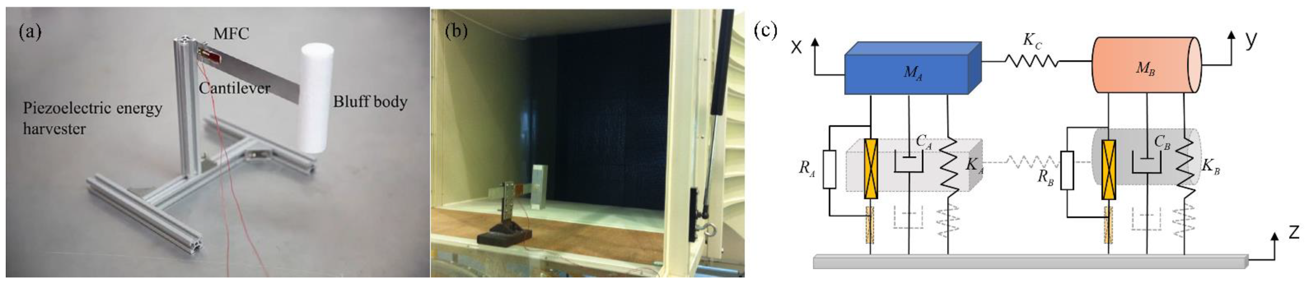
Conventionally, a cantilever beam attached with a cylinder bluff body forms a vortex-induced vibration piezoelectric energy harvester (VIVPEH), while a cantilever beam attached with a bluff body of a square section makes up a galloping piezoelectric energy harvester (GPEH). In this paper, we propose to couple the two typical wind energy harvesters and attempt to enlarge the effective working wind speed bandwidth. The voltage outputs are generated by piezoelectric patches installed on the cantilever beams. Each piezoelectric path has its own independent circuit. For convenience, the cantilever beam attached with a bluff body of square section is referred to as “beam A”, and the cantilever beam attached with the cylinder bluff body is referred to as “beam B”. Figure 1a displays the physical prototype of a conventional VIVPEH designed by Wang et al. [5]. Figure 1b shows the fabricated prototype of a conventional GPEH proposed by Tang et al. [19]. Since a cantilever beam energy harvester can usually be represented as an SDOF system, the proposed HWPEH can thus be described as a 2DOF system, as shown in Figure 1c, by adopting the lumped parameter representation method. The piezoelectric patch bonded on beam A is different from that of beam B. RA and RB are the load resistances connected to the two piezoelectric patches. By adjusting the spring stiffness, the GPEH and the VIVPEH can interact with each other. M, K, and C are the effective mass, stiffness, and damping coefficient, respectively. The subscripts A and B denote the GPEH and the VIVPEH. KC means the stiffness of the string. X and Y denote the vertical displacements of the GPEH and the VIVPEH, respectively. Additionally, Z represents the base displacement.
The displacements of the cylinder and square-sectioned bluff bodies are denoted by X and Y, respectively. The coupling spring connects the two bluff bodies. The coupling strength can be adjusted by changing the spring stiffness. The length of the square-sectioned bluff body is LA = 150 mm, and the dimensions of the cross section are 40 mm × 40 mm. The cylinder bluff body has a length of LB = 120 mm, and the diameter DB is 35 mm.
2.1. The GPEH Model
The bluff body at the end of the galloping beam vibrates under the action of the wind load, and the governing equation is as follows:
where MA is the equivalent mass that includes the contributions of the beam and the bluff body; CA is the damping coefficient; KA is the equivalent stiffness of the beam; is the displacement of the bluff body; and FA(t) is the aerodynamic force. FA(t) can be expressed as:
where ρa is the air density; U is the wind velocity; is the windward area of the bluff body and is the total aerodynamic force coefficient. is a function of the attack angle α, and can be determined through experiments or CFD (Computational Fluid Dynamics) simulations. For simplicity, can be empirically expressed as a polynomial expansion:
where are the empirical coefficients for the polynomial fitting. Therefore, the dynamic term can be expressed as follows:
By substituting Equation (4) into Equation (1), the governing equation can be transformed into the following form:
Galloping is caused by the instability of the fluid profile due to its own shape, which leads to vortex shedding at the wake of the bluff body and instability caused by other types of the cross flow. The cantilever beam in the wake acts as a separation plate and interferes with the regular vortex shedding [20]. This further enables the GPEH to quickly suppress VPEH shedding excitation. Therefore, this work ignores the effect of vortex shedding on GPEH dynamics and adopts 1-DOF lumped parameter model.
The vibration of the bluff body will result in the deformation of the cantilever beam, which will affect the electrical energy output of the piezoelectric sheet and convert the kinetic energy of the vibration into electric energy. Therefore, the electrical formula needs to be added to the governing equation.
It can be converted it into the state-space form:
2.2. The VIVPEH Model
VIV is induced by alternate shedding vortices downstream of a bluff body [21]. When the fluid flows around the bluff body, the wake behind the bluff body will periodically produce eddy currents. Vortex shedding will produce an asymmetric pressure field around the bluff body, which will be subjected to alternating aerodynamic forces, resulting in finite amplitude vibration. Facchinetti. et al. [22] pointed out that the wake oscillator model can be applied to describe vortex-induced vibration.
Beam B undergoes VIV, based on Euler’s beam theory and considering only the fundamental mode, the dynamic behavior of the cantilever subjected to the aerodynamic force is governed by the following equation:
where y(t) is the vibration displacement; is the equivalent mass of the bluff body; is the equivalent damping coefficient; is the equivalent stiffness of the system; is the aerodynamic force induced by vortex, which can be expressed as:
where represents the fluctuating lift coefficient; is the mean drag coefficient; and mean the bluff body’s diameter and length, respectively. Thus, Equation (8) is rewritten as:
Considering the wake behavior around the bluff body, the variable q(t) is introduced based on wake oscillator model.. The governing equation of q(t) can thus be expressed as:
where and A are equal to 0.3 and 12, determined experimentally. Additionally, the vortex shedding frequency:
By taking account of the shunt circuit, the governing equations of the VIVPEH can be written as:
The state-space form governing equations can be expressed as:
where ,
2.3. The HWPEH Model
In this paper, the two typical wind energy harvesters are proposed to be connected by a spring of stiffness KC. The coupled system is referred to as the hybrid wind piezoelectric energy harvester (HWPEH). Based on the governing equations of the GPEH and the VIVPEH and considering the existence of the coupling spring, the governing equations of the HWPEH can be expressed as:
Converting the above equation into the state-space form gives:
The parameters of the HWPEH to be investigated in this paper are listed in Table 1.
3. Parametric Studies
This section presents parametric studies to unveil the influence of different system parameters on the voltage output response of the HWPEH. Since the HWPEH comprises a GPEH and a VIVPEH, the two components are still referred to as the GPEH and the VIVPEH, though their aerodynamics should differ from their original ones when working independently.
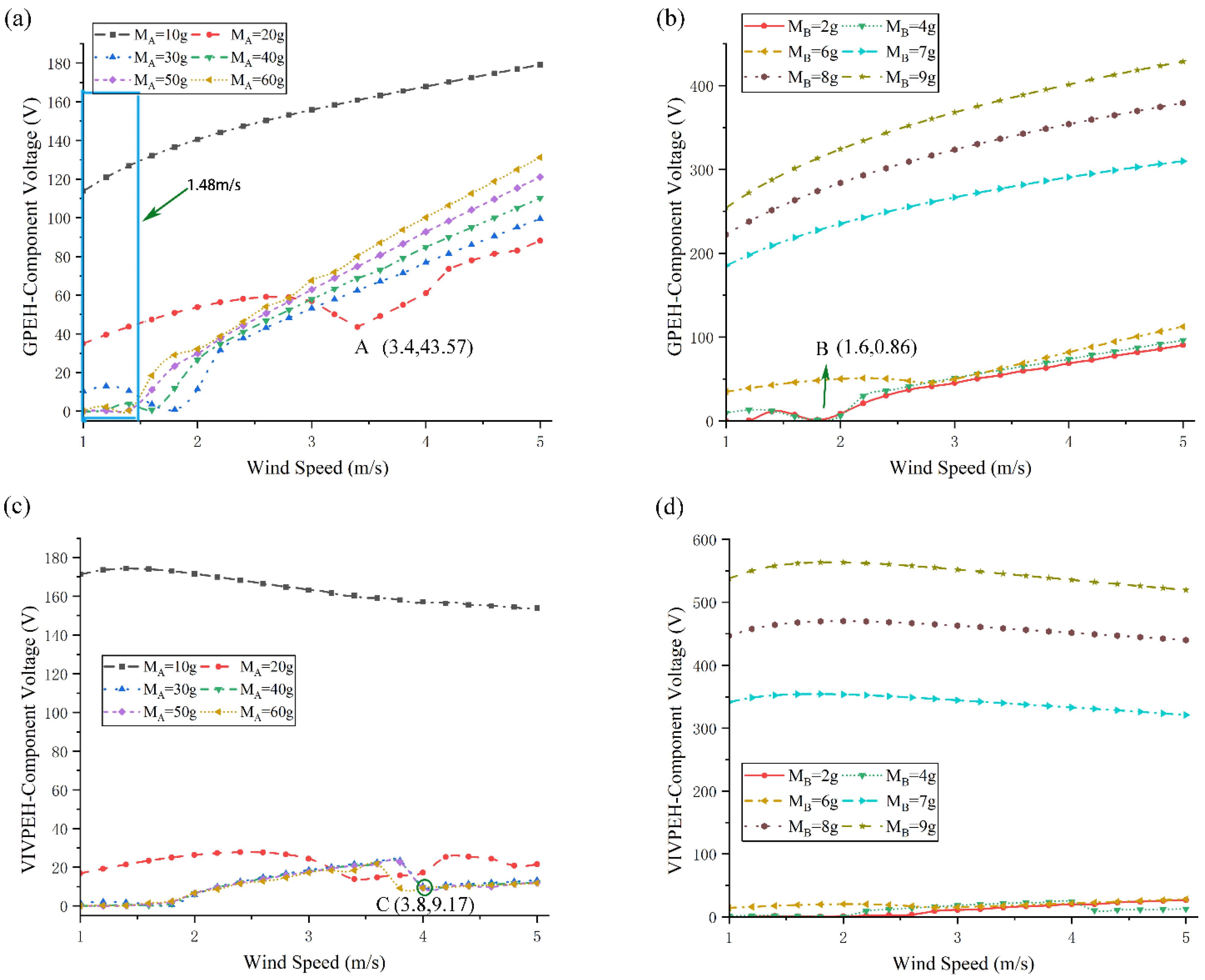
3.1. Effect of Mass
Figure 2a shows the change in the voltage output response of the GPEH-Component by varying MA, which is the mass of the square-sectioned bluff body. With the increase in MA, the output of the GPEH first decreases and then increases. At low wind speeds, as shown in the blue box in the figure, the output voltage at MA = 10 g, MA = 20 g, and MA = 30 g is considerably large. When MA is 20 g, there is an obvious drop point at point A, after which the voltage output rises steadily again. Figure 2b shows the change in the voltage output response of the GPEH-Component by varying MB, which is the mass of the cylinder bluff body. With the increase in MB, the voltage output from the GPEH-Component decreases. Similar to the phenomenon in Figure 2a, when MB is 2 g, the output voltage from the GPEH-Component has an obvious drop at point B. Figure 2c demonstrates how the voltage output response of the VIVPEH-Component varies with the change in MA. In the case of MA = 10 g, the output from the VIVPEH-Component is significantly large. When MA exceeds 20 g, the voltage output becomes remarkably smaller. For the three four cases, i.e., MA = 30, 40, and 50 g, the output of the VIVPEH-Component is almost unchanged and tends to be stable. When MA is 60 g, the locking interval of VIV is slightly changed. At point C, it drops in advance and tends to be stable. Figure 2d reveals the variation of the voltage output from the VIVPEH-Component in response to the change in MB. When MB is small, the output voltage is small, but when MB is increased to 7, 8, and 9 g, the output voltage increases remarkably.
3.2. Effect of Stiffness
Figure 3 presents the voltage output curves of the HWPEH as functions of the stiffnesses. Figure 3a shows the voltage outputs from the GPEH-Component for different KA. The whole wind speed range can be divided into three regions. In region I, when KA = 80 N/m, the GPEH voltage is approximately 90V, while when KA = 10 N/m, there is almost no output voltage. With the increase in output voltage, the cut-in wind speed decreases significantly. In region II, as the stiffness increases, the slope of the curve decreases. For example, the curve corresponding to KA = 10 N/m has a larger output slope, and the output voltage increases rapidly with the wind speed. Within region II, the voltage output may not monotonically increase with the wind speed, such as in the case of KA = 70 N/m. Region III corresponds to the high wind speed range. Over this wind speed range, the voltage output steadily increases with the increase in the wind speed. Figure 3b shows the voltage outputs from the GPEH-Component for different KB. It can be seen in Figure 3b that increasing KB will raise the cut-in wind speed and reduces the output voltage. Figure 3c depicts the influence of KA on the VIVPEH output. The output voltage increases drastically when KA is tuned to 80 N/m. In other cases, the changes are small. The curves for the cases of 70 and 80 N/m exhibit slight drop points at wind speeds between 3 and 4 m/s, respectively. In Figure 3d, with the increase in KB, the cut-in wind speed increases obviously, and its locking interval is shortened first and then widened.
3.3. Effect of Damping Coefficient
By changing the wind speed, Figure 4 demonstrates the variations of the HWPEH voltage output in response to different damping coefficients. Figure 4a,c illustrate the effects of CA on the GPEH- and VIVPEH-Components. As CA increases, the voltage outputs of both components decrease. When the damping coefficient is larger, for example, CA = 0.02 N/(m/s), the cut-in wind speed will increase to a certain level. As shown in Figure 4b, the influence of CB on the GPEH output voltage is mainly reflected in the cut-in wind speed. With the increase in CB, the cut-in wind speed of the GPEH-Component decreases obviously, but the output voltage becomes higher at low wind speeds. In Figure 4d, when CB increases, the output voltage from the VIVPEH decreases, the cut-in wind speed increases, and the locking interval shrinks.
3.4. Discussion on the Parametric Studies
Figure 5 presents the phase diagram of the bluff body velocity relative to the voltage output when the wind speed is 3 m/s. The trajectory starts at the center of the HWPEH and gradually spirals into the dark outer ring, indicating a limit cycle. As time approaches infinity, the trajectory spirals into to this limit cycle, suggesting the limit cycle is stable. In addition, due to the coupling effect of the two structures, it takes a longer time for the two components of the HWPEH to reach the stable limit-cycle oscillation, the trajectory patterns in Figure 5b,d are dense.
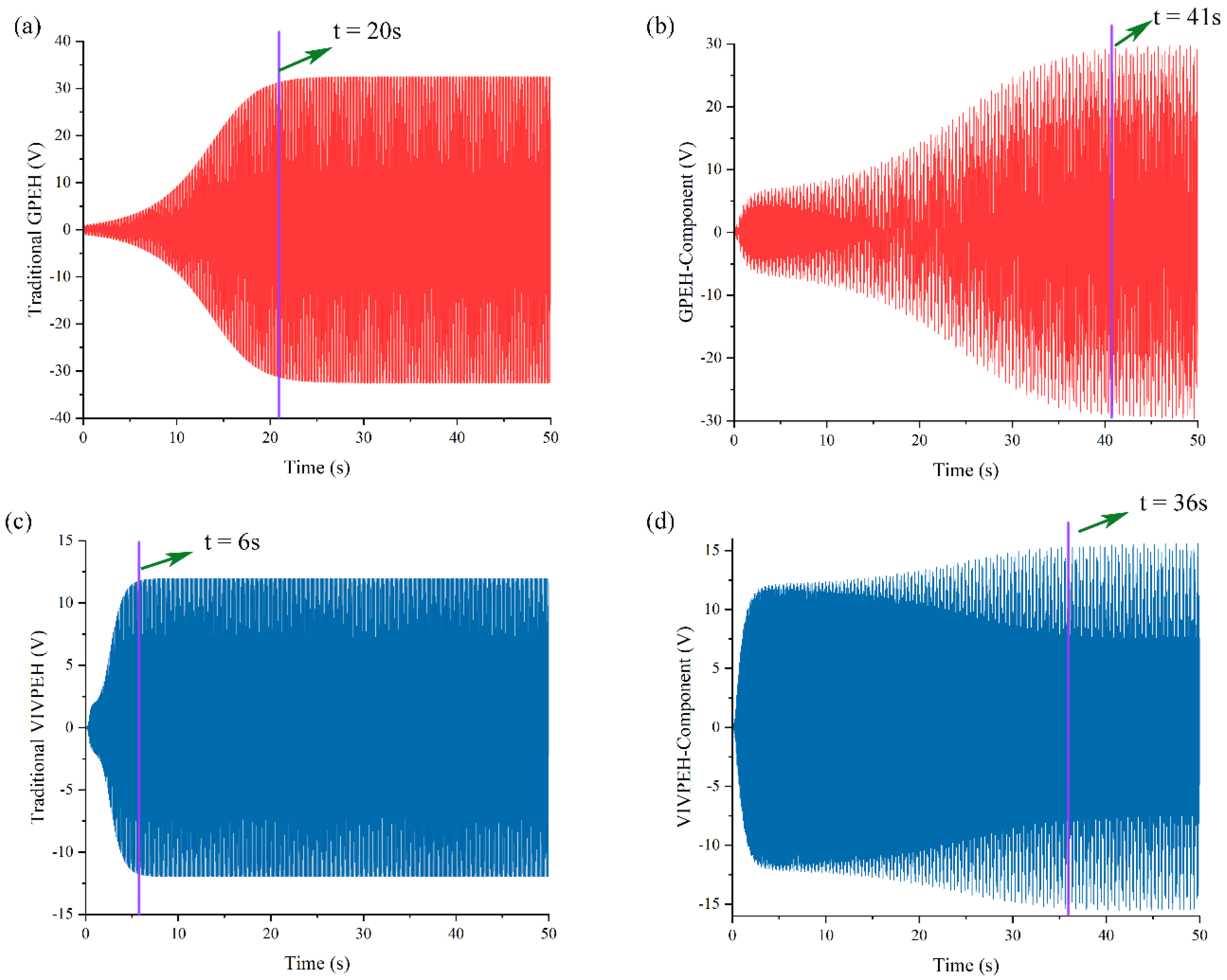
Figure 6 illustrates the time-domain waveforms of the harvester. Compared with the traditional harvesters, it took a longer time for the two components of the HWPEH to reach steady state. This result agrees with the deduction based on the phase plot in Figure 5. The traditional GPEH achieves its stable output when t = 20 s, while the GPEH-Component starts to produce a constant output until t = 41 s. Similarly, it takes 6 s for the traditional VIVPEH and 36 s for VIVPEH-Component to reach their steady state.
Figure 7 presents the Fast Fourier transform (FFT) results of the steady-state responses of the traditional GPEH, VIVPEH, and the proposed HWPEH at a wind speed of 3 or 6 m/s. It can be found in the first column of Figure 7 that when U = 3 m/s, the voltage outputs from the two components of the HWPEH are larger than the outputs of the traditional GPEH and VIVPEH. Moreover, traditional GPEH and VIVPEH only have one frequency component, while the HWPEH responses contain two frequency components since the HWPEH a 2DOF system. However, when U is increased to 6 m/s, the situation changes as revealed in Figure 7b,d. The voltage outputs from the HWPEH become slightly smaller than the traditional GPEH and VIVPEH, which cannot take place at U = 6 m/s. The second resonant mode of the HWPEH is not activated since the FFT result contains only a single frequency component.
By tuning the system parameters, the proposed HWPEH may exhibit three types of dynamic characteristics. The first type is shown in Figure 8a,b, where the cut-in wind speed of the traditional VIVPEH is lower than that of the traditional GPEH. After the combination, the cut-in wind speed of the HWPEH is as low as that of the traditional VIVPEH. The voltage outputs of the two components of the HWPEH are larger than the traditional GPEH and VIVPEH. The second type is shown in Figure 8c,d. The cut-in wind speeds of the traditional VIVPEH and GPEH are approximately the same. After coupling them to form the HWPEH, a valley appears on the response curve of the GPEH-Component. At high wind speeds, the HWPEH outperforms both the traditional VIVPEH and GPEH. Figure 8e,f present the third type response. The cut-in wind speed of the traditional VIVPEH is larger than that of the traditional GPEH. In this case, the cut-in wind speed of the HWPEH is almost the same as that of the traditional GPEH. In terms of the voltage output, the GPEH-Component of the HWPEH produces slightly higher outputs than the traditional GPEH, except over a certain small range of low wind speeds. The VIVPEH-Component of the HWPEH outperforms the traditional VIVPEH significantly.
The influence of the connection spring stiffness (KC) on the HWPEH is shown in Figure 9. With the increase in KC, the cut-in wind speed of the GPEH-Component increases and tends to be stable. At high wind speeds, the vibration displacement of the GPEH-Component first rises and then stabilizes at approximately 50 mm. For the VIVPEH-Component, the displacement increases with the increase in KC, and the peak moves to the high wind speed direction. At the same time, the locking interval is significantly widened. As shown by the arrow in the figure, when the spring stiffness is 27 N/m, the displacements of both components suddenly drop.
4. Impedance Matching Analysis
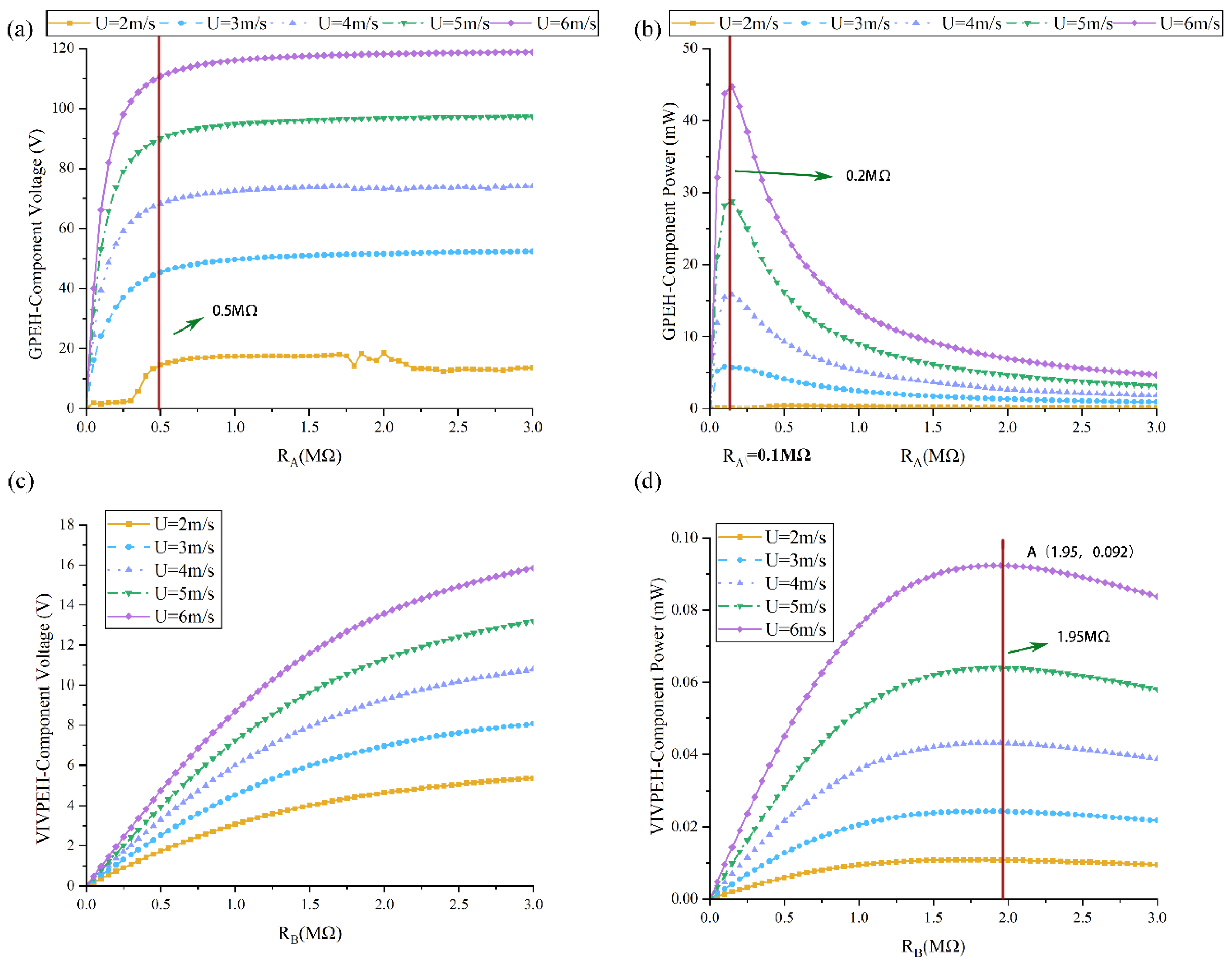
To study the influence of the resistive load on the performance of the energy harvester, the power, which is defined by the below formula, is evaluated:
Figure 10 depicts the effects of the resistive load on the HWPEH. Figure 10a shows that the output voltage of the GPEH-Component first increases and then tends to saturate as RA keeps increasing. Figure 10b illustrates that with the increase in RA, the power of the GPEH-Component first increases and then decreases, and the peak is attained at approximately RA = 0.2 MΩ, which is the optimal resistance. From Figure 10c, it is noted that the output voltage of the VIVPEH-Component increases monotonically with the increase in its shunt resistance RB, which is similar to the phenomenon in Figure 10a. However, Figure 10d shows that under the same wind speed, the power output produced by the VIVPEH-Component first increases and then decreases. It can be identified that the optimal resistive load of the VIVPEH-Component is approximately 1.95 MΩ.
5. Conclusions
In this paper, we have proposed a hybrid wind energy harvester that is realized by mechanically coupling a traditional GPEH and a traditional VIVPEH. This harvester has a low cut-in wind speed as with the traditional VIVPEH and a broad power generation bandwidth as with the traditional GPEH. We have analyzed the dynamics and the power generation performance of the HWPEH numerically. Additionally, the influences of mechanical parameters on the proposed HWPEH have been analyzed. The masses have a great influence on the voltage and cut-in wind speed. The stiffness affect the voltage rise slope and the working bandwidth of VPEH. The influences of damping coefficient are mainly reflected in the change in the cut-in wind speed. In terms of electrical parameters, increasing the resistive loads increases the voltage outputs of both components of the HWPEH. However, peaks are attained on the power curves when the shunt loads are tuned to the optimal resistances. In general, if the system parameters are well tuned, the bandwidth of the VIVPEH-Component increases significantly, and the cut-wind speed of both the GPEH- and VIVPEH-Components can be reduced.
Author Contributions
Conceptualization, Z.L. and B.Z.; methodology, B.Z. and K.L.; formal analysis, Z.L. and Y.Y.; validation, B.Z. and C.Z.; writing—review and editing, C.Z. and G.Z. All authors have read and agreed to the published version of the manuscript.
Funding
This work was financially supported by the State Key Laboratory of Structural Analysis for Industrial Equipment, Dalian University of Technology, China (GZ21114); the National Natural Science Foundation of China (Grant No. 52071059, 52192692, 52061135107); and The Fundamental Research Funds for the Central Universities (No: DUT20TD108).
Institutional Review Board Statement
Not applicable.
Informed Consent Statement
Not applicable.
Data Availability Statement
Data is contained within the article.
Conflicts of Interest
The authors declare no conflict of interest.
References
- Hu, G.; Tang, L.; Das, R.; Marzocca, P. A two-degree-of-freedom piezoelectric energy harvester with stoppers for achieving enhanced performance. Int. J. Mech. Sci. 2018, 149, 500–507. [Google Scholar] [CrossRef]
- Wang, J.; Yurchenko, D.; Hu, G.; Zhao, L.; Tang, L.; Yang, Y. Perspectives in flow-induced vibration energy harvesting. Appl. Phys. Lett. 2021, 119, 100502. [Google Scholar] [CrossRef]
- Wang, J.; Sun, S.; Tang, L.; Hu, G.; Liang, J. On the use of metasurface for Vortex-Induced vibration suppression or energy harvesting. Energy Convers. Manag. 2021, 235, 113991. [Google Scholar] [CrossRef]
- Kim, H.; Lee, J.; Seok, J. Novel piezoelectric wind energy harvester based on coupled galloping phenomena with characterization and quantification of its dynamic behavior. Energy Convers. Manag. 2022, 266, 115849. [Google Scholar] [CrossRef]
- Wang, J.; Tang, L.; Zhao, L.; Hu, G.; Song, R.; Xu, K. Equivalent circuit representation of a vortex-induced vibration-based energy harvester using a semi-empirical lumped parameter approach. Int. J. Energy Res. 2020, 44, 4516–4528. [Google Scholar] [CrossRef]
- Dai, H.L.; Abdelkefi, A.; Wang, L. Piezoelectric energy harvesting from concurrent vortex-induced vibrations and base excitations. Nonlinear Dyn. 2014, 77, 967–981. [Google Scholar] [CrossRef]
- Dai, H.L.; Abdelkefi, A.; Yang, Y.; Wang, L. Orientation of bluff body for designing efficient energy harvesters from vortex-induced vibrations. Appl. Phys. Lett. 2016, 108, 053902. [Google Scholar] [CrossRef]
- Wang, J.; Hu, G.; Su, Z.; Li, G.; Zhao, W.; Tang, L.; Zhao, L. A cross-coupled dual-beam for multi-directional energy harvesting from vortex induced vibrations. Smart Mater. Struct. 2019, 28, 12LT02. [Google Scholar] [CrossRef]
- Hu, G.; Liang, J.; Tang, L.; Wang, J. Improved theoretical analysis and design guidelines of a two-degree-of-freedom galloping piezoelectric energy harvester. J. Intell. Mater. Syst. Struct. 2021, 33, 210–230. [Google Scholar] [CrossRef]
- Wang, J.; Geng, L.; Ding, L.; Zhu, H.; Yurchenko, D. The state-of-the-art review on energy harvesting from flow-induced vibrations. Appl. Energy 2020, 267, 114902. [Google Scholar] [CrossRef]
- Azadeh-Ranjbar, V.; Elvin, N.; Andreopoulos, Y. Vortex-induced vibration of finite-length circular cylinders with spanwise free-ends: Broadening the lock-in envelope. Phys. Fluids 2018, 30, 105104. [Google Scholar] [CrossRef]
- Javed, U.; Abdelkefi, A. Impacts of the aerodynamic force representation on the stability and performance of a galloping-based energy harvester. J. Sound Vib. 2017, 400, 213–226. [Google Scholar] [CrossRef]
- Lan, C.; Tang, L.; Qin, W.; Xiong, L. Magnetically coupled dual-beam energy harvester: Benefit and trade-off. J. Intell. Mater. Syst. Struct. 2017, 29, 1216–1235. [Google Scholar] [CrossRef]
- Wang, J.; Geng, L.; Yang, K.; Zhao, L.; Wang, F.; Yurchenko, D. Dynamics of the double-beam piezo–magneto–elastic nonlinear wind energy harvester exhibiting galloping-based vibration. Nonlinear Dyn. 2020, 100, 1963–1983. [Google Scholar] [CrossRef]
- Wang, J.; Gu, S.; Zhang, C.; Hu, G.; Chen, G.; Yang, K.; Li, H.; Lai, Y.; Litak, G.; Yurchenko, D. Hybrid wind energy scavenging by coupling vortex-induced vibrations and galloping. Energy Convers. Manag. 2020, 213, 112835. [Google Scholar] [CrossRef]
- Hu, G.; Lan, C.; Liang, J.; Tang, L.; Zhao, L. Theoretical Study of a Two-Degree-of-Freedom Piezoelectric Energy Harvester under Concurrent Aeroelastic and Base Excitation. J. Intell. Mater. Syst. Struct. 2022, 33, 2000–2016. [Google Scholar] [CrossRef]
- Hu, G.; Wang, J.; Tang, L. A comb-like beam based piezoelectric system for galloping energy harvesting. Mech. Syst. Signal Process. 2020, 150, 107301. [Google Scholar] [CrossRef]
- Hu, G.; Wang, J.; Qiao, H.; Zhao, L.; Li, Z.; Tang, L. An experimental study of a two-degree-of-freedom galloping energy harvester. Int. J. Energy Res. 2020, 45, 3365–3374. [Google Scholar] [CrossRef]
- Tang, L.; Zhao, L.; Yang, Y.; Lefeuvre, E. Equivalent Circuit Representation and Analysis of Galloping-Based Wind Energy Harvesting. IEEE/ASME Trans. Mechatron. 2014, 20, 834–844. [Google Scholar] [CrossRef]
- Yang, Y.; Zhao, L.; Tang, L. Comparative study of tip cross-sections for efficient galloping energy harvesting. Appl. Phys. Lett. 2013, 102, 064105. [Google Scholar] [CrossRef]
- Bashir, M.; Rajendran, P.; Khan, S.A. Energy Harvesting from Aerodynamic Instabilities: Current prospect and Future Trends. IOP Conf. Ser. Mater. Sci. Eng. 2018, 290, 012054. [Google Scholar] [CrossRef]
- Facchinetti, M.; de Langre, E.; Biolley, F. Coupling of structure and wake oscillators in vortex-induced vibrations. J. Fluids Struct. 2004, 19, 123–140. [Google Scholar] [CrossRef]
Figure 1.
(a) Physical prototype of a conventional VIVPEH [5]; (b) physical prototype of a conventional GPEH [19]; (c) lumped parameter representation of the 2DOF HWPEH.

Figure 2.
Effects of masses on the voltage of the HWPEH (KA = 52.01 N/m; KB = 9.894 N/m; CA = 0.0121 N/(m/s); CA = 0.0121 N/(m/s); KC = 5 N/m): (a) MA on GPEH; (b) MB on GPEH; (c) MA on VIVPEH; (d) MB on VIVPEH.
Figure 2.
Effects of masses on the voltage of the HWPEH (KA = 52.01 N/m; KB = 9.894 N/m; CA = 0.0121 N/(m/s); CA = 0.0121 N/(m/s); KC = 5 N/m): (a) MA on GPEH; (b) MB on GPEH; (c) MA on VIVPEH; (d) MB on VIVPEH.

Figure 3.
Effects of stiffness on the voltage of the HWPEH (MA = 28.16 g; MB = 4.316 g; CA = 0.0121 N/(m/s); CA = 0.0121 N/(m/s); KC = 5 N/m): (a) KA on GPEH; (b) KB on GPEH; (c) KA on VIVPEH; (d) KB on VIVPEH.
Figure 3.
Effects of stiffness on the voltage of the HWPEH (MA = 28.16 g; MB = 4.316 g; CA = 0.0121 N/(m/s); CA = 0.0121 N/(m/s); KC = 5 N/m): (a) KA on GPEH; (b) KB on GPEH; (c) KA on VIVPEH; (d) KB on VIVPEH.

Figure 4.
Effects of damping coefficient on the voltage of the HWPEH (MA = 28.16 g; MB = 4.316 g; KA = 52.01 N/m; KB = 9.894 N/m; KC = 5 N/m): (a) CA on GPEH; (b) CB on GPEH; (c) CA on VIVPEH; (d) CB on VIVPEH.
Figure 4.
Effects of damping coefficient on the voltage of the HWPEH (MA = 28.16 g; MB = 4.316 g; KA = 52.01 N/m; KB = 9.894 N/m; KC = 5 N/m): (a) CA on GPEH; (b) CB on GPEH; (c) CA on VIVPEH; (d) CB on VIVPEH.

Figure 5.
Phase portrait (U = 3 m/s): (a) traditional GPEH; (b) GPEH-Component of the HWPEH; (c) traditional VIVPEH; (d) VIVPEH-Component of the HWPEH.
Figure 5.
Phase portrait (U = 3 m/s): (a) traditional GPEH; (b) GPEH-Component of the HWPEH; (c) traditional VIVPEH; (d) VIVPEH-Component of the HWPEH.

Figure 6.
The time-domain waveforms of the harvester (U = 3 m/s): (a) traditional GPEH; (b) GPEH-Component of the HWPEH; (c) traditional VIVPEH; (d) VIVPEH-Component of the HWPEH.
Figure 6.
The time-domain waveforms of the harvester (U = 3 m/s): (a) traditional GPEH; (b) GPEH-Component of the HWPEH; (c) traditional VIVPEH; (d) VIVPEH-Component of the HWPEH.

Figure 7.
Fast Fourier transform (FFT) of the steady-state response: (a) traditional GPEH versus GPEH-Component of the HWPEH at U = 3 m/s; (b) traditional GPEH versus GPEH-Component of the HWPEH at U = 6 m/s; (c) traditional VIVPEH versus VIVPEH-Component of the HWPEH at U = 3 m/s; (d) traditional VIVPEH versus VIVPEH-Component of the HWPEH at U = 6 m/s.

Figure 8.
The displacement of three HWPEH conditions: (a) traditional GPEH versus GPEH-Component of the HWPEH when the cut-in wind speed of traditional VPEH is lower than that of the traditional GPEH. (b) Traditional VPEH versus VIVPEH-Component of the HWPEH when the cut-in wind speed of traditional VPEH is lower than that of the traditional GPEH. (c) Traditional GPEH versus GPEH-Component of the HWPEH when the cut-in wind speed of traditional VPEH and traditional GPEH are approximately the same. (d) Traditional VPEH versus VPEH-Component of the HWPEH when the cut-in wind speed of traditional VPEH and traditional GPEH are approximately the same. (e) Traditional GPEH versus GPEH-Component of the HWPEH when the cut-in wind speed of traditional VPEH is higher than that of the traditional GPEH. (f) Traditional VPEH versus VPEH-Component of the HWPEH when the cut-in wind speed of traditional VPEH is higher than that of the traditional GPEH.

Figure 9.
Effects of KC on HWPEH: (a) GPEH-Component displacement; (b) VIVPEH-Component displacement.
Figure 9.
Effects of KC on HWPEH: (a) GPEH-Component displacement; (b) VIVPEH-Component displacement.

Figure 10.
Effects of the resistive load on the output of the HWPEH under different wind speeds: (a) RA on GPEH voltage; (b) RA on GPEH average power; (c) RB on VPEH voltage; (d) RB on VPEH average power.
Figure 10.
Effects of the resistive load on the output of the HWPEH under different wind speeds: (a) RA on GPEH voltage; (b) RA on GPEH average power; (c) RB on VPEH voltage; (d) RB on VPEH average power.


Table 1.
System parameters of the HWPEH to be investigated.
| Mechanical Parameters | Aerodynamic Parameters | ||
|---|---|---|---|
| GPEH effective mass (g) | 28.16 | Air density, ρ (kg·m−3) | 1.204 |
| VIVPEH effective mass (g) | 4.316 | Empirical aerodynamic coefficients of polynomial expansion of | |
| GPEH effective stiffness (N·m−1) | 52.01 | ||
| VIVPEH effective stiffness (N·m−1) | 9.894 | ||
| GPEH effective damping | 0.019 | Amplitude of the fluctuating lift force coefficient | 0.490 |
| VIVPEH effective damping | 0.01 | ||
| GPEH electromechanical coupling (μN·V−1) | 370.6 | Mean drag coefficient | 1.331 |
| VIVPEH electromechanical coupling (μN·V−1) | 98.94 | Strouhal number | 0.128 |
| GPEH capacitance, (nF) | 180 | ||
| VIVPEH capacitance, (nF) | 12.2 | ||
| GPEH resistive load, (MΩ) | 3.5 | ||
| VIVPEH resistive load, (MΩ) | 3.5 | ||
Publisher’s Note: MDPI stays neutral with regard to jurisdictional claims in published maps and institutional affiliations. |
© 2022 by the authors. Licensee MDPI, Basel, Switzerland. This article is an open access article distributed under the terms and conditions of the Creative Commons Attribution (CC BY) license (https://creativecommons.org/licenses/by/4.0/).
Share and Cite
MDPI and ACS Style
Li, Z.; Liu, K.; Zhao, C.; Zhou, B.; Yang, Y.; Zhang, G. A Dual-Beam Coupled System for Hybrid Galloping and Vortex-Induced Vibration Energy Harvesting. Symmetry 2022, 14, 2601. https://0-doi-org.brum.beds.ac.uk/10.3390/sym14122601
AMA Style
Li Z, Liu K, Zhao C, Zhou B, Yang Y, Zhang G. A Dual-Beam Coupled System for Hybrid Galloping and Vortex-Induced Vibration Energy Harvesting. Symmetry. 2022; 14(12):2601. https://0-doi-org.brum.beds.ac.uk/10.3390/sym14122601
Chicago/Turabian StyleLi, Zhiqing, Kaihua Liu, Chaoyang Zhao, Bo Zhou, Yaowen Yang, and Guiyong Zhang. 2022. "A Dual-Beam Coupled System for Hybrid Galloping and Vortex-Induced Vibration Energy Harvesting" Symmetry 14, no. 12: 2601. https://0-doi-org.brum.beds.ac.uk/10.3390/sym14122601
Note that from the first issue of 2016, this journal uses article numbers instead of page numbers. See further details here.