1. Introduction
Metal forming processes for the manufacture of pipe-shaped parts require the generation of process models as an essential task of production engineering [
1]. In recent years, a great effort has been made in the technological development of this type of model, generating a wide variety that is continually expanding [
2]. The need to continually advance the modeling of processes and their limits is a recent trend in manufacturing engineering. Robust process design and parameterization can be effectively evaluated with appropriate models [
3], which helps feed the demand for tighter product tolerances [
4]. The inclusion of these models and the virtualization of the work area and workpiece allow the digitization of manufacturing in the era of new smart factories [
5]. The metal forming processes to be modeled are among the most relevant.
Among the parts that can be fabricated by sheet metal forming, many engineering applications, such as oil and gas framework platforms, tunnel construction, and commercial and industrial buildings [
6], employ medium and large-size tubes and tube sections. The round pipes generally have single or double-order bends. The manufacturing of the tubes can be done sequentially or divided into phases, first by pre-forming or roll bending, and then by forming to final geometry. Efficient bending is a prerequisite for the accurate formation of bending surfaces [
7]. In normal practice, the skill, knowledge and experience of the operator largely determine the final quality of roll bending. Process fine-tuning by trial and error and subsequent template work is a common practice in the industry.
However, in recent years, much work has been devoted to the modeling and simulation of the bending of sheet metal. Many publications exist on the fabrication and finite element simulation of roll bending [
8,
9,
10,
11,
12,
13]. However, it only applies to roll bending of open geometry workpieces of sizes less than 100 mm in any dimension; little is reported for oil and gas industry-oriented workpieces with dimensions greater than 1000 mm, such as petroleum gas pipes. As a result, the authors believe that it is worthwhile to study the roll bending of large pipes using a finite element model (FEM). For large pipes, validation of the FEM simulation is a big problem experimentally. To validate the geometrical deviation for large components, it will be more efficient to perform the symmetry assessment.
Additionally, given the vital significance of the bending process, it is quite unusual not to find extensive literature concerning the symmetry of the process in a practical way. This paper aims to fill this gap, as a novelty, through numerical analysis of the deformation of sheet metal. The implications on the symmetry of the final geometry are generated, and finally, it is compared experimentally.
2. Materials and Methods
To perform the simulation, the reference pipe component is shown in
Figure 1a. The forming process,
Figure 1b, consists of the selected stages of manufacturing of cans with the received base material (metal plates). This process is carried out with a three-roller bending machine and consists of performing several roll-bending sequences in an iterative process. It starts by inserting the end of the plate in the three-roller bending machine with the help of a gantry, ensuring that it is centred regarding the rollers. Then, pressure is applied with the upper roller over the plate that relies on two rollers to prevent the plate from coming loose. This operation is repeated until the curvature complies with the curvature tolerances, verified by the worker with a template.
In this paper, the three-roll forming process was investigated using finite element (FE) analysis. The software package used for this forming simulation is LS-DYNA. The dimensions of the pipe component are highlighted in
Table 1.
To manufacture the pipe component, the three-roller bending machine is used. The schematic diagram of the three-roller bending machine is given in
Figure 2. It essentially consists of a sheet metal, top roller, and lower rollers (front and rear). The position of the rollers is fixed as given in
Figure 2.
The diameters of each of the rollers are different, while the length of the lower rollers is L = 4167 mm, and the top roller has a length of L = 4610 mm. The maximum distance between the lower rollers and top roller is 100 mm, and this will be adjusted based on the thickness of the sheet metal. In operation, the sheet metal is fed into the rollers. Then, by changing the position of the rear roller, it is bent to a desired curve. After that, the front roller rotates to advance the sheet metal and continue its movement to form the desired shape of the curvature. However, the top roller and front roller do not exert pressure for bending. They are used as a support for the sheet metal; they simply rotate to allow the sheet metal to pass through. They exert no pressure. The process of three-roll bending is highly dependent on the experience and expertise of the operator. Sheet metal bending is usually performed using the multiple-pass method, also known as “trial and error,” to maximize the bending ability of rollers. However, this can entail high costs due to material waste and increased production time during the multi-pass method. The process consistency, accuracy and efficiency demand the utilization of a minimum-pass approach in production. This method, however, has always been difficult because an operator must know the different machine configurations to obtain a pipe component with the required diameter.
From a finite element modeling perspective, the roll forming process is more difficult than the traditional forming process. The sheet is drawn into the rolling slot by friction caused by the movements of the lower rollers and top roller. In order to model the roll-bending process using the LS-DYNA finite element code and to guarantee the precision and effectiveness of the calculations, several key techniques were considered, such as geometry modeling, assembly, treatment of contact boundary conditions, material property definition, etc. These techniques are detailed in the following section.
2.1. Finite Element Model (FEM)
The FE model of the entire three-roll bending process consists of a sheet and rollers. The sheet material is assumed to be isotropic, and the material model is taken to be elastoplastic. The implicit/explicit time integrations are applied for the calculation, and the gravity effect of the metal plate was considered. However, during the simulation, the LS-DYNA algorithm understands the time integration and simulates the model accordingly. Here, the simulation of the given model is done by using the implicit method.
2.2. Materials
The rollers were manufactured in carbon steel and considered rigid bodies. Sheet metal with the dimensions 11,938 mm (length) × 4000 mm (width) × 22 mm (thickness) and made up of SA-516 Gr.70N was identified as a deformable part. The material properties of SA-516 Gr.70N are given in
Table 2. The uniaxial tensile test is performed to obtain the engineering stress-strain curve to define the plastic behavior of the material, as presented in
Figure 3.
The difficulty of the forming process requires the use of advanced simulation software. When selecting a material model for the sheet metal (among 100+ models currently given in LS-DYNA), several considerations should be addressed: (i) the model must be suitable for metals/nonmetals; (ii) the model must address plasticity; and (iii) the model must be capable of studying fracture. In accordance with the above statements, the piecewise linear plasticity material model was chosen for this paper.
The piecewise linear plasticity model is a material model which gives the hardening stress–strain curve as an input. Yield stress is given by
However, in this case, the process is not strain-rate dependent. Therefore, in the numerical algorithm, the plastic strain increment can be easily calculated by using the following equation.
All the parameters are obtained using the true stress-true strain curve using the uniaxial tensile test as shown in
Figure 3.
is the equivalent stress at an incremental plastic strain,
is the yield stress,
G is the shear modulus of the material (76.8 GPa), and
H is the strain hardening moduli, which can be evaluated by taking the slope where the stress–strain curve changes at the yield point. In the piecewise linear plasticity model, the failure criteria is used, where the equivalent plastic strain at failure and fracture stress value in the LS-DYNA material card is introduced. It is determined from the curve obtained from the uniaxial tensile test. However, this criterion is not very useful for this application as the main intent is to study the bend pipe’s roundness with minimum equivalent plastic strain. The parameters for material models are optimized based on the stress-strain curve obtained from the tensile testing and also compared with the tensile FEM simulation. Then, it is introduced to the actual simulation of the bending process.
2.3. Boundary Conditions (Constraints, Load, and Contacts Definition)
All loads and constraints were referenced to the global coordinate system and the local coordinate for the rear roller, as shown in
Figure 4. The model was performed in two stages. One was the bending of the sheet metal, or just “bending”. The second stage was the circumferential bending of the sheet, referred to as “rolling”. Prescribed movements of the rigid bodies of the rollers were shown by the center point of the roller. Thus, the constraints and loads were applied to the centers of the rollers. The boundary conditions are shown in
Figure 4. In the first stage, the top and front rollers were free to rotate at the global X-axis, while the rear roller was restricted to translating only along the Z’-axis of local coordinates at 60°. At the second stage, the front roller rotated. The speed provided by the front roller is 6.23 m/min (about ω = 2 rpm/min), while the top roller remained in the same state as defined in the earlier stage; after the rear roller is shifted, it is constrained to the z’-axis of local coordinate in the second stage.
The LS-DYNA FE code uses automatic surface-to-surface contact and interactions between different roll bending parts. A master/slave contact approach is used in the analysis, where the rollers are considered the master surfaces, and the sheet metal opposite surfaces of the rollers are the slaves. Coulomb’s friction law was used between the sheet and rollers. The dynamic and static friction coefficients were selected as 0.25 and 0.5, respectively. For meshing the model, solid elements are used. However, normally, shell elements are used for any forming simulation, but as we are going to perform the welding simulation after the roll-bending simulation in future studies, we chose the 3D solid elements. Several numbers of simulations were performed by varying the rear roller position in order to obtain the accurate curvature of the pipe component (final position was 183 mm towards the z’-axis). The overall CPU time was approximately 420 min for the model with more than 8898 elements. At the beginning of FEM simulation, the optimization of the numerical model in terms of a mesh sensitivity analysis is performed, where the effect of the number of meshes (mesh size) and the type of mesh on the bending of the sheet metal and its influence studied using the roundness error, effective stress—plastic strain and on relative CPU time is compared. The quad element is selected for this application, as it is normally used for sheet metal-forming FEM simulation and to reduce the computational time as compare to the tria element.
Table 3 compares the influence of different mesh sizes.
From the above
Table 3, it has been seen that the coarse mesh predicts less accurately in terms of average radius error, effective stress and strain, but the normal and fine meshes all predict similar results. However, in this FEM simulation, the normal mesh is used, which shows better-converged results and less CPU time compared to the fine mesh.
3. Results and Discussion
The FE model assembly is shown in
Figure 5, and the various steps of the roll bending process obtained by numerical calculation are shown in
Figure 6. It is clear that the curvature distribution was asymmetrical approximately at the rear roll contact point (between the rear roll and the sheet).
3.1. Residual Stress and Plastic Strain Distribution
Figure 7 and
Figure 8 show the distribution of residual stress and equivalent plastic strain generated during the forming process. The unit of measurement considered in this simulation is the GM unit (kg, mm, ms, KN, GPa, KN-mm). Therefore, the stress is expressed in GPa. The maximum stress obtained during the process was 0.837 GPa, and equivalent plastic strain was around 1.55% throughout the formed pipe.
To better understand the stress and plastic strain distribution behavior in the bent portion of the sheet metal, the following observations were made. It is observed that the maximum plastic strain was generated at the initial bending condition.
Figure 9 shows the distribution of the equivalent plastic strain over the sheet thickness. The peak plastic strain was found at the surface of the pipes, and the minimum value was found in the neutral zone of the fibers.
Figure 10 shows that the minimum residual stress was located near the neutral fiber of 0.040 GPa (40 MPa). Neutral fiber distance increased, while residual stress increased continuously until it reached a value of 0.1306 GPa (130.6 MPa) at the sheet surface.
3.2. Pipe Dimension Analysis
The final dimensions of the obtained pipe are analyzed as shown in
Figure 11, and it is found that the thickness of the sheet remained almost constant after the roll-bending processes.
The diameter of the pipe obtained was 3865.2 mm, very close to the target (3800 mm). The small diameter deviation is due to several factors, e.g., the initial position of the sheet on the lower roll and the fact that the end of the sheet is not bent and leaves a gap of 80 mm. This phenomenon needs to be analyzed further.
3.3. Modelling Validation (Roudness and Symmetry of Curvature Simulation vs. Real Data/Symmetry from Middle Plane)
To justify and validate the FEM model of the three-roller bending process, a structured light sensor (motionCam3D) is used to provide real-time measurement during the forming process in the form of a point cloud.
The aim of this system is to check the curvature of the can in the area near to the rollers, just as the operators do, as shown in
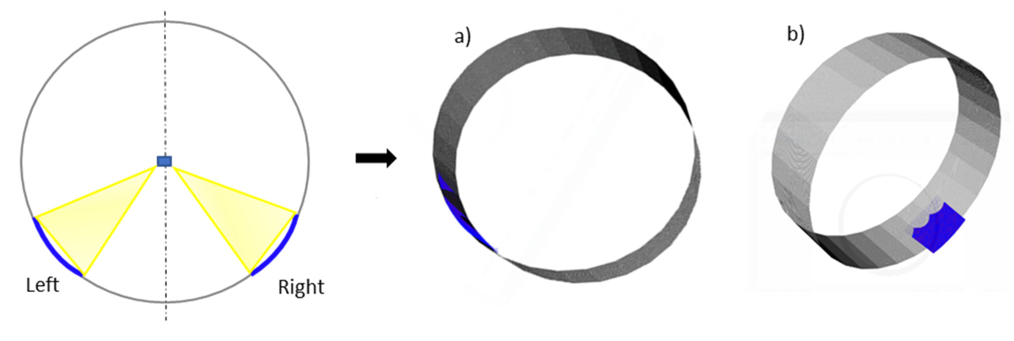
Figure 12. The light sensor is connected in such a way that it capture the points at beginning of pipe curvature and throughout the process. However, in order to validate in a more efficient way, the two different map of the point cloud are captured for the curvature of the pipe at the beginning (first pre-bending) and at the end of pipe forming (last) to compare the symmetrical deviation in curvature measurement. The curvature is computed by calculating the fitting cylinder (gray) of the section acquired by the sensor (blue) during the experiment, as shown in
Figure 13.
The accuracy of this measuring system is compared with the FEM simulation results and given in the following
Table 4. This table compares the least-squares best-fit arc radii with the desired radii. The final product from the experiment and the FEM simulation was noticeably coherent with the target shape, and the difference was not significant.
While the largest deviation between the formed pipes and the target shapes from the experiment and FEM was about approximately 2 mm, the shape error is acceptable because it is in the allowable range. At this level of shape error, no problems exist with the assembly process; moreover, the error can be reduced by gaining more numerical data. This technique helps us to validate the FEM simulation with the experimental results, as is normally done in the literature [
14].
4. Conclusions
A FEM simulation method has been developed using LS-DYNA for sheet metal forming with three rolls to produce large parts. The simulation is carried out on the real user case of a 4-m long tube with a nominal diameter of 3.8 m. Several simulation maps are then carried out to obtain the desired tube diameter with respect to the rear roller positions for a sheet thickness of 22 mm. Some of the conclusions drawn from this work are as follows:
This model makes it possible to predict dimensions of the tube with the input parameters of the three-roll bending process. In this paper, parameter selection is based on the technical data of the three-roll bending process currently used;
The residual stress and plastic deformation through the thickness of the plate are estimated, and the final dimensions of the tube are discussed. The minimum residual stress was in the vicinity of the neutral fiber (value 40 MPa), with a symmetrical distribution of the equivalent plastic strain and von Mises stress, with a maximum value of 130.6 MPa;
Finally, validation of the FEM simulation is carried out experimentally. This comparison showed that the numerical and experimental results agree, with a shape error of 1.95% in the experimental case and 2.3% for the simulation.
Author Contributions
Conceptualization, T.B., M.P. and F.V.; data curation, F.V., T.B. and A.C.; formal analysis, F.V., T.B. and A.C.; investigation, F.V., M.P. and A.C.; methodology, F.V. and A.C.; project administration, C.R.; supervision, M.P.; validation, T.B. and M.P.; writing—original draft, F.V. and T.B.; writing—review and editing, F.V., T.B., M.P. and A.C. All authors have read and agreed to the published version of the manuscript.
Funding
The authors acknowledge the funding from the European Union’s Horizon 2020 research and innovation programme under grant agreement No. 958303.
Institutional Review Board Statement
Not applicable.
Informed Consent Statement
Not applicable.
Data Availability Statement
Data available on request from the corresponding author.
Conflicts of Interest
The authors declare no conflict of interest.
References
- Tekkaya, A.E.; Allwood, J.M.; Bariani, P.F.; Bruschi, S.; Cao, J.; Gramlich, S.; Groche, P.; Hirt, G.; Ishikawa, T.; Lobbe, C.; et al. Metal forming beyond shaping: Predicting and setting product properties. CIRP Ann. 2015, 64, 629–653. [Google Scholar] [CrossRef]
- Volk, W.; Groche, P.; Brosius, A.; Ghiotti, A.; Kinsey, B.L.; Liewald, M.; Madej, L.; Min, J.; Yanagimoto, J. Models and modelling for process limits in metal forming. CIRP Ann. 2019, 68, 775–798. [Google Scholar] [CrossRef]
- Wang, B.; Tao, F.; Fang, X.; Liu, C.; Liu, Y.; Freiheit, T. Smart manufacturing and intelligent manufacturing: A comparative review. Engineering 2021, 7, 738–757. [Google Scholar] [CrossRef]
- Starman, B.; Cafuta, G.; Mole, N. A Method for Simultaneous Optimization of Blank Shape and Forming Tool Geometry in Sheet Metal Forming Simulations. Metals 2021, 11, 544. [Google Scholar] [CrossRef]
- Ralph, B.; Stockinger, M. Digitalization and digital transformation in metal forming: Key technologies, challenges and current developments of industry 4.0 applications. In XXXIX Colloquium on Metal Forming 2020; Montanuniversität Leoben, Lehrstuhl für Umformtechnik: Leoben, Austria, 2020; pp. 13–23. [Google Scholar]
- Hua, M.; Baines, K.; Cole, I.M. Continuous four-roll plate bending: A production process for the manufacture of single seamed tubes of large and medium diameters. Int. J. Mach. Tools Manuf. 1999, 36, 905–935. [Google Scholar] [CrossRef]
- Batalov, G.S.; Lunev, A.A.; Radionova, L.V.; Lezin, V.D. Development of New Methods for the Production of Large-Diameter Double-Seam Pipes. In Solid State Phenomena; Trans Tech Publications Ltd.: Bäch, Switzerland, 2021; Volume 316, pp. 538–548. [Google Scholar]
- Paralikas, J.; Salonitis, K.; Chryssolouris, G. Investigation of the effect of roll forming pass design on main redundant deformations on profiles from AHSS. Int. J. Adv. Manuf. Technol. 2011, 56, 475–491. [Google Scholar] [CrossRef]
- Yang, M.; Shima, S. Simulation of pyramid type three-roll bending process. Int. J. Mech. Sci. 1988, 30, 877–886. [Google Scholar] [CrossRef]
- Fan, S.T.; Meng, S.F. Simulation of the three-roll pyramid type plate bending machine: Multi-bending process. Mach. Des. Manuf. 2007, 6, 82–84. [Google Scholar]
- Feng, Z.; Champliaud, H. Modeling and simulation of asymmetrical three-roll bending process. Simul. Model. Pract. Theory 2011, 19, 1913–1917. [Google Scholar] [CrossRef]
- Shin, J.G.; Park, T.J.; Yim, H. Kinematics based determination of the rolling region in roll bending for smoothly curved plates. J. Manuf. Sci. Eng. 2001, 123, 284–290. [Google Scholar] [CrossRef]
- Gandhi, A.H.; Raval, H.K. Analytical and Empirical Modeling of Top Roller Position for Three-Roller Cylindrical Bending of Plates and Its Experimental Verification. J. Mater. Process. Technol. 2008, 197, 268–278. [Google Scholar] [CrossRef]
- Urbikain, G.; Alvarez, A.; López de Lacalle, L.N.; Arsuaga, M.; Alonso, M.A.; Veiga, F. A Reliable Turning Process by the Early Use of a Deep Simulation Model at Several Manufacturing Stages. Machines 2017, 5, 15. [Google Scholar] [CrossRef]
Figure 1.
Real case scenario: (a) reference can used in a pipeline and (b) the forming process.
Figure 1.
Real case scenario: (a) reference can used in a pipeline and (b) the forming process.
Figure 2.
Configuration of the three-roller bending machine and its working principle.
Figure 2.
Configuration of the three-roller bending machine and its working principle.
Figure 3.
Stress–plastic strain curve of SA-516 Gr.70N sheet metal plate.
Figure 3.
Stress–plastic strain curve of SA-516 Gr.70N sheet metal plate.
Figure 4.
Boundary conditions.
Figure 4.
Boundary conditions.
Figure 5.
FE model assembly.
Figure 5.
FE model assembly.
Figure 6.
Roll-bending process at different steps: (a) initial bending position; (b) initial roll-bending; (c) 25% of the roll-bending process; (d) 50% of the roll-bending process; (e) 75% of the roll-bending process; (f) obtained pipe.
Figure 6.
Roll-bending process at different steps: (a) initial bending position; (b) initial roll-bending; (c) 25% of the roll-bending process; (d) 50% of the roll-bending process; (e) 75% of the roll-bending process; (f) obtained pipe.
Figure 7.
Residual stress formation during the pipe-forming process.
Figure 7.
Residual stress formation during the pipe-forming process.
Figure 8.
Distribution of equivalent plastic strain.
Figure 8.
Distribution of equivalent plastic strain.
Figure 9.
(a) Distribution of equivalent plastic strain along the sheet thickness which is bent. (b) Corresponding graph along the sheet thickness from node 59079 to 78945.
Figure 9.
(a) Distribution of equivalent plastic strain along the sheet thickness which is bent. (b) Corresponding graph along the sheet thickness from node 59079 to 78945.
Figure 10.
(a) Distribution of equivalent von Mises stress over a section of bend along the sheet thickness. (b) Corresponding graph along the sheet thickness from node 59079 to 78945.
Figure 10.
(a) Distribution of equivalent von Mises stress over a section of bend along the sheet thickness. (b) Corresponding graph along the sheet thickness from node 59079 to 78945.
Figure 11.
Dimension of the final obtained pipe after simulation compared with targeted shape.
Figure 11.
Dimension of the final obtained pipe after simulation compared with targeted shape.
Figure 12.
Measuring technqiue used to measure the curvature of the pipe.
Figure 12.
Measuring technqiue used to measure the curvature of the pipe.
Figure 13.
Curvature of the pipe obtained from the sensor, on left denoted by (a) after first pre-bending and right give by (b) at the end of the bending process.
Figure 13.
Curvature of the pipe obtained from the sensor, on left denoted by (a) after first pre-bending and right give by (b) at the end of the bending process.
Table 1.
Dimensions of the pipe component.
Table 1.
Dimensions of the pipe component.
| Diameter | 3800 mm |
| Length | 4000 mm |
| Thickness | 22 mm |
| Weight of the component | 116.620 TN |
| Capacity | 607 × 106 mm3 |
| Materials of the component | SA-516 Gr.70N |
Table 2.
Material properties of sheet metal plate.
Table 2.
Material properties of sheet metal plate.
| Yield strength (MPa) | 805 |
| Young’s modulus (GPa) | 200 |
| Density/(Kg/mm3) | 7.83 × 10⁻⁶ |
| Poisson ratio | 0.29 |
Table 3.
Results of mesh sensitivity study.
Table 3.
Results of mesh sensitivity study.
| Mesh | No. of Elements | Average Radius Error % | Effective Stress (GPa) | Effective Plastic Strain | Relative CPU Time (mins) |
|---|
| Coarse | 3560 | 1.85 | 0.832 | 1.43 × 10⁻² | 300 |
| Normal | 8898 | 1.72 | 0.837 | 1.50 × 10⁻² | 420 |
| Fine | 17,796 | 1.71 | 0.838 | 1.51 × 10⁻² | 830 |
Table 4.
Comparison between desired radius with experimental and FEM results.
Table 4.
Comparison between desired radius with experimental and FEM results.
| | Desired Radius (mm) | Obtained Radius (mm) | Average Radius
Error (%) | Shape Error (mm) |
|---|
| First Bending | End of Bending |
|---|
| Experimental | 1900 | 1927 | 1920 | 1.2 | 1.95 |
| FEM | 1900 | 1932.6 | 1934 | 1.7 | 2.30 |
| Publisher’s Note: MDPI stays neutral with regard to jurisdictional claims in published maps and institutional affiliations. |
© 2022 by the authors. Licensee MDPI, Basel, Switzerland. This article is an open access article distributed under the terms and conditions of the Creative Commons Attribution (CC BY) license (https://creativecommons.org/licenses/by/4.0/).


 ,
, 


