
Assessment of Dynamics of a Rail Vehicle in Terms of Running Properties While Moving on a Real Track Model


Department of Transport and Handling Machines, Faculty of Mechanical Engineering, University of Žilina, Univerzitná 8215/1, 010 26 Žilina, Slovakia
*
Author to whom correspondence should be addressed.
Symmetry 2022, 14(3), 536; https://0-doi-org.brum.beds.ac.uk/10.3390/sym14030536
Submission received: 28 January 2022
/
Revised: 28 February 2022
/
Accepted: 2 March 2022
/
Published: 6 March 2022
(This article belongs to the Special Issue Symmetry and Asymmetry Principles in Latest Advances and Prospects of the Materials Science and Engineering)
Abstract
:Simulation computations represent a very effective tool for investigating operational characteristics and behaviours of vehicles without having a real product. The rail vehicles sector is typical, in that simulation computations including multibody modelling of individual vehicles (i.e., wagons) as well as entire trainsets are widely used. In the case of designing rail vehicles, running safety and ride comfort are two of the most important assessment areas. The presented work is focused on the research of the dynamical effects of a rail vehicle while running on a railway track created in a commercial multibody model. There is a lot of research focused on the investigation of dynamic performances while a rail vehicle is running on a flexible railway track. The real operation of a rail vehicle meets problems on track, where the stiffness-damping parameters of a railway track vary in transient sections (e.g., the exit of a tunnel). This work brings a contribution to research related to the assessment of the dynamic response of a rail vehicle on a chosen track section. A passenger railway vehicle is chosen as a reference multibody model. Simulation computations were performed for three different railway track models, i.e., for a rigid track model and for a flexible track model defined in two different manners. The stiffness-damping parameters of the rail vehicle are defined symmetrically in relation to the longitudinal axis of the vehicle, e.g., they are the same values for the left and right side. The centre of gravity is not located symmetrically, but it is partially shifted in the lateral direction. This can be observed in the results of wheel forces and their waveforms. There are evaluated values and waveforms of the vertical wheel forces, the lateral wheel forces and the derailment quotient. The obtained results have revealed the influence of the railway track formulation in the model on the output parameters.
1. Introduction
Dynamical analyses of rail vehicles serve for the investigation of its running properties in terms of its movement on a track together with the causes of their changes. It is possible to investigate a vehicle as a unit or as only its individual subsystems (e.g., wheelset, bogie, etc.), and these are mainly evaluated on acting forces, velocities and accelerations, as well as other quantities. They use various ways and methods of analysing and evaluating dynamical effects and running properties [1,2,3].
Simulation calculations are focused mainly on the investigation of the dynamics of a rail vehicle mechanical system. It is most often excited by track irregularities [4,5,6]. Other phenomena are also important, such as quasistatic equilibrium states evaluated during running in curves, further eigenfrequencies and related eigenmodes, transfer functions, etc. [7,8,9,10].
The creation of a representative model of a rail vehicle is the first and necessary step for performing an analysis of the running properties of a rail vehicle by means of simulation computations. It requires one to parse in detail the mechanical system of a rail vehicle to find the essential data about the vehicle, which are its geometrical parameters, masses and moments of inertia of individual components, further characteristics of elastic couples, external loads, and others. It leads to the setting-up of a dynamic model of a rail vehicle. Based on the dynamic model, a mathematical model is derived. In the case of the creation of a rail vehicle dynamical model using commercial software, the mathematical model is set up automatically. In terms of the mathematics, it is composed of differential-algebraic equations. In terms of the mechanics, these equations are called equations of motion [11,12,13,14,15].
The main goal of this research is to investigate the dynamical properties of a rail vehicle by means of simulation computations. The main quantities needed are the vertical wheel forces marked Q, the lateral wheel forces marked Y and their ratio Y/Q, which expresses the important quantity, i.e., the derailment quotient. These quantities are essential for the evaluation of running safety and the railway track load level [16,17,18,19,20].
2. Research Motivation
The authors of the presented work perform an investigation of vehicle properties in terms of their dynamical responses and effect over a long time. They have developed a number of various models of vehicles with a focus on rail vehicles and road vehicles [21,22,23,24,25]. These activities have led to the number of results, which are mainly aimed at the evaluation of two areas, namely the ride comfort for passengers [23,25] and the operational safety [22,24]. These areas have been assessed for various parameters of vehicles and for various types of rail and road vehicles. During these modelling activities, interesting findings were revealed, which relate with the various approaches to a simulation model of a rail vehicle, mainly in terms of its complexity [21,22,26].
This research concludes selected findings about the effects of changes in the stiffness-damping parameters of a suspension system of a passenger rail vehicle as well as the effects of various formulations of a railway track model to the dynamical forces in the wheel/rail contact. The values of derailment quotient are evaluated based on the standards [27,28]. These works are conducted by many researchers to investigate rail vehicle dynamics as a key factor affecting their operational safety. It relates to the increasing running speed of railway vehicles and with the intent to ensure reliable and safe operation on railway lines as much as possible [29,30,31,32].
3. A Mathematical Approach to the Problem
The investigation of rail vehicle dynamics is performed by simulation computations and by experimental tests. Real experiments are financially demanding and time consuming, but they allow us to reveal the actual behaviour of a dynamic system of a rail vehicle on a particular railway track. Simulation computations reduce the needed costs as well as time for performing analyses. However, their adequacies are limited to the available input data about the mechanical system of a rail vehicle and a railway track. The next part of this work is aimed at simulation computations. Section 3 contains a general mathematical description of a solved mechanical system.
3.1. A Rail Vehicle Model
A virtual model represents a rail vehicle by a system of bodies, which are interconnected by flexible massless elements. As was mentioned above, the mathematical description of a virtual model of a rail vehicle is composed of a system of equations of motion, and it is generated automatically by simulation software. For the presented research, a Simpack software package (Dassault Systèmes, Vélizy-Villacoublay, France) has been used. It is a robust simulation tool for the creation, simulation and analysis of various mechanical systems including a mechanical system of transport means. In particular, the Simpack software is a powerful software package in the field of railway technologies [21,22,33,34,35,36]. It has implemented the most known algorithms for the calculation of a specific phenomenon related with wheel/rail contact, which plays a very important and key role in rail vehicle dynamics [37,38] and whose proper setting is also essential for correct calculations of wanted output quantities in this presented work.
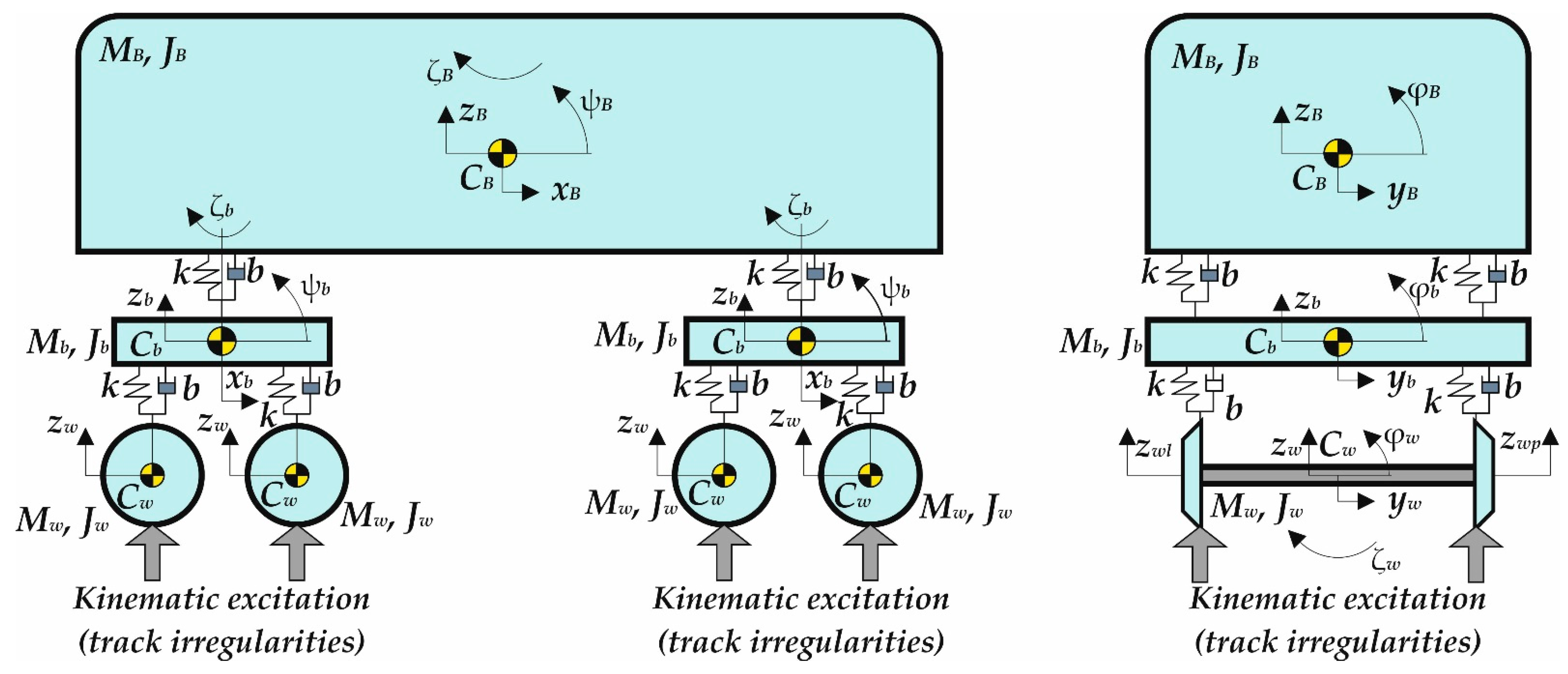
In terms of the mechanics, a considered rail vehicle consists of several rigid bodies connected by force elements (coil springs and hydraulic dampers). Force elements are supposed to be massless. Moreover, between individual bodies are restricted, required degrees of freedom of mechanical joints and kinematic couplings. Between wheels and rails are defined special coupling elements for the calculation of forces and other quantities in the wheel/rail contact [39,40]. In our case, the FASTSIM wheel/rail model is defined [41,42,43]. All force elements, joints, couplings, wheel/rail contact elements and their characteristics are defined symmetrically in relation to the longitudinal symmetry plane. A dynamic scheme of a solved rail vehicle in a side view is shown in Figure 1.
The resulting system of equations of motion consists of non-homogenous differential equations [11,44], which are usually nonlinear and can be written as follows:
where q(t), and are the vector of generalized coordinates, velocities and accelerations, respectively, M is the mass matrix, B is the damping matrix and K is the stiffness matrix. Matrices and describe the gyroscopic and inertia forces.
Figure 1 shows a simplified dynamical scheme of the investigated rail vehicle with the main components marked as follows: MB is the wagon body mass, Mb is the mass of bogies, Mw is the mass of wheelsets, JB is the wagon body moment of inertia, Jb is the moment of inertia of bogies, Jw is the moment of inertia of wheelsets, further, k indicates stiffness of coil springs and b means the damping coefficient of the hydraulic dampers. The masses of rigid bodies are concentrated in their centres of gravity, which are marked by CB for the wagon body, Cb for bogies and Cw for wheelsets. The rest of the quantities indicate generalized coordinates and are marked as follows: for vertical direction of a wagon body (zB), bogies (zb) and wheelsets (zw), for longitudinal direction of bogies (xb), for lateral direction of a wagon body (yB), bogies (yb) and wheelsets (yw); further, generalized coordinates are included for angular deflection around the longitudinal axes for the wagon body (φB), bogies (φb) and wheelsets (φw), around the lateral axis for the wagon body (ψB) and for bogies (ψb), and finally around the vertical axis for the wagon body (ζB), bogies (ζb) and wheelsets (ζw). Generally, the right side of equations of motion describes the external load of a mechanical system, i.e., the excitation of the system [6,7,45]. In the case of the rail vehicle, the excitation is most often caused by track irregularities [46,47,48,49]. Hence, the vector h(t) is the vector of kinematic excitation of the rail vehicle containing parameters of railway track irregularities [50,51]. Due to the symmetry of a rail vehicle, equations of motion can be divided into two separate systems for symmetrical and asymmetrical motions.
3.2. A Railway Track Model
A railway track model for simulation computations needs to have its geometry, flexibility [52,53] as well as its irregularities defined [54,55].
Nominal railway track geometry is defined by its ideal position, which is given by straight track section, curves radii, lengths of individual curves, sections in superelevation ramps and transition sections, rail cants, and others [36,56,57].
A railway track model is supposed to be the definition of rail head profiles and a prescription of input values regarding running on a track, further layout and arrangement of track irregularities and wheel/rail profile wear [1,58]. Ideal track geometry is defined separately from parameters defining real inputs for deviations from the ideal position together with track irregularities.
If a multibody model includes a flexible track model, a track model consists of one rigid body, two rigid bodies or several rigid bodies. Then, these bodies substitute masses of rails and are connected by flexible couplings.
In the Simpack programme package, the railway track is created either directly in the user’s interface or by means of a configuration file. Both contain required parameters as follows:
- A horizontal profile;
- A vertical profile;
- Rail head profiles;
- Track irregularities.
Track irregularities result in kinematic excitations of the rail vehicle mechanical system when it moves on a railway track, and they influence its dynamic response. Usually, track irregularities are described for lateral and vertical direction separately. In the Simpack software, it is possible to prescribe track irregularities by a harmonic function, by the power spectral density or by the input data, which are obtained from real measurements.
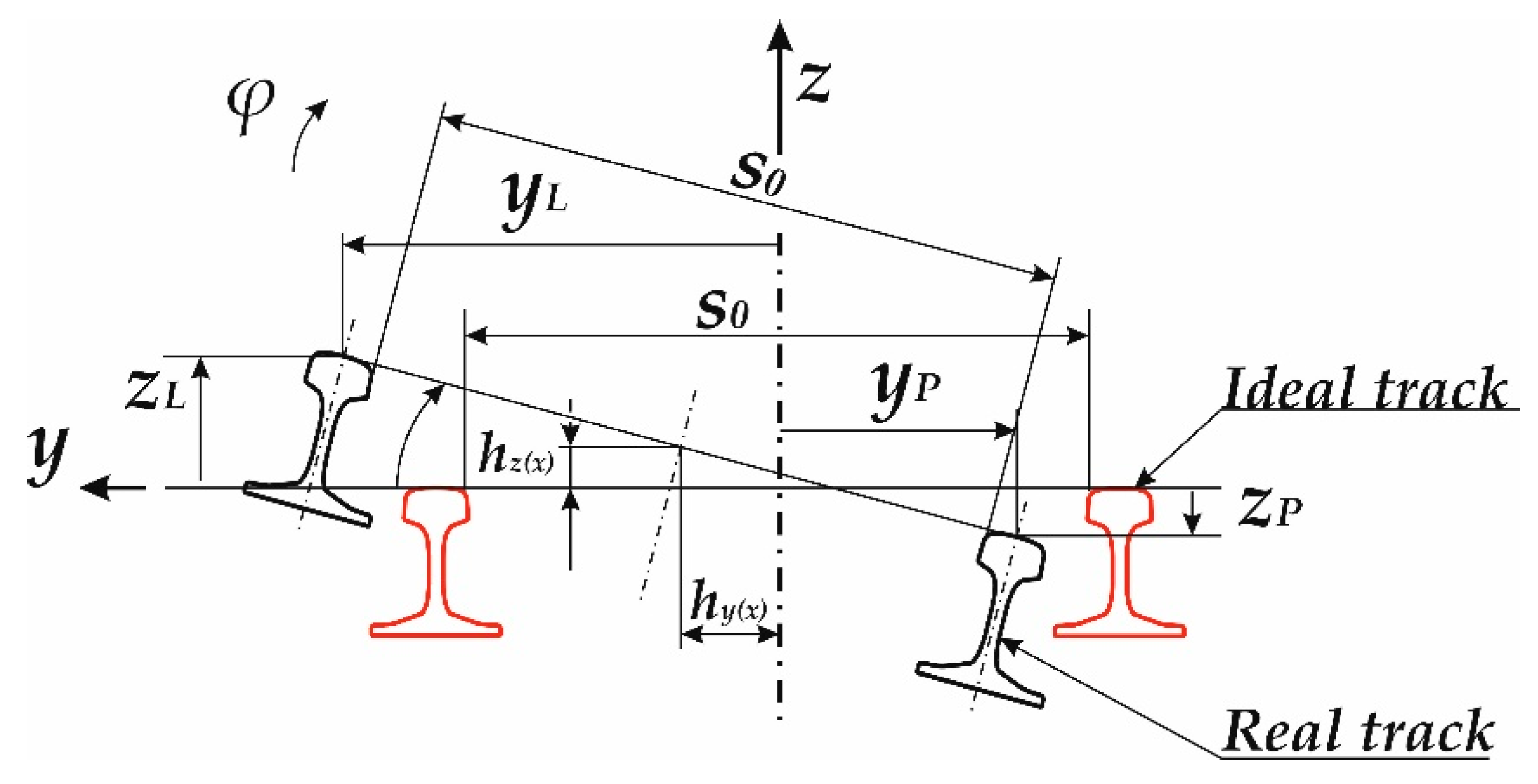
Track irregularities described by a harmonic function are the simplest way. The PSD description simulates track irregularities, which are closer to the reality. The measured track irregularities simulate the most realistic effect to a rail vehicle. Some parameters of track irregularities needed for the input file are shown in Figure 2, where y is the deviation in lateral direction, z is the deviation in the vertical direction, φ is the angle deviation and s0 is the nominal track gauge [59]. Lower indices L and R for deviations (Figure 2) mean left and right rails, respectively. A model of the railway track used in this research includes its flexibility. A more detailed description of the railway track model used in the solved task is introduced in Section 5.2.
4. A Multibody Model of an Investigated Rail Vehicle and a Railway Track
The following section introduces an applied method for the creation of an MBS model of a rail vehicle and a railway track. Both have been within one assembly, and this has been set up by several substructures described below.
4.1. A Description of a Wagon Model
Simulation computations have been performed with a rail vehicle model representing a railway passenger wagon. This wagon model in the Simpack software package comprises three substructures, namely for the body of the wagon, a front bogie and a rear bogie (in the running direction). The wagon is equipped with a two-level suspension system, the first level between the wheelsets and a bogie frame and the second between a bogie frame and the body of the wagon. Both suspension systems consist of coil springs and hydraulic dampers.
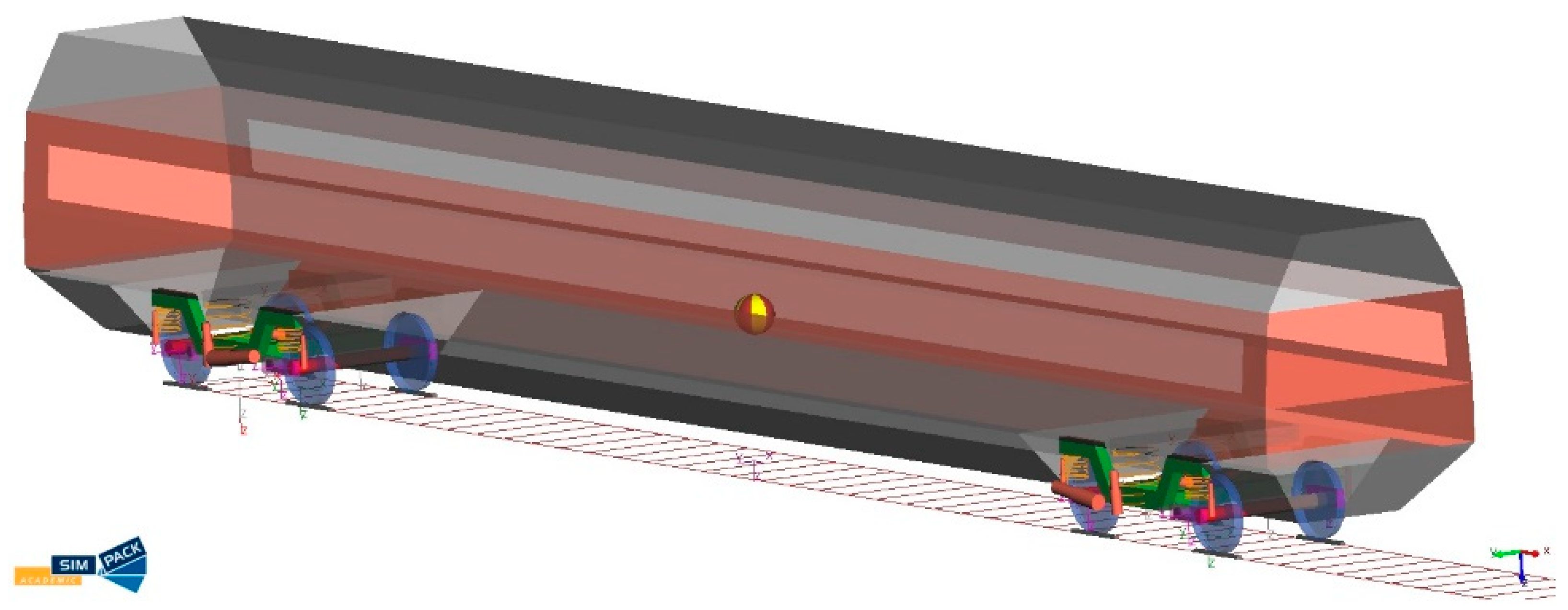
From the mechanics’ point of view, the computational wagon model is created by rigid bodies with defined mass and inertia parameters, and these bodies are interconnected by massless flexible components, which are called force elements in the Simpack. A view of the created multibody model of the passenger wagon is shown in Figure 3.
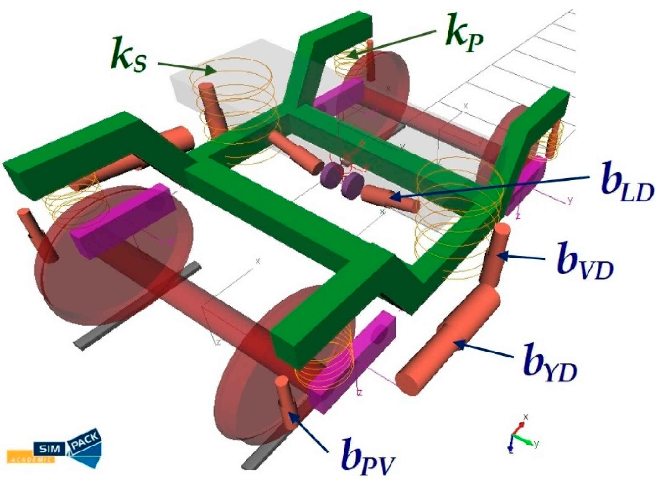
The wagon bogie is shown in Figure 4. It contains a designation of individual components of suspension systems, which are important in relation to other research procedures described below (Section 5). Thus, these components are denoted as follows:
- kP is the stiffness of the primary spring;
- kS is the stiffness of the secondary spring;
- bPV is the damping coefficient of the primary vertical damper;
- bPY is the damping coefficient of the primary yaw damper;
- bPL is the damping coefficient of the primary lateral damper;
- bSV is the damping coefficient of the secondary vertical damper.
4.2. A Description of a Railway Track Model
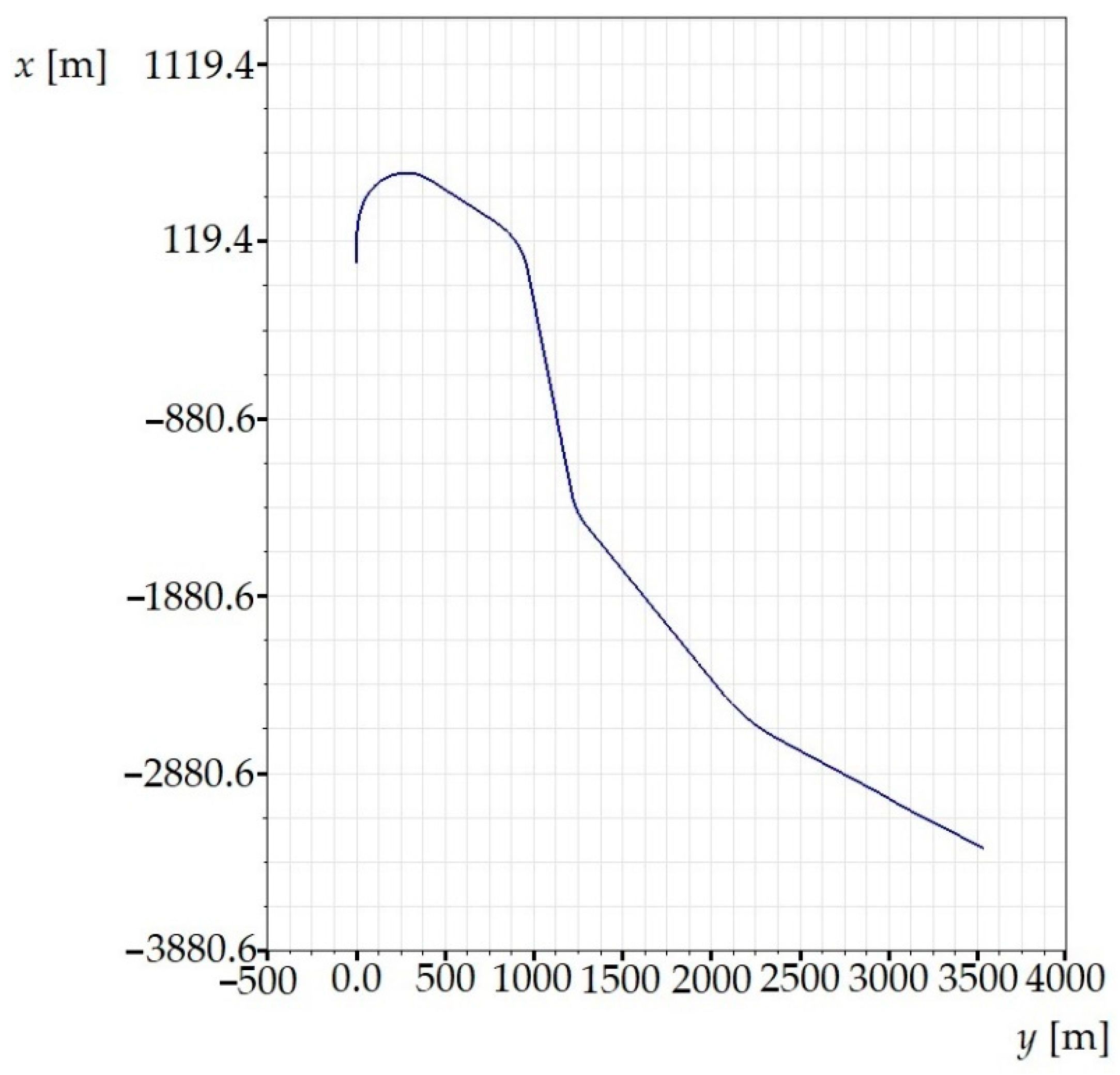
The railway track is another important part of the entire multibody model. In our research, we have chosen a railway track model of a real railway track section. The used track model is suitable for performing the simulation computations needed and subsequent evaluation of dynamical quantities, because it includes not only straight sections, but also sections with curves of various radii, superelevation ramps, transient sections, etc. The track gauge is 1435 mm, the rail head profile is UIC60 and the rail cant is 1:40. There parameters are defined in the track input file. A view of the track in the horizontal plane of the railway track model is shown in Figure 5.
The modelled railway track has defined the kind of superelevation for all curves about the inner side. It means that the inner side of the track remains at the same level, and the outer side is raised by the full superelevation. The track centreline is raised by the half superelevation.
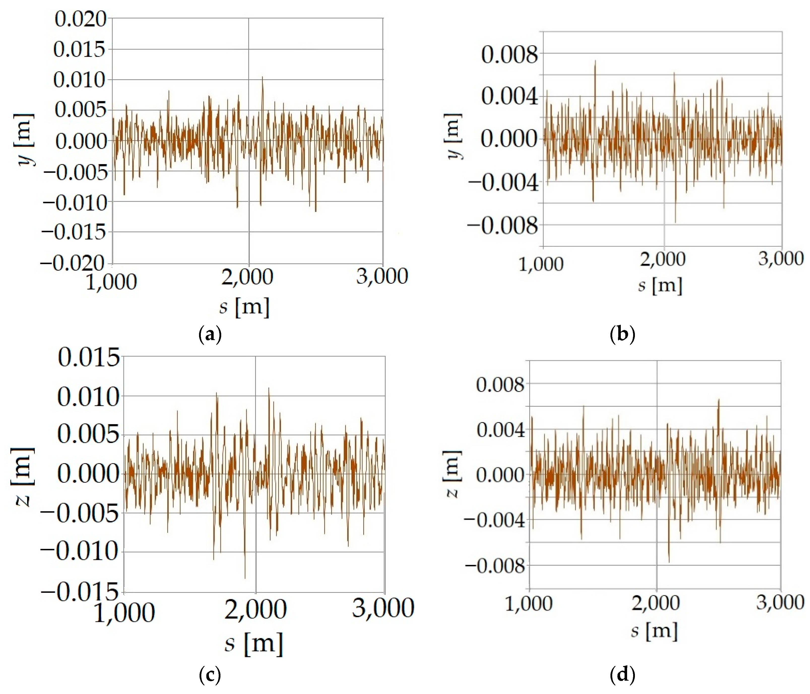
The definition of the railway track model has also incorporated track irregularities. The definition of irregularities in the track model is important in terms of excitation of the passenger car to simulate as real conditions as possible. The model of the railway track used included measured track irregularities in the vertical and horizontal directions of both rails. Track irregularities have been defined by means of an input file, where individual deviations from an ideal geometry are prescribed. The track irregularities have been defined with the step of 0.5 m. An illustration of track irregularities used in the track model is in Figure 6. This track model has led to the generation of rail vehicle excitations and to related observable dynamical effects [60,61,62].
5. Results of Simulation Computations
The main goal of this investigation’s activities is to investigate how the change of suspension parameters of the passenger car affects the dynamic forces and how the track flexibility affects them.
5.1. Influence of Suspension Parameters Changes
Parameters of the coil spring and hydraulic damper of the first level and second level suspension are changed in three manners. There are components of suspension system denoted in Figure 4 (stiffness kP and kS and damping coefficients bVD and bVD). In doing so, the ratio of the stiffness of secondary and primary springs as well as the ratio of the damping of the vertical secondary and the vertical primary dampers have been preserved. Damping coefficients of the rest of the dampers were unchanged. The stiffness characteristics of the springs are linear, and the characteristics of the damping coefficients are non-linear.
The definition of spring-damping parameters that come from the original parameters is named “Original”. The ratio of stiffness kS/kP is 0.587. In the case of damping coefficients, an inclination of the tangent has been changed and the ratio of the extreme values has been preserved. Then, many combinations of the kP and kS, and characteristics of bPV and bVS are defined and tested by means of simulation computations. This work presents only the finally chosen combinations of the kP and kS, and bPV and bSV for illustration of their effects on the dynamical response of the rail vehicle. These parameters are listed in Table 1. The percentage of kP, kS, bPV and bSV expresses what percentage the original value has changed. It has been changed both to a lower (sign “−”) and higher (sign “+”) value.
Simulation computation of the rail vehicle is performed for various running speeds. This section brings waveforms of the derailment quotient for the running speed of 60 km/h. This speed represents an average speed for the chosen track sections, and it sufficiently illustrates the observed results.
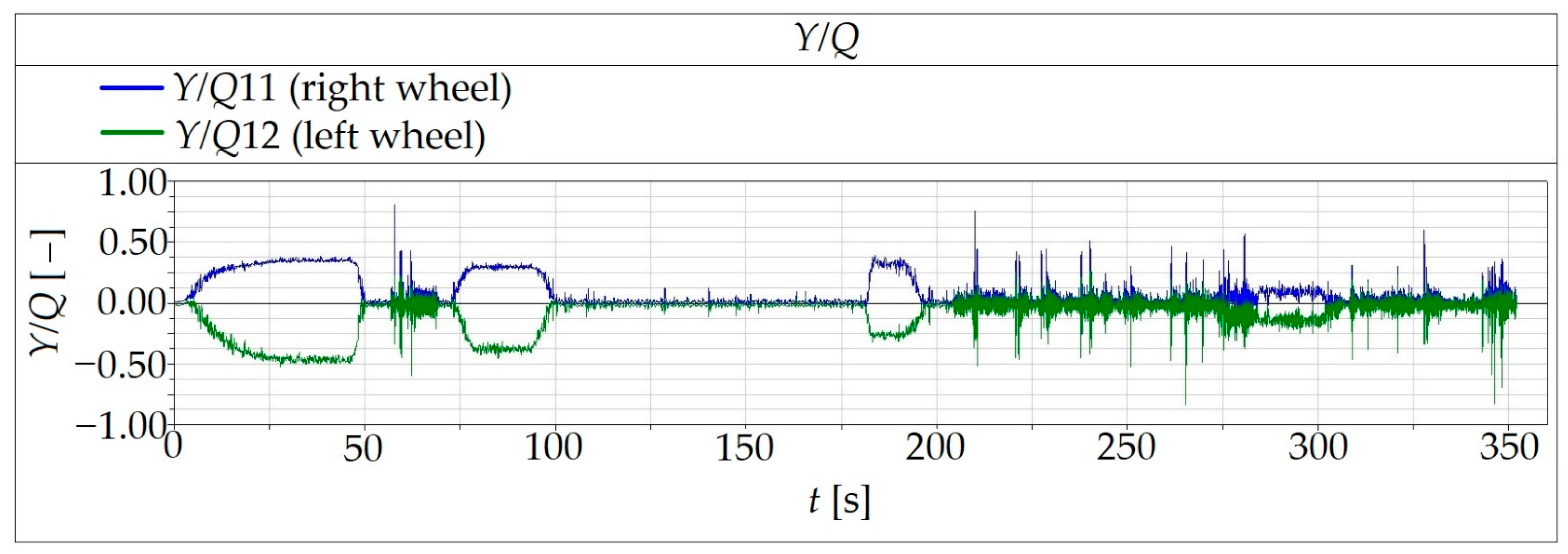
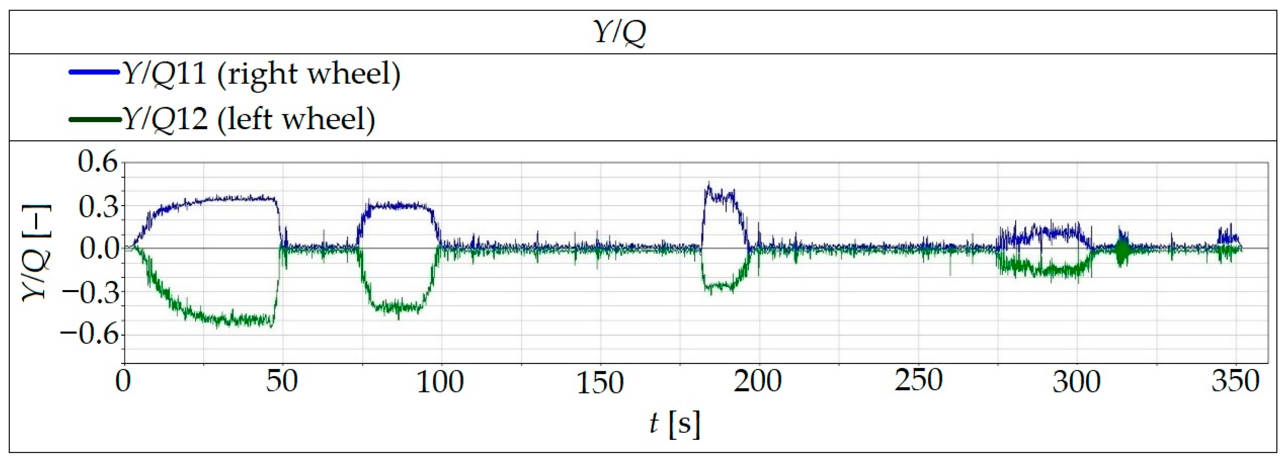
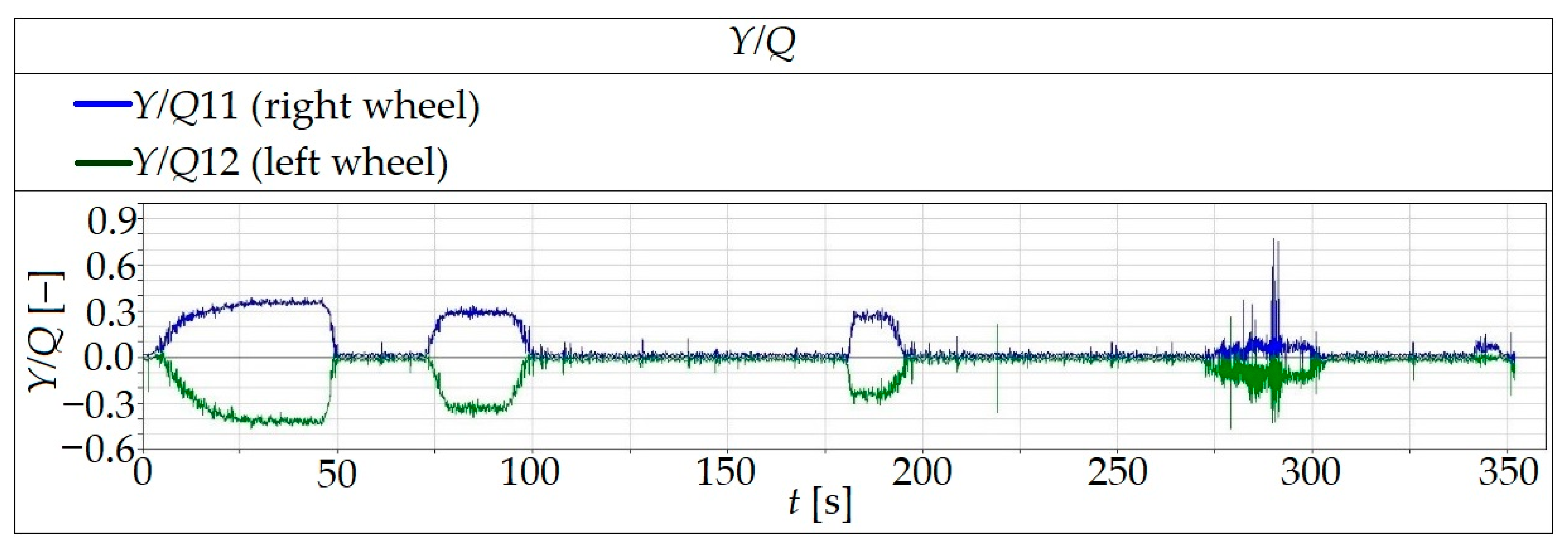
Figure 7, Figure 8 and Figure 9 show waveforms of the output value, i.e., derailment quotient, which is expressed as the Y/Q ratio. As it was mentioned above, it is the key factor for the evaluation of running safety of rail vehicle running in curves. There are displayed results for the original vehicle, modification I and modification II.
The values of the Y/Q ratio in neither case have exceeded the limit value, which is for curves of the track model of Y/Qlim = 0.8 [27,28]. The analysed vehicle ran through curves in all tested cases safely.
As it can be seen, the original suspension system does not ensure the damping of the vehicle after running through curves (Figure 7, the time ranges are 60 s to 70 s and 210 s to 350 s), and amplitudes of the derailment quotient are higher in comparison with results for modification I and modification II.
5.2. Influence of Railway Track Flexibility
Simulations of a rail vehicle in simulation software are usually performed for a rigid railway track. However, there are technical applications, for which it is necessary to consider the fact that a railway track and its subsoil are not ideally rigid, but they have a certain flexibility. Such a multibody model of a rail vehicle and a railway track is supplemented by other bodies, kinematic and mechanical joints with defined degrees of freedom, stiffness-damping parameters in individual directions and others.
The Simpack program package allows us to set up such a model of a flexible railway track, which can be more or less difficult. The formulation of the flexible track is performed in this particular software during the modelling of a bogie, namely during defining wheel/track contact parameters. Then, it is loaded to the entire model of a rail vehicle.
In principle, the stiffness-damping parameters, i.e., stiffness and damping coefficients in joints between individual bodies representing sleepers, can be defined in two manners:
- By defining constant values of stiffness-damping parameters;
- By defining a functional dependency of stiffness-damping parameters; parameters depend on a travelled distance and such an approach takes into account changes of stiffness-damping parameters under sleepers and between sleepers.
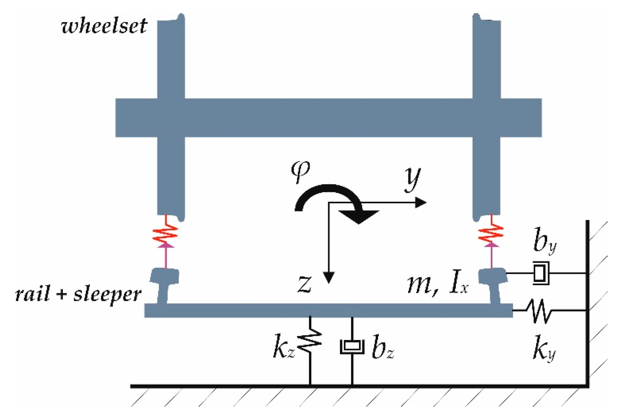
A scheme of a flexible railway track model used in the research is shown in Figure 10.
In the presented work, both approaches of modelling a flexible railway track have been applied. Formulations used for modelling stiffness-damping parameters are as follows:
where ki(L) is the stiffness of the track in individual directions ki(L) (depending on the travelled distance), ki0 is the constant stiffness in individual directions, kiC is the stiffness amplitude, ωL is the frequency, L(t) is the travelled distance, L0 is the offset of the initial input in the track model for smooth convergence of an iteration step, bi(L) is the damping coefficient in individual directions, bi0 is the constant value of the damping coefficient in individual directions and biC is the amplitude of the damping coefficient. The values of stiffness and damping coefficients are defined in the model symmetrically in relation to the longitudinal plane of symmetry, i.e., the same parameters are defined for both right and left sides of the track. Parameters of the elastic track foundation have been defined according to [63]. The stiffness-damping parameters of the flexible track are constant independently of whether it is the straight section or the sections with curves.
To identify the obtained results for various formulations of the railway track models, the following designations are used:
- A rigid track is denoted as “Rigid”;
- A flexible track with constant stiffness-damping parameters is denoted as “Flex_const”;
- A flexible track with variable stiffness-damping parameters is denoted as “Flex_sin”.
Constant values of stiffness-damping parameters for a flexible track model are listed in Table 2.
Parameters of the tested rail vehicle correspond with values for the “Original” vehicle described in Section 5.1.
For assessment of the rail vehicle in terms of running safety and track loading, vertical wheel forces, lateral wheel forces and the described derailment safety are important.
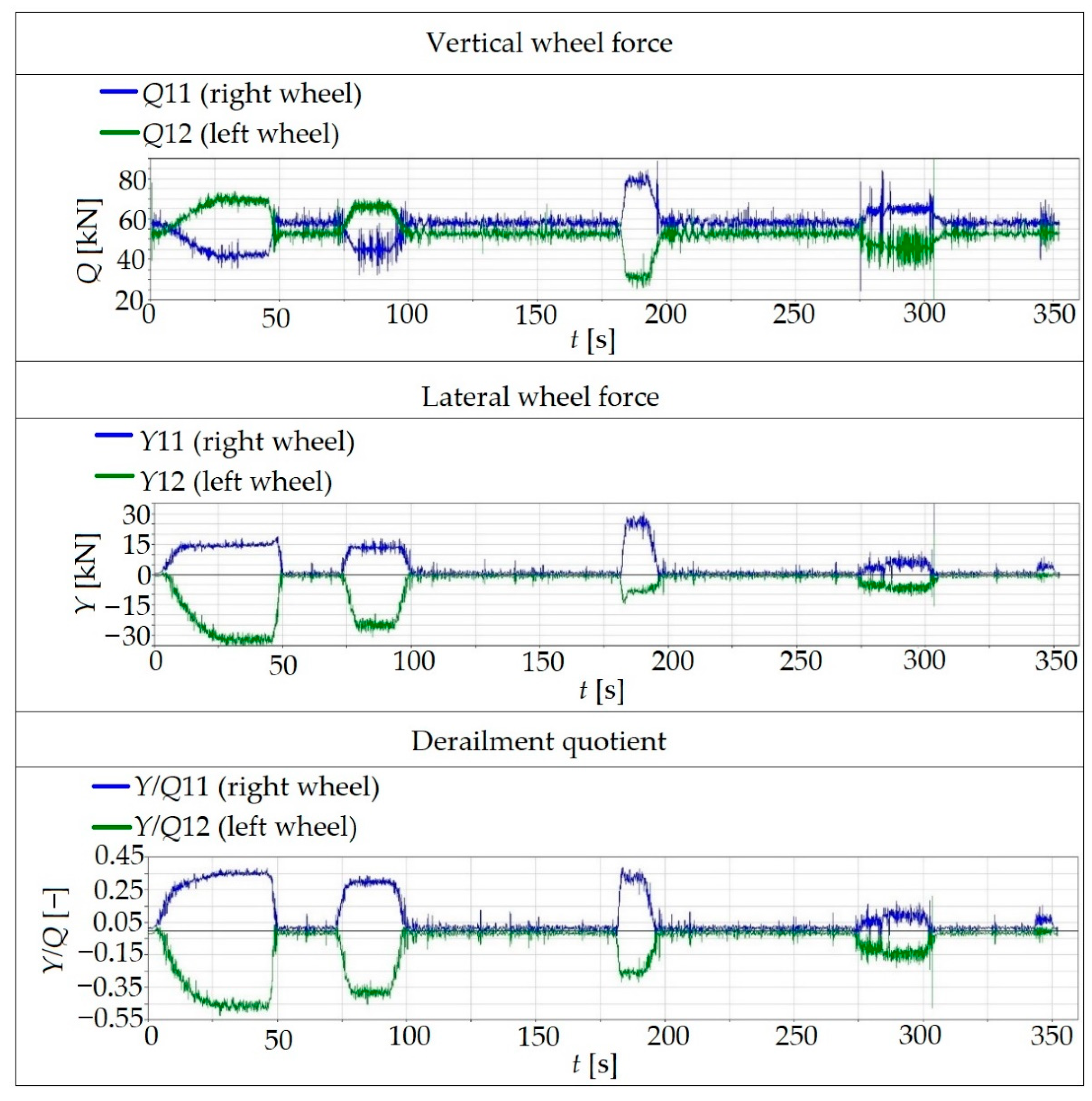
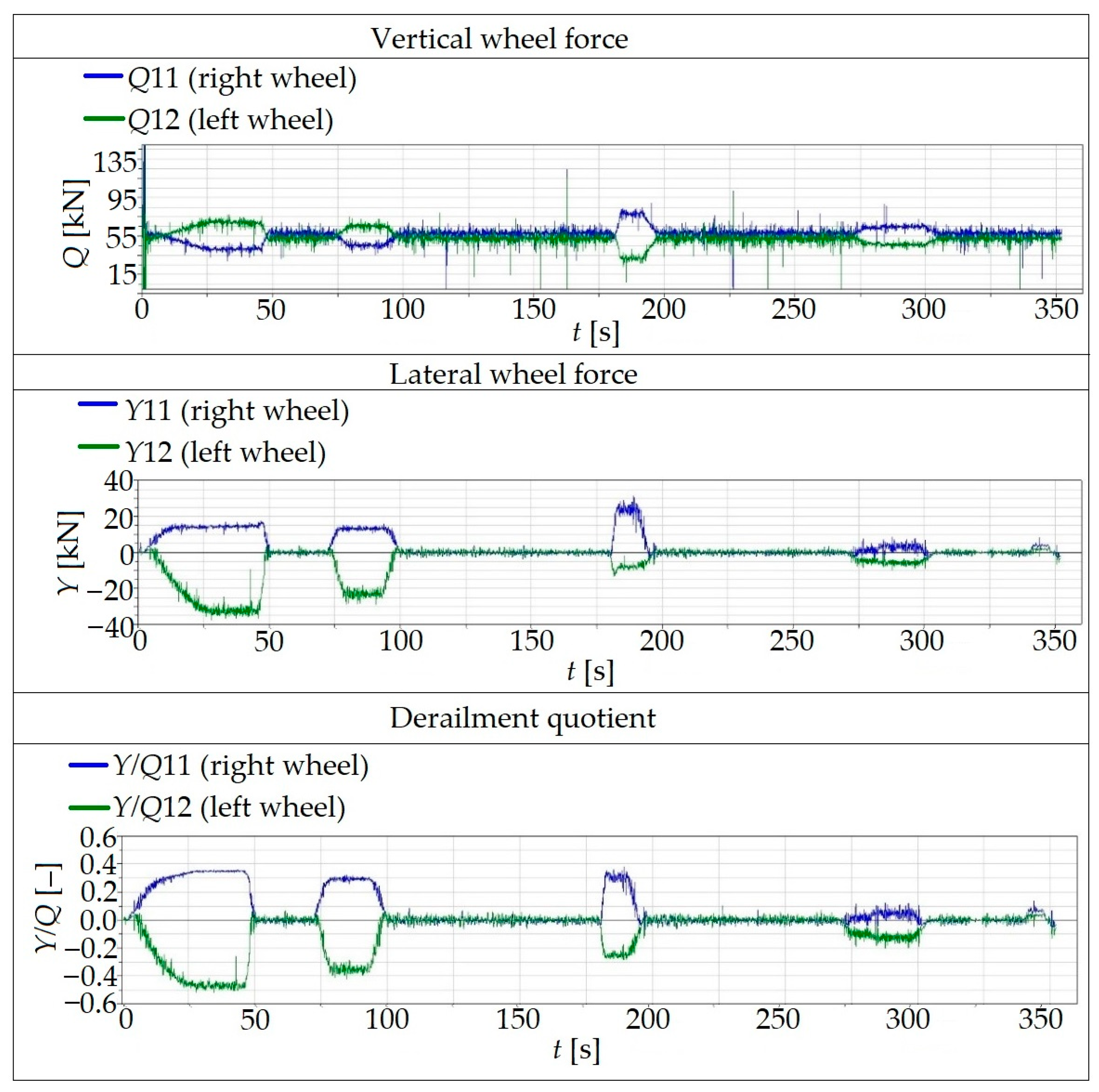
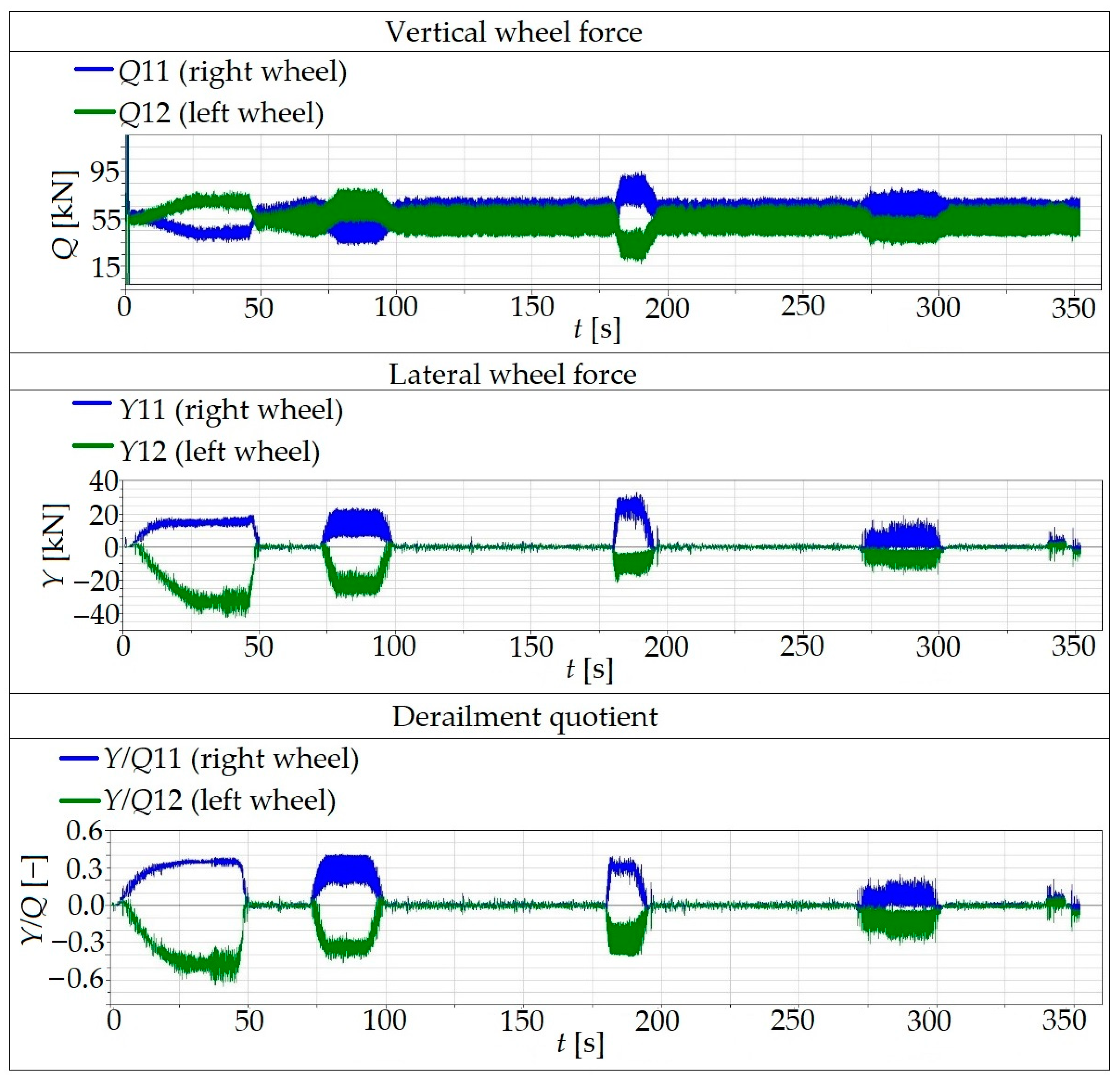
Resulting waveforms of vertical wheel forces, lateral wheel forces and derailment quotient for the set running conditions are shown in Figure 11, Figure 12 and Figure 13. Results are for the running speed of 60 km/h and for the “Rigid”, “Flex_const” and “Flex_sin” track formulations.
When the observed wheel force waveforms are evaluated for different track formulations, it can be seen that the use of the flexible track model with constant values of stiffness-damping characteristics (“Flex_const”) leads to partial damping of dynamical effects of the running rail vehicle. Amplitudes of vertical wheel forces (Q) are lower mainly while running in curves. The higher damping effect is also registered for lateral wheel forces (Y) as well as for the derailment quotient (Y/Q). The derailment quotient is higher for running in curves in comparison with running in straight track sections.
Achieved results of simulation computations have shown that amplitudes of the vertical wheel forces Q, the lateral wheel forces Y and thus also the values of resulting derailment quotient Y/Q are significantly higher for the flexible formulation (“Flex_sin”) of a railway track in comparison with the results for the “Rigid” track formulation and for the “Flex_const” track formulation. It is possible to conclude that these higher amplitudes are caused by the variable parameters along the track. The model used does not describe the real situation of the actual railway track. This phenomenon can be improved by an implementation of values obtained directly from experimental measurements on a particular track section. Such parameters could replace the input data in the current model of the railway track.
The presented work shows the possibilities of creating an adequate model of a rail vehicle and a railway track with track flexibility. The objective of the authors’ work is based on a close collaboration with researchers from the university to obtain parameters of railway tracks from real railway track sections as well as vehicle operated on these lines. These parameters will be real inputs for simulation models, which will serve for the calculation of certain problematic track sections. Potential adequate results from simulation computations will be useful for building or reconstructing railway tracks, and the unwanted behaviour of railway track substructure after a train passes will be detected before expensive construction interventions [64,65].
6. Conclusions
Computer simulations are widely used for the investigation and assessment of dynamic effects of rail vehicles while running on a railway track.
Analysis of running safety is still a current problem and a distribution of forces in wheel/rail contact is very important. Here, we investigated mainly vertical wheel forces in terms of the track loads and lateral forces, which determine running safety during movement in curves. Then, the ratio of vertical wheel forces and lateral wheel forces gives the derailment quotient, and the limit values are included in the specific standards.
In the presented research:
- The commercial simulation software Simpack has been used for the creation of a multibody model of a rail vehicle;
- A virtual model of a passenger car as well as a railway track model with track flexibility has been set up;
- The dynamic forces and the derailment ratio have been evaluated for three levels of stiffness-damping coefficients of the rail vehicle and for three various track flexibility formulations;
- It was concluded that the stiffness of springs and damping coefficients of dampers of the primary suspension leads to better damping of the rail vehicle mechanical system while running on a track. In the case of the flexible track formulation, the definition of stiffness-damping parameters of the track subsoil leads to higher amplitudes in comparison with the rigid track formulation.
Author Contributions
Conceptualization, J.D., M.B., J.H. and A.S.; methodology, J.D. and M.B.; software, J.D. and J.H.; validation, M.B. and A.S.; formal analysis, J.D., J.H. and A.S.; investigation, M.B. and A.S.; resources, J.D., M.B. and J.H.; data curation, J.D.; writing—original draft preparation, J.D. and A.S.; writing—review and editing, M.B. and J.H.; visualization, J.D., J.H. and A.S.; funding acquisition, J.D. All authors have read and agreed to the published version of the manuscript.
Funding
This research was supported by the Cultural and Educational Grant Agency of the Ministry of Education of the Slovak Republic under project No. KEGA 023ŽU-4/2020: Development of advanced virtual models for the studying and investigation of transport means operation characteristics. This research was supported by the Cultural and Educational Grant Agency of the Ministry of Education of the Slovak Republic under project No. KEGA 036ŽU-4/2021: Implementation of modern methods of computer and experimental analysis of the properties of vehicle components in the education of future vehicle designers. This research was supported by the Cultural and Educational Grant Agency of the Ministry of Education of the Slovak Republic under project No. VEGA 1/0513/22: Investigation of the properties of railway brake components in simulated operating conditions on a flywheel brake stand.
Institutional Review Board Statement
Not applicable.
Informed Consent Statement
Not applicable.
Data Availability Statement
Not applicable.
Conflicts of Interest
The authors declare no conflict of interest.
References
- Šťastniak, P.; Smetanka, L.; Drozdziel, P. Computer aided simulation analysis for wear investigation of railway wheel running surface. Diagnostyka 2019, 20, 63–68. [Google Scholar]
- Yu, Y.W.; Zhao, L.L.; Zhou, C.C. A new vertical dynamic model for railway vehicle with passenger-train-track coupling vibration. Proc. Inst. Mech. Eng. Part K-J. Multibody Dyn. 2020, 234, 134–146. [Google Scholar] [CrossRef]
- Wu, Y.; Zeng, J.; Qu, S.; Shi, H.L.; Wang, Q.S.; Wei, L. Low-frequency carbody sway modelling based on low wheel-rail contact conicity analysis. Shock Vib. 2020, 2020, 71049. [Google Scholar] [CrossRef]
- Leitner, B. A new approach to identification and modelling of machine dynamic systems behaviour. In Proceedings of the 14th International Conference Transport Means, Kaunas, Lithuania, 21–22 October 2010. [Google Scholar]
- Leitner, B.; Mocova, L.; Hromada, M. A new approach to identification of critical elements in railway infrastructure. In Proceedings of the 10th International Scientific Conference on Transportation Science and Technology (Transbaltica), Vilnius, Lithuania, 4–5 May 2017. [Google Scholar]
- Saga, M.; Jakubovicova, L. Simulation of vertical vehicle non-stationary random vibrations considering various speeds. Sci. J. Sil. Univ. Technol. Ser. Transp. 2014, 84, 113–118. [Google Scholar]
- Saga, M.; Vasko, M.; Handrik, M.; Kopas, P. Contribution to random vibration numerical simulation and optimisation of nonlinear mechanical systems. Sci. J. Sil. Univ. Technol. Ser. Transp. 2019, 103, 143–154. [Google Scholar] [CrossRef]
- Jakubovicova, L.; Sapietova, A.; Moravec, J. Static analysis of transmission tower beam structure. In Proceedings of the 3rd International Scientific Conference on Innovative Technologies in Engineering Production (ITEP), Bojnice, Slovakia, 11–13 September 2018. [Google Scholar]
- Koziak, S.; Chudzikiewicz, A.; Opala, M.; Melnik, R. Virtual software testing and certification of railway vehicle from the point of view of their dynamics. In Proceedings of the 13th International Scientific Conference on Sustainable, Modern and Safe Transport (Transcom), Novy Smokovec, Slovakia, 29–31 May 2019. [Google Scholar]
- Melnik, R.; Sowinski, B. Analysis of dynamics of a metro vehicle model with differential wheelsets. Transp. Probl. 2017, 12, 113–124. [Google Scholar] [CrossRef] [Green Version]
- Shevtsov, Y.I. Wheel/Rail Interface Optimisation; Delft University of Technology: Delft, The Netherlands, 2008. [Google Scholar]
- Muñoz, S.; Aceituno, J.F.; Urda, P.; Escalona, J.L. Multibody model of railway vehicles with weakly coupled vertical and lateral dynamics. Mech. Syst. Signal Process. 2019, 115, 570–592. [Google Scholar] [CrossRef]
- Lack, T.; Gerlici, J.; Maňurová, M. Freight car bogie properties analysis by means of simulation computations. Manuf. Technol. 2016, 16, 733–739. [Google Scholar] [CrossRef]
- Gerlici, J.; Lack, T. Modified HHT method for vehicle vibration analysis in time domain utilization. Appl. Mech. Mater. 2014, 486, 396–405. [Google Scholar] [CrossRef]
- Gerlici, J.; Sakhno, V.; Yefymenko, A.; Verbitskii, V.; Kravchenko, A.; Kravchenko, K. The stability analysis of two-wheeled vehicle model. In Proceedings of the 22nd Slovak-Polish Scientific Conference on Machine Modelling and Simulations (MMS), Sklene Teplice, Slovakia, 5–8 September 2017. [Google Scholar]
- Chudzikiewicz, A.; Opala, M. Application of computer simulation methods for running safety assessment of railway vehicles in example of freight cars. New Trends Mech. Transp. 2008, 9, 63–71. [Google Scholar] [CrossRef]
- Opala, M. Analysis of experimental data in the context of safety against derailment of a railway vehicle, using the energy method. Key Eng. Mater. 2012, 518, 16–23. [Google Scholar] [CrossRef]
- Opala, M. Statistical inference of the railway vehicle running safety using monitoring data. In Proceedings of the Mini Conference on Vehicle System Dynamics, Identification and Anomalies, Budapest, Hungary, 5–7 November 2012. [Google Scholar]
- Bureika, G.; Levinzon, M.; Dailydka, S.; Steisunas, S.; Zygiane, R. Evaluation criteria of wheel/rail interaction measurement results by trackside control equipment. Int. J. Heavy Veh. Syst. 2019, 26, 747–764. [Google Scholar] [CrossRef]
- Sowiński, B.; Stelmach, A.; Chudzikiewicz, A. Simulation analysis of the influence of changes in track parameters on running safety of a rail vehicle. Energies 2021, 14, 5882. [Google Scholar] [CrossRef]
- Smetanka, L.; Dižo, J.; Šťastniak, P.; Blatnický, M. Wear calculation of wheel tread surface of a rail vehucle by means of the SIMPACK programe. Railw. Transp. Logist. Sci. Tech. J. Railw. Transp. Logist. Manag. 2017, 13, 19–24. (In Slovak) [Google Scholar]
- Smetanka, L.; Šťastniak, P.; Dižo, J. Comparison of wear laws programed in the SIMPACK software. In Proceedings of the Experimental and Calculation Methods in Engineering, Ústí Nad Labem, Czech Republic, 22–23 June 2017. (In Slovak). [Google Scholar]
- Dižo, J. Evaluation of ride comfort for passengers by means of computer simulation. Manuf. Technol. 2015, 15, 8–14. [Google Scholar] [CrossRef]
- Dižo, J.; Blatnický, M. Investigation of ride properties of a three-wheeled electric vehicle in terms of driving safety. In Proceedings of the 13th International Scientific Conference on Sustainable, Modern and Safe Transport (TRANSCOM 2019), Novy Smokovec, Slovakia, 29–31 May 2019; Bujnak, J., Guagliano, M., Eds.; Elsevier: Amsterdam, The Netherlands, 2019. [Google Scholar]
- Dižo, J.; Blatnický, M. Evaluation of vibrational properties of a three-wheeled vehicle in terms of comfort. Manuf. Technol. 2019, 19, 197–203. [Google Scholar]
- Dižo, J.; Blatnický, M.; Steišūnas, S.; Skočilasová, B. Assessment of a rail vehicle running with the damaged wheel on a ride comfort for passengers. In Proceedings of the Machine Modelling and Simulations, Sklene Teplice, Slovakia, 5–8 September 2017. [Google Scholar]
- EN 14363: Railway Applications—Testing for the Acceptance of Running Characteristics of Railway Vehicles (2005) Testing of Running Behavior and Stationary Tests; European Committee for Standardization: Brussels, Belgium, 2005.
- Testing and Approval of Railway Vehicles from the Point of View of Their Dynamic Behavior (2003) Safety—TRACK Fatigue—RIDE Quality; UIC Code 518; International Union of Railways: Paris, France, 2003.
- Zhai, W. Vehicle–Track Coupled Dynamics; Springer: Singapore, 2020. [Google Scholar]
- Song, Y.; Wang, Z.; Liu, Z.; Wang, R. A spatial coupling model to study dynamic performance of pantograph-catenary with vehicle-track excitation. Mech. Syst. Signal Process. 2021, 151, 107336. [Google Scholar] [CrossRef]
- Kisilowski, J.; Kowalik, R. Mechanical wear contact between the wheel and rail on a turnout with variable stiffness. Energies 2021, 14, 7520. [Google Scholar] [CrossRef]
- Izvolt, L.; Dobes, P.; Drusa, M.; Kadela, M.; Holesova, M. Experimental and numerical verification of the railway track substructure with innovative thermal insulation materials. Materials 2022, 15, 160. [Google Scholar] [CrossRef]
- Pavlik, A.; Gerlici, J.; Lack, T.; Hauser, V.; Šťastniak, P. Prediction of the rail-wheel contact wear of an innovative bogie by simulation analysis. Transp. Res. Procedia 2019, 40, 855–860. [Google Scholar] [CrossRef]
- Lack, T.; Gerlici, J.; Stastniak, P. Wheelset/rail geometric characteristics and contact forces assessment with regard to angle of attack. In Proceedings of the 23rd Polish-Slovak Scientific Conference on Machine Modelling and Simulations (MMS), Rydzyna, Slovakia, 4–7 September 2018. [Google Scholar]
- Hauser, V.; Nozhenko, O.; Kravchenko, K.; Loulova, M.; Gerlici, J.; Lack, T. Proposal of a steering mechanism of a tram bogie with three axle boxes. In Proceedings of the 12th International Scientific Conference of Young Scientists on Sustainable, Modern and Safe Transport, High Tatras, Slovakia, 31 May–1 June 2017. [Google Scholar]
- Šťastniak, P. Freight long wagon dynamic analysis in S-curve by means of computer simulation. Manuf. Technol. J. Sci. Res. Prod. 2015, 15, 930–935. [Google Scholar] [CrossRef]
- Lack, T.; Gerlici, J. Modified strip method utilization for wheel/rail contact stress evaluation. In Proceedings of the 9th International Conference on Contact Mechanics and Wear of Rail/Wheel Systems (CM), Chengdu, China, 27–30 August 2012; pp. 87–89. [Google Scholar]
- Mikaliunas, Š.; Lingaltis, L.P.; Vaičiunas, G. The analysis of wear intensity of lubricated and unlubricated locomotive wheelsets flanges. Transport 2004, 19, 32–39. [Google Scholar] [CrossRef] [Green Version]
- Vaičiunas, G.; Steišiunas, S. Sperlings comfort index study in a passenger car with independently rotating wheels. Transp. Probl. 2021, 16, 121–130. [Google Scholar] [CrossRef]
- Gerlici, J.; Lack, T. Contact of the Railway Wheelset and a Track, 1st ed.; University of Žilina: Žilina, Slovakia, 2004. (In Slovak) [Google Scholar]
- Mikhailov, E.; Sapronova, S.; Tkachenko, V.; Semenov, S.; Smyrnova, I.; Kholostenko, Y. Improved solution of guiding of railway vehicle in curves. In Proceedings of the 23rd International Scientific Conference on Transport Means 2019 (TRANSPORT MEANS 2019), Palanga, Lithuania, 2–4 October 2019. [Google Scholar]
- Mikhailov, E.; Semenov, S.; Sapronova, S.; Tkachenko, V. On the issue of wheel flange sliding along the rail. In Proceedings of the 11th Tarnsbaltica International Scientific Conference, Vilnius, Lithuania, 2–3 May 2019. [Google Scholar]
- Kapitsa, M.; Mikhailov, E.; Kliuiev, S.; Semenov, S.; Kovtanets, M. Study of rail vehicles moveemnt characteristics improvement in curves using fuzzy mechantronic systems. In Proceedings of the 2nd International Scientiifc and Practical Conference on Energy-Optimal Technologies, Logistic and Safery on Transport (EOT), Lviv, Ukraine, 19–20 September 2019. [Google Scholar]
- Nangolo, N.F.; Klimenda, F. System identification for underdamped mechanical systems. In Proceedings of the 52nd International Conference on Experimental Stress Analysis (EAN 2014), Marianske Lazne, Czech Republic, 2–5 June 2014. [Google Scholar]
- Kostrzewski, M. Analysis of selected acceleration signals measurements obtained during supervised service conditions—Study of hitherto approach. J. Vibroeng. 2018, 20, 1850–1866. [Google Scholar] [CrossRef] [Green Version]
- Klimenda, F.; Soukup, J.; Skošilasová, B.; Skošilas, J. Vertical vibration of the vehicle when crossing over transverse speed bumps. Manuf. Technol. 2020, 20, 55–59. [Google Scholar] [CrossRef]
- Chudzikiewicz, A.; Bogacz, R.; Kostrzewski, M. Using acceleration signals recorded on a railway vehicle wheelsets for rail track condition monitoring. In Proceedings of the 7th European Workshop on Structural Health Monitoring (EWSHM), 2nd European Conference of the Prognostics and Health Management Society (PHM), Nantes, France, 8–11 July 2014. [Google Scholar]
- Fomin, O.; Lovska, A.; Píštek, V.; Kučera, P. Dynamic load effect on the transportation safety of tank containers as part of combined trains on railway ferries. Vibroeng. Procedia 2019, 29, 124–129. [Google Scholar] [CrossRef]
- Fomin, O.; Lovska, A. Determination of dynamic loading of bearing structures of freight wagons with actual dimensions. East Eur. J. Enterp. Technol. 2021, 2, 6–14. [Google Scholar] [CrossRef]
- Gorbunov, M.; Kravchenko, K.; Kara, S.; Gerlici, J.; Bureika, G.; Steišunas, S. Theory and practice of the innovative spring suspension design for locomotive to improve its traction and dynamic characteristics. In Proceedings of the 22nd International Scientific Conference on Transport Means, Trakai, Lithuania, 3–5 October 2018. [Google Scholar]
- Fomin, O.; Vatulia, G.; Gerlici, J.; Kravchenko, K. Stability study of tank containers placed on a roll-trailer during transportation by railway ferry. Transnav 2021, 15, 315–319. [Google Scholar] [CrossRef]
- Grassie, S.L.; Cox, S.J. The dynamic response of railway track with flexible sleepers to high frequency vertical excitation. Proc. Inst. Mech. Eng. Part D J. Automob. Eng. 1984, 198, 117–124. [Google Scholar] [CrossRef]
- Moravčík, M. Vertical track stiffness effect on dynamic behaviour of track structure. Commun. Sci. Lett. Univ. Žilina 2004, 6, 10–16. [Google Scholar]
- Ning, J.; Lin, J.; Zhang, B. Time-frequency processing of track irregularities in high-speed train. Mech. Syst. Signal Process. 2019, 66–67, 339–348. [Google Scholar] [CrossRef]
- Lei, X.; Noda, N.A. Analyses of dynamic response of vehicle and track coupling with random irregularity of track vertical profile. J. Sound Vib. 2002, 258, 147–165. [Google Scholar] [CrossRef]
- Bitterer, L. A Track Geometry; University of Žilina: Žilina, Slovakia, 1997. (In Slovak) [Google Scholar]
- Wicknes, A.H. Fundamentals of Rail Vehicle Dynamics: Guidance and Stability; Swets & Zeitlinger B.V.: Lisse, Japan, 2003. [Google Scholar]
- Berggren, E.G.; Li, M.X.; Spännar, J. A new approach to the analysis and presentation of vertical track geometry quality and rail roughness. Wear Int. J. Sci. Technol. Frict. Lubr. Wear 2008, 265, 1488–1496. [Google Scholar] [CrossRef]
- Kalinčák, D.; Gerlici, J.; Kukuča, P.; Lábaj, J.; Lack, T.; Polách, O.; Sága, M. A Transport Means—Computational Methods; EDIS: Žilina, Slovakia, 2005. (In Slovak) [Google Scholar]
- Pombo, J.; Ambrósio, J. An alternative method to include track irregularities in railway vehicle dynamic analyses. Nonlinear Dyn. 2012, 68, 161–176. [Google Scholar] [CrossRef]
- Panunzio, A.M.; Puel, G.; Cottereau, R.; Simon, S.; Quost, X. Construction of a stochastic model of track geometry irregularities and validation through experimental measurements of dynamic loading. Veh. Syst. Dyn. 2017, 55, 399–426. [Google Scholar] [CrossRef]
- Javaid, O.; Choi, D.H. Effect of Track Irregularities on the Response of Two-Way Railway Tracks. Appl. Sci. 2020, 10, 11. [Google Scholar] [CrossRef] [Green Version]
- N.N.: Benchmark Problem Results and Assessment. In Bogies with Steered or Steering Wheelsets; ORE (ERRI) B 176/3, DT290; ORE (ERRI): Utrecht, The Netherlands, 1993.
- Milosevic, M.D.G.; Pålsson, B.A.; Nissen, A.; Nielsen, J.C.O.; Johansson, H. Condition monitoring of railway crossing geometry via measured and simulated track responses. Sensors 2022, 22, 1012. [Google Scholar] [CrossRef]
- Sañudo, R.; Jardí, I.; Martínez, J.-C.; Sánchez, F.J.; Miranda, M.; Alonso, B.; dell’Olio, L.; Moura, J.-J. Monitoring track transition zones in Railways. Sensors 2022, 22, 76. [Google Scholar] [CrossRef]
Figure 1.
A dynamical scheme of the solved rail vehicle.

Figure 2.
Parameters of railway track irregularities [59].
Figure 2.
Parameters of railway track irregularities [59].

Figure 3.
A view of the multibody model of the investigated passenger wagon created in the Simpack software package.
Figure 3.
A view of the multibody model of the investigated passenger wagon created in the Simpack software package.

Figure 4.
The wagon bogie with denoted of individual components of suspension systems.

Figure 5.
An illustration of the created railway track.

Figure 6.
An illustration of the parts of the track irregularities prescribed in the track model: (a) a left rail, a lateral direction; (b) a right rail, a lateral direction; (c) a left rail, a vertical direction; (d) a right rail, a vertical direction.
Figure 6.
An illustration of the parts of the track irregularities prescribed in the track model: (a) a left rail, a lateral direction; (b) a right rail, a lateral direction; (c) a left rail, a vertical direction; (d) a right rail, a vertical direction.

Figure 7.
The derailment quotient Y/Q for “Original” parameters, a real track with irregularities, a running speed of 60 km/h.
Figure 7.
The derailment quotient Y/Q for “Original” parameters, a real track with irregularities, a running speed of 60 km/h.

Figure 8.
The derailment quotient Y/Q for “Modification I” parameters, a real track with irregularities, a running speed of 60 km/h.
Figure 8.
The derailment quotient Y/Q for “Modification I” parameters, a real track with irregularities, a running speed of 60 km/h.

Figure 9.
The derailment quotient Y/Q for “Modification II” parameters, a real track with irregularities, a running speed of 60 km/h.
Figure 9.
The derailment quotient Y/Q for “Modification II” parameters, a real track with irregularities, a running speed of 60 km/h.

Figure 10.
A scheme of a flexible railway track model used in the solved task.

Figure 11.
Waveforms of the vertical wheel forces (Q), lateral wheel forces (Y) and derailment quotient (Y/Q) for the “Rigid” track.
Figure 11.
Waveforms of the vertical wheel forces (Q), lateral wheel forces (Y) and derailment quotient (Y/Q) for the “Rigid” track.

Figure 12.
Waveforms of the vertical wheel forces (Q), lateral wheel forces (Y) and derailment quotient (Y/Q) for the “Flex_const” track.
Figure 12.
Waveforms of the vertical wheel forces (Q), lateral wheel forces (Y) and derailment quotient (Y/Q) for the “Flex_const” track.

Figure 13.
Waveforms of the vertical wheel forces (Q), lateral wheel forces (Y) and derailment quotient (Y/Q) for the “Flex_sin” track.
Figure 13.
Waveforms of the vertical wheel forces (Q), lateral wheel forces (Y) and derailment quotient (Y/Q) for the “Flex_sin” track.


Table 1.
List of parameters of the spring-damper elements.
| Stiffness | Damping | ||||
|---|---|---|---|---|---|
| Designation | Name | kP | kS | bPV | bSV |
| O | Original | 0% | 0% | 0% | 0% |
| I | Modification I | −45% | +45% | −45% | +45% |
| II | Modification II | +45% | −45% | +45% | −45% |
Table 2.
Parameters of the flexible railway track model [63].
Table 2.
Parameters of the flexible railway track model [63].
| Parameter | Designation | Value |
|---|---|---|
| Stiffness in the vertical direction | kz | 1.49 × 10⁸ N/m |
| Damping in the vertical direction | bz | 2.10 × 10⁵ Ns/m |
| Stiffness in the lateral direction | ky | 4.21 × 10⁷ N/m |
| Damping in the lateral direction | by | 10.12 × 10⁴ Ns/m |
| Torsion stiffness (around x axis) | kφ | 8.77 × 10⁷ Nm/rad |
| Torsion damping (around x axis) | bφ | 1.25 × 10⁵ Nms/rad |
Publisher’s Note: MDPI stays neutral with regard to jurisdictional claims in published maps and institutional affiliations. |
© 2022 by the authors. Licensee MDPI, Basel, Switzerland. This article is an open access article distributed under the terms and conditions of the Creative Commons Attribution (CC BY) license (https://creativecommons.org/licenses/by/4.0/).
Share and Cite
MDPI and ACS Style
Dižo, J.; Blatnický, M.; Harušinec, J.; Suchánek, A. Assessment of Dynamics of a Rail Vehicle in Terms of Running Properties While Moving on a Real Track Model. Symmetry 2022, 14, 536. https://0-doi-org.brum.beds.ac.uk/10.3390/sym14030536
AMA Style
Dižo J, Blatnický M, Harušinec J, Suchánek A. Assessment of Dynamics of a Rail Vehicle in Terms of Running Properties While Moving on a Real Track Model. Symmetry. 2022; 14(3):536. https://0-doi-org.brum.beds.ac.uk/10.3390/sym14030536
Chicago/Turabian StyleDižo, Ján, Miroslav Blatnický, Jozef Harušinec, and Andrej Suchánek. 2022. "Assessment of Dynamics of a Rail Vehicle in Terms of Running Properties While Moving on a Real Track Model" Symmetry 14, no. 3: 536. https://0-doi-org.brum.beds.ac.uk/10.3390/sym14030536
Note that from the first issue of 2016, this journal uses article numbers instead of page numbers. See further details here.