
Free Vibration Analysis of a Spinning Composite Laminated Truncated Conical Shell under Hygrothermal Environment

1
Department of Mechanics and Engineering, Sichuan University, Chengdu 610065, China
2
Key Laboratory of Icing and Anti/De-Icing, China Aerodynamics Research and Development Center, Mianyang 621000, China
3
School of Civil Engineering, Chongqing Jiaotong University, Chongqing 400074, China
*
Author to whom correspondence should be addressed.
Symmetry 2022, 14(7), 1369; https://0-doi-org.brum.beds.ac.uk/10.3390/sym14071369
Submission received: 8 June 2022
/
Revised: 23 June 2022
/
Accepted: 29 June 2022
/
Published: 3 July 2022
(This article belongs to the Special Issue Symmetry and Asymmetry in Composite Materials and Its Applications)
Abstract
:This paper is concerned with free vibration characteristics of a spinning composite laminated truncated conical shell subjected to hygrothermal environment. Hygrothermal strains are introduced into the constitutive law of single-layer material, and fiber orientation lies symmetrically with respect to the midplane of the composite shell. Considering the spin-induced Coriolis and centrifugal forces, as well as initial hoop tension, the governing equations of free vibration of the composite conical shell with hygrothermal effects are derived on the basis of Love’s thin-shell theory and Hamilton’s principle. The solution of the equations is derived using the Galerkin approach. Then, a detailed parametric study on natural frequencies and critical spinning speeds is numerically performed. Results indicate that the Coriolis force induces an asymmetric influence on natural frequencies of forward and backward traveling waves, while the centrifugal force enhances the frequencies of both traveling waves symmetrically. Initial hoop tension plays a major role in the increase of critical spinning angular speed. Temperature, moisture concentration, and design parameters show the significant influence on the free vibration characteristics of the conical shell, and thermal expansion deformation is nonnegligible in the free vibration analysis.
1. Introduction
Conical shell structures spinning about their symmetrical axis have been extensively utilized in numerous industrial applications, such as high-speed centrifugal separators, aircraft propellers, gas turbine engines, and so on. The Coriolis and centrifugal forces caused by spinning motion induce the traveling wave modes [1], which may result in complex vibration characteristics of the conical shell. Recently, composite materials have become of much interest to engineers and researchers, owing to their high strength and light weight [2]. However, composite shell structures are highly susceptible to a hygrothermal environment, which is a dominant influencing factor on vibration characteristics of the spinning conical shell made of composite. As a result, it is essential to know the dynamic behaviors of spinning composite conical shells under a hygrothermal environment.
Based on elastic theory, research on vibration characteristics of spinning shell structures has been performed for a long time. Pioneering work on spinning shell structures was reported in [3], which presented the phenomenon of traveling wave vibration of spinning cylindrical shells. After that, Srinivasan et al. [4] discussed the effects of centrifugal and Coriolis forces on traveling wave vibration of the spinning cylindrical shell, and found that the Coriolis force has an asymmetric effect on the traveling wave vibration, while the centrifugal force induces the symmetric effect on the vibration. Since then, abundant studies on vibration behavior of spinning conical shells have been carried out [5,6]. Various numerical and analytical methods have been developed to investigate the vibration characteristics of spinning conical shells, such as the generalized differential quadrature method [7], Galerkin method [8], Ritz method [9,10], finite element method [11], harmonic balance method [12], and multiple scales method [13]. Donnell’s shell theory [14], Sanders’ shell theory [15], Love’s shell theory [16,17], first-order shear deformation theory [18], and higher-order shear deformation theory [19] are also widely utilized in dynamic modeling of the shell structures.
In recent years, the vibration behaviors of composite laminated beams [20], plates [21,22], and shells [23,24] have been of much interest to many engineers and researchers. Among them, composite laminated conical shells with spinning motion are normally paid much interest, especially in the following papers. Shakouri [25] analyzed the effect of asymmetrical distribution of functionally graded material on vibration characteristics of spinning conical shells, Civalek [26] investigated vibration behavior of spinning conical shells made of symmetrical laminated material, Heydarpour et al. [27] studied free vibration of the shells made of carbon nanotube-reinforced composite material, and Li et al. [28] discussed the influence of symmetrical and asymmetrical graphene dispersion patterns on dynamic stability of spinning functionally graded graphene reinforced conical shells. These works have improved our knowledge of spinning conical shells made of composites.
It is worth mentioning that most of the existing works focus on composite shell structures considering hygrothermal effects. In practical engineering, these structures are usually exposed in complex environments with strong hygrothermal effects, which can result in the variation of mechanical properties of the composites and then affect the vibration behaviors of the structures [29,30,31]. For example, some accidents of wind turbines happen in winter, which is because remarkable cooling tremendously changes mechanical properties of composite blades consisting of tapered cylindrical shells, and may result in resonance between blades and towers. In this case, study on hygrothermal effects of composite shell structures is of prime importance. For this purpose, Patel et al. [32] proposed a unified formulation on mechanical behaviors of composite laminated plates in different combinations of temperature and moisture concentration. In [33], an experimental and numerical study on vibration behaviors of composite shallow shells subjected to hygrothermal load was conducted, and the results indicated that temperature and moisture both impaired the frequencies of the shells. Li [34] analyzed the effects of hygrothermal conditions on nonlinear parametric resonances of laminated cylindrical shells. Qin et al. [35,36] investigated the effects of aerodynamic force and installation mode on hygrothermal vibration of rotating laminated composite beams. Bandyopadhyay et al. [37] investigated transient dynamic response of composite conical shells under hygrothermal load and low-velocity impact. Hajmohammad et al. [38] studied dynamic bucking of carbon nanotube-reinforced truncated conical shells, and found that dynamic instability region shifts to lower frequencies with increasing temperature and moisture. Parhi et al. [39] dealt with nonlinear vibration of composite conical shells in a hygrothermal environment, and found that hygrothermal load induce instability of the conical shell.
As mentioned above, significant works on vibration behaviors of spinning shell structures have been published in the literature. However, to the best of the authors’ knowledge, no attention has been given to free vibration characteristics of spinning laminated composite truncated conical shells subjected to a hygrothermal environment. The novelty of this paper is the focus on the combined effect of hygrothermal conditions and spinning motion on free vibration of the composite conical shells. Some new and interesting findings are proposed by investigating the mechanism of how spin-induced Coriolis force, centrifugal force, initial hoop tension, hygrothermal effects, and design parameters affect free vibration behaviors, which can be utilized as a benchmark for optimization of design and vibration control of spinning composite truncated conical shells, considering hygrothermal effects in future research.
2. Theoretical Formulations
2.1. Constitutive Equations
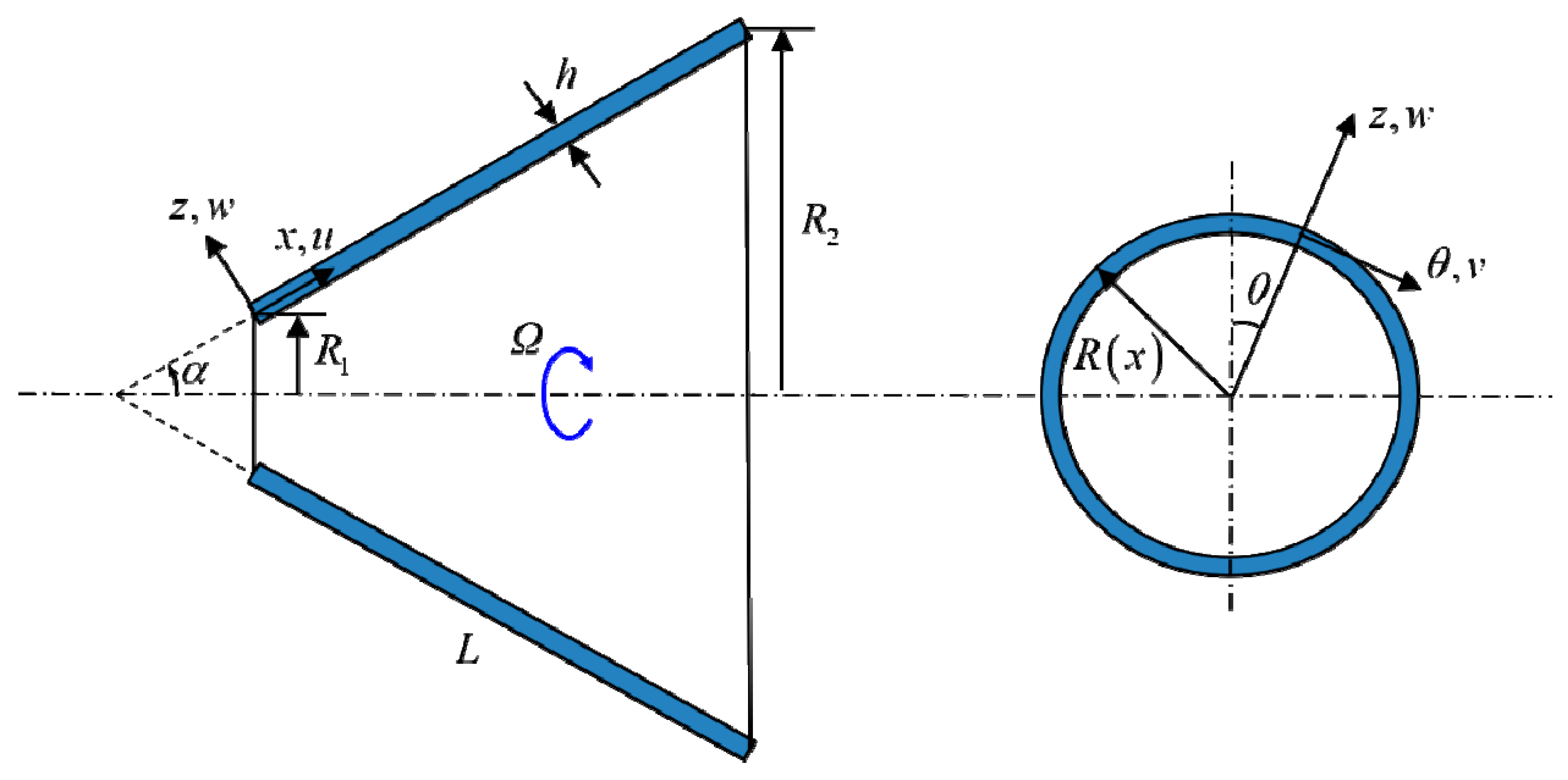
In Figure 1, a composite truncated conical shell that spins about its horizontal and symmetrical axis at a constant angular speed Ω is presented, where L, h, and α denote the length, thickness, and semivertex angle of the shell, respectively. An orthogonal coordinate system (x, θ, z) is fixed at the middle surface of the conical shell. The displacement components along the x, θ, and z directions are denoted by u(x, θ, z, t), v(x, θ, z, t), and w(x, θ, z, t), respectively. R1 and R2 in the figure refer to the mean radii at both ends, and the cone radius of any point in the x direction is expressed as R(x) = R1 + xsinα.
According to Love’s thin-shell theory [40], the strains of the conical shell in terms of the displacement components u(x, θ, z, t), v(x, θ, z, t) and w(x, θ, z, t) are expressed as follows:
where ε1, ε2, and γ represent the middle surface strains of the shell, and κ1, κ2, and χ are the middle surface curvatures. They are given as follows:
where R = R(x) is the cone radius of the middle surface.
Considering hygrothermal expansion deformation, the constitutive equation of a single-layer composite conical shell is given by:
where ε = (εx, εθ, εxθ)t and σ = (σx, σθ, σxθ)t represent total strain and stress vectors of the single-layer composite, the superscript t stands for transposition of the vectors. εT and εH refer to the thermal and humid strains, respectively, and is the stiffness matrix with the following elements [41]:
where θf represents fiber orientation angle defined as the angle from x-direction to the fiber orientation. In this study, fiber orientation lies symmetrically with respect to the midplane of the composite shell. Q11 = E1/(1 − v12v21), Q22 = E2/(1 − v12v21), Q12 = v21E2/(1 − v12v21), and Q66 = G12, in which E1, E2 are elastic moduli in principal orientation, G12 shear modulus, and v12, v21 Poisson ratios.
The thermal strain in Equation (3) generated by thermal expansion deformation is expressed as:
where . α12 = (α1, α2, 0)t, and α1, α2 are the thermal expansion coefficients along the principal orientation. ΔT is temperature variation, and Tt the transformation matrix given by the following form [41]:
The humid strain in Equation (3) caused by hygroscopic expansion deformation is given by:
where , β12 = (β1, β2, 0)t, and β1, β2 are the hygroscopic expansion coefficients. ΔC represents the moisture concentration, written as:
where M = Mf + Mm is the mass of composite material in dry condition, and ∆M = ∆Mf + ∆Mm the increment of mass in humid condition. Mf and Mm represent the mass of fiber and matrix, and ∆Mf and ∆Mm are the increment of mass of fiber and matrix.
Based on mechanics of composite materials [41], the in-surface force and moment resultants of the composite laminated truncated conical shell can be expressed as:
Substituting Equation (3) into Equation (9), the hygrothermal loads due to the hygrothermal expansion deformation can be obtained:
where (Hx, Hθ, Hxθ)t = εT + εH.
2.2. Governing Equations
The strain energy of spinning composite laminated truncated conical shells consists of two contributions, which correspond to strain energy UD generated by initial strains and strain energy Uh caused by spinning centrifugal force. They are formulated as follows:
In which denotes initial hoop tension due to the spinning centrifugal force, defined as:
where ρ is the density of the single-layer composite.
Considering spinning motion, the displacement vector r and the speed vector v at any point of the spinning conical shell take the form of:
In which i, j and k are the unit vectors along the x, θ, and z directions and .
Then, the kinetic energy of the spinning truncated conical shell in arbitrary time is expressed as:
where ρt is the density per unit area, described as:
For the sake of deriving governing equations of the spinning composite laminated truncated conical shell in a hygrothermal environment, Hamilton’s principle is utilized with the following form:
where W is the work performed by external loads and δW = 0 in this analysis.
Inserting Equations (11), (12) and (15) into Equation (17), the governing equations of the conical shell can be obtained:
where Lij (i, j = 1, 2, 3) are differential operators listed in Appendix A.
3. Solution Procedure
In this subsection, the Galerkin approach is utilized to derive the partial differential Equation (18). The displacement functions of the conical shells along the x, θ, and z directions are assumed as [42,43]:
where qmn(t), pmn(t) represent generalized displacement, and αmn and βmn are mode shape ratios [44]. φim(x)(I = u, v, w) represent the modal functions, m is the number of axial half waves, and n is the number of circumferential waves.
Considering a simply supported truncated conical shell, the boundary condition at both small and large edges (Ss–Sl) are expressed as:
Based on Equation (20), the corresponding modal functions of simply supported conical shells are defined as φu(x) = cos(λmx), φv(x) = φw(x) = sin(λmx), and λm = mπ/L.
Introducing Equation (19) into Equation (18) and multiplying mode shapes of Equation (19), respectively, integrating over the x-θ plane yields:
where I = 1, 2, …, mn. Mi represents mass coefficient of the conical shell for the i-th mode (m, n), Ci is damping coefficients generated by the Coriolis force owing to spinning motion, Ki is stiffness coefficient of the conical shell, and Kri is stiffness coefficient caused by spinning motion. They are listed in Appendix B.
For brevity, Equation (21) can be expressed as the following standard eigenvalue problem:
where
It is obvious that λ represents the characteristic root of Equation (22), which includes real and imaginary parts. The real part is three coupled roots corresponding to each combination of m and n of a specific truncated conical shell, related to natural frequencies of u, v, and w in each mode. Among them, the frequencies related to w are normally paid more attention because other frequencies are much higher than the ones for w. When the conical shell undergoes the spinning motion, the Coriolis force appears and induces the natural mode of the shell bifurcating into forward and backward traveling wave modes. Usually, the positive root related to w refers to natural frequency of a backward traveling wave, while the negative root represents the frequency of a forward traveling wave.
4. Results and Discussion
In this section, a detailed parametric study on free vibration characteristics of spinning composite laminated truncated conical shells in a hygrothermal environment is numerically performed. The graphite–epoxy composite laminated conical shell is adopted in the numerical simulation, and the variation in material properties of the composite shell with respect to temperature and moisture concentrations is presented in Table 1. A symmetric (θf/ − θf)s lay up of laminates is considered, and the density of the single-layer composite is 1600 kg/m3. ΔT in Equation (5) is defined as T − T0, and reference temperature T0 is assumed to be 25 °C. Unless otherwise specified, the fiber orientation angle θf = 60°, L/R1 = 5, and h/R1 = 0.01 obtain in the following.
It can be seen in Table 1 that elastic modulus E1 is unaffected by temperature or moisture concentration in a certain range. The reason is that the elastic modulus of graphite fiber, which has the predominant contribution in elastic modulus E1 of the conical shell, is much higher than that of the epoxy matrix, and the graphite fiber is negligibly affected by temperature and moisture. However, the epoxy matrix is the dominant influencing factor on elastic modulus E2 of the shell. It is highly susceptible to temperature variation and moisture concentration, and the influence of temperature on the matrix is more prominent than that of moisture. Moreover, elastic modulus G12 of the shell is related to both the graphite fiber and the epoxy matrix. Specifically, the graphite fiber and epoxy matrix are less affected by moisture, which demonstrates that G12 is unaffected by the moisture. However, the matrix is greatly affected by temperature, which indicates that G12 is reduced with the increase in temperature.
In what follows, the dimensionless values are introduced:
where ω*, ω1*, ω2*, and Ω* stand for dimensionless natural frequencies of the conical shell, frequencies of the forward traveling wave, frequencies of the backward traveling wave, and spinning angular speed, respectively.
4.1. Validation
In order to validate the accuracy of the present theory, the dimensionless natural frequencies of truncated conical shells with Ss–Sl boundary condition are compared with results in the literature, as listed in Table 2 and Table 3. Table 2 compares the frequency ω* of non-spinning conical shells for different semivertex angles. Table 3 compares the frequencies of forward and backward traveling waves of isotropic spinning conical shells, which correspond to ω1* and ω2*. It is observed that the present results agree well with those in the literature.
For the sake of demonstrating the validity of the present solution considering hygrothermal effects, the natural frequencies of composite truncated conical shells are calculated and compared with the results of the finite element method (FEM). In the modeling process, the quadrilateral shell elements with four nodes are used in Nastran software. The comparison results are presented in Table 4, where the relative error R = |ωFEM − ωpresent|/ωFEM and spinning speed are ignored. It is shown that the difference between the FEM results and the present results is very slight, and the maximum error is less than 0.83%, which validates the validity of the present solution.
4.2. Natural Frequency and Critical Spinning Angular Speed
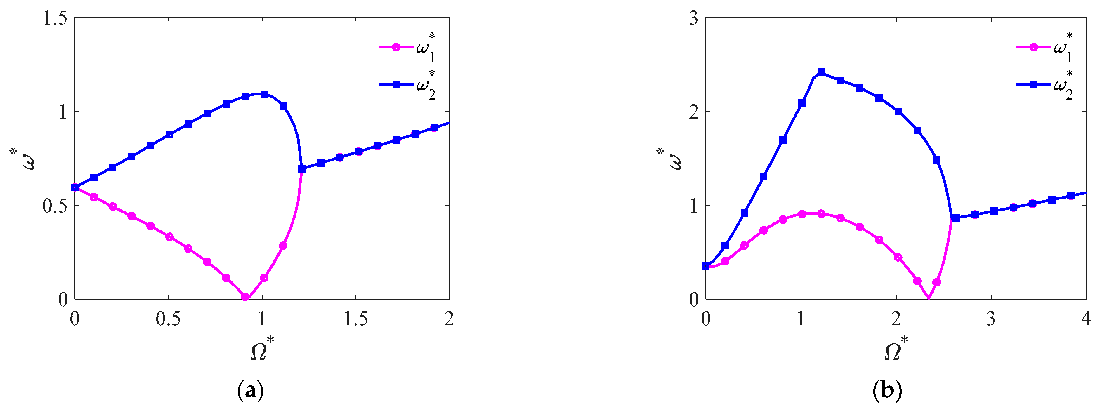
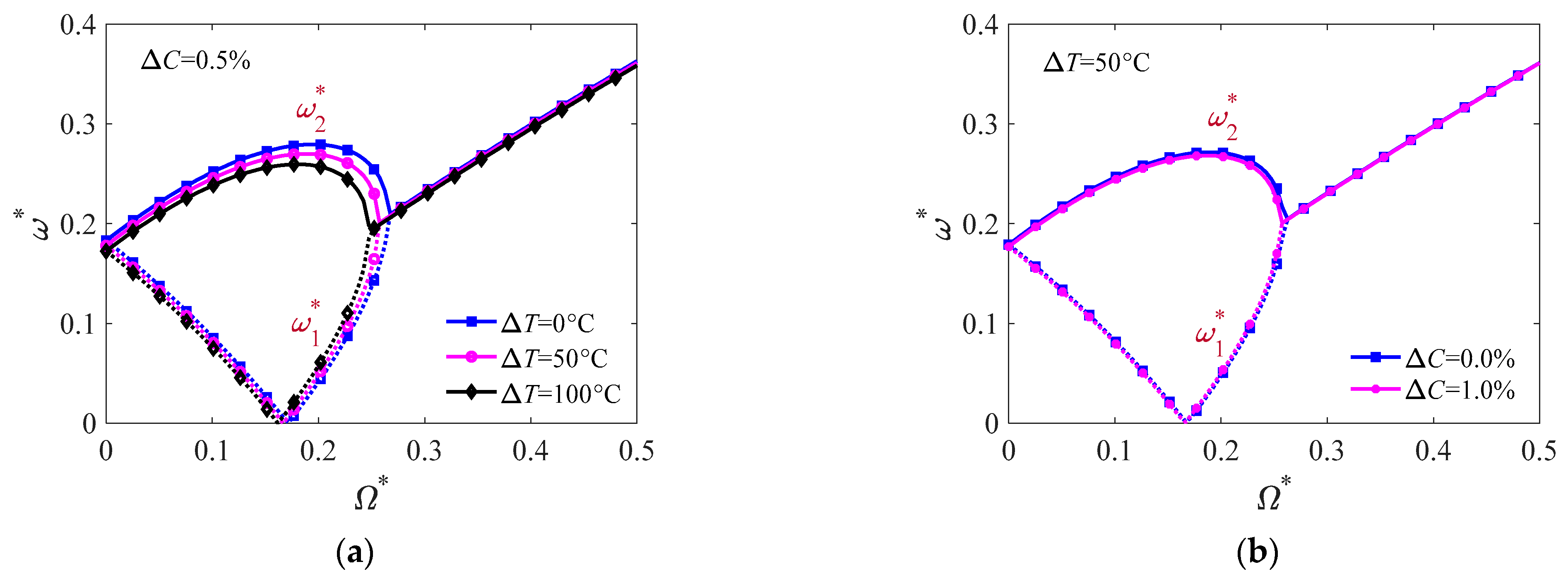
In this subsection, natural frequency and critical spinning speed of composite laminated spinning truncated conical shells in a hygrothermal environment are studied. Figure 2 displays the change in dimensionless natural frequencies against spinning angular speed Ω* for modes (m, n) = (1, 1–4). One can find a bifurcation of the frequencies when the speed Ω* exists, where ω1* and ω2* represent the frequencies of forward and backward traveling waves, respectively. For mode (1, 1), ω1* descends monotonically with Ω* until the one intersects the abscissa, and then ascends again. The value of the corresponding abscissa is critical spinning angular speed Ωc*, which means a potential divergent instability. While ω2* ascends with Ω* before the instability occurs, after that ω2* descends until it coincides with ω1*. This phenomenon is attributed to the spin-induced Coriolis and centrifugal forces, which both affect the stiffness of the conical shells. In a physical sense, the Coriolis force induces the asymmetric influence on natural frequencies of forward and backward traveling waves, which weakens the frequency of the forward traveling wave and enlarges the frequency of the backward traveling wave. However, centrifugal force stiffens the shells and enhances the frequencies of both traveling waves symmetrically. In the lower spinning angular speed region (before critical spinning angular speed), the Coriolis force has the dominant contribution in the frequencies and leads to different trends of forward and backward traveling waves. After that, centrifugal force has the more significant effect on the frequencies in the higher angular speed region, which causes the increase in frequencies of both traveling waves.
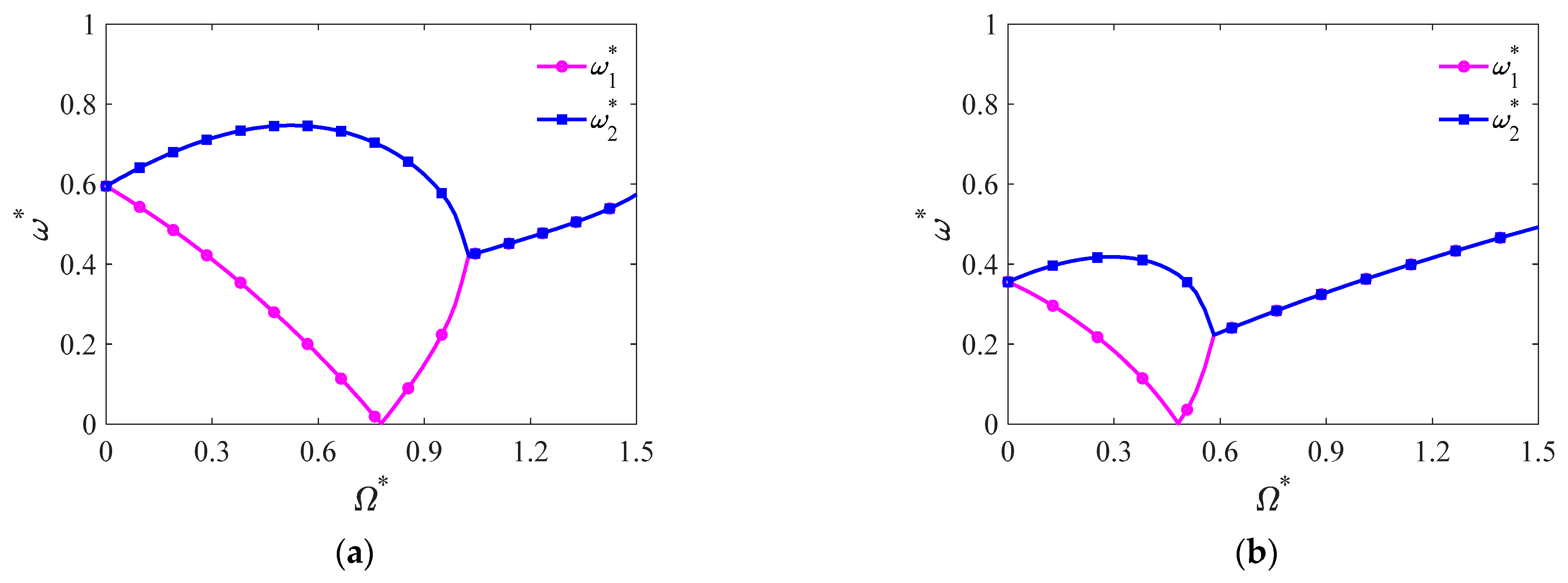
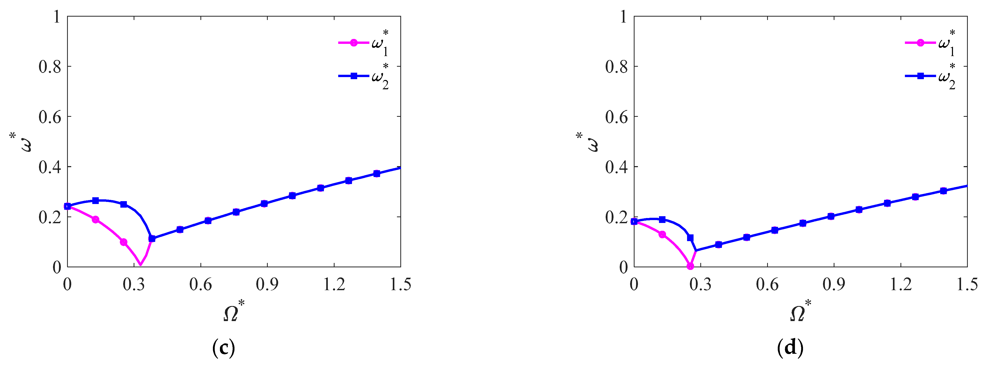
For modes (1, 2–4), it is found that with the increase of Ω*, ω1* initially ascends and then descends until critical spinning speed Ωc* appears. It can be inferred that the initial hoop tension generated by the spinning centrifugal effect results in the difference, as shown in Equation (13). Figure 3 plots the variation of the frequencies against spinning speed for modes (1, 1–4), where initial hoop tension is ignored. It is clearly seen that for modes (1, 2–4), the variation trend of ω1* against Ω* becomes similar with the mode ones (1, 1). It is also found that the values of critical spinning speed are reduced obviously compared with the case in Figure 2b–d, considering initial hoop tension. However, the critical speed of mode (1, 1) only has a slight decrease compared with that in the presence of initial hoop tension. From Figure 2 and Figure 3, one can obtain the conclusion that the initial hoop tension is the predominant factor resulting in the increase of critical spinning speed for higher modes.
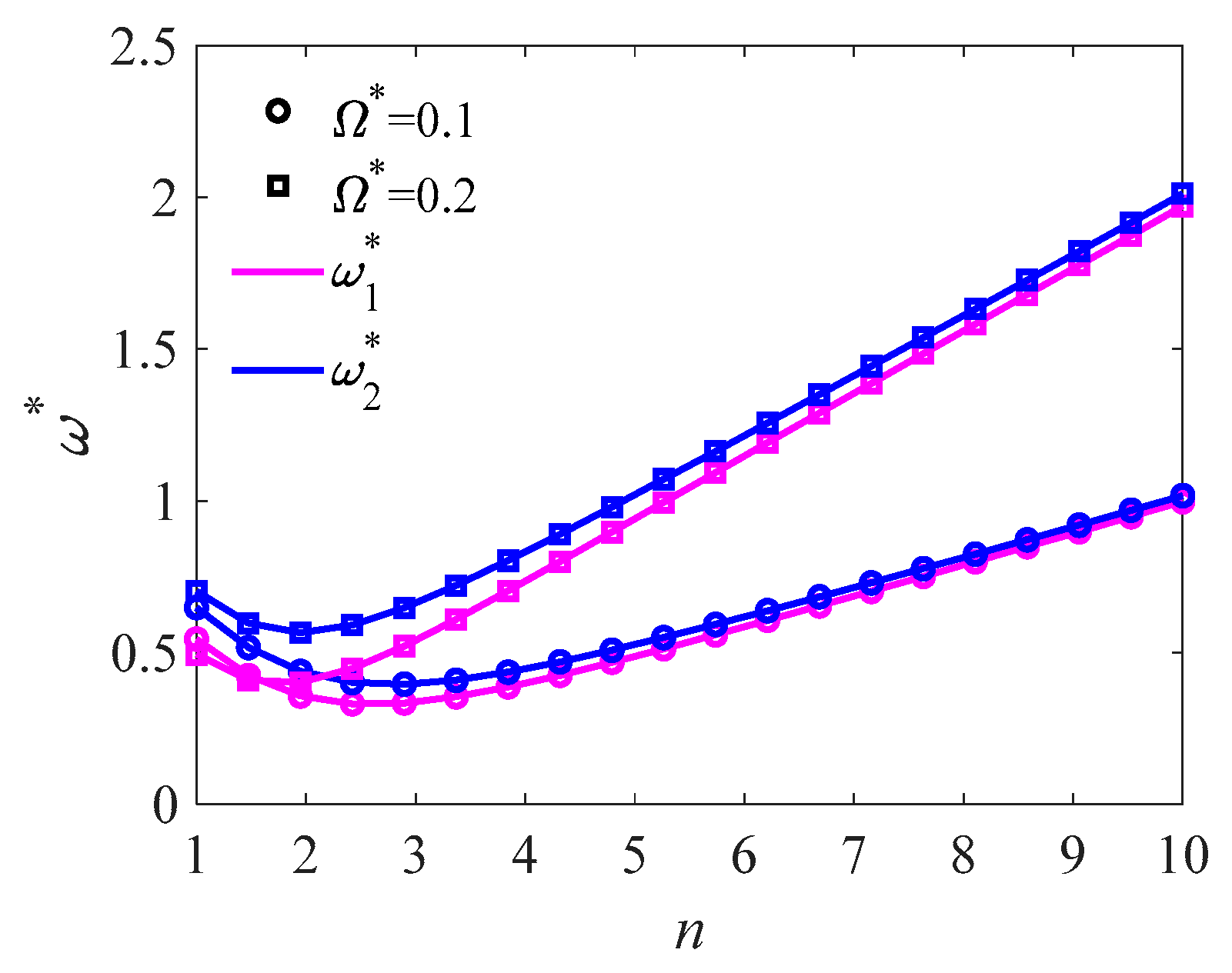
In Figure 4, the variation of dimensionless natural frequencies against number of circumferential waves for various spinning angular speeds is displayed. It is seen that the frequencies of forward and backward traveling waves firstly descend and then ascend with number of circumferential waves n, which illustrates that the frequency of mode (1, 1) is not the smallest among all vibration modes of the conical shells. It is also shown that the frequencies of both traveling waves with higher angular speed are more affected by circumferential wave number than those with lower speed.
4.3. Hygrothermal Analysis
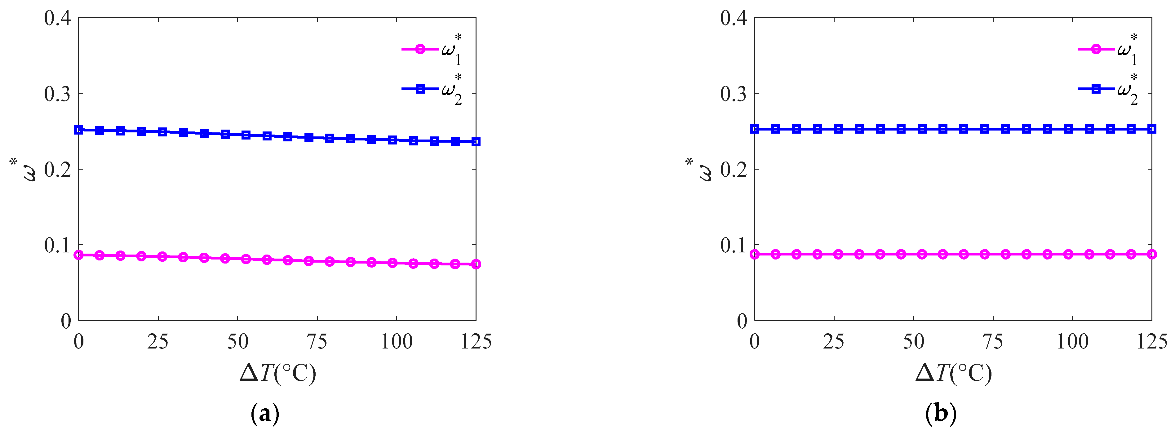
In this section, hygrothermal analysis on vibration characteristics of the conical shells is carried out. Figure 5 presents the effects of temperature variation and moisture concentration on natural frequencies of forward and backward traveling waves, respectively. It is manifest in Figure 5a that the frequencies of both traveling waves all descend with temperature variation ΔT, which is because the increase in temperature would weaken the stiffness of the shell. As a general reality, temperature variation can induce thermal expansion deformation and changes in material properties of the composite. In Figure 6, the effects of thermal expansion deformation and material property variation on the frequencies of both traveling waves are plotted. It can be observed that when the same temperature variation happens, the frequencies decrease with ΔT only considering thermal expansion deformation (as shown in Figure 6a), while the ones are little affected by ΔT considering solely material property variation (as shown in Figure 6b). It can be concluded that the thermal expansion deformation is nonnegligible in free vibration analysis of the spinning composite laminated truncated conical shells.
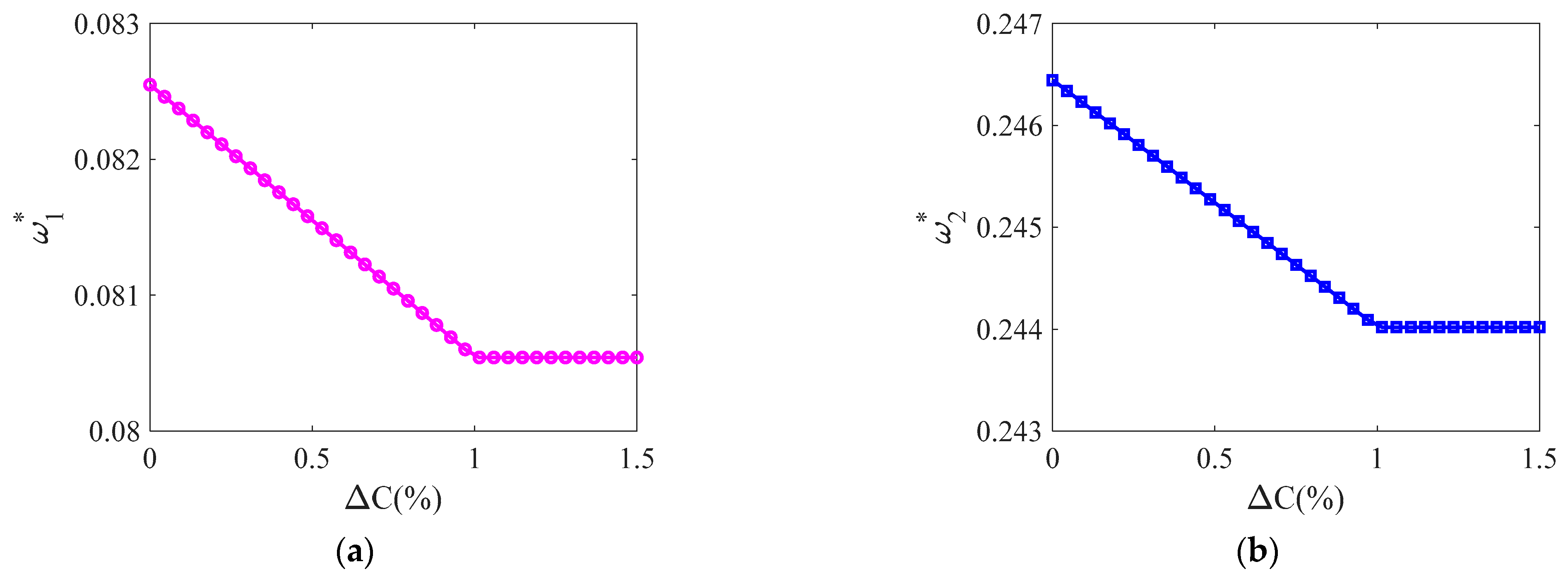
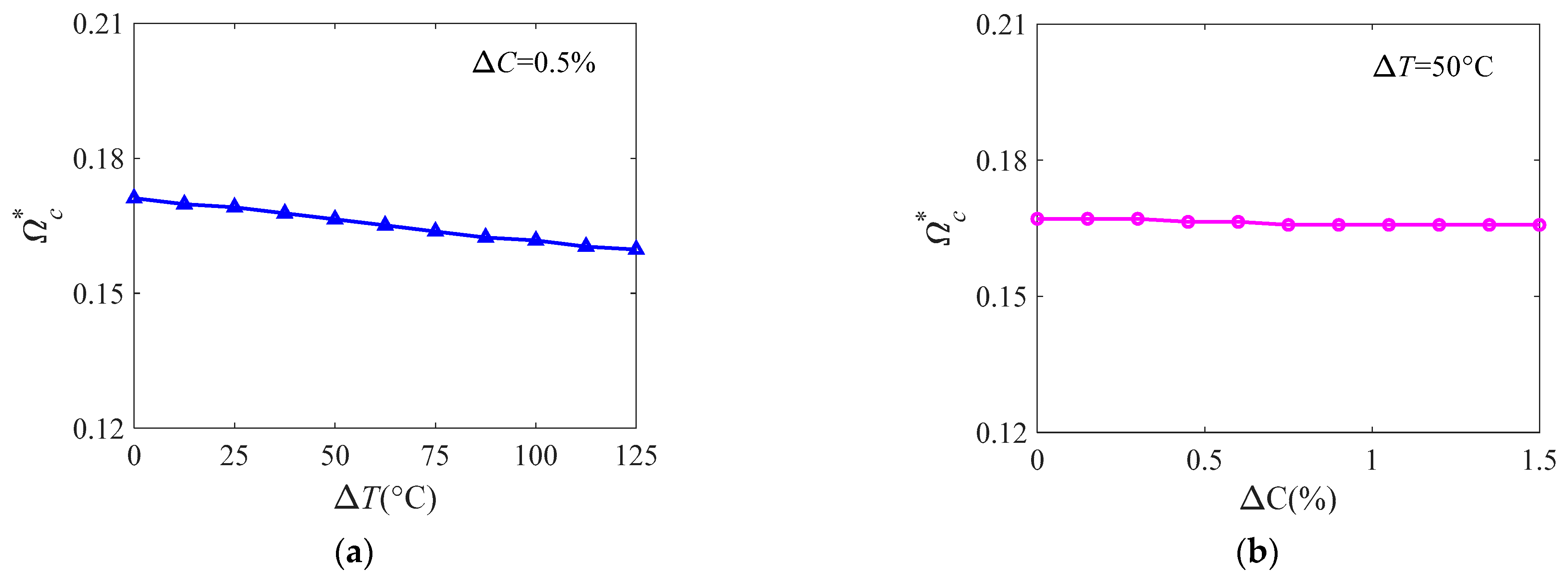
From Figure 5b, it is indicated that the frequencies of both traveling waves decrease slightly with moisture concentration ΔC, which is attributed to hygroscopic expansion deformation and the reduction of elastic modulus E2. Figure 7 displays the variation in dimensionless natural frequencies against ΔC. The variation is similar with the variation trend of E2 in Table 1 against ΔC, which reveals that the elastic modulus E2 is the dominant factor in the frequencies of the shell, rather than the hygroscopic expansion deformation. Figure 8, which plots the effects of temperature variation and moisture concentration on critical spinning angular speed, respectively, demonstrates that temperature and moisture both impair the critical spinning speed of the shells, but temperature has more effect on the reduction of critical speed than moisture. Results in Figure 5, Figure 6, Figure 7 and Figure 8 reveal that the influence of moisture concentration on the frequencies and critical spinning speed of the shell are less prominent than that of temperature.
4.4. Effects of Design Parameters on Vibration Characteristics
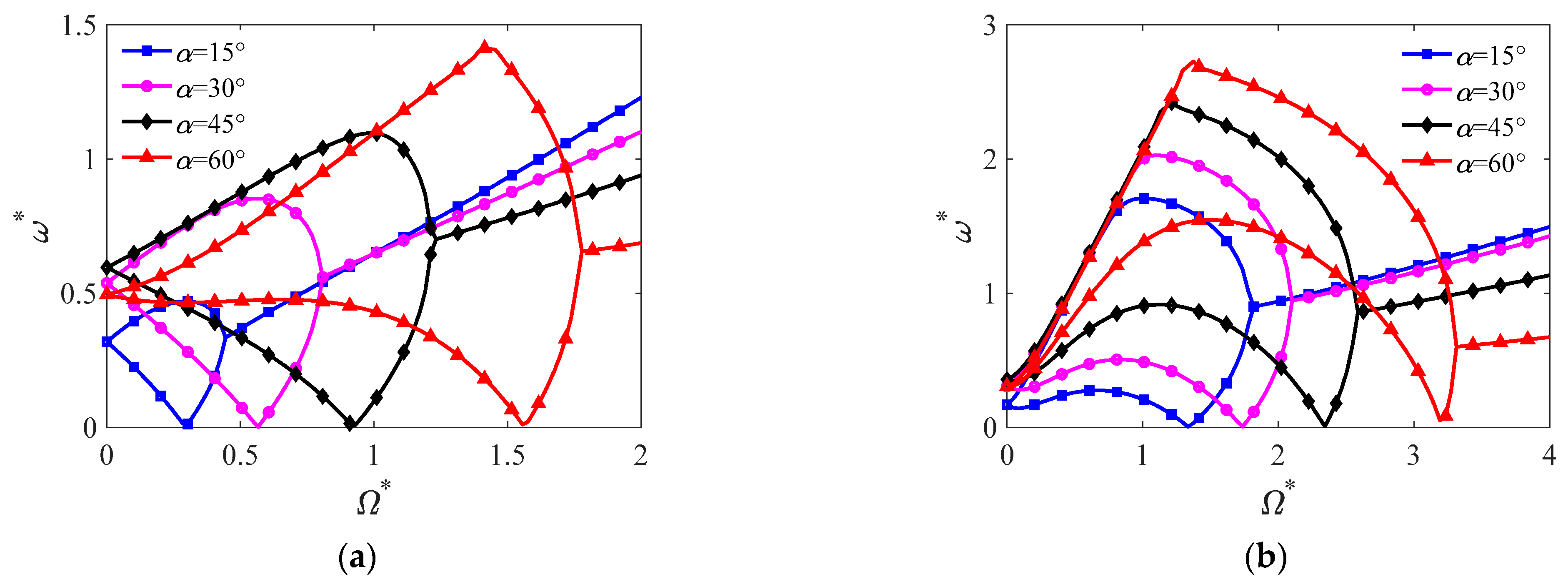
In this section, the effects of design parameters on vibration characteristics are presented, including semivertex angle and fiber orientation angle. Figure 9 plots the influence of semivertex angle on dimensionless natural frequencies and critical spinning speed. One can see that the frequencies of forward and backward traveling waves vary obviously with semivertex angle α, and the critical spinning speed is reduced with α. It is a fact that the influence of the semivertex angle on the frequencies of both traveling waves depends on the vibration modes. In Figure 10, the variation in frequencies against semivertex angle for various circumferential wave numbers is presented. It is seen that the frequencies of both traveling waves initially increase and then decrease with α for all vibration modes, but the frequencies are more sensitive to the lower-order modes than the higher ones.
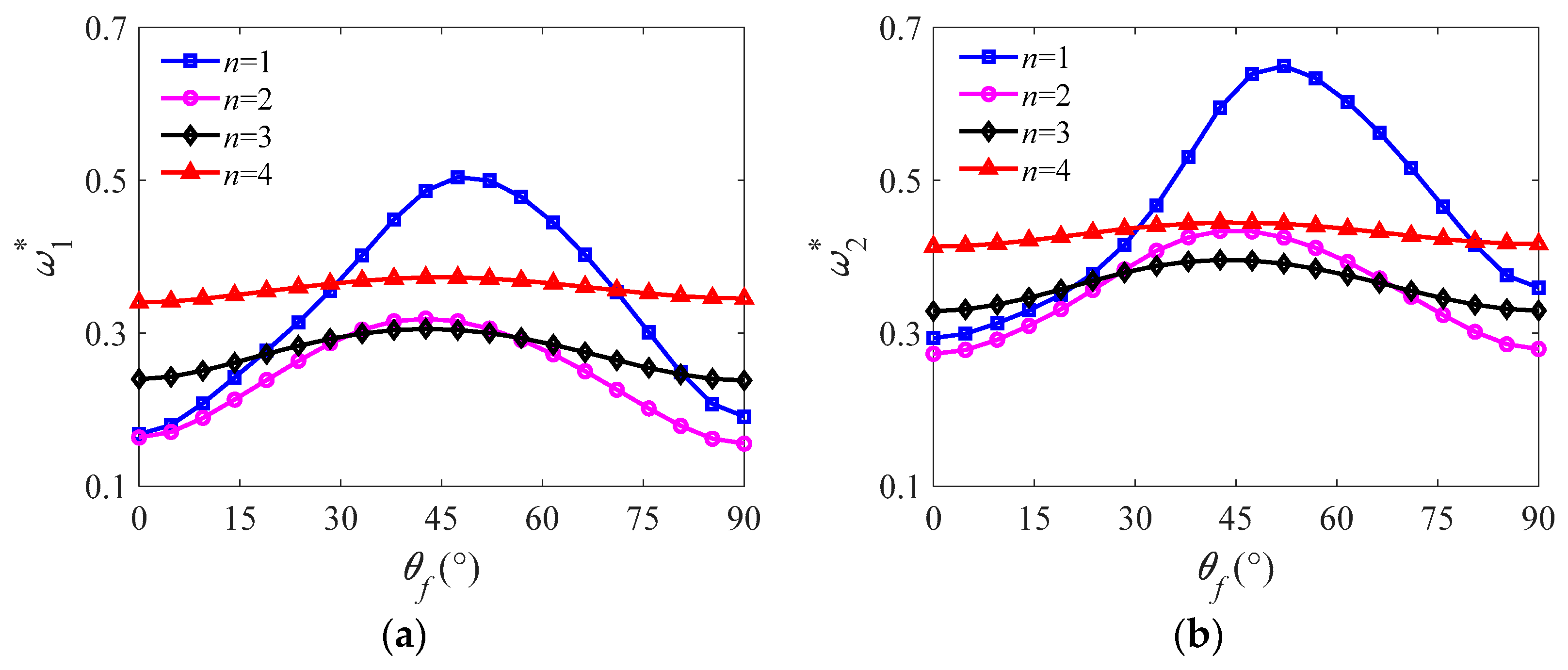
In Figure 11, the variation in dimensionless natural frequencies of forward and backward traveling waves against fiber orientation angle θf is presented, where θf represents (θf/ − θf)s layup of laminate. It is seen that both frequencies firstly ascend and then descend with θf for all vibration modes, but the variation in frequencies of lower-order modes is more significant than the ones of higher modes. In a physical sense, lamination schemes of composites would affect the stiffness of the conical shells, which leads to the variation of the frequencies. In Figure 9, Figure 10 and Figure 11, we can see that the dynamic behavior of spinning composite truncated conical shells can be distinctly controlled by employing suitable values of design parameters.
5. Conclusions
Free vibration characteristics of a spinning composite laminated truncated conical shell subjected to hygrothermal environment were examined in the present work. The governing equations of the free vibration of the conical shell were established based on Love’s thin-shell theory and Hamilton’s principle. The Galerkin approach was used to derive the free vibration characteristics of the conical shell. The combined effects of spinning angular speed, temperature, moisture concentration, semivertex angle, and fiber orientation angle on natural frequencies and critical spinning speeds were studied systematically. The conclusions are as follows:
- The Coriolis force is the dominant factor resulting in the asymmetric variation of natural frequencies of forward and backward traveling waves. The centrifugal force would stiffen the conical shell and enhance the frequencies of both traveling waves symmetrically, and initial hoop tension plays a major role in the increase of critical spinning angular speed.
- Temperature and moisture concentration both weaken natural frequencies and critical spinning speeds of the shell, and the influence of temperature on the frequencies and the speed is more prominent than that of moisture concentration. In addition, thermal expansion deformation is nonnegligible in free vibration analysis of spinning composite laminated truncated conical shells.
- Natural frequencies of forward and backward traveling waves all initially increase and then decrease with semivertex angle and fiber orientation angle, which indicates that vibration behavior of the conical shell can be distinctly controlled by using suitable values of design parameters.
Author Contributions
Conceptualization, X.L. and Z.Z.; methodology, X.L.; validation, X.L. and Z.Z.; data curation, X.L., X.Z. and Z.Z.; writing—original draft preparation, X.L.; writing—review and editing, X.L. and Z.Z.; supervision, Z.Z.; funding acquisition, X.L. All authors have read and agreed to the published version of the manuscript.
Funding
This research was funded by the Key Laboratory of Icing and Anti/De-icing of CARDC (grant no. IADL20210201) and the National Natural Science Foundation of China (grant no. 12002225).
Institutional Review Board Statement
Not applicable.
Informed Consent Statement
Not applicable.
Data Availability Statement
The data presented in this study are available from the corresponding author upon reasonable request.
Conflicts of Interest
On behalf of all authors, the corresponding author states that there are no conflicts of interest.
Appendix A
Appendix B
The mass: damping and stiffness coefficients in Equation (21) are expressed as:
where
of which
The stiffness coefficients Kri in Equation (21) are expressed as:
in which
The primes in Equations (A11)–(A13) refer to differentiation with respect to the variable x.
References
- Sun, S.P.; Liu, L.; Cao, D.Q. Nonlinear travelling wave vibrations of a rotating thin cylindrical shell. J. Sound Vib. 2018, 431, 122–136. [Google Scholar] [CrossRef]
- Gibson, R.F. A review of recent research on mechanics of multifunctional composite materials and structures. Compos. Struct. 2010, 92, 2793–2810. [Google Scholar] [CrossRef]
- Bryan, G.H. On the beats in the vibrations of a revolving cylinder or bell. Proc. Camb. Philos. Soc. 1890, 7, 101–111. [Google Scholar]
- Srinivasan, A.; Lauterbach, G.F. Traveling waves in rotating cylindrical shells. J. Eng. Ind. 1971, 93, 1229–1232. [Google Scholar] [CrossRef]
- Li, H. Frequency characteristics of a rotating truncated circular layered conical shell. Compos. Struct. 2000, 50, 59–68. [Google Scholar]
- Lam, K.Y.; Li, H. Influence of boundary conditions on the frequency characteristics of a rotating truncated circular conical shell. J. Sound Vib. 1999, 223, 171–195. [Google Scholar] [CrossRef]
- Ng, T.Y.; Li, H.; Lam, K.Y. Generalized differential quadrature for free vibration of rotating composite laminated conical shell with various boundary conditions. Int. J. Mech. Sci. 2003, 45, 567–587. [Google Scholar] [CrossRef]
- Li, X.; Li, Y.H.; Xie, T.F. Vibration characteristics of a rotating composite laminated cylindrical shell in subsonic air flow and hygrothermal environment. Int. J. Mech. Sci. 2019, 150, 356–368. [Google Scholar] [CrossRef]
- Talebitooti, M.; Ghayour, M.; Ziaei-Rad, S.; Talebitooti, R. Free vibrations of rotating composite conical shells with stringer and ring stiffeners. Arch. Appl. Mech. 2009, 80, 201–215. [Google Scholar] [CrossRef]
- Liew, K.M.; Ng, T.Y.; Zhao, X. Free vibration analysis of conical shells via the element-free kp-Ritz method. J. Sound Vib. 2005, 281, 627–645. [Google Scholar] [CrossRef]
- Sivadas, K. Vibration analysis of pre-stressed rotating thick circular conical shell. J. Sound Vib. 1995, 186, 99–109. [Google Scholar] [CrossRef]
- Chen, C.; Dai, L. Nonlinear vibration and stability of a rotary truncated conical shell with intercoupling of high and low order modals. Commun. Nonlinear Sci. Numer. Simul. 2009, 14, 254–269. [Google Scholar] [CrossRef]
- Wu, C.P.; Chiu, S.J. Thermally induced dynamic instability of laminated composite conical shells. Int. J. Solids Struct. 2002, 39, 3001–3021. [Google Scholar] [CrossRef]
- Dong, Y.; Li, X.; Gao, K.; Li, Y.; Yang, J. Harmonic resonances of graphene-reinforced nonlinear cylindrical shells: Effects of spinning motion and thermal environment. Nonlinear Dyn. 2020, 99, 981–1000. [Google Scholar] [CrossRef]
- Sun, S.; Cao, D.; Han, Q. Vibration studies of rotating cylindrical shells with arbitrary edges using characteristic orthogonal polynomials in the Rayleigh–Ritz method. Int. J. Mech. Sci. 2013, 68, 180–189. [Google Scholar] [CrossRef]
- Li, X.; Xu, Q.; Li, Y.H. Parametric Instability of a Rotating Axially Loaded FG Cylindrical Thin Shell Under Both Axial Disturbances and Thermal Effects. Z. Nat. A 2018, 73, 1105–1119. [Google Scholar] [CrossRef]
- Li, X.; Du, C.C.; Li, Y.H. Parametric resonance of a FG cylindrical thin shell with periodic rotating angular speeds in thermal environment. Appl. Math. Model. 2018, 59, 393–409. [Google Scholar] [CrossRef]
- Zhang, W.; Niu, Y.; Behdinan, K. Vibration characteristics of rotating pretwisted composite tapered blade with graphene coating layers. Aerosp. Sci. Technol. 2020, 98, 105644. [Google Scholar] [CrossRef]
- Wang, Y.; Wu, D. Free vibration of functionally graded porous cylindrical shell using a sinusoidal shear deformation theory. Aerosp. Sci. Technol. 2017, 66, 83–91. [Google Scholar] [CrossRef]
- Sheikh, A.H.; Asadi, A.; Thomsen, O.T. Vibration of thin-walled laminated composite beams having open and closed sections. Compos. Struct. 2015, 134, 209–215. [Google Scholar] [CrossRef]
- Chen, X.; Chen, L.; Huang, S.; Li, M.; Li, X. Nonlinear forced vibration of in-plane bi-directional functionally graded materials rectangular plate with global and localized geometrical imperfections. Appl. Math. Model. 2021, 93, 443–466. [Google Scholar] [CrossRef]
- Cuong-Le, T.; Nguyen, K.D.; Hoang-Le, M.; Sang-To, T.; Phan-Vu, P.; Wahab, M.A. Nonlocal strain gradient IGA numerical solution for static bending, free vibration and buckling of sigmoid FG sandwich nanoplate. Phys. B Condens. Matter 2022, 631, 413726. [Google Scholar] [CrossRef]
- Cuong-Le, T.; Nguyen, K.D.; Lee, J.; Rabczuk, T.; Nguyen-Xuan, H. A 3D nano scale IGA for free vibration and buckling analyses of multi-directional FGM nanoshells. Nanotechnology 2021, 33, 065703. [Google Scholar] [CrossRef] [PubMed]
- Li, X.; Jiang, W.; Chen, X.; Zhou, Z. Nonlinear forced vibration of rotating composite laminated cylindrical shells under hygrothermal environment. Z. Nat. A 2021, 76, 769–786. [Google Scholar] [CrossRef]
- Shakouri, M. Free vibration analysis of functionally graded rotating conical shells in thermal environment. Compos. Part B Eng. 2019, 163, 574–584. [Google Scholar] [CrossRef]
- Civalek, Ö. Discrete singular convolution method for the free vibration analysis of rotating shells with different material properties. Compos. Struct. 2017, 160, 267–279. [Google Scholar] [CrossRef]
- Heydarpour, Y.; Aghdam, M.M.; Malekzadeh, P. Free vibration analysis of rotating functionally graded carbon nanotube-reinforced composite truncated conical shells. Compos. Struct. 2014, 117, 187–200. [Google Scholar] [CrossRef]
- Li, X.; Chen, X.C.; Jiang, W.T. Dynamic stability of graded graphene reinforced truncated conical shells under both periodic spinning speeds and axial loads considering thermal effects. Eng. Struct. 2022, 256, 113963. [Google Scholar] [CrossRef]
- Heydarpour, Y.; Malekzadeh, P.; Aghdam, M.M. Free vibration of functionally graded truncated conical shells under internal pressure. Meccanica 2013, 49, 267–282. [Google Scholar] [CrossRef]
- Zhao, X.; Li, Y. Vibration and Acoustic Responses of an Orthotropic Composite Conical Shell in a Hygroscopic Environment. Int. J. Appl. Mech. 2015, 7, 1550053. [Google Scholar] [CrossRef]
- Shen, H.S.; Xiang, Y. Thermal buckling and postbuckling behavior of FG-GRC laminated cylindrical shells with temperature-dependent material properties. Meccanica 2019, 54, 283–297. [Google Scholar] [CrossRef]
- Patel, B.; Ganapathi, M.; Makhecha, D. Hygrothermal effects on the structural behaviour of thick composite laminates using higher-order theory. Compos. Struct. 2002, 56, 25–34. [Google Scholar] [CrossRef]
- Biswal, M.; Sahu, S.K.; Asha, A.V. Vibration of composite cylindrical shallow shells subjected to hygrothermal loading-experimental and numerical results. Compos. Part B Eng. 2016, 98, 108–119. [Google Scholar] [CrossRef]
- Li, X. Parametric resonances of rotating composite laminated nonlinear cylindrical shells under periodic axial loads and hygrothermal environment. Compos. Struct. 2021, 255, 112887. [Google Scholar] [CrossRef]
- Qin, Y.; Li, X.; Yang, E.C.; Li, Y.H. Flapwise free vibration characteristics of a rotating composite thin-walled beam under aerodynamic force and hygrothermal environment. Compos. Struct. 2016, 153, 490–503. [Google Scholar] [CrossRef]
- Qin, Y.; Li, Y.H. Influences of hygrothermal environment and installation mode on vibration characteristics of a rotating laminated composite beam. Mech. Syst. Signal Process. 2017, 91, 23–40. [Google Scholar] [CrossRef]
- Bandyopadhyay, T.; Karmakar, A.; Kishimoto, K. Transient response of delaminated composite conical shells due to multiple low velocity impacts in hygrothermal environment. Compos. Struct. 2016, 143, 202–219. [Google Scholar] [CrossRef]
- Hajmohammad, M.H.; Azizkhani, M.B.; Kolahchi, R. Multiphase nanocomposite viscoelastic laminated conical shells subjected to magneto-hygrothermal loads: Dynamic buckling analysis. Int. J. Mech. Sci. 2018, 137, 205–213. [Google Scholar] [CrossRef]
- Parhi, A.; Singh, B.N.; Panda, S.K. Nonlinear free vibration analysis of composite conical shell panel with cluster of delamination in hygrothermal environment. Eng. Comput. 2019, 37, 1565–1577. [Google Scholar] [CrossRef]
- Love, A.E.H. A Treatise on the Mathematical Theory of Elasticity; Cambridge University Press: New York, NY, USA, 2013; Volume 1. [Google Scholar]
- Jones, R.M. Mechanics of Composite Materials; Scripta Book Company: Washington, DC, USA, 1975; Volume 193. [Google Scholar]
- Huang, S.; Hsu, B. Resonant phenomena of a rotating cylindrical shell subjected to a harmonic moving load. J. Sound Vib. 1990, 136, 215–228. [Google Scholar] [CrossRef]
- Wang, Y.Q. Nonlinear vibration of a rotating laminated composite circular cylindrical shell: Traveling wave vibration. Nonlinear Dyn. 2014, 77, 1693–1707. [Google Scholar] [CrossRef]
- Soedel, W. Vibrations of Shells and Plates; Marcel Dekker Incorporated: New York, NY, USA, 1981. [Google Scholar]
- Han, Q.K.; Chu, F.L. Parametric resonance of truncated conical shells rotating at periodically varying angular speed. J. Sound Vib. 2014, 333, 2866–2884. [Google Scholar] [CrossRef]
Figure 1.
Spinning truncated conical shell configuration.

Figure 2.
Variation in dimensionless natural frequencies against spinning angular speed (α = 45°, ΔT = 50 °C, ΔC = 1.0%). (a) mode (1, 1); (b) mode (1, 2); (c) mode (1, 3); (d) mode (1, 4).
Figure 2.
Variation in dimensionless natural frequencies against spinning angular speed (α = 45°, ΔT = 50 °C, ΔC = 1.0%). (a) mode (1, 1); (b) mode (1, 2); (c) mode (1, 3); (d) mode (1, 4).


Figure 3.
Variation of dimensionless natural frequencies against spinning angular speed without considering initial hoop tension (α = 45°, ΔT = 50 °C, ΔC = 1.0%). (a) mode (1, 1); (b) mode (1, 2); (c) mode (1, 3); (d) mode (1, 4).
Figure 3.
Variation of dimensionless natural frequencies against spinning angular speed without considering initial hoop tension (α = 45°, ΔT = 50 °C, ΔC = 1.0%). (a) mode (1, 1); (b) mode (1, 2); (c) mode (1, 3); (d) mode (1, 4).


Figure 4.
Variation of dimensionless natural frequencies against number of circumferential waves for different spinning angular speeds (m = 1, α = 45°, ΔT = 50 °C, ΔC = 1.0%).
Figure 4.
Variation of dimensionless natural frequencies against number of circumferential waves for different spinning angular speeds (m = 1, α = 45°, ΔT = 50 °C, ΔC = 1.0%).

Figure 5.
Effects of (a) temperature variation and (b) moisture concentration on dimensionless natural frequencies of mode (1, 1) (α = 7.5°).
Figure 5.
Effects of (a) temperature variation and (b) moisture concentration on dimensionless natural frequencies of mode (1, 1) (α = 7.5°).

Figure 6.
Effects of (a) thermal expansion deformation and (b) material property variation generated by temperature on dimensionless natural frequencies of mode (1, 1) (Ω* = 0.1, α = 7.5°).
Figure 6.
Effects of (a) thermal expansion deformation and (b) material property variation generated by temperature on dimensionless natural frequencies of mode (1, 1) (Ω* = 0.1, α = 7.5°).

Figure 7.
Variation in dimensionless natural frequencies of mode (1, 1) against moisture concentration (Ω* = 0.1, α = 7.5°). (a) Natural frequency of forward traveling wave; (b) natural frequency of backward traveling wave.
Figure 7.
Variation in dimensionless natural frequencies of mode (1, 1) against moisture concentration (Ω* = 0.1, α = 7.5°). (a) Natural frequency of forward traveling wave; (b) natural frequency of backward traveling wave.

Figure 8.
Effects of (a) temperature variation and (b) moisture concentration on critical spinning angular speed of mode (1, 1) (α = 7.5°).
Figure 8.
Effects of (a) temperature variation and (b) moisture concentration on critical spinning angular speed of mode (1, 1) (α = 7.5°).

Figure 9.
Effect of semivertex angle on dimensionless natural frequencies (ΔT = 50 °C, ΔC = 0.5%). (a) Mode (1, 1); (b) mode (1, 2).
Figure 9.
Effect of semivertex angle on dimensionless natural frequencies (ΔT = 50 °C, ΔC = 0.5%). (a) Mode (1, 1); (b) mode (1, 2).

Figure 10.
Variation in dimensionless natural frequencies against semivertex angle (Ω* = 0.1, ΔT = 50 °C, ΔC = 0.5%). (a) Natural frequency of forward traveling wave; (b) natural frequency of backward traveling wave.
Figure 10.
Variation in dimensionless natural frequencies against semivertex angle (Ω* = 0.1, ΔT = 50 °C, ΔC = 0.5%). (a) Natural frequency of forward traveling wave; (b) natural frequency of backward traveling wave.

Figure 11.
Variation in dimensionless natural frequencies against fiber orientation angle (Ω* = 0.1, ΔT = 50 °C, ΔC = 0.5%). (a) Natural frequency of forward traveling wave; (b) natural frequency of backward traveling wave.
Figure 11.
Variation in dimensionless natural frequencies against fiber orientation angle (Ω* = 0.1, ΔT = 50 °C, ΔC = 0.5%). (a) Natural frequency of forward traveling wave; (b) natural frequency of backward traveling wave.


Table 1.
Variation of elastic modulus of graphite–epoxy laminate [32].
Table 1.
Variation of elastic modulus of graphite–epoxy laminate [32].
| Modulus (GPa) | (a) Moisture Concentration, ΔC (%) | ||||||
|---|---|---|---|---|---|---|---|
| 0.00 | 0.25 | 0.50 | 0.75 | 1.00 | 1.25 | 1.50 | |
| E1 | 130 | 130 | 130 | 130 | 130 | 130 | 130 |
| E2 | 9.5 | 9.25 | 9.0 | 8.75 | 8.5 | 8.5 | 8.5 |
| G12 | 6.0 | 6.0 | 6.0 | 6.0 | 6.0 | 6.0 | 6.0 |
| (b) Temperature, T (°C) | |||||||
| 25 | 50 | 75 | 100 | 125 | 150 | ||
| E1 | 130 | 130 | 130 | 130 | 130 | 130 | |
| E2 | 9.5 | 8.5 | 8.0 | 7.5 | 7.0 | 6.75 | |
| G12 | 6.0 | 6.0 | 5.5 | 5.0 | 4.75 | 4.5 | |
(a) At different moisture concentrations: G13 = G12, G23 = 0.5G12, ν12 = 0.3, β1 = 0, β2 = 0.44 × 10⁻⁶; (b) at different temperatures: G13 = G12, G23 = 0.5 G12, ν12 = 0.3, α1 = −0.3 × 10⁻⁶/°C, α2 = 28.1 × 10⁻⁶/°C.
Table 2.
Comparison of dimensionless natural frequencies for Ss–Sl non-spinning truncated conical shells (m = 1, h/R1 = 0.01, Lsinα/R2 = 0.25, ν = 0.3).
Table 2.
Comparison of dimensionless natural frequencies for Ss–Sl non-spinning truncated conical shells (m = 1, h/R1 = 0.01, Lsinα/R2 = 0.25, ν = 0.3).
| n | α = 30° | α = 60° | ||
|---|---|---|---|---|
| Reference [10] | Present | Reference [10] | Present | |
| 2 | 0.7909 | 0.8078 | 0.5719 | 0.5893 |
| 3 | 0.7281 | 0.7314 | 0.5998 | 0.6022 |
| 4 | 0.6347 | 0.6261 | 0.6049 | 0.6139 |
| 5 | 0.5522 | 0.5359 | 0.6071 | 0.6186 |
Table 3.
Comparison of dimensionless natural frequencies for Ss–Sl isotropic spinning truncated conical shells (m = 1, h/R1 = 0.1, L/R1 = 6, α = 30°, ν = 0.3).
Table 3.
Comparison of dimensionless natural frequencies for Ss–Sl isotropic spinning truncated conical shells (m = 1, h/R1 = 0.1, L/R1 = 6, α = 30°, ν = 0.3).
| Ω* | n | Reference [45] | Reference [6] | Present | |||
|---|---|---|---|---|---|---|---|
| 0 | 1 | 0.7414 | 0.7414 | 0.7414 | 0.7414 | 0.7454 | 0.7454 |
| 2 | 0.4456 | 0.4456 | 0.4456 | 0.4456 | 0.4481 | 0.4481 | |
| 3 | 0.2785 | 0.2785 | 0.2785 | 0.2785 | 0.2855 | 0.2855 | |
| 4 | 0.1888 | 0.1888 | 0.1888 | 0.1888 | 0.1926 | 0.1926 | |
| 0.1 | 1 | 0.6692 | 0.8116 | 0.6735 | 0.8154 | 0.6758 | 0.8248 |
| 2 | 0.4095 | 0.5320 | 0.4177 | 0.5399 | 0.4138 | 0.5334 | |
| 3 | 0.3362 | 0.4308 | 0.3467 | 0.4410 | 0.3418 | 0.4419 | |
| 4 | 0.3797 | 0.4538 | 0.3893 | 0.4633 | 0.3888 | 0.4696 | |
Table 4.
Natural frequencies (Hz) of composite truncated conical shells (m = 1, α = 45°).
| Temperature Variation and Moisture Concentration | n | Present | FEM | R |
|---|---|---|---|---|
| ΔT = 25 °C, ΔC = 0.25% | 1 | 198.2577 | 197.9374 | 0.16% |
| 2 | 118.5799 | 118.1238 | 0.39% | |
| 3 | 80.7713 | 80.1092 | 0.83% | |
| ΔT = 50 °C, ΔC = 0.50% | 1 | 197.5097 | 197.0924 | 0.21% |
| 2 | 117.9563 | 117.2945 | 0.56% | |
| 3 | 80.1008 | 79.5839 | 0.65% | |
| ΔT = 100 °C, ΔC = 1.00% | 1 | 196.2000 | 195.4958 | 0.36% |
| 2 | 116.9296 | 116.0283 | 0.78% | |
| 3 | 79.1323 | 78.5029 | 0.80% |
Publisher’s Note: MDPI stays neutral with regard to jurisdictional claims in published maps and institutional affiliations. |
© 2022 by the authors. Licensee MDPI, Basel, Switzerland. This article is an open access article distributed under the terms and conditions of the Creative Commons Attribution (CC BY) license (https://creativecommons.org/licenses/by/4.0/).
Share and Cite
MDPI and ACS Style
Li, X.; Zhang, X.; Zhou, Z. Free Vibration Analysis of a Spinning Composite Laminated Truncated Conical Shell under Hygrothermal Environment. Symmetry 2022, 14, 1369. https://0-doi-org.brum.beds.ac.uk/10.3390/sym14071369
AMA Style
Li X, Zhang X, Zhou Z. Free Vibration Analysis of a Spinning Composite Laminated Truncated Conical Shell under Hygrothermal Environment. Symmetry. 2022; 14(7):1369. https://0-doi-org.brum.beds.ac.uk/10.3390/sym14071369
Chicago/Turabian StyleLi, Xiao, Xuanling Zhang, and Zhihong Zhou. 2022. "Free Vibration Analysis of a Spinning Composite Laminated Truncated Conical Shell under Hygrothermal Environment" Symmetry 14, no. 7: 1369. https://0-doi-org.brum.beds.ac.uk/10.3390/sym14071369
Note that from the first issue of 2016, this journal uses article numbers instead of page numbers. See further details here.