
A Fuzzy-Based Mobile Edge Architecture for Latency-Sensitive and Heavy-Task Applications

1
School of Mechanical Engineering, Dalian University of Technology, Dalian 116024, China
2
China North Vehicle Research Institute, Beijing 100072, China
*
Author to whom correspondence should be addressed.
Symmetry 2022, 14(8), 1667; https://0-doi-org.brum.beds.ac.uk/10.3390/sym14081667
Submission received: 6 July 2022
/
Revised: 6 August 2022
/
Accepted: 8 August 2022
/
Published: 11 August 2022
(This article belongs to the Special Issue Cloud Computing and Symmetry: Latest Advances and Prospects)
Abstract
:Appropriate task offloading management strategy is a challenging problem for high delay-sensitive and heavy-task applications. This paper proposes a fuzzy-based mobile edge manager with task partitioning, which can handle the multi-criteria decision-making process by considering multiple parameters in the MEC network framework and make appropriate offloading decisions for incoming tasks of IoT applications. Considering that the mobile devices are becoming more and more powerful, this paper also takes WLAN delay and the computing power of mobile devices into account, forming a three-level fuzzy logic system. In addition, since many tasks of Internet of Things applications are composed of several independent modules, this paper also sets two optimal task partitioning ratios, which have symmetry, so that each module can be independently executed in each layer of the MEC network. In addition, results will return to the mobile devices after execution, so as to minimize the service time and improve QoS. Finally, several indexes such as task failure rate and service time are simulated, and the results show that the proposed scheme has better performance compared with the other four comparison schemes, especially for high-latency sensitivity and heavy-task applications.
1. Introduction
In the era of big data and Internet of everything, a large number of devices are connected to the Internet of Things (IoT) infrastructure with the massive popularity of various applications, such as the Internet of cars, augmented reality (AR), face recognition, and mobile health. The amount of data generated by network edge devices is increasing rapidly. However, most mobile devices have limited energy and computing resources and insufficient processing power, which is a big challenge [1].
Mobile edge computing (MEC) is a network architecture that provides information technology services and cloud computing capabilities within the coverage of wireless access networks close to mobile users. Edge computing services can be implemented at base stations. By using MEC, computation-intensive tasks can be offloaded to nearby MEC servers, thus achieving lower latency and higher bandwidth, and improving service quality and user experience. If mobile devices cannot support the calculation of large tasks, tasks will be offloaded to the local edge server, candidate edge servers or cloud server. Allocating computing and network resources to each task is a resource allocation problem and task offloading and resource allocation are the key to MEC system research [2].
To clearly illustrate the task offloading problem, Figure 1 details a multi-user MEC scenario [3]. It consists of y MEC servers, each implemented at the base station (BS). Each user has n mobile devices and m independent task sub-modules generated by n mobile devices, which can be processed on the mobile devices themselves or offloaded via mobile edge manager (MEM) scheduling. MEC 1 receives a mobile workload from N users. Based on the computing power of the user’s device, some tasks are performed straight on the mobile device, and other tasks are offloaded to the local MEC server. However, the local MEC may fail to accept the task due to WLAN bandwidth and virtual machine (VM) utilization. Although the VM of the local MEC is overloaded, the VM utilization of the distant alternative MEC is still under-saturated. Therefore, in order to make use of alternative MECs, this paper proposes MEM, which controls network resource information, computing capacity and demand of each mobile device as well as computing resources of each MEC and cloud server, and these parameters can be obtained through feedback. MEM needs to determine the location of the task (mobile device, local MEC, alternative MEC, or cloud server) based on the task attributes, such as time sensitivity, task length, and bandwidth delay of each network resource. As many applications such as AR have high requirements on real-time performance, tasks need to be further partitioned to reduce latency and improve service quality.
Because the edge computing environment is dynamic, network resources and computing resources will change in real time according to different task types, number of task modules, and offloading decisions. For example, as the number of users in a MEC network increases, network bandwidth fluctuations are inevitable. Similarly, the CPU utilization of a virtual machine can change frequently depending on the tasks running on it. Because the incoming user’s request is not known in advance, it is difficult to decide where offloaded tasks should be executed. Secondly, most of the task offloading management requires online processing, which is an NP-hard problem [4]. Therefore, traditional offline optimization techniques are not applicable in this scenario. In addition, many applications, such as AR, online games, and live broadcast, need excellent real-time performance, so low computational complexity is also a necessary requirement. Finally, many input and output parameters are involved in the MEC network environment, not only from the MEC infrastructure itself, but also from user mobile devices and application characteristics. This further complicates the workload choreography problem and makes it difficult to give a mathematical model for this multi-objective multi-criteria problem [5].
Fuzzy logic is a method of modeling fuzzy reasoning. It has many advantages:
- It is suitable for complex uncertain systems that cannot be modeled mathematically.
- It has low computational complexity, which is more suitable for online and real-time problems [6].
- It deals with the problem of multi-objective variables.
- Variables can be described in a language that humans can recognize.
In addition, AR and other APPs, which require high real-time performance, need to reduce delay to the maximum extent. Considering that many task modules can be partitioned, this paper also studies the impact of task partitioning.
Figure 2 is the schematic diagram of three-layer MEC network architecture. The first layer is mobile devices, which can handle small tasks locally or communicate with the MEC servers via WLAN. Large tasks will be divided into several independent sub-modules according to the optimal task partitioning ratio. These sub-modules can also be processed or offloaded on the local MEC servers, and the tasks offloaded on the local MEC will be returned to the mobile device after completing. The second layer is the local and alternative MEC servers and MEM. If the local MEC server is overloaded, tasks will be delivered to the alternative MEC under the coordination of the MEM. With the help of MEM, the MEC at the second layer can also segment tasks according to the optimal task partitioning ratio. The segmented tasks can be processed in MEC servers or offloaded to the cloud server for processing. The third layer is the cloud server, which is provided by Aliyun, Google, or other suppliers to process the tasks transmitted from the second layer and then send back to MEC and then mobile device after completing. This paper assumes that cloud servers are computationally powerful and will never be overloaded.
The target server is determined by three-stage fuzzy logic system (FLS). In addition, considering high time-delay sensitivity applications such as AR, the first and second stages of the fuzzy logic decision system will solve the constraint optimization problem and set an optimal task partitioning ratio, respectively, to reduce the total weight and delay. This paper will cover formulation of this problem in detail in Section 3.2.
The main contributions of this paper are as follows:
- The computing power of mobile devices cannot be ignored, thus there is no need to offload tasks when the computing power of the mobile device is sufficient. Therefore, in this paper, the mobile device computing power is calculated by weighted sum of the residual power and computing resources of mobile devices, which is an input parameter of FLS.
- The three-stage fuzzy logic system is applied in the MEC network architecture, which takes into account network delay such as WLAN and MAN, remaining computing capacity of mobile devices, MEC and cloud servers, and task attributes to offload tasks that cannot be operated by mobile devices to appropriate locations.
- Because many application task modules are independent and APPs such as AR require low latency, in this paper, when the mobile device in the first stage of FLS offloads the task to the local MEC server and when the best MEC servers in the third stage of FLS offloads the task to the cloud server, an optimal task partitioning ratio is set for the task partitioning. This ratio is obtained by modeling and solving constraint optimization problems. The purpose is to make full use of the remaining computing capacity of each layer and reduce the offloading difficulty of large tasks and the weighted delay.
- The performance evaluation in EdgeCloudSim shows that compared with the four comparison schemes, the fuzzy-based mobile edge architecture with task partitioning scheme proposed in this paper is effective in four different types of applications: infotainment, AR, healthcare, and computation-intensive (CI) applications.
The rest of the paper is organized as follows: following the introduction, Section 2 presents the related work. Section 3 introduces the construction and principle of FLS. In Section 4, two optimal task partitioning ratios are given by calculating two constrained optimization problems. Section 5 introduces the simulation environment and results. Lastly, concluding remarks and future works are given in Section 6.
2. Related Work
Tasks on mobile terminals can be roughly divided into three categories [7]: full computing offloading (tasks are not processed locally, completely offloaded to edge or cloud server) [8,9], partial offloading (tasks are partially processed locally, partially offloaded to edge and cloud server) [10,11,12] and collaborative task offloading (collaboration between edge and cloud server) [13,14,15].
For full computing offloading, the mobile device can process the task straight or offload it to a local edge server. In [8], a multi-user MEC network powered by wireless power transmission is studied. Each task in a wireless device must be executed locally through task offloading or offloaded to an alternate MEC server for execution. The alternating direction method of multipliers algorithm is proposed to maximize the weights and calculation rates of all wireless devices in the network. In [9], a non-cooperative theoretical game is used to implement a distributed algorithm converging to Nash equilibrium, which is of great help to solve the heavy computational task offloading problem of UAV.
For partial computing offloading, the task is divided into several independent submodules, some of which are executed by mobile devices themselves, and the rest are offloaded and processed by MEC servers. In [10], the MEC system with multiple independent tasks is studied, a two-level framework based on Lagrangian dual decomposition and an iterative algorithm for POSP joint problems are proposed, which greatly reduces the weighted sum of execution delay and energy consumption while ensuring the transmission power constraints of tasks. In [11], the multi-user computational offloading problem is transformed into a mixed integer linear programming problem, and an iterative heuristic MEC resource allocation algorithm is designed to dynamically make offloading decisions, which optimizes execution delay and offloading efficiency. In [12], an optimized communication and computing resource allocation for multi-user mobile edge computing offloading system, a closed form expression of the optimal data partitioning strategy, and a sub-gradient algorithm to find the optimal resource allocation solution are proposed, which reduces the weighted delay.
Due to limited resource and storage capacity of MEC servers, the researchers proposed cloud–MEC based collaborative task offloading to take full advantage of MEC and cloud server. Most previous researchers proposed vertical offloading based on a two-layer cloud–MEC server [13], while ignoring horizontal offloading between adjacent MEC servers in the same layer. In [14], a novel cooperative task offloading scheme based on fuzzy logic is proposed by taking the delay sensitivity of tasks as one of the fuzzy input parameters. By using fuzzy logic methods, MEC servers can share computing resources with each other, which can accommodate more computing workload in the MEC system and reduce the dependence on the cloud server. This scheme has good performance in terms of average task failure rate, task completion time, and server utilization. In [15], the collaboration between multiple MEC-BS (base station) is studied to enhance the computational offloading service of MEC-BS by offloading additional tasks to other MEC-BS connected to it. An optimization algorithm is proposed for the service time and energy consumption of all mobile devices covered by MEC-BS, and the performance is greatly improved.
This paper mainly studies partial offloading and cloud–MEC server cooperative offloading. As for fuzzy logic system, the shortest-path based MEO in [16] can decide which application to place on which edge server in polynomial time. In [17], an edge–cloud heuristic offloading approach is proposed to find a balanced offloading scheme among three parameters: application service time, battery life, and user cost. In [3], a kind of MEO based on fuzzy logic is proposed, which comprehensively considers parameters such as WAN delay, MAN delay, delay sensitivity, and length of task, and designs a two-level fuzzy logic system to determine offloading target. In [18], EdgeCloudSim is used to study the task offloading effect of single-layer strategy, two-layer strategy, and balanced two-layer strategy in power distribution Internet of Things. However, the above methods do not take into account the computing function of mobile devices themselves, nor do they study the influence of WLAN delay on offloading decisions.
In addition, task partitioning is also one critical goal of this paper. In [19], on the basis of MEM based on fuzzy logic system, mobile devices offloaded all their tasks and divide tasks according to the optimal task partitioning ratio to minimize server time to a great extent. However, only four factors such as bandwidth and the length of incoming task are considered, so the function of fuzzy logic system is relatively weak. In [20], three computing models are proposed, which are local compression, edge–cloud compression and partial compression offloading. Each model is formulated, and the optimal solution of each model is obtained by KKT conditions. For partial compression offloading, the optimal video partitioning ratio per device is also presented, but the role of cloud computing in computing-intensive applications is not taken into account. In [21], A cloud–edge collaboration system is proposed, which comprehensively considers computing resources and communication resources. The optimization problem is modeled with the goal of minimizing system delay of all mobile devices, and the optimal communication resource allocation, optimal task partitioning strategy, and computing resource allocation are given. However, the computing power of mobile devices is not taken into consideration, and the offloading decision needs to be improved.
In order to make a trade-off between maintaining low total energy consumption and respecting end-to-end delay requirements and edge load balancing, [22] also introduces a mechanism based on Markov random field to allocate excess workload. In addition, based on the energy framework, an overall energy aware resource optimization method is proposed, which supports the mobile prediction scheme to better guide the allocation solution during task unloading. Considering the cooperation among local edge and cloud, an Efficient offloading scheme for Deep Neural Network (DNN) Inference Acceleration (EosDNN) in local edge cloud collaboration environment is proposed in [23], and the joint optimization of DNN migration and DNN upload in multi-user local edge and cloud collaboration environment is discussed. The Particle Swarm Optimization with Genetic Algorithm (PSO-GA) and the proposed Layer Merge Uploading Algorithm (LMU) algorithm are respectively applied to the task migration and task upload, so as to optimize the DNN query performance. In the blockchain scenario, [24] considers edge and cloud collaboration, and develops an energy-efficient dynamic task offloading (EEDTO) algorithm by selecting the best computing location among IOT devices, MEC or cloud servers, with the objective of minimizing the weighted energy consumption and task response time. In addition, based on the separability of applications, the offloading decision problem can be expressed as an optimization problem. Therefore, Lyapunov optimization technology is introduced to derive online and polynomial time complexity algorithms, so as to determine whether and where to unload. The experimental results show that cloud computing can be used as a long-term data processor for computing intensive tasks, while edge computing can be used as a short-term data processor for delay sensitive applications.
Because the current FLS for task offloading is relatively simple, and the computing capacity of mobile devices is often ignored, it needs to consider more parameters and design more rules to improve FLS. However, if the system is too complex, its applicability will be reduced, so more stages are required. In addition, the current FLS does not fully integrate the task offloading decision and the task partitioning in task offloading, which will lead to the insufficient utilization of the computing capacity of mobile devices and edge and cloud servers. Therefore, this work is useful for latency-sensitive and heavy-task applications especially.
3. Fuzzy-Based MEM Architecture with Task Partitioning
This section introduces a three-level fuzzy logic system (FLS) for the task module placement problem.
3.1. Three-Stage Fuzzy System
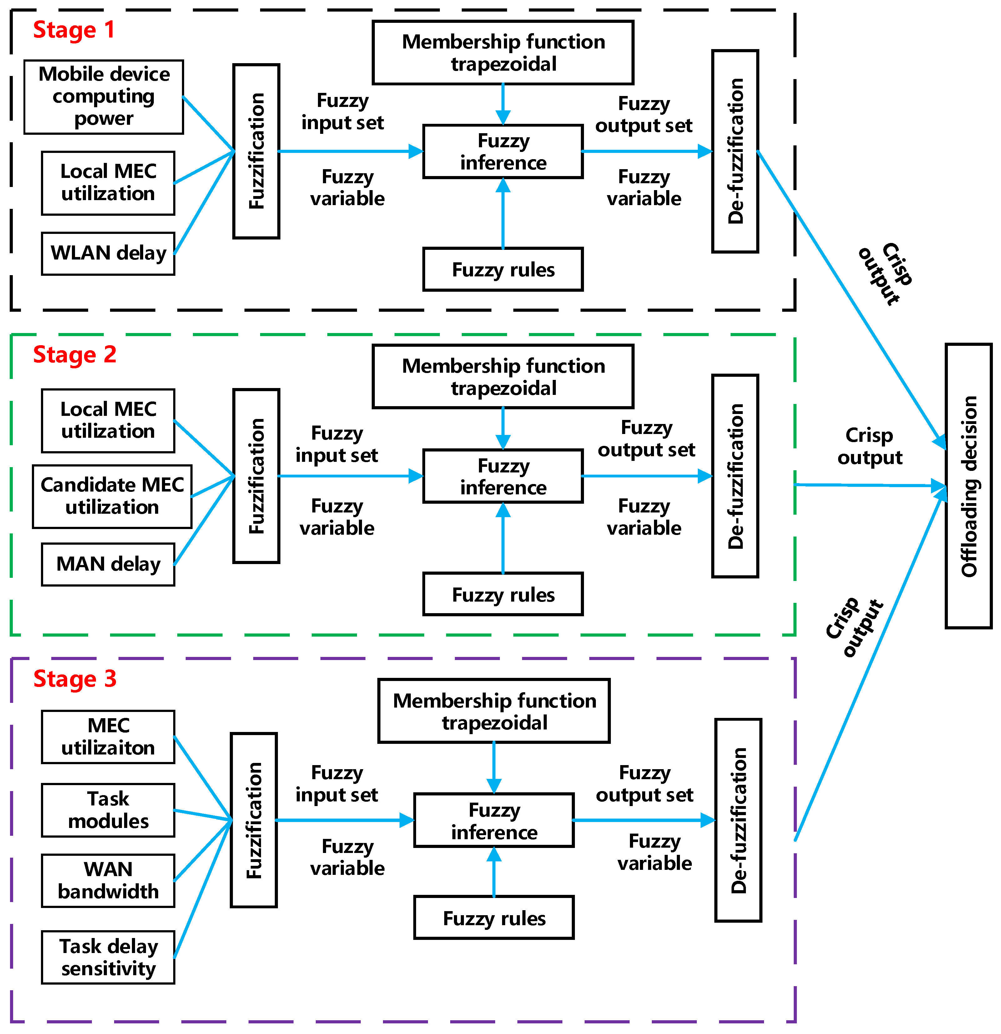
A three-stage fuzzy logic system is proposed in this paper to efficiently offload tasks in multi-layer MEC networks. Since this paper uses 10 input variables, each of which has three language variables to describe its degree, if single-layer FLS is used, the fuzzy rule will reach . However, if the 10 input variables are divided into three stages according to 3 + 3 + 4, the stage with most fuzzy rules is only , so this paper uses a three-level fuzzy logic system. The fuzzy logic-based manager can map different factors acting as input parameters to FLS to the value of decision variables. Figure 3 is the fuzzy logic architecture used in this paper. Figure 4 involves task partitioning in addition to offloading decision, which will be elaborated on in the next chapter.
The fuzzy logic system in this paper mainly consists of singleton fuzzifier, fuzzy inference engine, rules, and the centroid de-fuzzifier. These components are shown in Figure 3. Essentially, the three FLS used in the three phases follow the same steps but different values.
In Figure 3, there are three steps in the process of fuzzy logic system.
- The first step is fuzzification. For each input parameter, the clear input set will be converted into the fuzzy input set according to the membership function corresponding to this variable. There are many forms of membership function, such as triangular, gaussian, and trapezoidal form. In this paper, the trapezoidal form is selected (since two out of four points coincide, the medium broken line becomes triangular). Secondly, determining the membership function of each input variable and output variable is critical because it has a great impact on FLS performance. In this paper, the membership function of each fuzzy variable is determined according to paper [25]. As shown in Figure 5, for WLAN delay (represented by ), if a clear input value is 11.5, a vertical line is drawn at the abscissa 11.5, and the ordinate values of the three intersecting points of membership function are 0, 0.1, and 0.5, respectively, then the fuzzy variable after transformation of the clear input value 11.5 is .
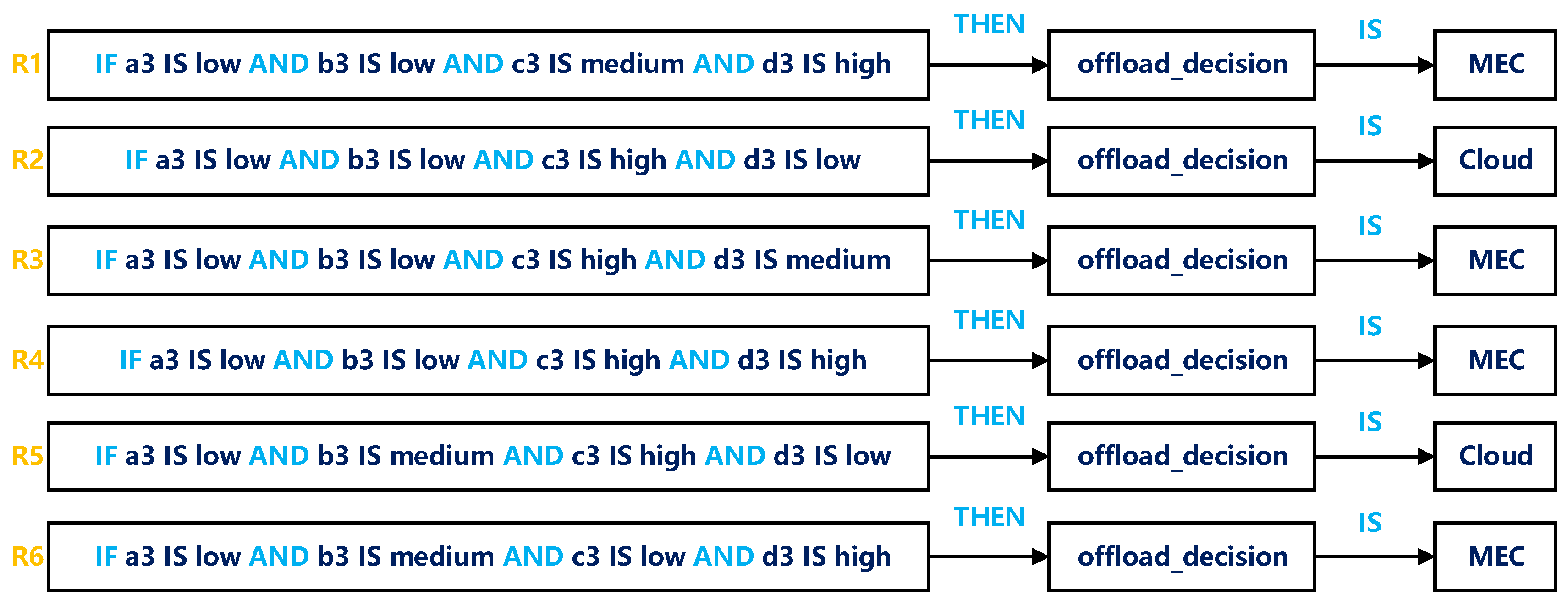
- The second step is inference. As the input of fuzzy inference machine, fuzzy variables match the rules of fuzzy inference machine; some rules are shown in Figure 6. Fuzzy rules are simple if–then statements with conditions and conclusions. It is extremely important to determine fuzzy rules because rules directly determine the overall performance of FLS, and these rules are determined based on experience. The logic AND in the rules are fuzzy operator. It can be described by a minimum value function (as shown in Table 1) or constructed by triangular norm. Since triangular norm is complicated, this paper selects minimum function to construct AND operator. Each value of the output fuzzy variable of the fuzzy reasoning machine, also called rule firing strength, represents the influence of each rule on the output.
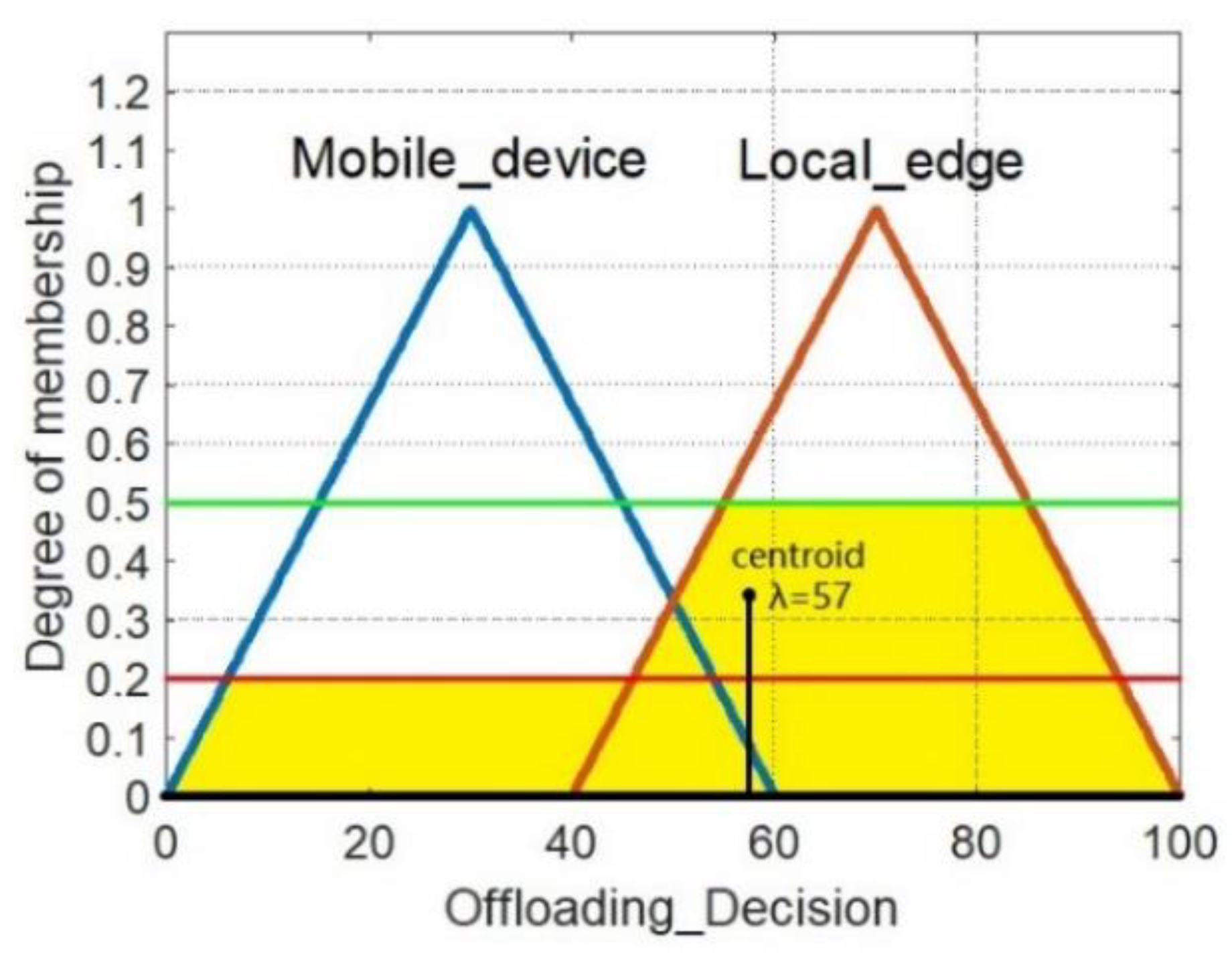
- The third step is de-fuzzification. De-fuzzification denotes to de-fuzzify output fuzzy variables obtained in step 2 according to offloading decision membership function. There are many ways to de-fuzzify a fuzzy number, among which centroid method is the most commonly used. The specific process is shown in Figure 7. If the fuzzy variable obtained is [0.2, 0.5], the corresponding region of mobile device is filled from the bottom up to the position of 0.2. Similarly, fill the area corresponding region to the local MEC server to the position of 0.5, then calculate the centroid of the yellow area in Figure 7, the abscissa λ is 57, if λ is greater than 50, then the final offloading decision is the local MEC server.
3.2. The First Stage of the Proposed FLS
In the first stage, this paper will further illustrate FLS using formulas.
The fuzzy reasoning system used in the first stage has three input variables, namely, WLAN delay, mobile device utilization, and local MEC VM utilization. The number of fuzzy rules used is 33 = 27. There are three linguistic terms for each variable, which are low, medium, and high respectively.
Due to the large number of rules, this paper gives only a few of the rules shown in Figure 6 as examples.
- WLAN delay (a1): The level of WLAN delay affects whether tasks of mobile devices can offload. If the delay is too high, it is a wise choice to process tasks on mobile device.
- Mobile device utilization (): This paper models a mobile device as analyzer and manager. Mobile device utilization needs to consider both the remaining power and maximum computing resources , which are monitored by the manager. This paper applies a weighted sum of and , as shown in Equation (1), where the weights and are given by experience. If the value of is small, WLAN delay needs checking afterwards. If the WLAN delay is high, then this task will operate on the mobile device. If the latency and VM utilization of the MEC server is low, offloading tasks to the MEC server is more appropriate.
- VM utilization of the local MEC server (c1): Generally, it is better to offload tasks to the local MEC server in order not to consume mobile device resources. However, the MEC server’s VM utilization is capped, and offloading to MEC servers all the time can result in an excessive task failure rate. Therefore, the above three aspects need to be considered comprehensively to achieve a relative balance.
In the first stage of FLS, this paper uses three language variables, low, medium, and high, as the grades of the three input variables. The membership functions corresponding to the three input variables and offloading decision are shown in Figure 8.
The following takes the first stage as an example and uses the formula to elaborate in detail.
- The first step of FLS is fuzzification. Fuzzification is the process of converting the values of clear input variables (e.g., Equation (2)) to fuzzy values by using member functions that associate levels with each language term, and each variable after fuzzification corresponds to Formula (3a–c):
- In the second step of reasoning, it is assumed that only two rules, R1 and R2, are defined in the rule set. If the WLAN delay, mobile device utilization, and local MEC VM utilization are 1 ms, 40%, and 80%, respectively, then Equation (4) can be used to calculate the fuzzy value for selecting local MEC server or not.where:After substituting the specific values, we can obtain:
- In the third step of de-fuzzification, the centroid calculation formula in the centroid de-fuzzifier is:
After applying the centroid de-fuzzifier, the output of FLS becomes a clear value between 0 and 100. Tasks will run on mobile devices if ω is less than 50, and be offloaded to local MEC if ω is between 50 and 100.
3.3. The Second Stage of the Proposed FLS
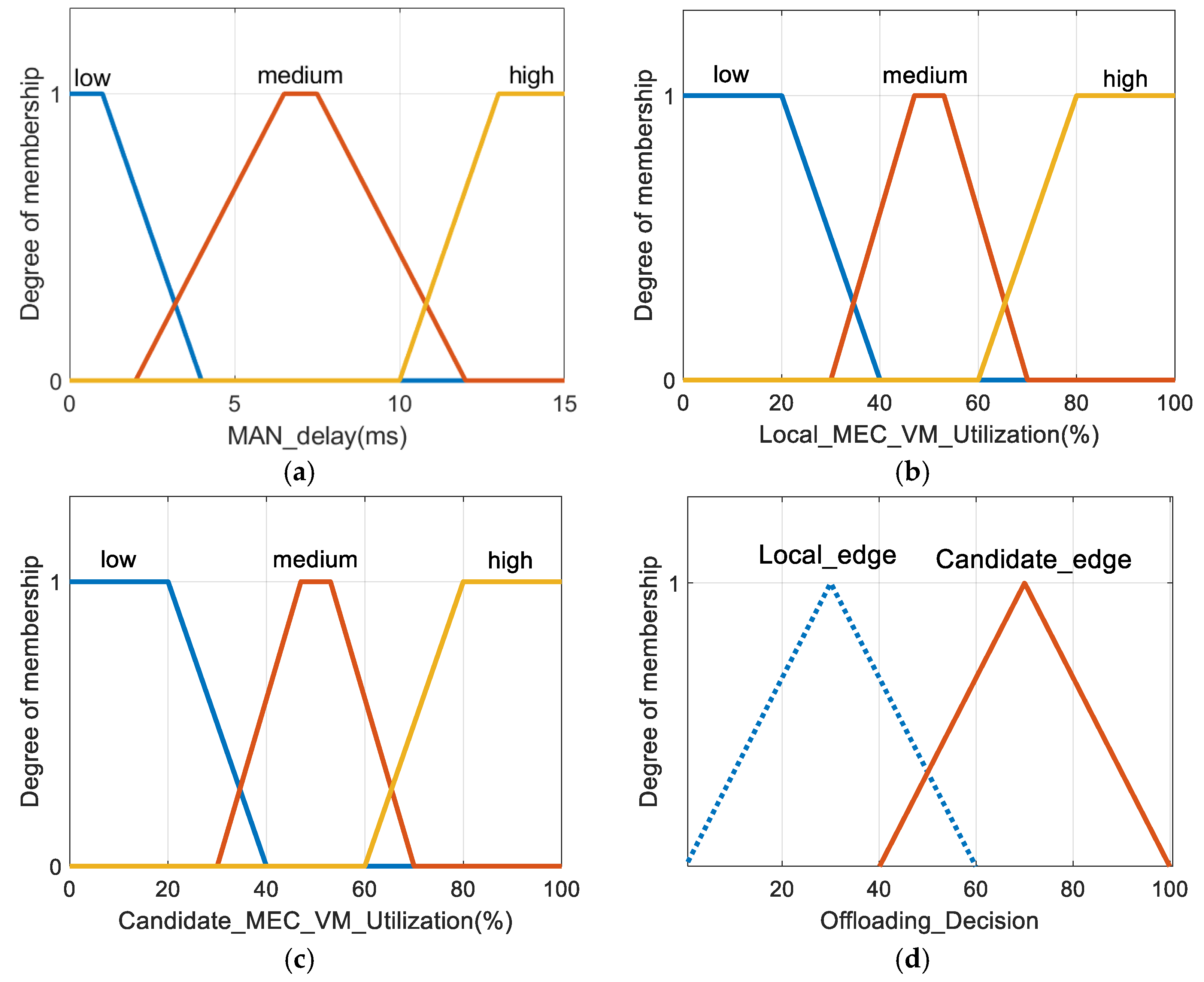
The second stage of FLS was established considering that when the local MEC server is overloaded, its task could be handled by an alternative MEC server connected to the same MAN. The fuzzy reasoning system used in the second stage is similar to the first stage, but there are differences in input variables, fuzzy member functions, and fuzzy rules. The second stage has three input variables, each variable has three levels, and the number of fuzzy rules is also 27. The three input variables are MAN delay, VM utilization of the local MEC server, and VM utilization of the best alternative MEC servers.
- MAN delay (): When the number of users using MAN is very high, MAN delay becomes an important bottleneck in the proposed architecture when selecting the best MEC serve. If the MAN delay is greater than the threshold, offloading tasks to the local MEC server is a more sensible choice.
- Average VM utilization of the local MEC server (): In order not to consume MAN’s network resources, it is a good choice to offload tasks to the alternative MEC server. However, some hotspots have very high user densities, and offloading to the local MEC server all the time may result in a high task failure rate. Therefore, in this case, if the MAN delay is not too high, it is wise to offload to the alternative MEC server.
- Average VM utilization of the best alternative MEC server (): This paper assumes that the MAN utilization cost of offloading to any alternative MEC server is the same, so selecting the alternative MEC server with the lowest VM utilization is the best. If VM utilization is lower in the alternative MEC server compared to the local MEC server, coupled with lower MAN delay, it is better to offload to the alternative MEC.
In the second stage, the language variables of low, medium, and high are still used as the levels of the three input variables. The membership functions corresponding to the three input variables and offloading decision are shown in Figure 9.
3.4. The Third Stage of the Proposed FLS
The third phase takes into account the attributes of the task (number of task modules and delay sensitivity), both of which are determined by the application’s configuration file. So, there are four input variables, each of which has three language levels, and the number of fuzzy rules increases to 34 = 81. The four input variables are:
- WAN bandwidth (a3): WAN bandwidth is a significant indicator. If the WAN delay is higher than the QoS requirements of the application, or the network congestion is too high to cause data transmission failure, the cloud server should not be offloaded.
- Number of task modules (b3): Normally, the number of task modules determines the execution time of a task. If a task is complicated and has many modules, it should be offloaded to the cloud server to reduce service time.
- Task delay sensitivity (c3): Delay sensitivity represents the tolerance of a task to high delay. If the value is high, the service time should be as small as possible. In the next chapter, we will elaborate how FLS reduces delay from the perspective of task partitioning.
- Average MEC server utilization picked by the second stage (d3): Congestion is defined as the average VM usage of MEC VMs exceeds the threshold value. In this paper, four VMs are running on each MEC server, so VM utilization represents the average utilization of all VM running on that MEC server.
In the third stage, the language variables of low, medium, and high are still used as the levels of the three input variables. The membership functions corresponding to the four input variables and offloading decision are shown in Figure 10.
4. Task Partitioning
The FLS decision is a binary compromise result that balances many factors when making offloading decisions, and thus cannot meet the requirements for high delay sensitive applications such as AR. This chapter considers whether this binary decision can be quantitatively offloaded in proportion, namely, task partitioning, which enables parallel processing of task modules. The purpose is to make full use of the remaining computing capabilities of mobile devices and MEC servers, reduce the weighted delay of tasks to the maximum extent, and improve users’ QoS.
4.1. Partitioning Model
This paper models a mobile device as an analyzer and a manager. The analyzer is responsible for determining which modules of an application can be offloaded based on application type and device hardware conditions. Manager monitors the remaining battery and memory usage of the mobile device. However, if the tasks of an application are composed of nonlinear modules with complex internal dependencies, its tasks cannot be partitioned [10]. These applications are not considered, and all the applications used in this paper can be partitioned into several linearly independent sub-modules. In [11], an application program based on augmented reality ARkit framework is proposed. The submodules of the program task are linearly independent and can be executed on mobile device, MEC server and cloud server. In this way, each module of the task realizes parallel processing. The advantage of parallel processing is that it greatly improves efficiency, but the disadvantage is that it will occupy extra network resources. The general process of task partitioning in this chapter is as follows; it should be noted that the two stages of task partitioning have symmetry:
- In the first stage of FLS proposed in chapter 3, if the decision made by FLS is to execute on mobile device, the tasks do not need partitioning. However, if the decision is made to offload tasks to the local MEC server (called condition 1), the mobile device computing power at this point is not sufficient to operate the full tasks, but it can still operate some modules of the tasks. Therefore, MEM will partition tasks according to the optimal task partitioning rate of stage 1. Assuming that the number of modules of a task is , and the optimal task partitioning ratio of the stage 1 is , thus modules of tasks will be executed on mobile device, and the rest modules of tasks will be executed on the local MEC server. When entire tasks are complete, the final output data will be transmitted back to the mobile device.
- In the third stage of FLS, if the decision made by FLS is to execute on the best MEC server, there is no need to partitioning tasks at this time. However, if the decision is to offloading to cloud server (called condition 2), the VM of the best MEC server at this time is not enough to process the whole tasks, but it can still process parts of modules of the tasks. Therefore, MEM will divide the task according to the optimal task partitioning rate of stage 2. Assuming that the number of modules of the task is , and the optimal task partitioning ratio of stage 2 is , thus modules of tasks will be executed on the best MEC server picked by the second stage of FLS, and the rest modules of tasks will be executed on cloud server. When the entire tasks are complete, the final output data will be transmitted back to the local MEC server.
The program block diagram of the whole process above is shown in Figure 11.
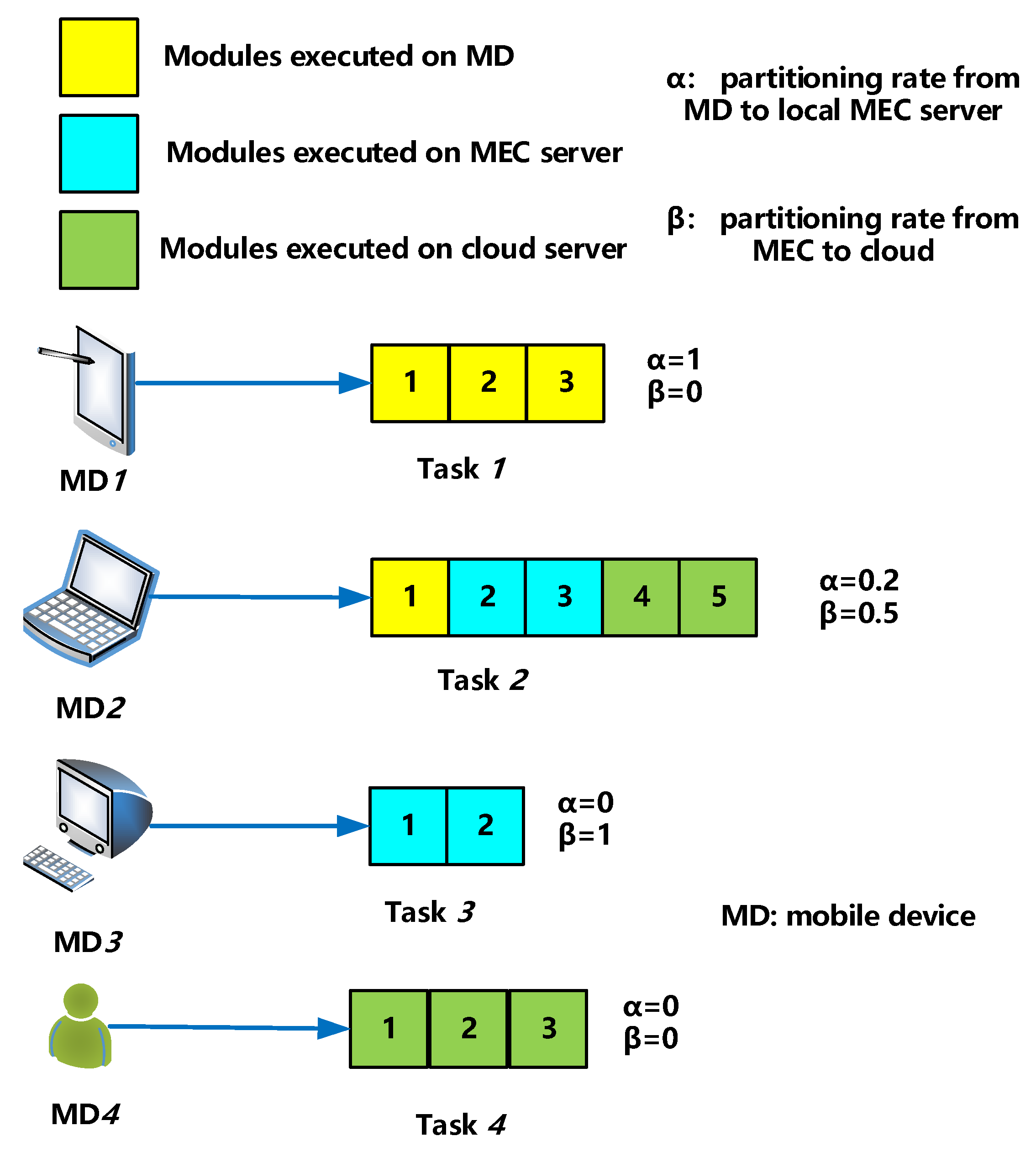
Figure 12 is a simple diagram of task partitioning. For user 1’s task 1, each module of task 1 is executed on a mobile device, and neither the MEC nor the cloud server operates any module of the task, so for task 1, . For user 2’s task 2, one-fifth of the modules are executed on mobile device, and the rest are offloaded to the local MEC server, which then offloads half of the modules to the cloud server, so for task 2, , .
Because it is too sophisticated to incorporate the two task partitioning questions into one constrained optimization problem, this paper divides task partitioning into two stages: stage 1 (when condition 1 is satisfied) and stage 2 (when condition 2 is satisfied). The remainder of this chapter is how to model and solve the optimal task partitioning ratios and . Since the results of the stage 2 are used in stage 1, this paper starts from stage 2.
4.2. Partitioning of Stage 2
According to chapter 3, MEM masters the task attributes of each mobile device application. And this paper ignores the time required to split, aggregate, and store tasks. In addition, the size of the calculated results is small enough that the download delay is negligible.
The task delay of the stage 2 includes the following parts.
- Calculation delay of the best MEC server: is the optimal task partitioning rate of stage 2, which represents the proportion of task modules to be executed on the best MEC server . These task modules come from (mobile device), thereforewhere:
- is the computing resource assigned by the best to task modules from (modules/s).
- is the number of CPU cycles required by the best MEC server to calculate one module of tasks [18].
- is the number of task modules offloaded from to .
- Transmission delay of the best MEC server: In Figure 5, all mobile devices communicate with MEC servers via WLAN, which covers the area from MEC server to cloud server. As the transmission time of high-speed WAN is very short and the data loss rate is not considered, the transmission delay of long-distance WAN is determined by the propagation time defined as tWAN [19].
- Computing delay of cloud server: MEM allocates available computing resources of cloud server to each task for parallel computing when it receives part of modules from the best MEC server.where:
- is the computing resources allocated by the cloud server to the best MEC server (modules/s).
- Return delay of cloud server: This paper assumes that the transmission delay tWAN from the best MEC server to the cloud server is the same as that from the cloud server back to the best MEC server.
The total delay of the second stage is
The maximum value function is selected here because if the calculation delay of the best MEC server is low, it needs to wait for the return result from the cloud server. If the calculation delay of the best MEC server is high, the calculation delay of the best MEC server is the total delay.
The constraint optimization problem at this stage can be modeled as:
The first constraint in the optimization problem P1 indicates that the computing resources required for the execution of the task module from should not exceed the maximum computing resources of the best MEC server . The unit of is modules/s. The optimization variable is the optimal task partitioning ratio .
Theorem 1.
The optimal task partitioning ratio in stage 2 can be calculated as.
Proof of Theorem 1.
Because is positively correlated with , plus , therefore . In addition, is negatively correlated with ; therefore, . For , let the abscissa of the intersection of and be and the ordinate be . It can be seen that with the increase of , the maximum function first decreases from to , and then increases from to . The abscissa corresponding to the intersection of the above two functions is the minimum point.
For constraint condition 1, it can be transformed into . When , is the optimal solution, otherwise the optimal solution is .
4.3. Partitioning of Stage 1
The task delay of stage 1 includes the following parts.
- Calculation delay of mobile device: is the optimal task partitioning rate of stage 1, which represents the proportion of task modules to be executed on .where:
- The computing resource of is (modules/s).
- Ci is the CPU cycles required for calculating a module of the task of MDi.
- ni is the number of task modules executed on MDi.
- Transmission delay of mobile device: Since the distance between mobile device and MEC server is short, the propagation delay is ignored, and the transmission delay is defined aswhere:
- vtrans is the task transmission rate in modules/s, which is considered a constant in this paper.
- Calculation delay of the local MEC server: When local MEC server receives a task from a mobile device, the task modules will be further divided according to the optimal partitioning ratio of stage 1, and the number of task modules offloaded to the local MEC server will be denoted as . This part of delay is already considered in stage 2, so there is no need to calculate twice.
- Return delay of the local MEC server: the value of this delay is the same as mobile device’s transmission delay, both of which areThen, the total delay of the first stage iswhere:
- is the total delay of stage 2.
The constraint optimization problem at this stage can be modeled as
The first constraint in P2 indicates that the task modules executed on mobile device should not exceed the maximum computing resource of this mobile device. The unit of is modules/s, which is obtained by the mobile device manager. The optimization variable is the optimal task partitioning ratio of stage 1.
Theorem 2.
The optimal task partitioning ratioshould be discussed in two cases:
- If , that is, the calculation delay of the best MEC server in the second stage is greater than the sum of the transmission delay and the calculation delay of cloud server, then
- If, then
The proof process of these two cases is similar to that of the stage 2, so it is omitted. The overall framework of the proposed scheme is shown in Algorithm 1.
| Algorithm 1. Offloading decision for task modules’ placement. |
| 1. Input: task modules n |
| 2. Output: target of offloading decision O |
| 3. Apply the first-stage fuzzy logic system |
| 4. Calculate the crisp output value λ1 |
| 5. If λ1 <= 50 then |
| 6. O = mobile device |
| 7. else |
| 8. Calculate the task partitioning ratio of stage 1: α |
| 9. O = αn modules on mobile device + (1 − α) ×n modules on local MEC server |
| 10. end if |
| 11. Apply the second-stage fuzzy logic system |
| 12. Calculate the crisp output value λ2 |
| 13. If λ2 <= 50 then |
| 14. O = local MEC server |
| 15. else |
| 16. O = candidate MEC server |
| 17. end if |
| 18. Apply the third-stage fuzzy logic system |
| 19. Calculate the crisp output value λ3 |
| 20. If λ3 <= 50 then |
| 21. O = Best MEC of the second stage |
| 22. else |
| 23. Calculate the task partitioning ratio of stage 2: β |
| 24. O = (1−α) × β×n modules on the best MEC server + (1−α) ×(1−β) ×n modules on cloud server |
| 25. end if |
5. Simulation and Analysis
5.1. Parameter Settings
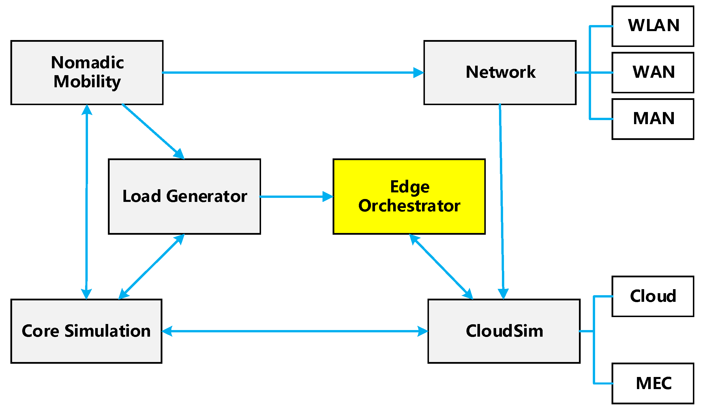
EdgeCloudSim is an open-source project released by Cagatay Sonmez et al. in 2018 and is being continuously updated [25]. Based on CloudSim, the project provides five modules: core simulation, network, load generator, mobile module, and edge orchestrator, as shown in Figure 13. In addition, application configuration files can be customized based on the characteristics of different applications to simulate the performance of the proposed schemes. Ref. [26] presents an augmented reality application program, which aims to promote operators to work in an industrial man-machine collaborative environment with mobile robots. In [27], an on-board infotainment application is proposed, which integrates the information part with the entertainment part and provides a unified platform for drivers and passengers. In [28], a novel unmanned aerial vehicle-based intelligent medical system for large-scale disinfection, thermal image acquisition, and patient identification is proposed, which can be applied to suppress the transmission of coronavirus disease. In our simulation, workers in the factory offload the tasks received by mobile robots to remote servers (including local, candidate, or cloud servers), and the remote servers guide the robots to carry out factory operations. The intelligent medical system based on UAV unloads the collected thermal images and patient information to the remote server, which provides heat detection services. Similarly, infotainment and compute-intensive applications send tasks to remote servers that provide related services. It is worth noting that the above four applications, AR, infotainment, health, and compute-intensive applications, are abstracted in the four application configuration files respectively. The details of applications in the literature are not further discussed in this paper.
The configuration parameters of the above four applications are summarized in Table 2. Usage percentage is the percentage of mobile devices running the specific APP in the total mobile devices. Task interval reflects the frequency of tasks generated by the APP. Delay sensitivity has been introduced before and is the tolerance of tasks with high delay. The mobile device generates tasks during the active period and waits during the idle period. Upload/download modules is the number of modules sent or received by the server each time. Task modules is the number of modules per application task. VM utilization on the mobile device/MEC/cloud server is the VM space occupied by APP tasks executing on the mobile device/MEC/cloud server, respectively.
Table 3 shows the configuration file parameters of EdgeCloudSim simulation in this paper. The warm-up period is the time during which the system develops to a stable state before simulation. Simulation time includes a warm-up period. Multiple iterations are needed to ensure the reliability of the results. The CPU speed of each MEC and cloud server’s VM is 10 modules/s and 100 modules/s, respectively. The MEC and cloud server run 8 VMs and 4 VMs, respectively. Type1, 2 and 3 respectively represent areas with different attractiveness levels. The higher the attractiveness, the higher the mean dwell time and the higher the user density.
The rival schemes are as follows: band-based scheme (marked as net), utilization-based scheme (marked as utilization), hybrid scheme (marked as hybrid) [4] and Flores scheme (marked as comp). Flores scheme was adjusted by Cagatay Sonmez et al. [5], which is finally used in this paper. This method establishes a one-stage FLS with four parameters: WAN bandwidth, CPU speed, delay sensitivity, and data size, where delay sensitivity defines the urgency of the tasks, and the AR application has the highest delay sensitivity value. In addition, the data size is normalized. The data size and the maximum data size are defined as and , respectively, so the normalized data size calculation formula is . These four parameters also have three levels of low, medium, and high. The FLS of this scheme contains 69 rules, and each rule is an if–then statement containing the above four parameters. If the final output value is greater than 50, the task will be offloaded to the cloud server; otherwise, the task will be offloaded to the local MEC server. The scheme in this paper is marked as ours.
When the WAN bandwidth is higher than the bandwidth threshold , bandwidth-based solution offloads all tasks to the cloud server. Therefore, bandwidth-based scheme tends to offload tasks to the cloud server when network resources are sufficient. If the CPU utilization of MEC server’s VMs is less than the utilization threshold , the utilization-based solution will offload all tasks to the MEC server. Therefore, the utilization-based solution tends to offload tasks to the MEC server when computing resources are sufficient.
The hybrid scheme is the combination of band-based scheme and utilization-based scheme. If the WAN bandwidth is higher than and the CPU usage of MEC server’s VMs is greater than , the hybrid scheme offloads all tasks to the cloud server. If the WAN bandwidth is lower than or the CPU usage of MEC server’s VMs is less than , the hybrid scheme offloads tasks to the MEC server. This paper adopts the threshold value in [5], that is, , .
5.2. Results and Analysis
This section evaluates five performance indicators of the five schemes described in Section 5.1, namely, task failure rate, service time, network latency, processing time, and average VM utilization.
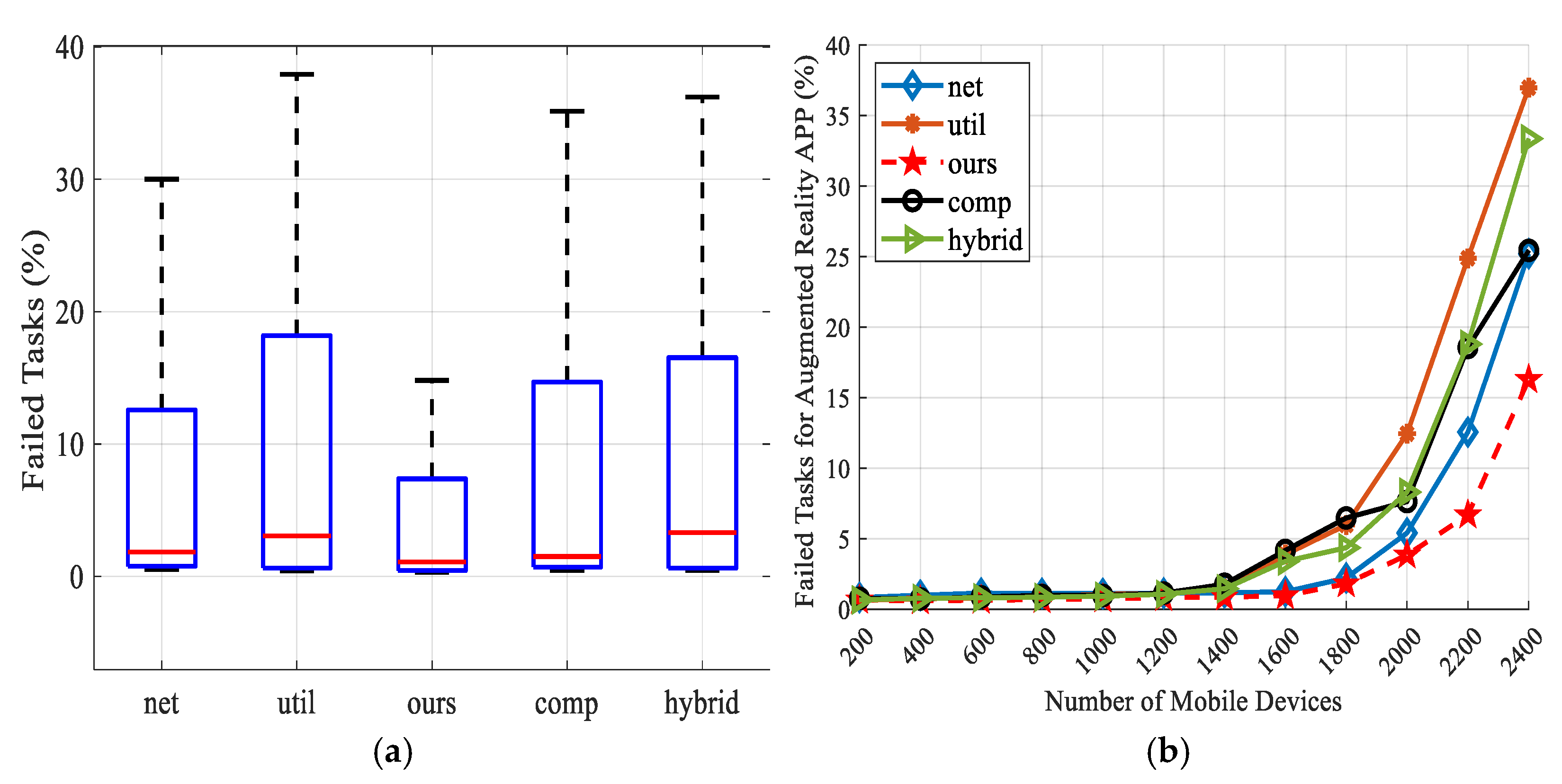
Figure 14 shows the average task failure rate for overall and three applications. Failed tasks include tasks discarded due to network congestion and insufficient computing resources on the VM. When the computing resources of the VM on the MEC server are crowded, the utilization-based and hybrid schemes transfer the load to the cloud server. Therefore, some tasks will fail due to WAN bandwidth limitations. In addition, the other two schemes have relatively poor performance when the number of devices exceeds 1800 because they ignore the influence of WLAN delay. The scheme in this paper takes WLAN delay into account in the first stage of FLS, and the task modules can be partitioned independently, so the average task failure rate is reduced. As shown in Figure 14b–d, the conclusions are the same for AR, health monitoring, and compute-intensive apps.
AR and health monitoring APPs have higher delay sensitivity and therefore require faster response, namely, shorter average service time. Infotainment and compute-intensive APP tasks have more modules and require more VM space. It can be seen from Figure 15a that the average service time performance of our scheme is the best. Utilization-based and hybrid schemes tend to transfer tasks to local MEC server, so the processing time increases when the number of devices increases, resulting in long service time. For applications with higher delay sensitivity, as shown in Figure 15b, it can be seen that when the number of devices is less than 1400, the bandwidth-based scheme has the worst performance, because this scheme tends to offload all modules of the task to the cloud server. For APP with a large number of task modules, the bandwidth-based scheme is more inclined to offload to the cloud under the bandwidth limit. As can be seen from Figure 15c,d, bandwidth-based scheme provides better average service time performance than the other three schemes except ours. In our scheme, tasks will be split when the number of task modules is large, making full use of the remaining computing capacity of each layer, and using three-stage FLS to make a better offloading decision. Therefore, the performance is better than the other four schemes. It is worth noting that ours is comparable to bandwidth-based scheme when the number of devices exceeds 2000. However, the bandwidth-based scheme has a higher task failure rate, so many task modules are discarded, resulting in reduced service time.
Average network latency and average processing time are components of average service time. It can be seen from Figure 16a and Figure 17a that bandwidth-based schemes tend to offload to the cloud server, so they basically have the highest network latency and the lowest processing time. Our scheme utilizes the three layers of mobile device, MEC, and cloud server, so the network delay and processing time are relatively balanced, thus the service time is good. In addition, for APP such as infotainment with a large number of modules, our scheme offloads some task modules to the cloud server due to task partitioning, so the processing time is shortest. For AR APP with high latency sensitivity, ours utilizes indicators of WLAN delay, MAN delay and WAN bandwidth of the three-stage FLS to provide better network delay performance with low task failure rate.
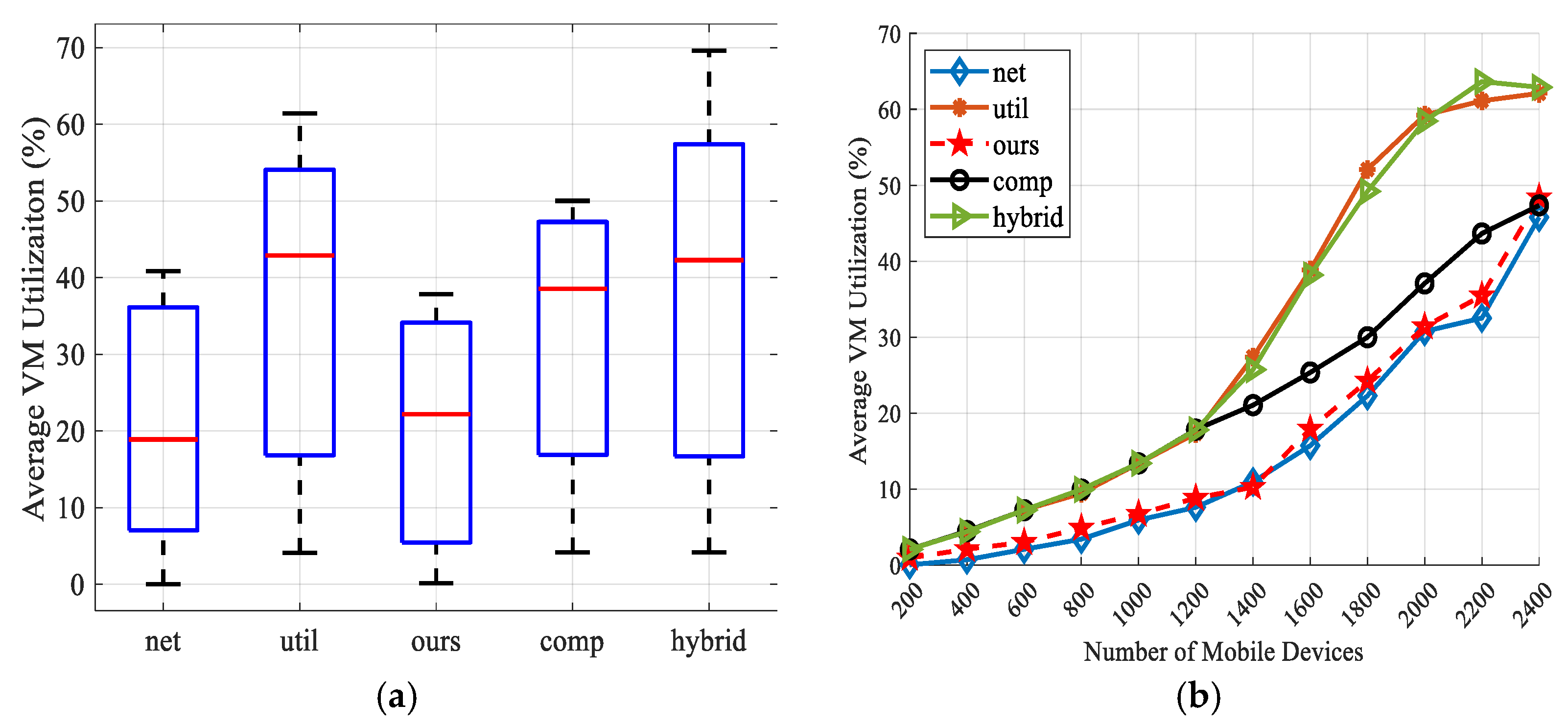
As for the average VM utilization rate, our scheme makes use of the computing resources of mobile device. As can be seen from Table 3, the average VM utilization rate of the four apps executed on a mobile device is very high, while executing on cloud server is very low. Bandwidth-based scheme tend to be offloaded to the cloud server. Therefore, according to Figure 18, it has the best performance in this indicator. Utilization-based and hybrid schemes tend to offload to the local MEC server when the VM utilization is satisfied. Therefore, when the number of devices exceeds 1200, the VM utilization of the local MEC server is too high and the performance is the worst. Since the FLS of the Flores scheme only considers four parameters and has no task partitioning ratio, which is relatively simple, so our scheme has advantages over the remaining three schemes.
6. Conclusions and Future Work
In a dynamic environment that supports MEC networks, tasks of mobile devices are unknown and the state of computing resources changes rapidly based on offloading requests; therefore, task offloading management is a difficult online problem. In addition, without proper task offloading orchestration, mobile devices, MEC, and cloud servers are underutilized, leading to increased task failure rates and longer service times. For large tasks and time-sensitive tasks, task scheduling is more important. In order to solve the above problems, this paper proposes a fuzzy-based MEM architecture with task partitioning, in which MEM controls the network resources and computing resources as well as the task requirements of each mobile device. The proposed architecture is a three-stage FLS system with two optimal task partitioning ratios. It takes into account the bandwidth of WLAN, MAN, and WAN, the CPU utilization of mobile device, MEC, and cloud server, and task attributes, and dynamically determines the offloading target of the task through various rules. Moreover, due to the independence of the task module in this paper, the task will be divided during offloading, and each module will execute independently on each layer, and finally return to the mobile device, so as to reduce the complexity and service time of the task. Applications with high time sensitivity and large task scale have better performances. Finally, to evaluate the proposed architecture, infotainment, AR, health monitoring, and compute-intensive applications were used, and the proposed scheme were compared with four competing scheme. According to the evaluation, the scheme in this paper is superior to the competing schemes in terms of task failure rate and service time, and also has good performance in terms of average VM utilization.
In future work, we will consider using artificial fish swarm algorithm to realize efficient task offloading in the MEC network under the environment of Internet of vehicles. In addition, divisible and indivisible tasks will be considered under the same architecture as well as energy resource allocation.
Author Contributions
Conceptualization, Y.S.; methodology, J.C.; software, J.C.; investigation, Y.S.; data curation, C.J.; writing—original draft preparation, J.C.; writing—review and editing, J.C.; visualization, C.J.; supervision, J.L.; project administration, S.N. All authors have read and agreed to the published version of the manuscript.
Funding
This research received no external funding.
Institutional Review Board Statement
Not applicable.
Informed Consent Statement
Not applicable.
Data Availability Statement
The data that support the findings of this study are available from the corresponding author upon reasonable request.
Conflicts of Interest
The authors declare no conflict of interest.
References
- Pham, Q.-V.; Fang, F.; Ha, V.N.; Piran, M.J.; Le, M.; Le, L.B.; Hwang, W.-J.; Ding, Z. A Survey of Multi-Access Edge Computing in 5G and Beyond: Fundamentals, Technology Integration, and State-of-the-Art. IEEE Access 2020, 8, 116974–117017. [Google Scholar] [CrossRef]
- Mach, P.; Becvar, Z. Mobile Edge Computing: A Survey on Architecture and Computation Offloading. IEEE Commun. Surv. Tutor. 2017, 19, 1628–1656. [Google Scholar] [CrossRef]
- Tran Trong, K.; VanDung, N.; Huh, E.-N. Fuzzy-Based Mobile Edge Orchestrators in Heterogeneous IoT Environments: An Online Workload Balancing Approach. Wirel. Commun. Mob. Comput. 2021, 2021, 5539186. [Google Scholar]
- Nguyen, V.; Khanh, T.T.; Nguyen, T.D.T.; Hong, C.S.; Huh, E.-N. Flexible computation offloading in a fuzzy-based mobile edge orchestrator for IoT applications. J. Cloud Comput.-Adv. Syst. Appl. 2020, 9, 66. [Google Scholar] [CrossRef]
- Sonmez, C.; Ozgovde, A.; Ersoy, C. Fuzzy Workload Orchestration for Edge Computing. IEEE Trans. Netw. Serv. Manag. 2019, 16, 769–782. [Google Scholar] [CrossRef]
- Khanh, T.T.; Hai, T.H.; Hossain, M.D.; Huh, E.N. Fuzzy-Assisted Mobile Edge Orchestrator and SARSA Learning for Flexible Offloading in Heterogeneous IoT Environment. Sensors 2022, 22, 4727. [Google Scholar] [CrossRef]
- Hossain, M.D.; Sultana, T.; Hossain, M.A.; Hossain, M.I.; Huynh, L.N.T.; Park, J.; Huh, E.-N. Fuzzy Decision-Based Efficient Task Offloading Management Scheme in Multi-Tier MEC-Enabled Networks. Sensors 2021, 21, 1484. [Google Scholar] [CrossRef] [PubMed]
- Bi, S.; Zhang, Y.J. Computation Rate Maximization for Wireless Powered Mobile-Edge Computing with Binary Computation Offloading. IEEE Trans. Wirel. Commun. 2018, 17, 4177–4190. [Google Scholar] [CrossRef]
- Messous, M.-A.; Senouci, S.-M.; Sedjelmaci, H.; Cherkaoui, S. A Game Theory Based Efficient Computation Offloading in an UAV Network. IEEE Trans. Veh. Technol. 2019, 68, 4964–4974. [Google Scholar] [CrossRef]
- Kuang, Z.; Li, L.; Gao, J.; Zhao, L.; Liu, A. Partial Offloading Scheduling and Power Allocation for Mobile Edge Computing Systems. IEEE Internet Things J. 2019, 6, 6774–6785. [Google Scholar] [CrossRef]
- Ning, Z.; Dong, P.; Kong, X.; Xia, F. A cooperative partial computation offloading scheme for mobile edge computing enabled internet of things. IEEE Internet Things J. 2019, 6, 4804–4814. [Google Scholar] [CrossRef]
- Jinke, R.; Guanding, Y.; Yunlong, C.; Yinghui, H.; Fengzhong, Q. Partial offloading for latency minimization in mobile-edge computing. In Proceedings of the GLOBECOM 2017—2017 IEEE Global Communications Conference, Singapore, 4–8 December 2017; pp. 1–6. [Google Scholar]
- Deng, R.; Lu, R.; Lai, C.; Luan, T.H.; Liang, H. Optimal Workload Allocation in Fog-Cloud Computing Toward Balanced Delay and Power Consumption. IEEE Internet Things J. 2016, 3, 1171–1181. [Google Scholar] [CrossRef]
- Hossain, M.D.; Sultana, T.; Nguyen, V.; Rahman, W.U.; Nguyen, T.D.T.; Huynh, L.N.T.; Huh, E.-N. Fuzzy Based Collaborative Task Offloading Scheme in the Densely Deployed Small-Cell Networks with Multi-Access Edge Computing. Appl. Sci. 2020, 10, 3115. [Google Scholar] [CrossRef]
- Fan, W.; Liu, Y.A.; Tang, B.; Wu, F.; Wang, Z. Computation Offloading Based on Cooperations of Mobile Edge Computing-Enabled Base Stations. IEEE Access 2018, 6, 22622–22633. [Google Scholar] [CrossRef]
- Karagiannis, V.; Papageorgiou, A. Network-integrated edge computing orchestrator for application placement. In Proceedings of the 2017 13th International Conference on Network and Service Management (CNSM) 2017, Tokyo, Japan, 26–30 November 2017; p. 5. [Google Scholar]
- De Maio, V.; Brandic, I. First Hop Mobile Offloading of DAG Computations. In Proceedings of the 18th IEEE/ACM International Symposium on Cluster, Cloud and Grid Computing (CCGrid), Washington, DC, USA, 1–4 May 2018; pp. 83–92. [Google Scholar]
- Zhao, J.; Zhou, L.; Zhang, R.; He, Y.; Deng, J. In EdgeCloudSim-based Modelling on Power Distribution Internet of Things and Task Offloading Strategy. In Proceedings of the 2021 International Conference on Power System Technology, POWERCON 2021, Haikou, China, 8–9 December 2021; Institute of Electrical and Electronics Engineers Inc.: Haikou, China, 2021; pp. 1843–1847. [Google Scholar]
- Nguyen, V.; Khanh, T.T.; Oo, T.Z.; Tran, N.H.; Huh, E.-N.; Hong, C.S. Latency Minimization in a Fuzzy-Based Mobile Edge Orchestrator for IoT Applications. IEEE Commun. Lett. 2021, 25, 84–88. [Google Scholar] [CrossRef]
- Ren, J.; Yu, G.; Cai, Y.; He, Y. Latency optimization for resource allocation in mobile-edge computation offloading. IEEE Trans. Wirel. Commun. 2018, 17, 5506–5519. [Google Scholar] [CrossRef]
- Ren, J.; Yu, G.; He, Y.; Li, G.Y. Collaborative Cloud and Edge Computing for Latency Minimization. IEEE Trans. Veh. Technol. 2019, 68, 5031–5044. [Google Scholar] [CrossRef]
- Avgeris, M.; Spatharakis, D.; Dechouniotis, D.; Leivadeas, A.; Karyotis, V.; Papavassiliou, S. ENERDGE: Distributed Energy-Aware Resource Allocation at the Edge. Sensors 2022, 22, 660. [Google Scholar] [CrossRef] [PubMed]
- Xue, M.; Wu, H.; Li, R.; Xu, M.; Jiao, P. EosDNN: An Efficient Offloading Scheme for DNN Inference Acceleration in Local-Edge-Cloud Collaborative Environments. IEEE Trans. Green Commun. Netw. 2022, 6, 248–264. [Google Scholar] [CrossRef]
- Wu, H.; Wolter, K.; Jiao, P.; Deng, Y.; Zhao, Y.; Xu, M. EEDTO: An Energy-Efficient Dynamic Task Offloading Algorithm for Blockchain-Enabled IoT-Edge-Cloud Orchestrated Computing. IEEE Internet Things J. 2021, 8, 2163–2176. [Google Scholar] [CrossRef]
- Sonmez, C.; Ozgovde, A.; Ersoy, C. EdgeCloudSim: An environment for performance evaluation of edge computing systems. Trans. Emerg. Telecommun. Technol. 2018, 29, e3493. [Google Scholar] [CrossRef]
- Lotsaris, K.; Fousekis, N.; Koukas, S.; Aivaliotis, S.; Kousi, N.; Michalos, G.; Makris, S. Augmented Reality (AR) based framework for supporting human workers in flexible manufacturing. Procedia CIRP 2021, 96, 301–306. [Google Scholar] [CrossRef]
- Guo, J.; Song, B.; He, Y.; Yu, F.R.; Sookhak, M. A Survey on Compressed Sensing in Vehicular Infotainment Systems. IEEE Commun. Surv. Tutor. 2017, 19, 2662–2680. [Google Scholar] [CrossRef]
- Kumar, A.; Sharma, K.; Singh, H.; Naugriya, S.G.; Gill, S.S.; Buyya, R. A drone-based networked system and methods for combating coronavirus disease (COVID-19) pandemic. Future Gener. Comput. Syst.-Int. J. Esci. 2021, 115, 1–19. [Google Scholar] [CrossRef]
Figure 1.
Multi-user MEC scenario.

Figure 2.
Schematic diagram of three-layer MEC network architecture.

Figure 3.
Fuzzy inference system for placement problem.

Figure 4.
Task partitioning module in FLS.

Figure 5.
Fuzzy diagram of variables.

Figure 6.
Partial rules of the third stage.

Figure 7.
Schematic diagram of center of mass method de-blurring.

Figure 8.
Membership functions of the first stage. (a) Membership function of WLAN delay; (b) mobile device utilization; (c) local MEC server’s average VM utilization; (d) offloading decision of the first stage.
Figure 8.
Membership functions of the first stage. (a) Membership function of WLAN delay; (b) mobile device utilization; (c) local MEC server’s average VM utilization; (d) offloading decision of the first stage.

Figure 9.
Membership functions of the second stage. (a) Membership function of MAN delay; (b) average VM utilization of the local MEC server; (c) average VM utilization of the best candidate MEC server; (d) offloading decision of the second stage.
Figure 9.
Membership functions of the second stage. (a) Membership function of MAN delay; (b) average VM utilization of the local MEC server; (c) average VM utilization of the best candidate MEC server; (d) offloading decision of the second stage.

Figure 10.
Membership functions of the third stage. (a) Membership function of WAN delay; (b) average MEC server utilization picked by the second stage; (c) number of task modules; (d) task delay sensitivity; (e) offloading decision of the third stage.
Figure 10.
Membership functions of the third stage. (a) Membership function of WAN delay; (b) average MEC server utilization picked by the second stage; (c) number of task modules; (d) task delay sensitivity; (e) offloading decision of the third stage.

Figure 11.
Task partitioning process diagram.

Figure 12.
Task Partitioning diagram.

Figure 13.
Relationship diagram of EdegCloudSim modules.

Figure 14.
Average task failure rate. (a) Overall boxplot; (b) AR APP; (c) health monitoring APP; (d) compute-intensive APP.
Figure 14.
Average task failure rate. (a) Overall boxplot; (b) AR APP; (c) health monitoring APP; (d) compute-intensive APP.


Figure 15.
Average service time. (a) Overall boxplot; (b) health monitoring APP; (c) compute-intensive APP; (d) infotainment APP.
Figure 15.
Average service time. (a) Overall boxplot; (b) health monitoring APP; (c) compute-intensive APP; (d) infotainment APP.

Figure 16.
Average network latency. (a) Overall boxplot; (b) Overall line chart; (c) AR APP.

Figure 17.
Average processing time. (a) Overall boxplot; (b) overall line chart; (c) infotainment APP.
Figure 17.
Average processing time. (a) Overall boxplot; (b) overall line chart; (c) infotainment APP.

Figure 18.
Average VM utilization. (a) Overall boxplot; (b) overall line chart.


Table 1.
Minimum function and truth table of AND.
| Binary AND | |||
|---|---|---|---|
| A | B | AND | min (A, B) |
| 0 | 0 | 0 | 0 |
| 1 | 0 | 0 | 0 |
| 0 | 1 | 0 | 0 |
| 1 | 1 | 1 | 1 |
Table 2.
Application profile parameters.
| AR | Health | Compute | Infotainment | |
|---|---|---|---|---|
| Usage percentage (%) | 30 | 20 | 20 | 30 |
| Task interval (sec) | 2 | 3 | 20 | 7 |
| Delay sensitivity (%) | 0.92 | 0.7 | 0.08 | 0.3 |
| Active/idle period (sec) | 40/20 | 45/90 | 60/120 | 30/45 |
| Upload/download modules | 1500/25 | 20/1250 | 2500/20 | 25/1000 |
| VM utilization on mobile device (%) | 15 | 5 | 60 | 25 |
| VM utilization on MEC server (%) | 6 | 2 | 30 | 10 |
| VM utilization on cloud server (%) | 0.6 | 0.2 | 3 | 1 |
Table 3.
EdgeCloudSim configuration file parameters.
| Parameters | Value |
|---|---|
| Simulation time/warm-up period | 33 min/3 min |
| Number of MECs | 25 |
| Min number of mobile devices | 200 |
| Max number of mobile devices | 2000 |
| WAN/WLAN bandwidth | empirical |
| MAN bandwidth | MMPP/M/1 model |
| MAN bandwidth | 1350 × 1024 Kbps |
| LAN propagation delay | 5 ms |
| Number of VMs per mobile device/MEC/cloud server | 12/8/4 |
| Number of cores per mobile device/MEC/cloud VM CPU | 1/2/4 |
| VM CPU speed per mobile device/MEC/cloud | 5/10/100 e3 modules/s |
| Mobility model | Random Way Point |
| Probability of selecting a location type | Equal |
| Number of locations Type1/2/3 | 2/4/8 |
| Mean dwell time in Type1/2/3 | 2/5/8 min |
| vtrans, tWAN | empirical |
| w1, w2 | 0.4, 0.6 |
Publisher’s Note: MDPI stays neutral with regard to jurisdictional claims in published maps and institutional affiliations. |
© 2022 by the authors. Licensee MDPI, Basel, Switzerland. This article is an open access article distributed under the terms and conditions of the Creative Commons Attribution (CC BY) license (https://creativecommons.org/licenses/by/4.0/).
Share and Cite
MDPI and ACS Style
Shi, Y.; Chu, J.; Ji, C.; Li, J.; Ning, S. A Fuzzy-Based Mobile Edge Architecture for Latency-Sensitive and Heavy-Task Applications. Symmetry 2022, 14, 1667. https://0-doi-org.brum.beds.ac.uk/10.3390/sym14081667
AMA Style
Shi Y, Chu J, Ji C, Li J, Ning S. A Fuzzy-Based Mobile Edge Architecture for Latency-Sensitive and Heavy-Task Applications. Symmetry. 2022; 14(8):1667. https://0-doi-org.brum.beds.ac.uk/10.3390/sym14081667
Chicago/Turabian StyleShi, Yanjun, Jinlong Chu, Chao Ji, Jiajian Li, and Shiduo Ning. 2022. "A Fuzzy-Based Mobile Edge Architecture for Latency-Sensitive and Heavy-Task Applications" Symmetry 14, no. 8: 1667. https://0-doi-org.brum.beds.ac.uk/10.3390/sym14081667
Note that from the first issue of 2016, this journal uses article numbers instead of page numbers. See further details here.