
Theoretical Modeling and Experimental Verification of Elliptical Hyperbolic Hybrid Flexure Hinges
1
College of Mechanical and Electrical Engineering, Changchun University of Science and Technology, Changchun 130022, China
2
College of Mechanical and Electrical Engineering, Jilin Institute of Chemical Technology, Jilin 132021, China
3
Key Laboratory of Air-to-Ground Laser Communication for National Defense, Changchun University of Science and Technology, Changchun 130022, China
*
Author to whom correspondence should be addressed.
Symmetry 2024, 16(3), 345; https://0-doi-org.brum.beds.ac.uk/10.3390/sym16030345
Submission received: 2 February 2024
/
Revised: 12 March 2024
/
Accepted: 12 March 2024
/
Published: 13 March 2024
(This article belongs to the Special Issue Advanced Materials, Structures, Symmetrical Design and Mechanism in Mechanical Engineering)
Abstract
:A flexure hinge composed of elliptical and hyperbolic hybrid configurations is developed and analyzed in this paper. The analytical models of compliance, rotation accuracy, and maximum stress of the flexure hinge are established, and the correctness of the models is validated by finite element analysis and experiments. The influence of structural parameters on compliance and rotation accuracy is discussed. The concept of compliance stress ratio is proposed to assess the deformation capacity of flexure hinges when subjected to the same stress, which provides a basis for quantitatively comparing the comprehensive performance of flexure hinges. The performance of the hybrid flexure hinge is compared with that of elliptical, hyperbolic, and circular flexure hinges by taking the compliance accuracy ratio and the compliance stress ratio as the performance evaluation indexes. The results show that the hybrid flexure hinge combines the advantages of hyperbolic and elliptical hinges and has a balanced performance in compliance, rotation accuracy, and low stress. The designed hybrid flexure hinge is suitable for the support structure of fast steering mirrors, which provides a valuable reference for the engineering optimization design of flexure hinges.
1. Introduction
Compared to traditional stiff connectors, flexure hinges have the advantages of being frictionless, lubrication-free, compact structure, and capable of meeting diversified motion requirements [1,2]. They are widely used in areas requiring high precision, such as fast steering mirror support structures [3,4], piezoelectric ceramic actuators [5], translational micropositioning platforms [6,7], and robot joint connections [8].
Flexure hinges with various cross-sectional shapes have been designed and studied to meet the needs of various application scenarios. The approximate solutions for each compliance of circular flexure hinges, derived by Paros and Weisbord, laid the foundation for future research on flexure hinges [9]. Based on this, Smith et al. derived the closed-loop compliance equations of elliptic flexure hinges [10]. Lobontiu et al. derived equations for the compliance, rotation accuracy, and maximum stress of corner-filleted, hyperbolic, and parabolic flexure hinges [11,12,13]. The results show that corner-filleted hinges have greater compliance but lower rotation accuracy. Then, a generalized model for flexure hinges with conic sections (elliptic, hyperbolic, circular, parabolic) is established, and the compliance equation is given intuitively. Chen et al. supplemented the above-generalized model by incorporating the elliptical-arc-fillet flexure hinge into the model, which further expanded the applicability of the conical flexure hinge model [14,15]. Xu et al. compared the performance of the conic section flexure hinge from the three indexes of compliance, rotation accuracy, and hinge index [16], pointing out that the hyperbolic flexure hinge had the highest accuracy but a smaller range of rotation, and the elliptical flexure hinge had the largest compliance but lower accuracy. In addition to these flexure hinges, some other flexure hinges with notch profiles have been designed, such as filleted V-shaped [17,18], cycloid-shaped [19], power function-shaped [20], U-shaped flexure hinges [21], leaf flexure hinge [22], and so on. At present, the commonly used methods for modeling the compliance and rotation accuracy of flexure hinges include the direct integration method based on Castigliano’s second theorem [12,13,17,18,19], the Euler–Bernoulli beam theory [14,15], and the unit load method [20]. Among them, the direct integration method has obvious advantages in establishing the analytical relationship between compliance, rotation accuracy, and geometric parameters.
With the continuous development of fast steering mirror systems, the requirements for flexure hinges include not only high accuracy and a large rotation angle range but also the need to maintain low stress levels, which leads to higher demands on the comprehensive performance of the hinges. However, the above flexure hinges are fully symmetrical structures and the characteristics of full symmetry make it difficult to balance the motion accuracy, motion range, and stress level of flexure hinges. Overall, the above flexure hinges tend to be optimal in only one of the performance aspects. To obtain flexure hinges with high comprehensive performance, a series of hybrid flexure hinges have emerged by decomposing and reorganizing the symmetrical structure of the flexure hinge. Chen et al. proposed two types of hybrid flexure hinges, the fixed end is the right-circular hinge, and corner-filleted and elliptical hinges are the free end, respectively. In comparison to the right-circular flexure hinge, these configurations enhance compliance while maintaining accuracy [23,24]. Lin et al. proposed and studied hyperbolic corner-filleted hybrid flexure hinges with significant advantages in rotational ability and accuracy [25]. To obtain higher rotation accuracy, Wang et al. designed hybrid nonsymmetric and exponent-sine-shaped flexure hinges [26,27]. It can be seen that these lateral asymmetric hybrid flexure hinges can give full play to the characteristics of various types of hinges and improve the performance of flexure hinges by combining multiple types of flexure hinges.
The hinge support structures used for the fast steering mirror system mainly include elliptical [28] and circular [3] flexure hinges. The elliptical flexure hinge has a large range of motion and low stress level, but lower rotation accuracy. The circular flexure hinge has higher rotation accuracy, but a smaller range of motion. The theoretical study of hyperbolic flexure hinges through the literature [12,16] found that although the range of motion is small, the rotation accuracy is high and it is not sensitive to deformation in the nonworking direction. To take into account the range of motion and rotation accuracy, this paper combines the advantages of both elliptical and hyperbolic flexure hinges and proposes a hybrid flexure hinge consisting of semielliptical and semihyperbolic components. In addition, although the indexes of compliance, rotation accuracy, and maximum stress can be used to assess the performance of flexure hinges, their evaluation indexes are single and cannot provide a comprehensive evaluation. In light of this, this paper introduces the compliance accuracy ratio and proposes the compliance stress ratio to comprehensively evaluate the performance of flexure hinges. The specific contents follow: firstly, based on the Castigliano’s second theorem, the model of the hybrid flexure hinge is established, and the analytical expressions of compliance, rotation accuracy, and maximum stress are given. Secondly, the theoretical calculation results are validated through finite element analysis (FEA) and experiment. Then, the influence of structural parameters on compliance and accuracy and the degree of significance are analyzed. The compliance accuracy ratio and compliance stress ratio are used as performance evaluation indexes to compare with elliptical, hyperbolic, and circular flexure hinges. Finally, the article is summarized.
2. Calculation of Hybrid Flexure Hinges
2.1. Compliance
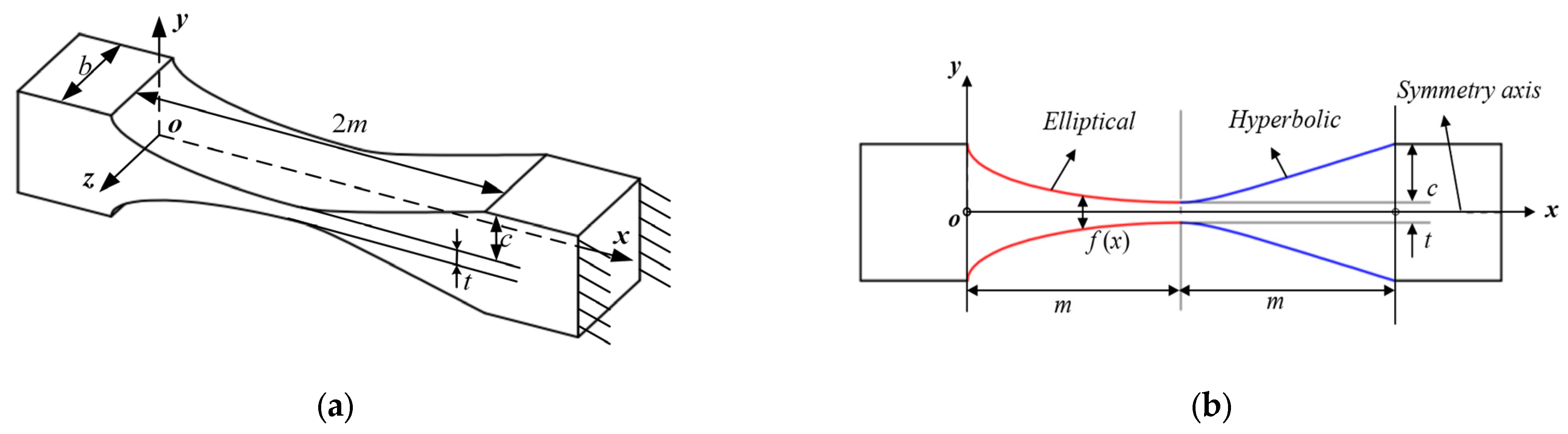
For hybrid flexure hinges with lateral asymmetry, the compliance will change when the fixed and free ends are exchanged. When the elliptical flexure hinge is the fixed end and the hyperbolic flexure hinge is the free end, it is called the elliptical–hyperbolic flexure hinge (EH) in Figure 1. Conversely, it is called the hyperbolic–elliptical flexure hinge (HE) in Figure 2. The long semiaxis of the elliptical portion is equal to the length of the hyperbolic portion; the intersection points of the ellipse and hyperbola serve as the vertex of the hyperbola; the elliptical portion is a quarter ellipse. In the figure, b, t, and L are the width, minimum thickness, and length of the hinge, respectively, and L = 2m; the remaining structural parameters include the length of the long semiaxis of the ellipse m, the length of the short semiaxis c, and the cutting depth of the hyperbolic portion c. The thickness at any point on the cross-section is f(x).
The following assumptions are made in the derivation of relevant formulas for the flexure hinge, as listed in [12]:
- (1)
- Based on the assumption of a small-deformation cantilever beam, the influence due to shear is ignored;
- (2)
- Hinge deformations are mostly generated in the elliptic and hyperbolic parts, while the deformation of other parts is neglected;
- (3)
- The coupling effect of deformation between hinges is neglected because the actual deformation generated by the hinges is small.
Based on these assumptions, the right end is assumed to be fixed entirely. The rotational moment Mz1 and the forces Fx1 and Fy1 are applied to the left end, as shown in Figure 3. Point O represents the origin of the coordinates and point 2 represents the center of rotation. Mz1 and Fy1 make the hybrid flexure hinge produce a small angular displacement θz that rotates about the z-axis; y1 denotes a small linear displacement along the y-axis under the action of Fy1 and Mz1; x1 denotes a small linear displacement along the x-axis under the action of Fx1.
The displacement–load matrix relationship [13] at point 1 is
where Ci,j is compliance, i denotes displacement, and j denotes load, according to the reciprocal theorem, Cθz, Fy1 = Cy1, Mz1.
The expression of displacement can also be
According to the energy method, the deformation energy U is
From Equations (1)–(3), the compliance equation for each direction of the hinge is
2.1.1. Elliptical–Hyperbolic Flexure Hinges
For EH, the continuous function form of any section thickness f(x) is
Substituting Equation (5) into Equation (4), the expressions for N1–N4 in each compliance term are as follows:
The direct integral solution to Equation (6) is too complicated due to the process. To simplify the amount of calculation, the elliptical and hyperbolic integral variables are selected as follows. For the elliptical flexure segments, the eccentric angle φ is introduced as the integrating variable, where x can be expressed as x = m + msinφ, and the corresponding differential is dx = mcosφ, let n = c/t. Since the elliptic part is a quarter ellipse, the integration interval is [−π/2,0], and t(x) can be obtained:
For the hyperbolic flexure segments, define x = m{1 + β/(1 + 2β)1/2tanθ} and β = t/2c, then dx = mβ/(1 + 2β)1/2sec2θdθ, the integration interval is [0, θm], θm = arctan{(1 + 2β)1/2/β}, and t(θ) can be obtained.
For the elliptical flexure segments, a new integral variable is used for the integral. Substituting Equation (7) into Equation (6), – can be obtained:
The expressions of G1–G4 are as follows:
For the hyperbolic flexure segments, substituting Equation (8) into Equation (6), – can be obtained:
2.1.2. Hyperbolic–Elliptical Flexure Hinges
For HE, the continuous function form of any section thickness f(x) is
Substituting Equation (21) into Equation (4), the expressions for N1–N4 in each compliance term are as follows:
The solution process of Equation (22) is similar to that of Equation (6); – can be obtained:
The four integral factors from to can be calculated as:
2.2. Rotation Accuracy
When the external loads cause a bending moment on the flexure hinges, the hinge center will inevitably shift, which will directly affect the rotation accuracy. When the hybrid hinge rotates around the axis, the rotation accuracy can be characterized by the magnitude of compliance at the center of the hinge rotation (point 2 in Figure 3). The rotation center will be off the geometric center for a hybrid flexure hinge with lateral asymmetry, and the distance to the origin is
To obtain compliance at the rotation center, a set of zero-value forces Fx2 and Fy2 are applied at the rotation center point 2, shown in Figure 3. The displacement–load matrix relationship [13] at point 2 is
The expression of displacement can also be
The deformation energy is
Substituting Equation (34) into Equation (33), the expression for the displacement at point 2 is
From Equations (31)–(35), the rotary accuracy of the flexure hinge is obtained:
2.2.1. Elliptical–Hyperbolic Flexure Hinges
From Equation (31), the center of rotation is in the elliptic section for EH, and the distance to the origin is
Substituting Equation (37) into Equation (36), the calculation equation for the rotation accuracy is
where
For the convenience of integration, assume ; the expressions of M1–M4 are as follows:
2.2.2. Hyperbolic–Elliptical Flexure Hinges
From Equation (31), the center of rotation is in the elliptic section for HE, and the distance to the origin is
Substituting Equation (44) into Equation (36), the calculation equation for the rotation accuracy is
The solution process of Equation (45) is similar to that of Equation (39); – can be obtained:
2.3. Maximum Stress
When notched flexure hinges deform, the change in geometry at the notch can easily lead to stress concentration and reduce their fatigue strength. The stress level of the hinges needs to be assessed to ensure the proper use of the flexure hinge [29]. The maximum stress of the hinge is principally caused by two parts, axial force and bending moment when the stress due to shear force is ignored. The maximum stress due to force Fx1 induced at the notch region is
The maximum stress due to moment Mz1 and force Fy1 at the notch region is
The coefficient of stress concentration ka and kb in Equations (47) and (48) are shown in reference books, for example, Pilkey [30] and Young [31]. The equation for calculating kb is
where B = 2c + t in Equation (49). Since the maximum stresses generally occur near the thinnest part of the flexure hinge and the curvature of the bottom curve of the notch is not the same everywhere, for the hybrid flexure hinge, the stress concentration coefficient of these two curves at the intersection should be calculated separately and then the average taken as the stress concentration coefficient of the hybrid flexure hinge. The stresses due to axial forces have smaller values than those due to bending. Therefore, only the stress due to bending is calculated in this case.
3. Verification of Theoretical Equations
3.1. Finite Element Verification
The FEA is carried out to validate the correctness of the equations derived from compliance, rotation accuracy, and maximum stress. Aluminum alloy is used in the calculation and analysis with material parameters E = 71Gpa and μ = 0.33. Twelve sets of different structural parameters are selected, as indicated in Table 1, and the width of all flexure hinges is 10 mm. Solid 187 element-type is selected to build the finite element model of the hybrid flexure hinge. Solid 187 is a tetrahedral element consisting of ten nodes; each node has three degrees of freedom. Mesh refinement is applied to the notch region of the hinge, with a mesh size not less than one-sixth of the minimum thickness of the hinge. Figure 4 shows the finite element model of the hyperbolic–elliptical hybrid flexure hinge for No. 7, which contains 67695 elements and 117163 nodes. The flexure hinge was fixed at the right end and a unit force Fx, Fy, or a unit moment Mz was exerted at the free end in verifying the compliance and rotation accuracy, respectively. The maximum stress is verified with its applied load of Fy = 1 N and Mz = 0.01 N·m. Figure 5 shows the stress distribution diagram of the hyperbolic–elliptical hybrid flexure hinge for No. 7, and it is found that the stresses are highest at the weak point of the hinge notch.
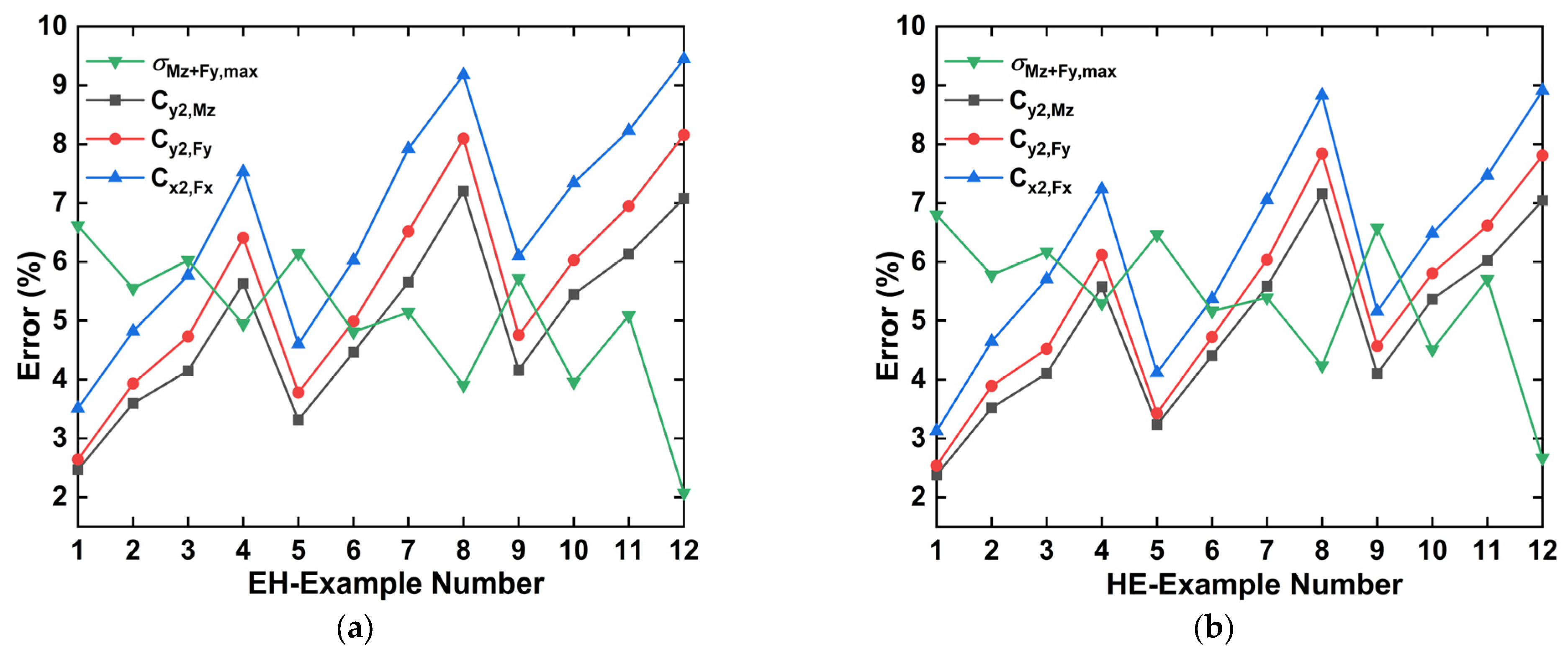
The analytical and FEA results of the compliance, rotation accuracy, and maximum stress of the hybrid flexure hinge are shown in Appendix A, Table A1 and Table A2. As can be seen in Figure 6 and Figure 7, the relative error between the analytical and finite element results is less than 10%. Based on the literature [12,13,14,15,16,17,18], the maximum relative error of the two is within 11%, thus verifying the accuracy of the theoretical derivation process and its results. Although the consistency of the theoretical calculation and FEA results meets the requirements, there are still errors, which mainly come from two aspects. One aspect is that when the theoretical analysis is made, the cantilever-beam-equivalent model of the flexure hinge is built based on a series of assumptions, such as ignoring the deformation outside the hinge, the coupling deformation between the microelements, and the effect of shear and torsion deformation, etc. Secondly, the hinge is a continuum in the finite element simulation. The FEA must first be discretized to approximate the calculation, resulting in discrete errors. In addition, to consider the accuracy and efficiency of the FEA, the size of the unit mesh may also introduce errors.
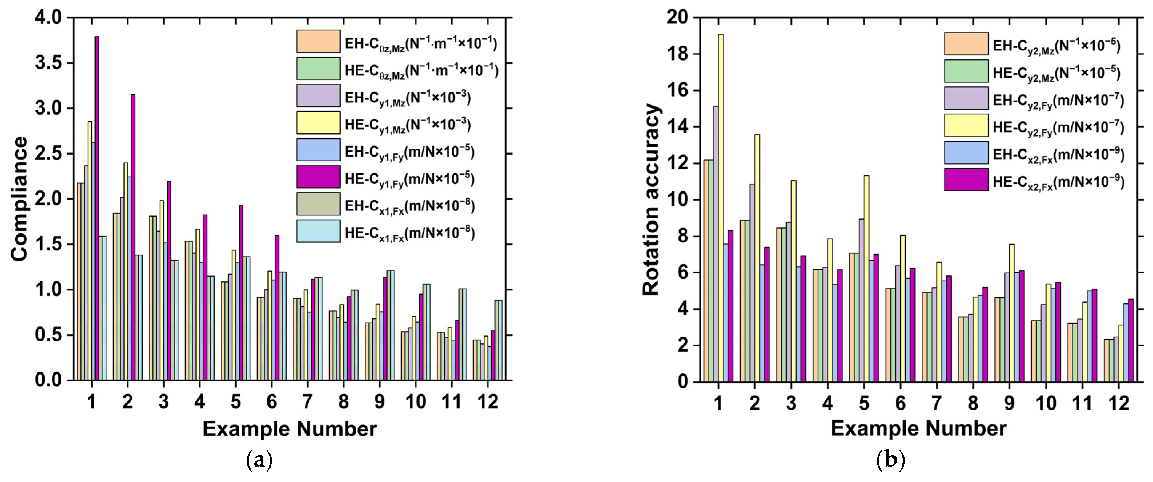
By analyzing the data in Figure 8, it can also be concluded that due to the longitudinal symmetry, the compliance Cθz−Mz and Cx1−Fx are the same for EH and HE, and the rotation accuracy Cy2−Mz is the same. However, due to the transverse asymmetry, when the free and fixed ends are swapped, the compliance and rotation accuracy change in the other directions, where EH is smaller than HE. For flexure hinges, having greater compliance in the rotational direction and greater stiffness in parasitic motion directions is an ideal design goal [32]. Therefore, EH is more suitable than HE for application in flexure support structures for fast steering mirrors.
3.2. Experimental Verification
The experimental method is used to verify the proposed compliance equation. The hinge material is 7075 aluminum alloy with E = 71 Gpa and μ = 0.33, and the slow wire electrical discharge wire cutting technology is used for processing. Experiments are conducted on two groups of hybrid flexure hinges, No. 4 and No. 8 in Table 1.
The experimental setup is shown in Figure 9. Cx1,Fx is very small and it is therefore difficult to measure the displacement of the center of the rigid body; only the equivalent compliance of Cθz,Mz, Cy1,Mz, and Cy1,Fy is tested. As shown in Figure 9a, in the first experiment, an equivalent moment Mz = Fx·L is generated by applying a force F to a point at a horizontal distance L from the center of the hinge. The corresponding displacement ∆Z is measured at the application point, ignoring the displacement caused by axial compression, to obtain Cθz,Mz = ∆Z·L2/F. To improve the accuracy of the experiment, seven groups of different loading masses from 50 g to 350 g are applied to obtain the results for Cθz,Mz.
In the second experiment (see Figure 9b), a force Fy is applied to the free end parallel to the axis of the hinge, which produces two components: a moment around the z-axis and a tension force in the y-direction, and the loading mass is the same as that in the first experiment. By employing the least squares method to perform data fitting on the results of experiments, the relationship between the measured load and displacement is shown in Figure 10, which can be obtained as the composite compliance of the hinge.
A comparison is made between the results obtained from the two experimental trials and those derived from analytical solutions, as shown in Table 2. The maximum errors are within 7% and 3%, respectively, which may come from the following aspects: (1) errors introduced by the material properties, (2) geometrical errors generated by processing and manufacturing, (3) systematic errors generated by the measurements, and (4) data processing errors.
4. Performance Analysis and Comparison
4.1. Influence of Structural Parameters on Compliance and Rotation Accuracy
In the design process of flexure hinges, a clear grasp of the relationship between structural parameters and their mechanical properties can help design more efficient hinges that meet performance requirements. According to the compliance calculation equation, Young’s modulus E and width b have a monotonically decreasing relationship with compliance, and the structural parameters t, m, and c of other hinges have a more complex effect on compliance. Any two parameters are assumed to vary within a reasonable range, taking the elliptical hyperbolic flexure hinge as an example, and the other parameters are fixed and unchanged. The relationship between compliance Cθz,Mz and rotation accuracy Cy2,Mz with parameters (c, m), (t, c), (t, m) is analyzed, as shown in Figure 11 and Figure 12. Other variation relations of compliance and slewing accuracy are similar to those of Cθz,Mz and Cy2,Mz.
As seen in Figure 11, the compliance increases with increasing m, decreases with increasing t and c, and the changing trend with t is relatively rapid. To improve the compliance of the flexure hinge, the minimum thickness should be reduced as the first technical means, but it should be noted that the stress concentration is more obvious while reducing the minimum thickness. Secondly, the compliance of flexure hinges can be improved by increasing the ratio of the short and long semiaxes of the ellipse. The compliance can also be improved by reducing the width of the hinge. As seen in Figure 12, the rotation accuracy decreases with increasing m and increases with t and c. It can be found that with the change in parameters, the trend in transformation of compliance and rotation accuracy is the opposite. The influence of structural parameters needs to be considered comprehensively in the design of flexure hinges to meet the needs of different applications, which also provides a theoretical basis for the further design optimization of the hinges.
4.2. Comparison of Compliance Accuracy Ratio
With the variation in parameters, the trends of compliance and rotation accuracy are the opposite. This means that increasing compliance by changing a single parameter will inevitably decrease rotary accuracy. To comprehensively consider the compliance and rotation accuracy, the ratio of the two is processed, and the introduction of the compliance accuracy ratio is used to assess the capability of the flexure hinge to maintain the rotation center position when the free end has the same displacement. The larger value of the compliance accuracy ratio denotes that the flexure hinge has improved ability to maintain the stability of the rotation center. The following are the definitions of different compliance accuracy ratios.
For the hybrid flexure hinge structure proposed in this paper, two kinds of flexure hinges, elliptical and hyperbolic, can be evolved under the limiting conditions of the parameters.
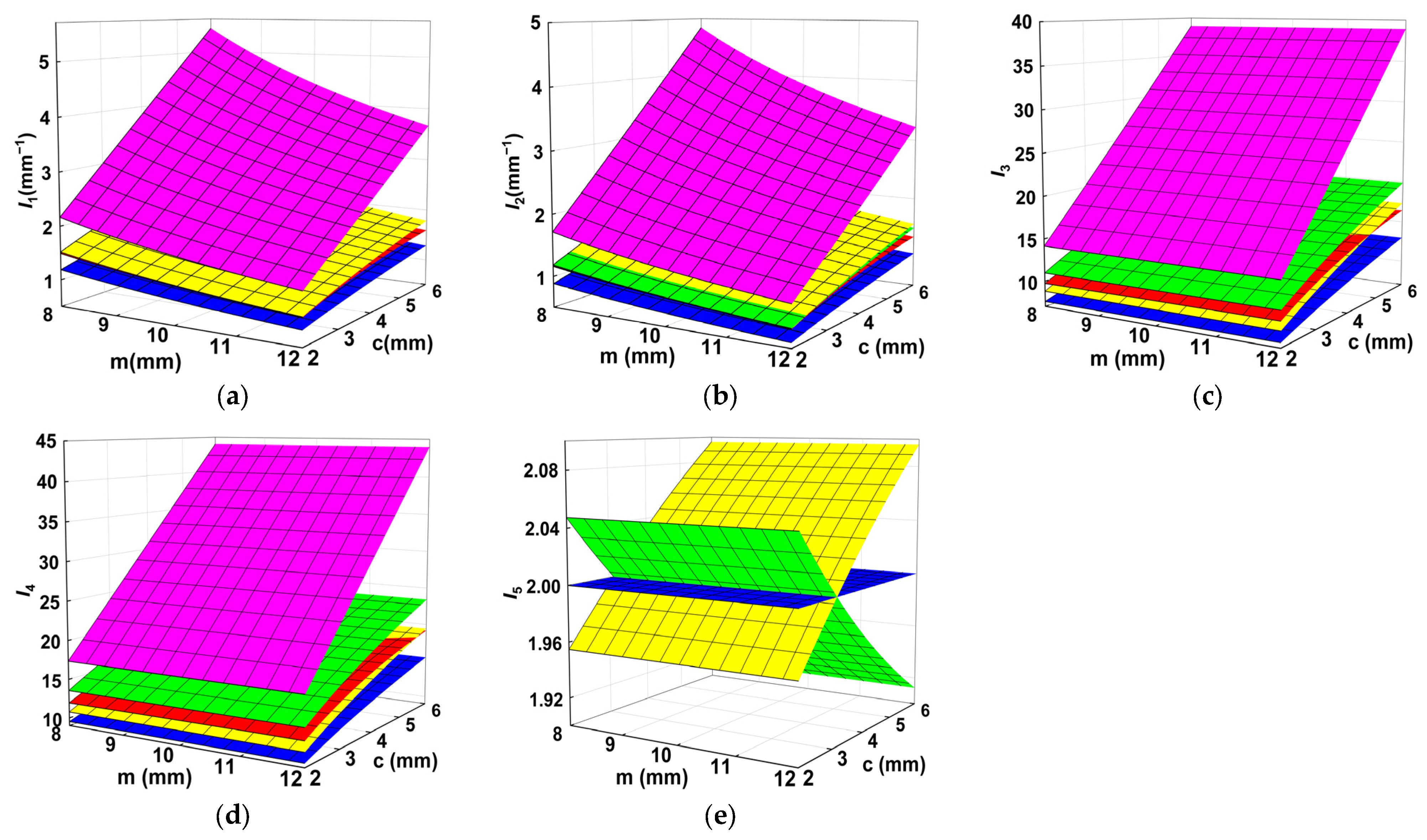
Circular flexure hinges [33] are also commonly used notched flexure hinges, and the performance of hinges is analyzed by comparing the flexure accuracy ratio of these five kinds of flexure hinges. The structural parameters t and b are 0.6 mm and 10 mm. The comparison of the rotation accuracy ratio is shown in Figure 13, from which the following characteristics can be obtained:
- (1)
- I1 and I2 show a nonlinear decreasing trend with increasing m or decreasing c, where the parameter c has a greater effect than m. I3 and I4 show a nonlinear increasing trend with increasing c and an almost constant trend with m. I5 remains essentially unchanged, except for EH and HE. It is shown that the elliptical hyperbolic flexure hinge under the premise of ensuring strength, the smaller the ratio of the long and short half-axis of the ellipse, the better the ability of the hinge to maintain the stability of the center of rotation.
- (2)
- A larger value of I1 indicates that the smaller the center of rotation deviates along the y-axis when the flexure hinges are subjected to the same rotational angle under the influence of moment Mz, and the better the ability to maintain the position of the rotation center. For I1, from greatest to least: hyperbolic, EH = HE, circular, and elliptical hinges.
- (3)
- A larger value of I2 indicates that the smaller the center of rotation deviates along the y-axis when the flexure hinges are subjected to the same rotational angle under the influence of force Fy. For I2, from greatest to least: hyperbolic, EH intersects with HE, circular, and elliptical hinges. When c > 2.5, EH performs better than HE.
- (4)
- A larger value of I3 indicates that the smaller the center of rotation deviates along the y-axis when the force Fy causes the flexure hinges to produce the same movement along the y-axis. For I3, from greatest to least, hyperbolic, HE, and EH intersect with the circular and elliptical hinges. When c > 5, EH performs better than circular hinges.
- (5)
- A larger value of I4 indicates that the smaller the center of rotation deviates along the y-axis when the flexure hinges are subjected to the same displacement along the y-axis under the influence of moment Mz. For I4, from greatest to least: hyperbolic, HE, EH intersecting with circular and elliptical hinges. When c > 5.5, EH performs better than circular hinges.
- (6)
- A larger value of I5 indicates that the smaller the center of rotation deviates along the x-axis when the force Fx causes the flexure hinges to produce the same movement along the x-axis. All three symmetric notched flexure hinges, hyperbolic, circular, and elliptical, have a value of 2. When c > 3, EH performs better than HE.
4.3. Comparison of Flexure Stress Ratios
Compliance can be quantitatively expressed as the displacement caused by the unit force. The ratio of compliance to maximum stress is defined as the compliance stress ratio. The larger the compliance stress ratio, the relatively smaller the deformation of the flexure hinge under the same external load, indicating that the flexure hinge is more capable of working in a low-stress condition. The compliance stress ratio is
The comparison of the compliance stress ratios for the five kinds of flexure hinges in Figure 14 indicates that the compliance stress ratios increase nonlinearly with increasing m or decreasing c. For the compliance stress ratio, from greatest to least: elliptical, EH (HE), circular, and hyperbolic. When m is close to 12 mm, and c is close to 2 mm, the compliance stress ratios of circular and EH (HE) are very close to each other.
Based on these analysis results of the compliance accuracy ratio and the compliance stress ratio, it is found that the compliance accuracy ratio of the elliptical hinge is the smallest, the compliance stress ratio is the largest, and the hyperbolic hinge is exactly the opposite, while EH (HE) is between the two, indicating that EH (HE) has well-balanced performance in compliance, rotation accuracy and low stress, which combines the respective advantages of the elliptical and hyperbolic hinges. The compliance accuracy ratio of EH (HE) to circular hinges varies with the change in structural parameters. The appropriate structural parameters can be selected according to different application requirements.
5. Conclusions
This article proposes a new hybrid flexure hinge consisting of semielliptical and semihyperbolic structures. It derives equations for the compliance, rotation accuracy, and maximum stress of the hybrid flexure hinge, and the FEA and experimental verification are carried out. The effects of different parameters on the compliance and rotation accuracy of the hinge are discussed. The comprehensive performance of other flexure hinges is evaluated from the compliance accuracy ratio and compliance stress ratio. The following conclusions can be obtained:
For hybrid flexure hinges with longitudinal symmetry and lateral asymmetry, the compliance Cθz,Mz, Cx,Fx, and accuracy Cy2,Mz are unchanged due to longitudinal symmetry when the free and fixed ends are swapped. This provides a valuable reference for designing the hybrid flexible hinge in terms of selecting the fixed end and free end.
The consistency between analytical and FEA results is over 90%. The consistency with the experimental results is over 93%, which verifies the correctness of the derived equation. In the experiment, a linear correlation exists between the displacement of the flexure hinge and the load.
The compliance increases with increasing parameter m or decreasing parameters b, t, and c. With the change in parameters, the changing trend in compliance and rotation accuracy is the opposite. Changing a single parameter makes compliance increase, but this increase leads to a reduction in rotation accuracy. The most effective approach to increase compliance is to lower the minimum thickness. Reducing the width of the hinge can also improve the size of compliance, and its capability in maintaining the center of the rotation position remains unchanged.
The proposed compliance stress ratio provides a basis for quantitatively comparing the comprehensive performance of flexure hinges. Comparing the compliance accuracy ratio and compliance stress ratio of the hybrid flexure hinge with the elliptical, hyperbolic, and circular flexure hinges, it can be seen that its compliance accuracy ratio is higher than that of the elliptical, and its compliance stress ratio is higher than that of the hyperbolic and circular hinges. This indicates that the hybrid flexure hinge combines the advantages of large compliance and low-stress level of the elliptical hinge and the high rotation accuracy of the hyperbolic hinge, which is superior in comprehensive performance.
In summary, the elliptical hyperbolic hybrid flexure hinge designed in this paper is suitable for the support structure of fast steering mirror systems. Furthermore, it provides a solid theoretical foundation for the further optimization of hybrid flexure hinges. Future work will build on this paper to carry out fatigue life analysis of flexure hinges and structural design studies of fast steering mirrors for satellite-borne laser communications.
Author Contributions
Y.W., writing—original draft; L.Z., writing—review and editing (equal); L.M., writing—review and editing (equal); H.L., writing—review and editing (equal); Y.M., writing—review and editing (equal). All authors have read and agreed to the published version of the manuscript.
Funding
This research was funded by the National Natural Science of China, grant number U2141231.
Data Availability Statement
The data that support the findings of this study are available from the corresponding author upon reasonable request.
Conflicts of Interest
The authors declare no conflicts of interest.
Nomenclature
| b | cross-sectional flexure width |
| c | stress concentration factor |
| k | stress concentration factor |
| m | length of the long semiaxis of the ellipse |
| n | nondimensional parameter |
| t | minimum thickness of flexure |
| x, y, z | reference axes, deflections |
| A | cross-sectional flexure area |
| C | compliance |
| E | Young’s modulus |
| F | force |
| I | compliance accuracy ratio |
| L | length of the flexure |
| M | bending moment |
| U | elastic strain energy |
| Greek letters | |
| β | nondimensional parameters |
| γ | stress ratio |
| θ | rotation angle along the z-axis |
| μ | Poisson’s ratio |
| ρ | curvature radius |
| σ | stress |
| Subscripts | |
| Fx, Fy | force along the x, y axes |
| M | bending moment |
| e | elliptical |
| eh | elliptical–hyperbolic flexure |
| h | hyperbolic |
| he | hyperbolic–elliptical flexure |
| max | maximum |
| r | rotation center |
| x, y, z | reference axes |
| θz | rotation angle along the z-axis |
| Superscripts | |
| ′ | refers to the rotation center |
Appendix A

Table A1.
Comparison of compliance analytical (A) and FEA (F) results for EH and HE.
| Sample No. | Cθz−Mz (N−1·m−1 × 10⁻¹) | Cy1−Mz (N−1 × 10⁻³) | Cy1−Fy (m/N × 10−5) | Cx1−Fx (m/N × 10−8) | ||||
|---|---|---|---|---|---|---|---|---|
| EH | HE | EH | HE | EH | HE | EH | HE | |
| 1A | 2.174 | 2.174 | 2.365 | 2.853 | 2.622 | 3.793 | 1.589 | 1.589 |
| 1F | 2.217 | 2.218 | 2.417 | 2.905 | 2.685 | 3.863 | 1.633 | 1.634 |
| 2A | 1.840 | 1.840 | 2.018 | 2.397 | 2.245 | 3.155 | 1.382 | 1.382 |
| 2F | 1.893 | 1.893 | 2.082 | 2.461 | 2.319 | 3.238 | 1.444 | 1.443 |
| 3A | 1.812 | 1.812 | 1.642 | 1.981 | 1.517 | 2.195 | 1.324 | 1.324 |
| 3F | 1.889 | 1.889 | 1.719 | 2.059 | 1.586 | 2.281 | 1.394 | 1.395 |
| 4A | 1.533 | 1.533 | 1.402 | 1.665 | 1.299 | 1.826 | 1.151 | 1.151 |
| 4F | 1.608 | 1.609 | 1.470 | 1.753 | 1.365 | 1.922 | 1.230 | 1.231 |
| 5A | 1.085 | 1.085 | 1.171 | 1.433 | 1.297 | 1.926 | 1.365 | 1.365 |
| 5F | 1.119 | 1.119 | 1.209 | 1.477 | 1.342 | 1.987 | 1.432 | 1.433 |
| 6A | 0.917 | 0.917 | 0.998 | 1.203 | 1.106 | 1.600 | 1.192 | 1.192 |
| 6F | 0.956 | 0.956 | 1.042 | 1.253 | 1.158 | 1.666 | 1.255 | 1.255 |
| 7A | 0.904 | 0.904 | 0.813 | 0.995 | 0.751 | 1.114 | 1.137 | 1.137 |
| 7F | 0.953 | 0.954 | 0.858 | 1.049 | 0.794 | 1.175 | 1.214 | 1.214 |
| 8A | 0.764 | 0.764 | 0.693 | 0.836 | 0.640 | 0.926 | 0.993 | 0.993 |
| 8F | 0.820 | 0.820 | 0.746 | 0.894 | 0.691 | 0.991 | 1.081 | 1.080 |
| 9A | 0.633 | 0.633 | 0.680 | 0.840 | 0.754 | 1.139 | 1.209 | 1.209 |
| 9F | 0.659 | 0.659 | 0.705 | 0.876 | 0.784 | 1.189 | 1.263 | 1.262 |
| 10A | 0.535 | 0.535 | 0.578 | 0.706 | 0.641 | 0.950 | 1.060 | 1.060 |
| 10F | 0.564 | 0.564 | 0.609 | 0.744 | 0.677 | 0.998 | 1.129 | 1.128 |
| 11A | 0.528 | 0.528 | 0.472 | 0.583 | 0.436 | 0.659 | 1.008 | 1.008 |
| 11F | 0.561 | 0.560 | 0.499 | 0.622 | 0.463 | 0.704 | 1.081 | 1.081 |
| 12A | 0.446 | 0.446 | 0.402 | 0.490 | 0.371 | 0.547 | 0.883 | 0.883 |
| 12F | 0.480 | 0.480 | 0.432 | 0.528 | 0.401 | 0.591 | 0.963 | 0.962 |
Table A2.
Comparison of rotation accuracy and maximum stress analytical (A) and FEA (F) results for EH and HE.
Table A2.
Comparison of rotation accuracy and maximum stress analytical (A) and FEA (F) results for EH and HE.
| Sample No. | Cy2−Mz (N−1 × 10⁻⁵) | Cy2−Fy (m/N × 10−7) | Cx2−Fx (m/N × 10−9) | σMz+Fy,max (Mpa) | kb | ||||
|---|---|---|---|---|---|---|---|---|---|
| EH | HE | EH | HE | EH | HE | EH | HE | EH = HE | |
| 1A | 12.178 | 12.178 | 15.118 | 19.074 | 7.579 | 8.308 | 38.69 | 38.69 | 1.055 |
| 1F | 12.486 | 12.475 | 15.528 | 19.571 | 7.855 | 8.576 | 36.13 | 36.06 | |
| 2A | 8.874 | 8.874 | 10.857 | 13.575 | 6.431 | 7.385 | 39.82 | 39.82 | 1.086 |
| 2F | 9.205 | 9.198 | 11.301 | 14.125 | 6.757 | 7.745 | 37.61 | 37.52 | |
| 3A | 8.457 | 8.457 | 8.749 | 11.038 | 6.316 | 6.923 | 35.82 | 35.82 | 1.075 |
| 3F | 8.823 | 8.819 | 9.183 | 11.561 | 6.703 | 7.342 | 33.66 | 33.61 | |
| 4A | 6.163 | 6.163 | 6.283 | 7.856 | 5.359 | 6.154 | 37.21 | 37.21 | 1.116 |
| 4F | 6.531 | 6.527 | 6.713 | 8.368 | 5.796 | 6.634 | 35.37 | 35.24 | |
| 5A | 7.060 | 7.060 | 8.938 | 11.325 | 6.659 | 6.989 | 21.81 | 21.81 | 1.057 |
| 5F | 7.302 | 7.296 | 9.289 | 11.727 | 6.980 | 7.289 | 20.47 | 20.40 | |
| 6A | 5.138 | 5.138 | 6.378 | 8.047 | 5.684 | 6.231 | 22.46 | 22.46 | 1.089 |
| 6F | 5.378 | 5.375 | 6.713 | 8.446 | 6.048 | 6.585 | 21.38 | 21.30 | |
| 7A | 4.903 | 4.903 | 5.172 | 6.554 | 5.549 | 5.825 | 20.21 | 20.21 | 1.078 |
| 7F | 5.197 | 5.193 | 5.534 | 6.975 | 6.026 | 6.267 | 19.17 | 19.12 | |
| 8A | 3.568 | 3.568 | 3.691 | 4.657 | 4.737 | 5.192 | 21.01 | 21.01 | 1.120 |
| 8F | 3.845 | 3.843 | 4.016 | 5.053 | 5.216 | 5.669 | 20.19 | 20.12 | |
| 9A | 4.627 | 4.627 | 5.971 | 7.561 | 5.993 | 6.100 | 13.99 | 13.99 | 1.060 |
| 9F | 4.828 | 4.825 | 6.269 | 7.923 | 6.382 | 6.432 | 13.19 | 13.07 | |
| 10A | 3.366 | 3.366 | 4.240 | 5.370 | 5.144 | 5.451 | 14.41 | 14.41 | 1.092 |
| 10F | 3.560 | 3.557 | 4.512 | 5.701 | 5.552 | 5.829 | 13.84 | 13.76 | |
| 11A | 3.213 | 3.213 | 3.455 | 4.375 | 4.994 | 5.084 | 12.97 | 12.97 | 1.081 |
| 11F | 3.423 | 3.419 | 3.713 | 4.685 | 5.442 | 5.502 | 12.31 | 12.23 | |
| 12A | 2.337 | 2.337 | 2.454 | 3.108 | 4.287 | 4.542 | 13.49 | 13.49 | 1.124 |
| 12F | 2.515 | 2.514 | 2.672 | 3.375 | 4.734 | 4.954 | 13.21 | 13.13 | |
References
- Howell, L.L. Compliant Mechanisms; John Wiley and Sons, Inc.: New York, NY, USA, 2001. [Google Scholar]
- Iandiorio, C.; Salvini, P. Elasto-Kinematics and Instantaneous Invariants of Compliant Mechanisms Based on Flexure Hinges. Micromachines 2023, 14, 783. [Google Scholar] [CrossRef] [PubMed]
- Lu, Y.; Fan, D.; Zhang, Z. Theoretical and experimental determination of bandwidth for a two-axis fast steering mirror. Optik 2013, 124, 2443–2449. [Google Scholar] [CrossRef]
- Zhao, L.; Wang, H.; Duan, W.; Wang, P.; Wu, Q.; Wang, X. Design and analysis of a bi-axial centralized butterfly flexure hinge for fast steering mirrors. J. Astron. Telesc. Instrum. Syst. 2020, 6, 048003. [Google Scholar] [CrossRef]
- Li, Z.; Su, Z.; Zhao, L.; Han, H.; Guo, Z.; Zhao, Y.; Sun, H. Design and locomotion study of stick-slip piezoelectric actuator using two-stage flexible hinge structure. Micromachines 2021, 12, 154. [Google Scholar] [CrossRef]
- Ding, B.; Yang, Z.-X.; Xiao, X.; Zhang, G. Design of reconfigurable planar micro-positioning stages based on function modules. IEEE Access 2019, 7, 15102–15112. [Google Scholar] [CrossRef]
- Šalinić, S.; Nikolić, A. A new pseudo-rigid-body model approach for modeling the quasi-static response of planar flexure-hinge mechanisms. Mech. Mach. Theory 2018, 124, 150–161. [Google Scholar] [CrossRef]
- Ma, N.; Monk, S.; Cheneler, D. Modelling and Analysis of the Spital Branched Flexure-Hinge Adjustable-Stiffness Continuum Robot. Robotics 2022, 11, 97. [Google Scholar] [CrossRef]
- Paros, J.M.; Weisbord, L. How to design flexure hinges. Mach. Des. 1965, 37, 151–157. [Google Scholar]
- Smith, S.T.; Badami, V.G.; Dale, J.S.; Xu, Y. Elliptical flexure hinges. Rev. Sci. Instrum. 1997, 68, 1474–1483. [Google Scholar] [CrossRef]
- Lobontiu, N.; Paine, J.S.; Garcia, E.; Goldfarb, M. Corner-filleted flexure hinges. J. Mech. Des. 2001, 123, 346–352. [Google Scholar] [CrossRef]
- Lobontiu, N.; Paine, J.S.; O’Malley, E.; Samuelson, M. Parabolic and hyperbolic flexure hinges: Flexibility, motion precision and stress characterization based on compliance closed-form equations. Precis. Eng. 2002, 26, 183–192. [Google Scholar] [CrossRef]
- Lobontiu, N.; Paine, J.S.; Garcia, E.; Goldfarb, M. Design of symmetric conic-section flexure hinges based on closed-form compliance equations. Mech. Mach. Theory 2002, 37, 477–498. [Google Scholar] [CrossRef]
- Chen, G.; Liu, X.; Gao, H.; Jia, J. A generalized model for conic flexure hinges. Rev. Sci. Instrum. 2009, 80, 055106. [Google Scholar] [CrossRef]
- Chen, G.; Liu, X.; Du, Y. Elliptical-arc-fillet flexure hinges: Toward a generalized model for commonly used flexure hinges. J. Mech. Des. 2011, 133, 081002. [Google Scholar] [CrossRef]
- Xu, N.; Dai, M.; Zhou, X. Analysis and design of symmetric notch flexure hinges. Adv. Mech. Eng. 2017, 9, 1–12. [Google Scholar] [CrossRef]
- Tian, Y.; Shirinzadeh, B.; Zhang, D. Closed-form compliance equations of filleted V-shaped flexure hinges for compliant mechanism design. Precis. Eng. 2010, 34, 408–418. [Google Scholar] [CrossRef]
- Kong, J.; Huang, Z.; Xian, X.; Wang, Y.; Yu, P. Generalized model for conic-V-shaped flexure hinges. Sci. Prog. 2020, 103, 1–26. [Google Scholar] [CrossRef]
- Tian, Y.; Shirinzadeh, B.; Zhang, D.; Zhong, Y. Three flexure hinges for compliant mechanism designs based on dimensionless graph analysis. Precis. Eng. 2010, 34, 92–100. [Google Scholar] [CrossRef]
- Li, Q.; Pan, C.; Xu, X. Closed-form compliance equations for power-function-shaped flexure hinge based on unit-load method. Precis. Eng. 2013, 37, 135–145. [Google Scholar] [CrossRef]
- Liang, J.; Li, R.; Bai, S.; Li, Q.; Fengping, N.; Shuhua, K. Compliance and fatigue life analysis of U-shaped flexure hinge. Mechanika 2019, 25, 501–510. [Google Scholar] [CrossRef]
- Valentini, P.P.; Pennestrì, E. Second-order approximation pseudo-rigid model of leaf flexure hinge. Mech. Mach. Theory 2017, 116, 352–359. [Google Scholar] [CrossRef]
- Chen, G.; Jia, J.; Li, Z. On hybrid flexure hinges. In Proceedings of the 2005 IEEE Networking, Sensing and Control, Tucson, AZ, USA, 19–22 March 2005; pp. 700–704. [Google Scholar]
- Chen, G.; Jia, J.; Li, Z. Right-circular corner-filleted flexure hinges. In Proceedings of the IEEE International Conference on Automation Science and Engineering, Edmonton, AB, Canada, 1–2 August 2005; pp. 249–253. [Google Scholar]
- Lin, R.; Zhang, X.; Long, X.; Fatikow, S. Hybrid flexure hinges. Rev. Sci. Instrum. 2013, 84, 085004. [Google Scholar] [CrossRef]
- Wang, R.; Zhou, X.; Zhu, Z.; Liu, Q. Development of a novel type of hybrid non-symmetric flexure hinges. Rev. Sci. Instrum. 2015, 86, 085003. [Google Scholar] [CrossRef] [PubMed]
- Wang, R.; Zhou, X.; Zhu, Z. Development of a novel sort of exponent-sine-shaped flexure hinges. Rev. Sci. Instrum. 2013, 84, 095008. [Google Scholar] [CrossRef] [PubMed]
- Fu, J.; Yan, C.; Liu, W.; Yuan, T. Simplified equations of the compliant matrix for right elliptical flexure hinges. Rev. Sci. Instrum. 2015, 86, 115115. [Google Scholar] [CrossRef] [PubMed]
- Wang, J.; Liu, X. Generalized equations for estimating stress concentration factors of various notch flexure hinges. J. Mech. Des. 2014, 136, 031009. [Google Scholar] [CrossRef]
- Pilkey, W.D.; Pilkey, D.F.; Bi, Z. Peterson’s Stress Concentration Factors, 4th ed.; John Wiley and Sons, Inc.: New York, NY, USA, 2020; pp. 90–92. [Google Scholar]
- Young, W.C.; Budynas, R.G.; Sadegh, A.M. Roark’s Formulas for Stress and Strain, 8th ed.; McGraw-Hill Education: New York, NY, USA, 2012; pp. 801–822. [Google Scholar]
- Liu, M.; Zhang, X.; Fatikow, S. Design and analysis of a multi-notched flexure hinge for compliant mechanisms. Precis. Eng. 2017, 48, 292–304. [Google Scholar] [CrossRef]
- Wu, Y.; Zhou, Z. Design calculations for flexure hinges. Rev. Sci. Instrum. 2002, 73, 3101–3106. [Google Scholar] [CrossRef]
Figure 1.
Elliptical–hyperbolic flexure hinge: (a) three-dimensional view; (b) front view with main parameters.
Figure 1.
Elliptical–hyperbolic flexure hinge: (a) three-dimensional view; (b) front view with main parameters.

Figure 2.
Hyperbolic–elliptical flexure hinge: (a) three-dimensional view; (b) front view with main parameters.
Figure 2.
Hyperbolic–elliptical flexure hinge: (a) three-dimensional view; (b) front view with main parameters.

Figure 3.
Force analysis diagram of the hybrid flexure hinge.

Figure 4.
Finite element model of HE for No. 7.

Figure 5.
Stress distribution of HE for No. 7.

Figure 6.
Errors between analytical (A) and FEA (F) results of compliance for EH and HE: (a) EH; (b) HE. Note: error = 1 − A/F.
Figure 6.
Errors between analytical (A) and FEA (F) results of compliance for EH and HE: (a) EH; (b) HE. Note: error = 1 − A/F.

Figure 7.
Errors between analytical (A) and FEA (F) results of rotation accuracy and maximum stress for EH and HE: (a) EH; (b) HE. Note: error = 1 − A/F.
Figure 7.
Errors between analytical (A) and FEA (F) results of rotation accuracy and maximum stress for EH and HE: (a) EH; (b) HE. Note: error = 1 − A/F.

Figure 8.
Comparison of analytical results of compliance and rotation accuracy for EH and HE: (a) compliance; (b) rotation accuracy.
Figure 8.
Comparison of analytical results of compliance and rotation accuracy for EH and HE: (a) compliance; (b) rotation accuracy.

Figure 9.
The experimental setups: (a) evaluation setup for Cθz,Mz; (b) evaluation setup for Cy1,Mz and Cy1,Fy equivalent compliance.
Figure 9.
The experimental setups: (a) evaluation setup for Cθz,Mz; (b) evaluation setup for Cy1,Mz and Cy1,Fy equivalent compliance.

Figure 10.
The relationship between load and displacement.

Figure 11.
Influence of geometric parameters on compliance: (a) Cθz, Mz versus structural parameters c and m; (b) Cθz,Mz versus structural parameters t and c; (c) Cθz,Mz versus structural parameters t and m.
Figure 11.
Influence of geometric parameters on compliance: (a) Cθz, Mz versus structural parameters c and m; (b) Cθz,Mz versus structural parameters t and c; (c) Cθz,Mz versus structural parameters t and m.

Figure 12.
Influence of geometric parameters on rotation accuracy: (a) Cy2,Mz versus structural parameters c and m; (b) Cy2,Mz versus structural parameters t and c; (c) Cy2,Mz versus structural parameters t and m.
Figure 12.
Influence of geometric parameters on rotation accuracy: (a) Cy2,Mz versus structural parameters c and m; (b) Cy2,Mz versus structural parameters t and c; (c) Cy2,Mz versus structural parameters t and m.

Figure 13.
Comparison of the accuracy factors with parameter m and c: (a) I1, (b) I2, (c) I3, (d) I4, (e) I5. Note: yellow surface, EH; green surface, HE; blue surface, elliptical; magenta surface, hyperbolic; and red surface, circular.
Figure 13.
Comparison of the accuracy factors with parameter m and c: (a) I1, (b) I2, (c) I3, (d) I4, (e) I5. Note: yellow surface, EH; green surface, HE; blue surface, elliptical; magenta surface, hyperbolic; and red surface, circular.

Figure 14.
Comparison of the flexure stress ratio with parameters m and c. Note: yellow surface, EH; blue surface, elliptical; magenta surface, hyperbolic; and red surface, circular.
Figure 14.
Comparison of the flexure stress ratio with parameters m and c. Note: yellow surface, EH; blue surface, elliptical; magenta surface, hyperbolic; and red surface, circular.

Table 1.
Simulation of structural parameters of flexure hinges.
| Sample No. | t (mm) | m (mm) | c (mm) |
|---|---|---|---|
| 1 | 0.6 | 12 | 6 |
| 2 | 0.6 | 12 | 8 |
| 3 | 0.6 | 10 | 6 |
| 4 | 0.6 | 10 | 8 |
| 5 | 0.8 | 12 | 6 |
| 6 | 0.8 | 12 | 8 |
| 7 | 0.8 | 10 | 6 |
| 8 | 0.8 | 10 | 8 |
| 9 | 1.0 | 12 | 6 |
| 10 | 1.0 | 12 | 8 |
| 11 | 1.0 | 10 | 6 |
| 12 | 1.0 | 10 | 8 |
Table 2.
Comparisons of experiment (Ex) and analytical (An) results.
| Type | EH | HE | |||
|---|---|---|---|---|---|
| No. | 4 | 8 | 4 | 8 | |
| Cθz,Mz (N−1·m−1 × 10⁻¹) | An | 1.533 | 0.764 | 1.533 | 0.764 |
| Ex | 1.452 | 0.711 | 1.452 | 0.711 | |
| Err% | 5.28 | 6.94 | 5.28 | 6.94 | |
| Ceq (μm/N) | An | 20.002 | 9.865 | 26.585 | 13.442 |
| Ex | 20.357 | 9.571 | 27.357 | 13.214 | |
| Err% | −1.79 | 2.98 | −2.90 | 1.70 | |
Disclaimer/Publisher’s Note: The statements, opinions and data contained in all publications are solely those of the individual author(s) and contributor(s) and not of MDPI and/or the editor(s). MDPI and/or the editor(s) disclaim responsibility for any injury to people or property resulting from any ideas, methods, instructions or products referred to in the content. |
© 2024 by the authors. Licensee MDPI, Basel, Switzerland. This article is an open access article distributed under the terms and conditions of the Creative Commons Attribution (CC BY) license (https://creativecommons.org/licenses/by/4.0/).
Share and Cite
MDPI and ACS Style
Wang, Y.; Zhang, L.; Meng, L.; Lu, H.; Ma, Y. Theoretical Modeling and Experimental Verification of Elliptical Hyperbolic Hybrid Flexure Hinges. Symmetry 2024, 16, 345. https://0-doi-org.brum.beds.ac.uk/10.3390/sym16030345
AMA Style
Wang Y, Zhang L, Meng L, Lu H, Ma Y. Theoretical Modeling and Experimental Verification of Elliptical Hyperbolic Hybrid Flexure Hinges. Symmetry. 2024; 16(3):345. https://0-doi-org.brum.beds.ac.uk/10.3390/sym16030345
Chicago/Turabian StyleWang, Yan, Lizhong Zhang, Lixin Meng, Hongjie Lu, and Yongheng Ma. 2024. "Theoretical Modeling and Experimental Verification of Elliptical Hyperbolic Hybrid Flexure Hinges" Symmetry 16, no. 3: 345. https://0-doi-org.brum.beds.ac.uk/10.3390/sym16030345
Note that from the first issue of 2016, this journal uses article numbers instead of page numbers. See further details here.