Article

Reconstruction of 16th–17th Century Lead Smelting Processes on the Basis of Slag Properties: A Case Study from Sławków, Poland

by
Rafał Warchulski
1,*,
Monika Szczuka
2 and
Krzysztof Kupczak
1
1
Institute of Earth Sciences, Faculty of Natural Sciences, University of Silesia, Będzińska 60, 41-200 Sosnowiec, Poland
2
Department of General Geology and Geotourism, Faculty of Geology, Geophysics and Environmental Protection, AGH, Al. Mickiewicza 30, 30-059 Kraków, Poland
*
Author to whom correspondence should be addressed.
Submission received: 3 November 2020 / Revised: 18 November 2020 / Accepted: 19 November 2020 / Published: 20 November 2020
(This article belongs to the Special Issue Mineralogy, Trace Elements and Isotopic Tracers in Archaeometallurgy)

Abstract

:
The study focuses on the reconstruction of the technological process in the 16th–17th century lead smelter in Sławków based on chemical and petrographic analyzes of slags. There are three main types of material at the landfill: glassy, crystalline, and weathered. Glassy slags are made of amorphous phase in which crystals of pyroxene, willemite, olivine, wüstite, and lead oxide appear. Crystalline slags are composed of wollastonite, rankinite, melilite, anorthite, quartz, and Fe oxides. Weathered slags have a composition similar to glassy slags, but they also contain secondary phases: anglesite and cerussite. Chemical analyzes confirmed that the smelter used sulphide ores, which were roasted, and the main addition to the charge was quartz sand. The smelting process took place in a brick-built furnace, under reducing conditions, with varied oxygen fugacity ranging from WM to MH buffer. The slag characteristics show a knowledge of the workers in the field of smelting methods. The addition of SiO2 allowed for the binding of elements that could contaminate the obtained lead, and at the same time, the low melting point of the material (1150 °C) and the melt viscosity (logη = 1.34 for 1150 °C) was maintained, enabling the effective separation of liquid lead.

1. Introduction

Due to the ease of processing, a wide range of applications and the coexistence with silver, lead deposits have played an important role in historical times [1]. The oldest (from 7th–6th millennium BC) known center related to lead metallurgy is the Anatolian settlement of Catal Hüjük, where the remains of jewelry made of this metal have been preserved [2]. An impressive metallurgical complex from the Late Chalcolithic period (5th millennium BC) was discovered in a cave in the northern Negev desert (Israel) [3]. In this complex a biconical object made of pure metallic lead was found logged onto a wooden shaft [3]. In Europe, the oldest objects containing metallic lead are biconical vessels from Pietrele on the Lower Danube dated to ca. 4400–4300 BC [4]. In antiquity, lead compounds were commonly used, e.g., as dyes (red lead—Pb3O4; lead white—PbCO3) [2,5], cosmetics (e.g., mascara or lipstick in ancient Egypt (ZnS)) [1,2,5] and as alloy additives [6]. The ancient Romans began to use lead on an industrial scale, including for the construction of aqueducts [1,2]. In Rome, lead acetate was also widely used as a substance for improving the taste of wine [5,6], although this application of lead was invented by the Egyptians and the Greeks [7]. Later, lead began to be used for the production of shooting balls, printing inks, and toys (lead soldiers) [5]. Despite the knowledge about its harmfulness, lead is still a widely used metal nowadays. It is used in the production of sulfuric acid, in the construction industry, as well as in the production of batteries and nuclear reactors [5]. In the centers of the historical metallurgical industry, we can observe remnants of metallurgical activities in the form of slags. They are a research topic in Poland [8,9] and in other European countries [10,11,12,13,14].
Due to the presence of potentially toxic elements (PTEs) in slags, they are most often analyzed in terms of their impact on the environment [9,15,16]. Slag analysis also helps to understand the mechanism of the formation of mineral phases with an unusual chemical composition [17]. They are also used to understand geological processes, as they can be treated as analogs of natural rocks (e.g., paralavas, melilitolites) which are formed under similar pressure and temperature conditions [18]. Their commercial use is also widely researched [17,19,20]. Slags are often the only tool for the reconstruction of historical metallurgical processes [10,12,21].
During such reconstructions, the important sources of information are historical documents and production remains. Based on descriptions contained in such works as De Re Metallica, the methods and devices used for the production of metals can be reconstructed [22]. Production remains such as slags are significant because, in the absence of historical documents on their basis, it is possible to reconstruct the smelting conditions [10,12,13,23,24,25,26,27,28]. By analyzing their chemical and phase composition, we can recreate the conditions in the historical furnaces. One of them is temperature during smelting process. Geochemical, petrological and experimental methods can be used to approximate it. Numerous slag studies determined the smelting temperature based on phase diagrams [10,18,23,25,27], geothermometers [21,29,30], or laboratory experiments [8,18,31]. Other method require the construction of furnaces, similar to those used in historical times [11,12]. During smelting experiments in such, it is possible to measure the actual temperature inside the furnace [12]. It also allows the observation of the reactions taking place during the smelting [11,12]. Another factor that should be considered in the studies of historical smelting process is the melt viscosity [10,17,27,31,32]. Low melt viscosity facilitated the process of separating of the metallic phase from the slag, which makes the metallurgical process more effective [31]. Geochemical and petrological studies can also approximate the furnace atmosphere [31] and addition in the smelting process [8,24,32,33,34]. The charcoal fragments occasionally occurring in historical slags can be used to determine the type of wood used [12,28], and also by dendrochronological [35] and radiocarbon [12,28,35] methods to determine their age.
Little is known about the slag and smelting processes of the early modern period. The existing studies focus mainly on medieval (e.g., [11,12,14,24]) or contemporary times (e.g., [16,21,26]). It creates an almost 300-year (1500–1800) gap in the research on slags and metallurgical processes. This study aims to fill this gap by recreating the historic metallurgical process in the 16th–17th century lead smelter in Sławków. Process reconstruction is based on mineralogical and geochemical studies, taking into account the temperature in the furnace, the viscosity of the metallurgical melt, and the type of additives added to the ore. This research will allow for a better understanding of metal production in this period in Poland and Europe.

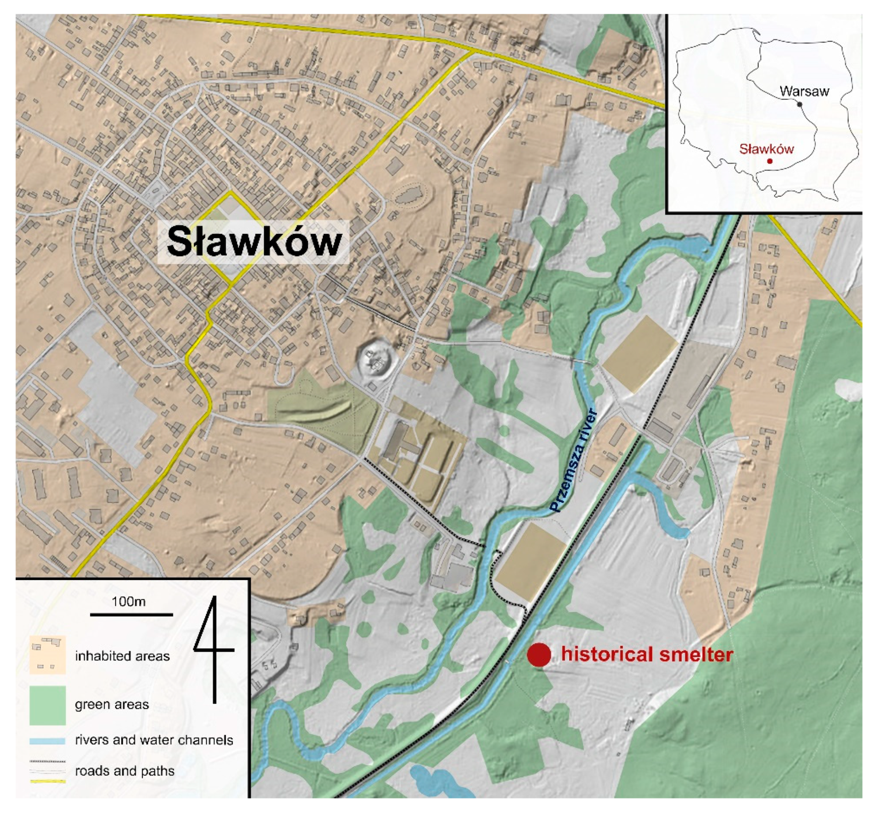
2. Location and Ore Exploitation

Sławków is one of the oldest centers related to lead metallurgy in Poland. It is located in southern Poland (Figure 1), between Dąbrowa Górnicza and Sosnowiec in the west and Olkusz in the east. The town was an important economic center in the Middle Ages. Apart from mining and metallurgy, Sławków was an important trade center, situated on the route connecting the east and west of Europe [36]. In the Middle Ages, the administration of industry in the Sławków region was carried out by the Archbishop of Cracow [9]. We can be certain that Ag-Pb ores were exploited and processed from the 15th to the 19th century, but it is assumed that a metallurgical industry existed in the Sławków region much earlier [9,37]. The ore mineralization in this area is associated with Mississippi Valley type deposits. These are low-temperature epigenetic deposits occurring in the Middle Triassic dolomites [38]. Primary ore mineralization consists mainly of galena (PbS), sphalerite and wurtzite (ZnS), pyrite and marcasite (FeS2) [38]. However, due to weathering processes, the ore minerals should also include smithsonite (ZnCO3), monheimite (FeZnCO3), hydrozincite (Zn[(OH)3CO3]2), cerussite (PbCO3), Fe-oxides, and hemimorphite (Zn4(Si2O7)(OH)2·H2O) [39]. Initially, exploitation was limited to shallow deposits. After the resources above the groundwater table were exhausted, attempts were made to deepen and drain the mines. However, due to the lack of appropriate technology, these activities were limited [9]. Lead smelting in Sławków was carried out in the smelter located on Quaternary sands and muds [9]. It was placed in the south-eastern part of the city, near the left bank of the Przemsza River (Figure 1). Historical information [40] describes the existence of two independent “Old” and “New” smelters in this area. Both functioned in the 17th century, and at least the old smelter also in the 16th century [40]. Currently, there are no traces of the smelters’ buildings in the area. Their location can only be identified by elevated terrain and slags appearing on the surface.

3. Materials and Methods

3.1. Sampling

Forty-two slag and eleven brick samples were collected from the surface and in excavations related to the bicycle path carried out in the historical landfill. Based on the macroscopic differentiation and the degree of weathering, three main types of slags were distinguished, from which representative fragments were subjected to preparation and geochemical and petrological analyses. Two brick samples were selected for preparations and SEM-EDS analyses to confirm their relationship to the smelting process.

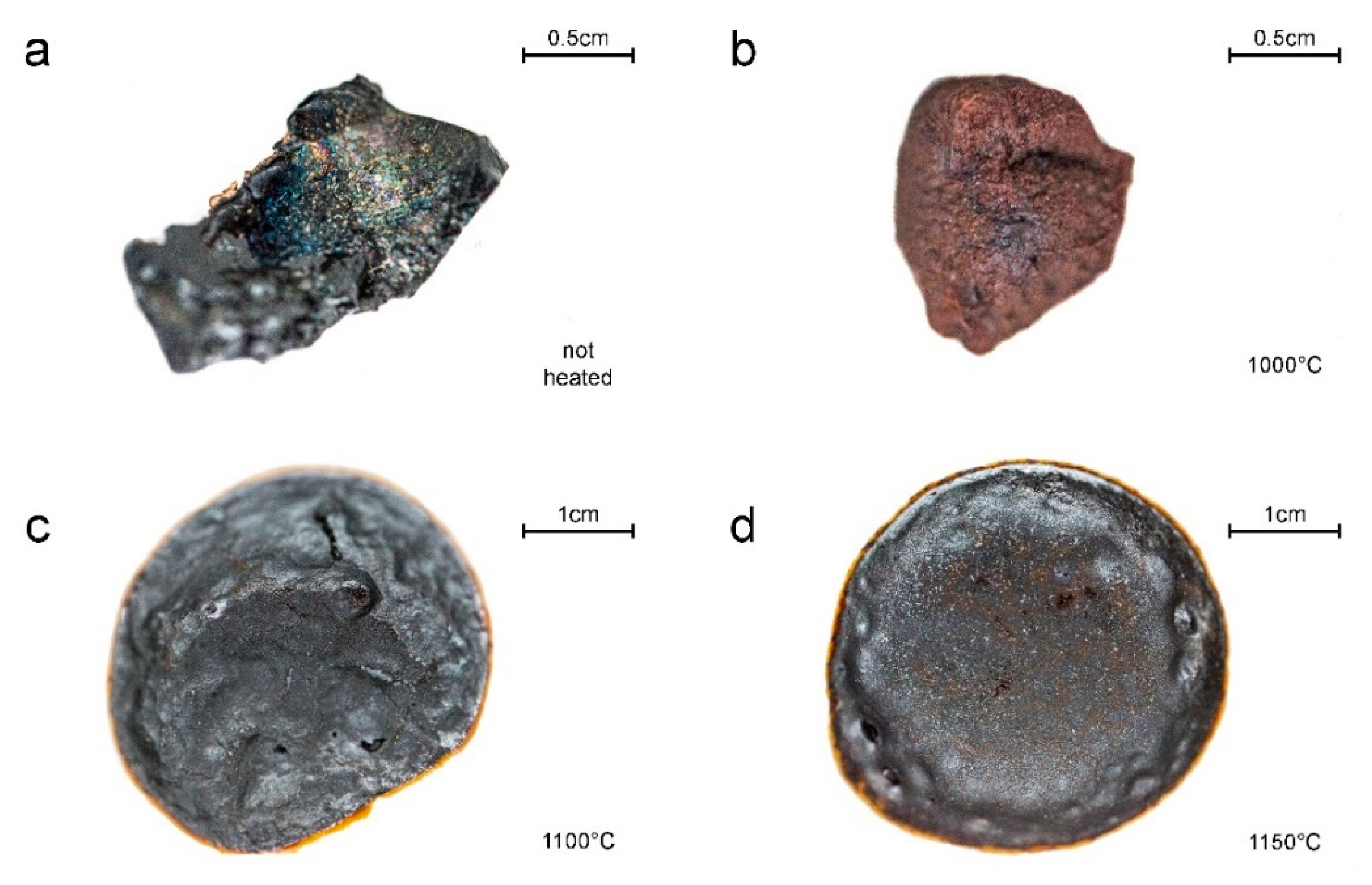
3.2. Furnace Experiments

Experiments were performed in PLF 160/5 chamber furnace (Protherm, Ankara, Turkey) with a PC 442/18 controller, SiC heaters, and a thermocouple S with a maximum working temperature of 1550 °C. Samples were melted in alumina pots. To determine the melting temperature of the slag samples we performed successive experiments with rising temperatures and fast cooling until a complete melting of the sample (ca. 1 cm3) had occurred.

3.3. Geochemical and Petrological Analyses

For quantitative and qualitative phase composition of samples, samples were examined using the Olympus BX-51 (Tokyo, Japan) polarizing microscope, scanning electron microscope (SEM; Thermo Fisher Scientific Phenom XL, Waltham, MA, USA), equipped with an energy-dispersive spectrometer (EDS) at the Faculty of Natural Sciences, University of Silesia and Electron probe micro-analyzer (EPMA) CAMECA SX 100 (Gennevilliers, France) at the Inter-Institutional Laboratory of Microanalysis of Minerals and Synthetic Materials, University of Warsaw. EPMA analyses were performed at 15 keV accelerating voltage, a 10–20.1 nA beam current, and a beam diameter of up to 5 µm. Standards included: Al—KAlSi3O8; As—GaAs; Ba—BaSO4; Ca—CaSiO3; Fe—Fe2O3; K—KAlSi3O8; Mg—MgCaSi2O6; Mn—MnCO3; Na—NaAlSi3O8; P—Ca5(PO4)3(F,Cl,OH); Pb—PbS, PbCrO4; S—BaSO4, CuFeS2, ZnS; Si—CaSiO3; Ti—TiO2; V—V; Zn—ZnS.
X-ray powder diffraction data were obtained using an X’PERT PRO—PW 3040/60 diffractometer (PANalytical Malvern, UK; CoKα1 source radiation, Fe-filter to reduce the Kβ radiation, and X’Celerator detector), at the Faculty of Natural Sciences, the University of Silesia in Katowice. Quantitative data processing was performed using the X’PERT High Score Plus software using the latest PDF4+ database and applying the Rietveld method. The Rietveld method applies the least-squares approach to match the theoretical profile line with a measured peak intensity of a powder sample, thus minimizing the residual function, and refining the crystal structure of the compound.
Considering insignificant differences of glassy slag in SEM and EPMA analyses for the bulk chemical compositions we used large (ca. 7.5 kg) and averaged sample of this slag type to better reflect their mean composition. It was supplemented by two samples of crystalline and weathered slags and analysed by a combination of X-ray fluorescence (XRF) spectrometry and inductively coupled plasma mass spectrometry (ICP-MS) for a broader spectrum of major, minor, and trace elements. Analyses were performed by the Bureau Veritas Minerals Laboratories. Sample preparation consisted of LiBO2 fusion for XRF and lithium tetraborate decomposition and aqua regia digestion for ICP-MS. Loss on ignition was determined before XRF at 1000 °C.

3.4. Software

The furnace design was developed using Autodesk AutoCAD 2021 (San Rafael, CA, USA) and Adobe Photoshop 2021 software (San Jose, CA, USA).

4. Results

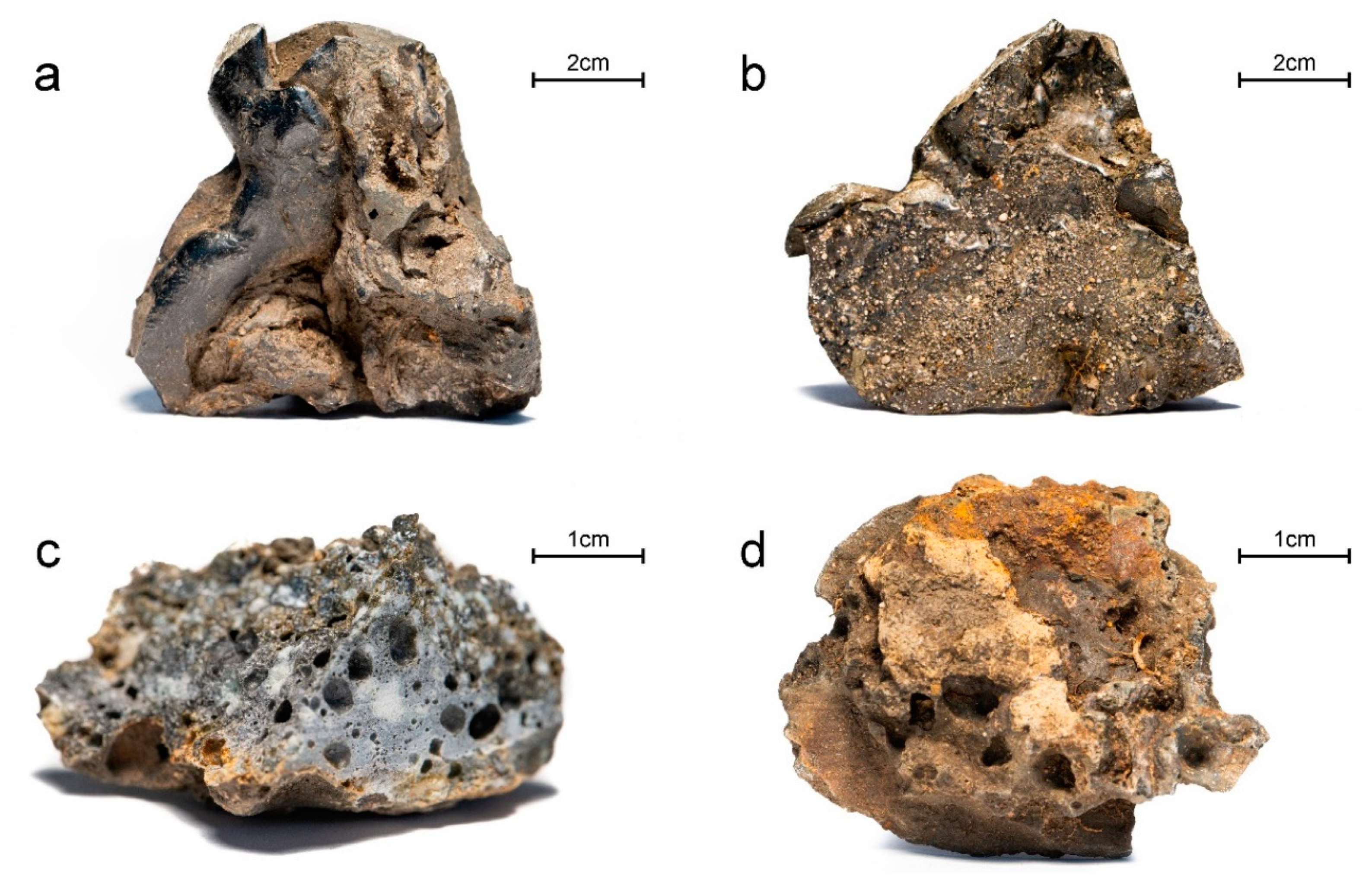
4.1. Slag Types at Sławków Landfill

Based on macroscopic observations it is possible to distinguish three main types of slags occurring at the landfill (Figure 2): (i) glassy slag with commonly incorporated grains of sand; (ii) crystalline slags; (iii) slags showing signs of weathering processes. Glassy slag is most common (33 samples from 42 gathered). It is black and gray with a yellow coating and is characterized by flow structures (Figure 2a) and incorporated grains of sand (Figure 2b). Crystalline slag is less common (five among 42 samples). This type of slag is gray, porous and in the section, partly melted grains are visible (Figure 2c). Weathered slags are uncommon at the landfill (four among 42 samples). They are porous, yellow to brow, with coatings of secondary mineralization (Figure 2d).

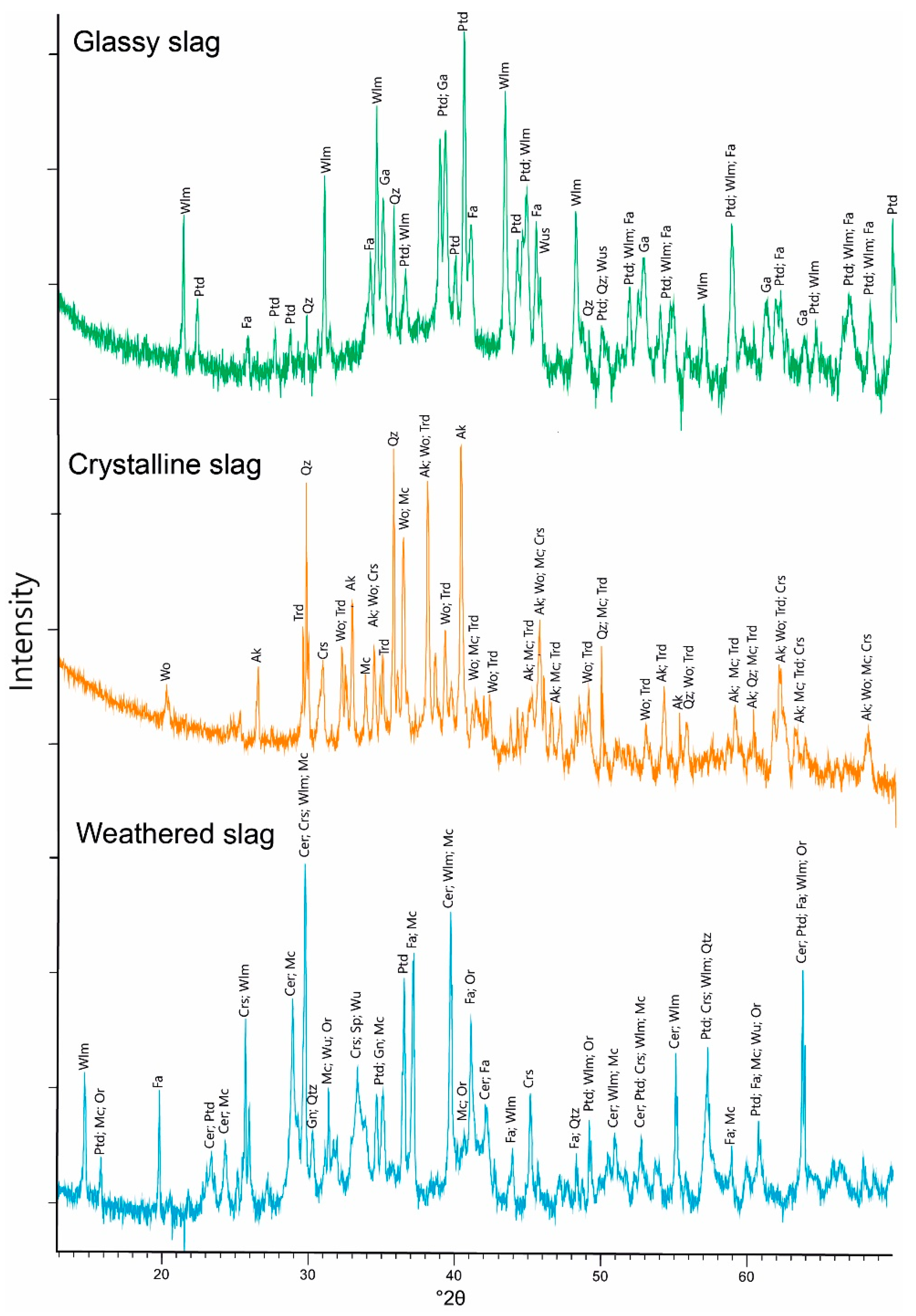
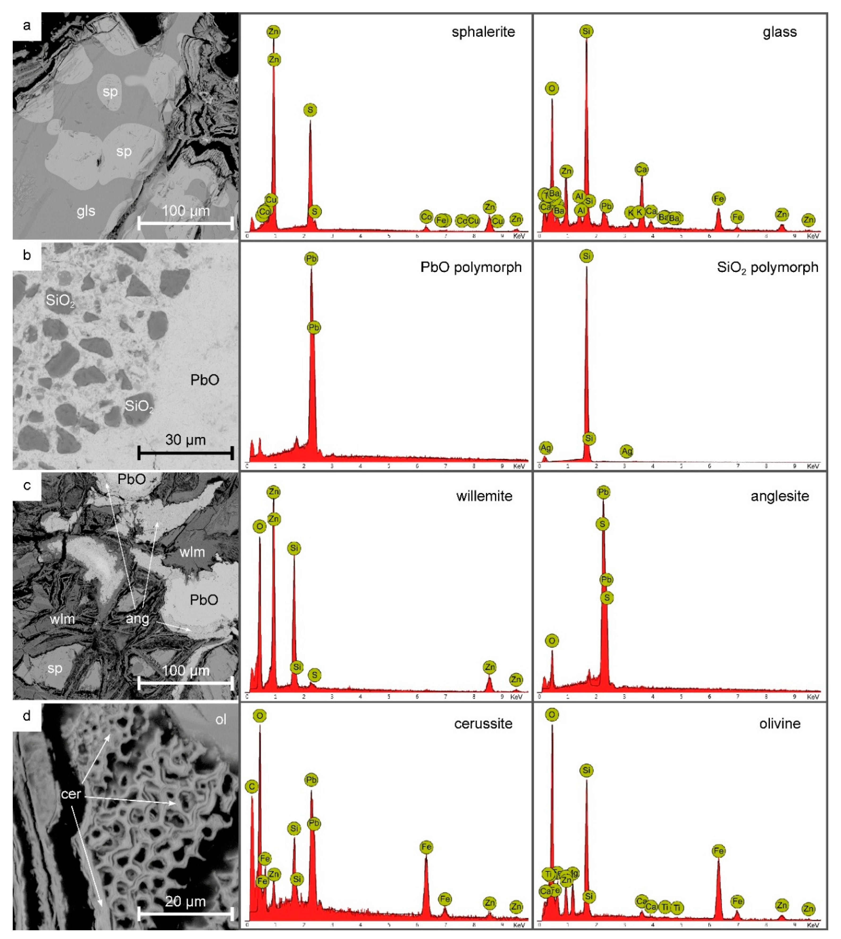
4.2. Phase Composition and Chemistry of Phases
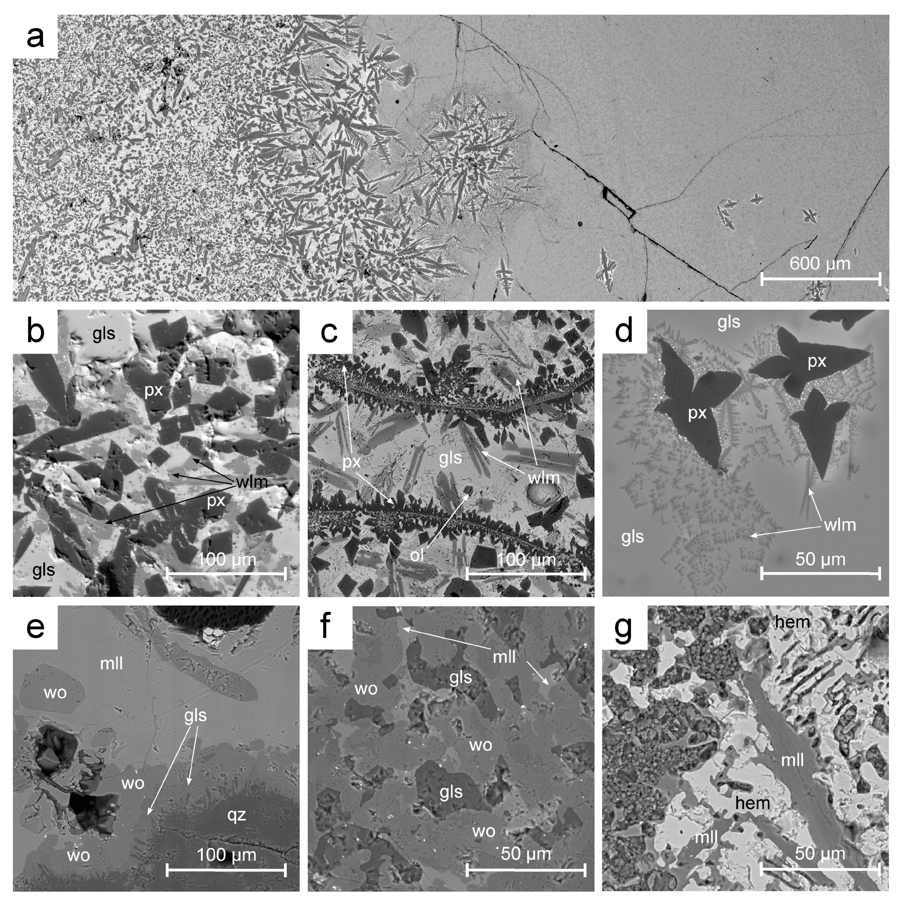
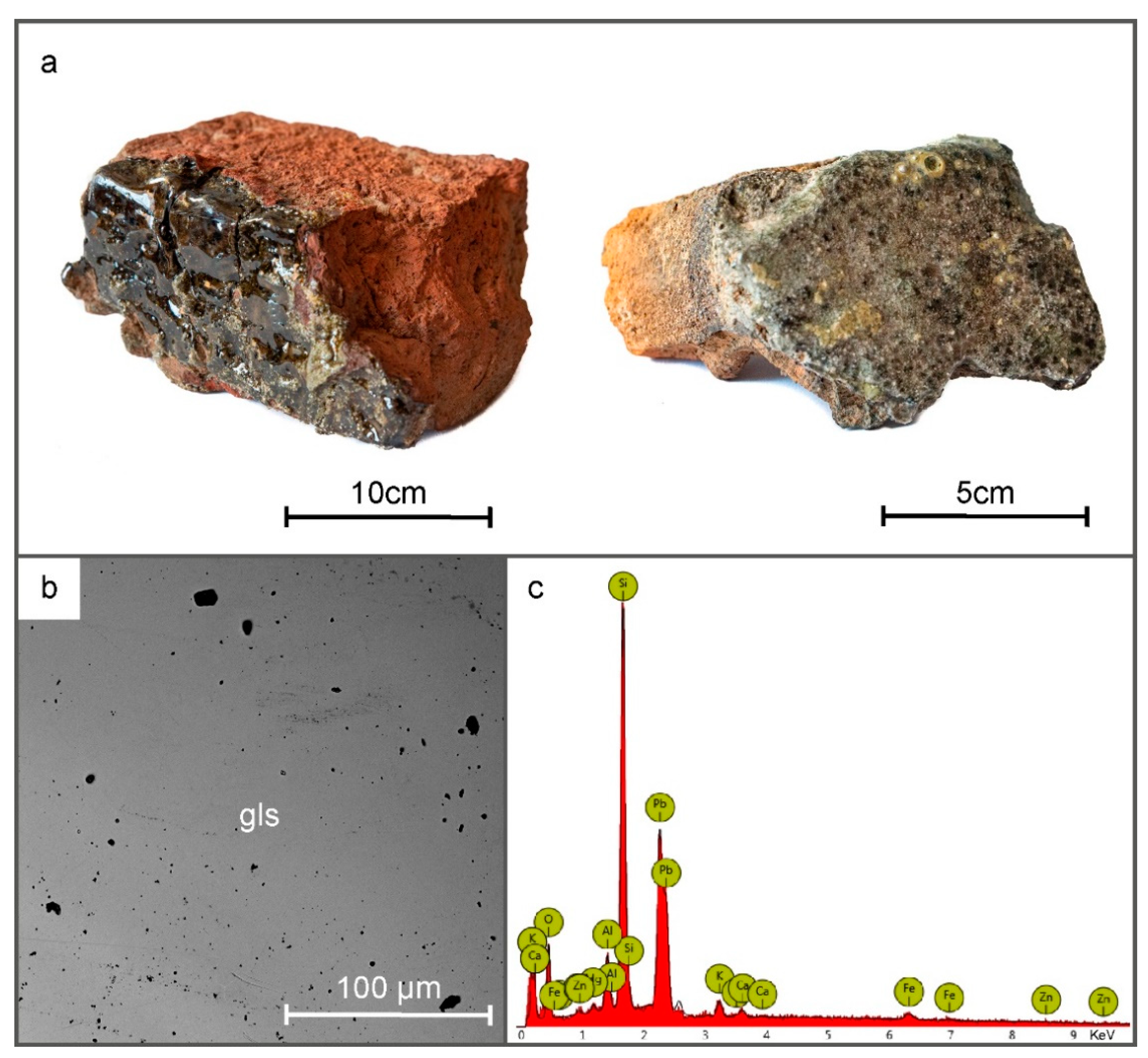
4.2.1. Glassy Slag

According to the XRD data (Figure 3) the glassy slag is dominated (42 vol.%) by petedunnite (Ca(Zn,Mn2+,Mg,Fe2+)Si2O6), accompanied by the willemite (31 vol.%; Zn2SiO4), fayalite (16 vol.%; Fe2SiO4), quartz (5 vol.%; SiO2), galena (3 vol.%; PbS) and wüstite (3 vol.%; FeO). The diffractogram shows the hump characteristic for samples containing amorphous phases (Figure 3). Within the glassy slag, we observed areas that are composed of an amorphous phase with only singular crystallites (Figure 4a,d) and more crystalline zones (Figure 4b,c). Considering the phase dependencies in glassy slag we can determine that crystallization was started by the star-shaped pyroxene up to 100 μm, followed by dendritic crystals of willemite (Figure 4a,d). With an increasing level of crystallinity of zone, pyroxene gains subhedral morphology with crystals up to 200 μm (Figure 4a–c), while willemite forms laths up to 200 μm in length (Figure 4a–c). Occasionally they are accompanied by olivine up to 20 μm across (Figure 4c).
Based on the EPMA data we can distinguish two generations of pyroxenes within glassy slag. The proportion of Ca:Mg:Fe makes both generations augite, although the first is Mg-enriched (Wo32En57Fs11), while the second Ca and Fe-enriched (Wo44En19Fs37) (Table 1). In opposition to Mg-rich augite, Fe-augite concentrates also Zn (up to 7.34 wt.% of ZnO; Table 1) moving its composition closer to the petedunnite. Willemite in glassy slag is characterized by the significant addition of Fe (up to 18.29 wt.% of FeO) and lower concentrations of Mg, Mn, and P (Table 1). Olivine has close to ideal, forsterite dominated (Fo84) composition (Table 1). Lead oxide phases are enriched in minor amounts of Zn (up to 0.40 wt.% of ZnO) and Fe (0.37 wt.% of FeO) (Table 1). Amorphous phase in glassy slag has a diverse composition consisting mainly of Pb (8.88–39.51 wt.% of PbO), Si (30.89–38.55 wt.% of SiO2), Fe (11.46–21.27 wt.% of Fe2O3), Zn (4.92–12.61 wt.% of ZnO) and Ca (3.19–11.15 wt.% of CaO) (Table 1).
Besides glass concentrates numerous (Al, Mg, K, P, Na, S, Mn, and Ti) of other elements in lower amounts (Table 1). Differences in the glass composition are due to the advancement of the crystallization process. Primitive glass in areas with none or rare crystallites is enriched in Si, Fe, Zn, Mg, and Ca (Table 1). Crystallization of phases containing these elements (pyroxene, olivine, willemite) leads to the enrichment of residual glass in Pb and K which are incompatible with crystallizing phases.

4.2.2. Crystalline Slag

According to the XRD data (Figure 3), the crystalline slag consists of åkermanite (43 vol.%; Ca2Mg(Si2O7)), SiO2 polymorphs (27 vol.% in total; 14 vol.% of quartz; 11 vol.% of tridymite; 2 vol.% of cristobalite), wollastonite (20 vol.%; CaSiO3), and microcline (10 vol.%; KAlSi3O8). The petrographic image of crystalline slag is largely determined by the occurrence of quartz grains up to a few hundred of μm across. Their surface is locally covered by a thin (few μm) layer of glass (Figure 4e) resulting from quartz melting and recrystallization and exchange of cations with melt. Further from the surface of quartz grains wollastonite layer (up to 30 μm thick) crystallizes followed by anhedral melilite building the slag matrix (Figure 4e). Spaces in slag between quartz grains are filled with overgrown anhedral crystals (up to 60 μm across) of wollastonite and melilite accompanied by feldspars, glass, and occasionally by rankinite (Ca3Si2O7, Figure 4f). Rarely segregations rich in anhedral spinel and hematite up to 100 μm occur in this slag type (Figure 4g).
Wollastonite occurs as crystals with an almost pure chemical composition (Table 2) or with numerous substitutions among which Fe (11.17 wt.% of FeO); Zn (2.31 wt.% of ZnO); Mg (1.57 wt.% of MgO) and K (1.02 wt.% of K2O) (Table 2) are most significant. Analyzed melilites belong to the complex solid solution of åkermanite (Ca2Mg(Si2O7))—gehlenite (Ca2Al(AlSiO7))—hardystonite (Ca2Zn(Si2O7))—ferri-gehlenite (Ca2Fe3+(AlSiO7)) (Table 2). As such, they concentrate wide spectrum of elements: Al (1.36–27.43 wt.% of Al2O3), Fe (6.25–9.28 wt.% of Fe2O3), Zn (1.15–11.92 wt.% of ZnO), and Mg (0.63–2.42 wt.% of MgO) (Table 2). Rankinite has a composition close to ideal: Ca2.96Fe0.03Si2O7 (Table 2). Plagioclase is represented by the Ca-rich endmember (An93) enriched in Fe (1.04 wt.% of FeO), Zn (0.45 wt.% of ZnO), and Pb (0.22 wt.% of PbO) (Table 2). K-feldspar contains only minor amounts of Fe (0.62 wt.% of FeO) (Table 2). Due to numerous elements in its structure spinel can be classified as magnetite (Fe2+Fe3+2O4)—gahnite (ZnAl2O4)—franklinite (Zn2+Fe3+2O4)—hercynite (Fe2+Al2O4)—chromite (Fe2+Cr3+2O4)—coulsonite (Fe2+V3+2O4) solid solution (Table 2). Hematite (ideally Fe2O3) additionally concentrates Ti (0.52–7.93 wt.% of TiO2), Al (3.28–11.57 wt.% of Al2O3), V (0.00–1.92 wt.% of V2O3), Mn (0.65–0.77 wt.% of MnO), Zn (0.99–6.60 wt.% of ZnO), Mg (0.00–2.50 wt.% of MgO), and Ca (0.62–1.12 wt.% of CaO) (Table 2). Compared with amorphous phases from glassy slag, here they are enriched in Si (mean 73.17 vs. 34.72 wt.% of SiO2), Al (mean 10.10 vs. 2.49 wt.% of Al2O3), and K (mean 4.06 vs. 1.87 wt.% of K2O)(Table 2). At the same time they are impoverished in Fe (mean 6.05 vs. 16.37 wt.% of Fe2O3), Zn (mean 2.66 vs. 8.76 wt.% of ZnO), Pb (mean 1.20 vs. 24.20 wt.% of PbO), and Ca (mean 1.51 vs. 7.17 wt.% of CaO) (Table 2).

4.2.3. Weathered Slags

According to XRD data weathered slags are composed of a mixture of ore minerals, primary slag-building, and secondary phases. Ore minerals are represented by sphalerite and wurtzite (2.5 vol.%), and galena (1 vol.%) (Figure 3). The following primary phases were distinguished: fayalite (25.5 vol.%), K-feldspars (20 vol.%), and petedunnite (15 vol.%), and cristobalite (2 vol.%) (Figure 3). Secondary phases are represented by the cerussite (PbCO3; 6.5 vol.%). Willemite (27.5 vol.%) (Figure 3) may be the result of both the smelting process and weathering of the slags.
SEM-EDS confirmed the presence of all mineral groups distinguished in XRD (Figure 5). Ore minerals are represented by the sphalerite/wurtzite, which forms partly melted crystals up to 100 μm across, surrounded by the glass with a composition similar to the primary one from glassy slag as it is rich in Si, Ca, Zn, Pb, Fe, K, Al, and Ba (Figure 5a).
Quartz (or its polymorphs) form small grain (up to 20 μm) dispersed in the PbO phase (Figure 5b). As a result of the weathering of PbO, anglesite (PbSO4) forms as layers around the PbO core (Figure 5c). It co-occurs with secondary willemite forming irregular lath/needle aggregates, which in opposition to the primary willemite, lacks in Fe (Figure 5c). Olivine forms anhedral crystals to a few dozens of μm (Figure 5d). Cerussite is common among secondary minerals, and it forms highly irregular layered aggregates up to 50 μm (Figure 5d; due to the small width of singular layers cerussite EDS contains elements from neighbor phases).

4.3. Chemical Composition of Slags

Glassy slag is mainly composed of the Si (34.58 wt.% of SiO2), Fe (21.65 wt.% of Fe2O3), Ca (11.19 wt.% of CaO), Mg (3.39 wt.% of MgO), Al (1.81 wt.% of Al2O3) and K (1.19 wt.% of K2O) (Table 3). It also contains extremely high amounts of Pb (above the detection limit of the method which was 10 wt.%) and Zn (13.25 wt.%) (Table 3). Among trace elements five concentrates above 100 ppm: As, Ba, Cu, Sr, and Sb (Table 3). The chemistry of the glassy slag almost perfectly fits the composition of the primary glass occurring within this slag type (Table 1). Crystalline in comparison with glassy slag is enriched in Si (46.50 wt.% of SiO2), Ca (30.39 wt.% of CaO) and Al (3.50 wt.% of Al2O3) (Table 3), but is impoverished in Fe (9.81 wt.% of Fe2O3), Mg (0.99 wt.% of MgO), Pb (1.07 wt.%), Zn (2.83 wt.%) (Table 3). Weathered slag has the lowest content of Si (26.18 wt.% of SiO2), Ca (4.48 wt.% of CaO), Al (1.17 wt.% of Al2O3), K (0.28 wt.% of K2O) (Table 3), but highest of Fe (22.83 wt.% of Fe2O3), Mg, (4.31 wt.% of MgO), Zn (21.50 wt.%) (Table 3) and lead, which similarly to glassy slag reached detection limit of the method (10 wt.%) (Table 3).

4.4. Melting Point of Slags

As a consequence of heating, slags have undergone the following changes: (i) after heating in temperatures of up to 1000 °C, the colour of the slag changed to rusty-red, and the morphology of the sample became more oval (Figure 6b); (ii) heating up to 1100 °C caused melting of the sample in the entire volume, but the result is not fully unified; (Figure 6c); (iii) after heating in the temperature of up to 1150 °C, the slag is completely melted and unified (Figure 6d).

5. Discussion

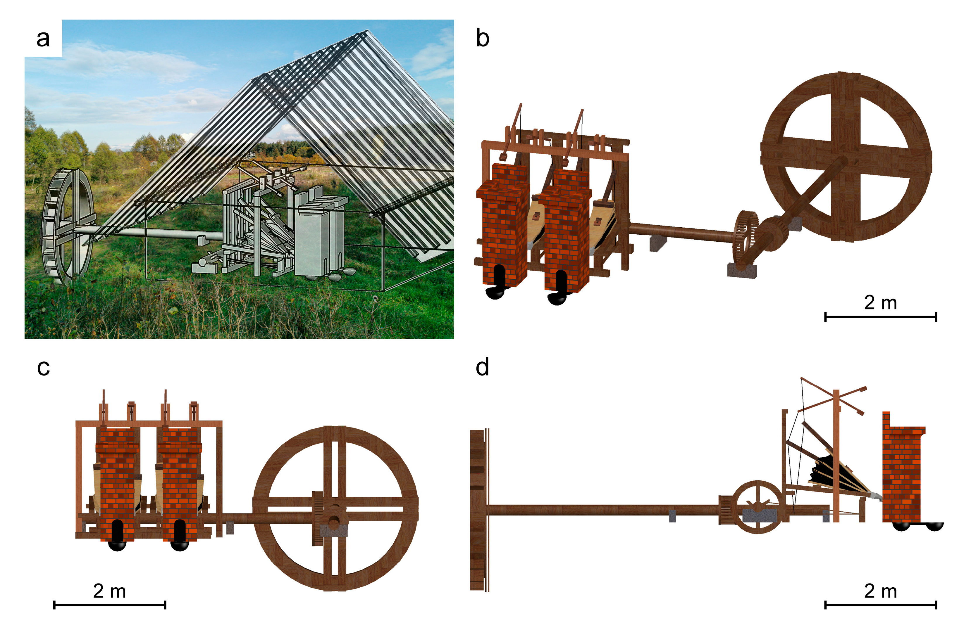
5.1. Furnace Construction

Based on historical sources [22] and archaeological research [43] it is known that lead smelting in Sławków was divided into several stages. The first step in preparing the ore for further processing was enrichment. For this purpose, after the rocks were brought to the surface, they were crushed. Crushed ore was washed. Rinsing led to the separation of heavy minerals (containing lead) in specially prepared troughs [22,43]. During the archaeological research in the vicinity of Olkusz, the presence of this type of installation was found [43]. Lead ore might have been roasted by setting fire to a pile of wood with crushed ore [22]. This activity allowed the workers to get rid of sulfur and other unnecessary ingredients. As a result of roasting, sulfide minerals were oxidized, which in the later stages facilitated the smelting process. Historical data from Sławków [40] describes the existence of roasters in a neighbor of the smelter, thus we can assume that this process was used in Sławków. Smelting was carried out in a brick blast furnace. This was confirmed by the presence of bricks irregularly covered by the glass (Figure 7a) with a composition of glassy slag (Figure 7b,c). From the descriptions contained in the De Re Metallica [22], and other data [40] we attempted reconstruction of the smelter construction (Figure 8). Most often lead smelting installations consisted of six furnaces arranged in a sequence [22] while in Sławków there were only two [40] (Figure 8). In the room behind the blast furnaces, there were four bellows (powered by water from the Przemsza River) [40]. The bellows’ nozzles were introduced into the furnace through an opening in the rear wall. In turn, the raw materials for production (e.g., ore, charcoal) were stored in rooms located in front of the furnaces. Before melting, the furnace had to be properly prepared. For this purpose, the internal walls and settling tanks were covered with a layer of a mixture of charcoal and clay. After preparation, the furnace was filled with charcoal. Then the ore was added [22]. During heating, lead and slag flowed to the bottom of the furnace. At the bottom, there was a settling tank (internal) in which the liquid lead and slag accumulated. Due to the difference in density, liquid lead accumulated at the bottom of the settler, followed by a layer of slag. After filling the internal settling tank, slag flowed through the drain hole to the settling tank in front of the furnace. The outflowing slag was removed by workers and tossed on the ground which contained sand (Figure 2b) [9]. Lead smelting was often carried out for several days. This was possible because the tapping holes were not closed, and the molten slag and lead could continuously flow out of the furnace [22].

5.2. Temperature Estimates

We decided to use an experimental approach to estimate the temperature during smelting in Sławków. Bearing in mind the fact that the slag is composed of elements almost entirely in the oxidized form (Table 1), this method should ensure precise estimations of temperature conditions during the historical smelting process, regardless of oxidation that might occur during experiments. Due to the diversified chemical composition, which includes eight main elements (Si, Fe, Zn, Pb, Ca, Al, K; Table 3), the application of popularly used [10,12,21,44] phase diagrams would be burdened with a significant error due to the depreciation of the liquidus by the elements not included. The phase composition (Figure 3) and the non-equilibrium crystallization of the material make it impossible to use geothermometers [21,44]. The conducted experiments indicate that the temperature during the metallurgical process was at least 1150 °C (Figure 6). At this temperature, the slag sample was entirely melted and unified, with the solidus for this material in the range of 900–1000 °C (Figure 6). On the base of experiments, in the 12th century, Ag-Pb furnace from Łosień (Polska) temperatures could be as high as 1450–1550 °C [8]. In 13th–14th century Cu-Pb-Ag slags from Massa Marittima (Italy), the estimated solidification temperatures were 1150–1300 °C [30]. In the case of material from Bohutín (14th century Ag-Pb slags, Czech Republic), the estimated temperature of melting based on phase diagrams was around 800–1200 °C [10]. The temperature during smelting process of Ag in the 14th–15th century in Kutná Hora was estimated at 1150–1300 °C [32]. In high-medieval Ag-Pb slags from Wiesloch (Germany), based on experiments, liquidus was at ca. 1100 °C [12]. The obtained temperature for the metallurgical process in Sławków coincides with the mentioned locations. Moreover, the reduction of furnace temperature over the centuries can be observed. This phenomenon is probably due to advancements in the metallurgical process and deepening knowledge about metal smelting. The later (19th century and later) smelting of MVT ores in Poland was carried out at higher temperatures up to 1350 °C [21], which, however, resulted from a different technological process and, above all, the recovery of Zn and not Pb.

5.3. Ores and Additions

The smelter in Sławków used the MVT deposits occurring in this area. As mentioned ore mineralization consists mainly of sulphides (galena, sphalerite, wurtzite, pyrite, and marcasite) and carbonates/silicates (smithsonite, monheimite, hydrozincite, cerussite, hemimorphite) as calamine, hosted in Middle Triassic dolomites [38,39]. Considering that the shallow deposits of calamine were probably exhausted by the 16th century, the activity of the smelter had to be based on sulphides. Confirmation of this fact is the existence of roasting furnaces [40] at the smelter for the oxidation of sulphide ores. The low content of sulphur (Table 3) in all slag types proves the high efficiency of the process. In crystalline and weathered slag, we found the presence of minor amounts of galena, sphalerite, and wurtzite (Figure 3), which additionally confirms the use of sulphide ores. Considering the phase (Figure 3) and chemical composition (Table 3), and the fact that used ores do not contain large amounts of silicates [38,39], the main addition in the process had to be SiO2 concentrating phases. Its addition is responsible for separating and binding impurities formed during smelting from the obtained lead. Considering the location of the smelter near the river (Figure 1), river sand was an easily accessible source of this element, which was also indicated by the presence of fused quartz grains in the crystalline slag (Figure 4e). The use of sand in the historical lead recovery process has already been described in Łosień (Poland), Prague, and Kutná Hora (Czech Republic) [8,24,32]. The high iron content (up to 22.83 wt.% Fe2O3; Table 3) resulted from its common occurrence in the ore in the form of sulphides, mainly pyrite and marcasite [38,39]. Due to their overgrowth with galena in the deposits, it could not be effectively removed. This fact did not have an impact on the lead yield because Fe was bound in the oxide and silicate phases (Table 1 and Table 2) that prevented the contamination of the lead obtained. Crystalline slag has a significantly different chemical composition from the glassy one (Table 3). It contains increased levels of SiO2 (46.50 vs. 34.58 wt.%), CaO (30.39 vs. 11.19 wt.%), and Al2O3 (3.50 vs. 1.81 wt.%), and it is depleted in the elements building ore mineralization, i.e., Pb, Zn, and Fe (Table 3). The phase composition is also dominated by minerals characteristic of high-calcium rocks, e.g., wollastonite, rankinite, melilite (Figure 3, Table 3). The existence of this type of slag may be associated with errors during smelting: not thorough cleaning of the ore from dolomite (increasing CaO amount, and decreasing the concentration of ore elements (Table 1) and too high sand addition (increasing the SiO2 content; Table 3). Slags with similar phase composition were described in Na Slupi site, Prague (Czech Republic) [24], but they were considered a product of Ag production using the cupellation process. Existing historic data [40] does not mention Ag production in Sławków smelters thus until new information becomes available, we insist on the thesis of poor charge preparation. Moreover, the rare character of crystalline slag indicates the periodic occurrence of similar episodes during the existence of the smelter.

5.4. Atmosphere

The metallurgical process must have taken place under reducing conditions as they were necessary to obtain the metallic lead. However, the presence of zinc in the silicate and oxide phases indicates a significant variation in the oxygen fugacity within the metallurgical furnace. In reducing conditions and at temperatures above 907 °C [44], zinc vaporizes, and in this form, it migrates to the upper part of the furnace by convection. Under stabile reducing conditions, it would be completely removed from it. The high content of zinc in the slag (up to 13 wt.% In the glass slag; Table 3) indicates its secondary oxidation to ZnO with a boiling point of 2360 °C [44], which is significantly above the values obtainable in a similar process. Oxidation of Zn could have taken place in the upper parts of the furnace where the influence of C and CO is limited, or near the bellows supplying oxygen for the combustion of charcoal. In the oxidized form, zinc could react with the melt and enter the structure of almost all phases forming the studied slags (Table 1 and Table 2). Increased Zn contents are typical for slags after Ag and Pb production [17,31,32]. Even higher Zn contents (up to 23 wt.% ZnO) were described in Wiesloch (Germany) [12], where, despite the different structure of the furnace, its concentration was explained based on the same thermodynamic relations. The coexistence of wüstite (Figure 3), hematite, and spinel (Table 2) within the analyzed slags additionally emphasizes large fluctuations in oxygen fugacity (from −12 log f O2 for wüstite-magnetite oxygen buffer to −4.5 log f O2 for magnetite-hematite oxygen buffer at a temperature of 1150 °C, the pressure of 1 bar [45]). The presence of these phases was found and similarly interpreted also in slags from other locations, e.g., Bohutín (Czech Republic) [10], Wiesloch (Germany) [12] and Massa Marittima (Italy) [31].

5.5. Viscosity

The melts viscosities have been widely studied in slag researches. It is due to the impact of melt viscosity on the segregation of components, the speed of crystallization, or the recovery of metals in the metallurgical process. The commonly used [10,46,47] method of calculating the melt viscosity index (v.i.) in archaeological research was developed by Bachmann [48]. The method base on the proportion of polymerizing to depolymerizing components in the silicate melt (values in wt.%):
v.i. = (CaO + MgO + MnO + FeO)/(SiO2 + Al2O3)
Lower values of v.i. indicate a higher melt viscosity. In the case of the studied slags, their viscosity index ranges from 0.83 (crystalline slag) to 1.00 (glassy slag). These values are within the range proposed by Bachmann [48], according to which the values of v.i. are within 0.5–1. The glassy slag is characterized by a lower viscosity, which should have resulted in easier separation of the lead from it. This confirms that the smelting process that resulted in the formation of crystalline slag was less efficient. Values of v.i. for other locations often exceed the limits proposed by Bachmann [48]: for Mass Marittima (Italy), it ranges from 0.79 to 3.74 [31], and for Bohutín (Czech Republic) from 0.08 to 1.58 [10]. Due to the high content of elements not included in the original Bachmann equation, a corrected formula has been proposed [10] that takes into account the high amount of lead and zinc:
v.i. = (CaO + MgO + MnO + FeO + PbO + ZnO)/(SiO2 + Al2O3)
In this case, v.i. values of the slags from Sławków are elevated, especially in the case of glassy slag where it reaches 1.75. This indicates the importance of considering the influence of other elements in lowering the melt viscosity. A similar change was observed by Ettler et al. [10]. In the case of the Bohutín slags, where slags v.i. increased to 0.57–2.25.
Another method of calculating the viscosity was proposed by Giordano et al. [49]. This model is based on the chemical composition in mol% and calculates the viscosity values (Pa s) at the indicated temperatures according to the formula:
log10η = b1 + (b2 · b3)/(b3 + SM) + b4
where b1–b4 are temperature-dependent parameters derived from the model, and SM is structure modifier calculated as Σ mol% (Na2O + K2O + CaO + MgO + MnO + FeOtot/2). In our study, we followed the modification proposed by Ettler et al. [10] including PbO and ZnO in the calculations. Details of the model can be found in the original publication by Giordano et al. [49]. For a temperature of 1150 °C and composition of Sławków slags, their viscosity is log η = 1.34 Pa s for glassy slag and 1.48 Pa s for crystalline slag. At the temperature of 630 °C (model [49] has been designed for the temperature range 630–2000 °C) the log η value increases to 11.71 Pa s for glassy slag and 11.88 Pa s for crystalline slag, showing rising viscosity as the melt cools down. The difference between these two types of material is consistent with the previous calculation methods. The viscosity of the slags in Bohutín was significantly higher (average log η = 2.20 Pa s for 1200 °C), which results from the much higher concentration of SiO2 found in them [10].

6. Conclusions

The conducted research has allowed for the reconstruction of the lead smelting process in Sławków in the 16th–17th centuries. It confirms that the furnaces existing in the smelter had a brick structure, as evidenced by the finding of their glass-covered fragments with a glass composition corresponding to the slag from the location. In conjunction with literature studies, it was determined that the process based on the sulphide ores, which were roasted before the actual smelting. The furnace charge consisted of roasted ore, charcoal, and quartz sand. The addition of SiO2 served to bind impurities in the form of glassy slag. During the smelting process, reducing conditions enabling to obtain metallic Pb prevailed, however, in the studied slags there were found phases (co-occurrence of wüstite, magnetite, and hematite) and elements indicating differentiated oxygen fugacity in the furnace. It probably resulted from the greater availability of oxygen in the highest part of the furnace and the vicinity of its supply with bellows. The characteristics of the slag show that the employees of the smelter were knowledgeable about the conditions during smelting. Despite the addition of SiO2, the low melt viscosity was maintained (logη = 1.34 for 1150 °C), which facilitated the separation of metallic lead by density. Moreover, the melting point of the system was as low as 1150 °C. The obtained results in comparison with the data presented for earlier periods (early to late Middle Ages) illustrate the growing knowledge about lead smelting techniques, in particular in terms of the importance of additives on the course of the liquidus of the system and the effectiveness of metal separation from the melt.

Supplementary Materials

The following are available online at https://0-www-mdpi-com.brum.beds.ac.uk/2075-163X/10/11/1039/s1, Figure S1: three-dimensional design of the furnace in Sławków.

Author Contributions

Conceptualization, R.W. and M.S.; methodology, R.W., M.S. and K.K.; software, R.W., M.S. and K.K.; validation, R.W., M.S. and K.K.; formal analysis, R.W., M.S. and K.K.; investigation, R.W., M.S. and K.K.; resources, R.W., M.S. and K.K.; data curation, R.W., M.S. and K.K.; writing—original draft preparation, R.W., M.S. and K.K.; writing—review and editing, R.W., M.S. and K.K.; visualization, R.W., M.S. and K.K; supervision, R.W.; project administration, R.W.; funding acquisition, R.W. and K.K. All authors have read and agreed to the published version of the manuscript.

Funding

This study was supported by the National Science Center (NCN) grant no. 2016/21/N/ST10/00838 (awarded to RW), and National Science Center (NCN) grant no. 2019/35/O/ST10/00313 (awarded to KK).

Acknowledgments

We would like to express our deepest gratitude to the Society of Sławków Lovers (Towarzystwo Miłośników Sławkowa) for their help and support during the research.

Conflicts of Interest

The authors declare no conflict of interest.

References

  1. Waldron, H.A. Lead poisoning in the ancient world. Med Hist. 1973, 17, 391–399. [Google Scholar] [CrossRef] [PubMed] [Green Version]
  2. Rozmus, D. Wczesnośredniowieczne Zagłębie Hutnictwa Srebra i Ołowiu na Obszarach Obecnego Pogranicza Śląska i Małopolski (Druga Połowa XI–XII/XIII Wiek); Księgarnia Akademicka: Kraków, Poland, 2014. [Google Scholar]
  3. Yahalom-Mack, N.; Langgut, D.; Dvir, O.; Tirosh, O.; Eliyahu-Behar, A.; Erel, Y.; Langford, B.; Frumkin, A.; Ullman, M.; Davidovich, U. The earliest lead object in the levant. PLoS ONE 2015, 10, e0142948. [Google Scholar] [CrossRef] [PubMed] [Green Version]
  4. Hansen, S.; Montero-Ruiz, I.; Rovira, S.; Steiniger, D.; Toderaş, M. The earliest lead ore processing in Europe. 5th millennium BC finds from Pietrele on the Lower Danube. PLoS ONE 2019, 14, e0214218. [Google Scholar] [CrossRef] [PubMed]
  5. Krzywy, I.; Krzywy, E.; Pastuszak-Gabinowska, M.; Brodkiewicz, A. Ołów-Czy jest się czego obawiać. Rocz. Pomor. Akad. Med. W Szczec. 2010, 56, 118–128. [Google Scholar]
  6. Retief, F.P.; Cilliers, L. Lead poisoning in ancient Rome. Acta Theol. 2006, 26, 147–164. [Google Scholar] [CrossRef] [Green Version]
  7. Jerome, O.N. Lead and Lead Poisoning in Antiquity; Wiley: Amsterdam, The Netherlands, 1983. [Google Scholar]
  8. Cabała, J.; Warchulski, R.; Rozmus, D.; Środek, D.; Szełęg, E. Pb-rich slags, minerals, and pollution resulted from a medieval Ag-Pb smelting and mining operation in the Silesian-Cracovian region (southern Poland). Minerals 2020, 10, 28. [Google Scholar] [CrossRef] [Green Version]
  9. Mendecki, M.J.; Warchulski, R.; Szczuka, M.; Środek, D.; Pierwoła, J. Geophysical and petrological studies of the former lead smelting waste dump in Sławków, Poland. J. Appl. Geophys. 2020, 179, 104080. [Google Scholar] [CrossRef]
  10. Ettler, V.; Červinka, R.; Johan, Z. Mineralogy of medieval slags from lead and silver smelting (Bohutín, Příbram district, Czech Republic): Towards estimation of historical smelting conditions. Archaeometry 2009, 51, 987–1007. [Google Scholar] [CrossRef]
  11. Anguilano, L.; Timberlake, S.; Rehren, T. An early medieval lead-smelting bole from Banc Tynddol, Cwmystwyth, Ceredigion. Hist. Metall. 2010, 19, 85–103. [Google Scholar]
  12. Ströbele, F.; Wenzel, T.; Kronz, A.; Hildebrandt, L.H.; Markl, G. Mineralogical and geochemical characterization of high-medieval lead-silver smelting slags from Wiesloch near Heidelberg (Germany)—An approach to process reconstruction. Archaeol. Anthropol. Sci. 2010, 2, 191–215. [Google Scholar] [CrossRef] [Green Version]
  13. Kupczak, K.; Warchulski, R.; Dulski, M.; Środek, D. Chemical and Phase Reactions on the Contact between Refractory Materials and Slags, a Case from the 19th Century Zn-Pb Smelter in Ruda Śląska, Poland. Minerals 2020, 10, 1006. [Google Scholar] [CrossRef]
  14. Ploquin, A.; Allée, P.; Bailly-Maître, M.-C.; Baron, S.; de Beaulieu, J.-L.; Carignan, J.; Laurent, S.; de Veslud, C.L.C.; Lavoie, M.; Pulido, M. Medieval lead smelting on the Mont Lozère, southern France. In Proceedings of the Archaeometallurgy in Europe: International Conference, Milan, Italy, 24–26 September 2003; pp. 635–644. [Google Scholar]
  15. Warchulski, R.; Mendecki, M.; Gawęda, A.; Sołtysiak, M.; Gadowski, M. Rainwater-induced migration of potentially toxic elements from a Zn-Pb slag dump in Ruda Śląska in light of mineralogical, geochemical and geophysical investigations. Appl. Geochem. 2019, 109, 104396. [Google Scholar] [CrossRef]
  16. Tyszka, R.; Kierczak, J.; Pietranik, A.; Ettler, V.; Mihaljevič, M. Extensive weathering of zinc smelting slag in a heap in Upper Silesia (Poland): Potential environmental risks posed by mechanical disturbance of slag deposits. Appl. Geochem. 2014, 40, 70–81. [Google Scholar] [CrossRef]
  17. Ettler, V.; Legendre, O.; Bodénan, F.; Touray, J.-C. Primary phases and natural weathering of old lead–zinc pyrometallurgical slag from Príbram, Czech Republic. Can. Mineral. 2001, 39, 873–888. [Google Scholar] [CrossRef] [Green Version]
  18. Warchulski, R.; Gawęda, A.; Kupczak, K.; Banasik, K.; Krzykawski, T. Slags from Ruda Śląska, Poland as a large-scale laboratory for the crystallization of rare natural rocks: Melilitolites and paralavas. Lithos 2020, 372–373, 105666. [Google Scholar] [CrossRef]
  19. Branca, T.A.; Colla, V. Possible Uses of Steelmaking Slag in Agriculture: An Overview; Intech Open Access Publisher: London, UK, 2012; pp. 335–356. [Google Scholar]
  20. Geiseler, J. Use of steelworks slag in Europe. Waste Manag. 1996, 16, 59–63. [Google Scholar] [CrossRef]
  21. Warchulski, R. Zn-Pb slag crystallization: Evaluating temperature conditions on the basis of geothermometry. Eur. J. Mineral. 2016, 28, 375–384. [Google Scholar] [CrossRef]
  22. Agricola, G. De Re Metallica; Muzeum Karkonoskie w Jeleniej Górze: Jelenia Góra, Poland, 2000. [Google Scholar]
  23. Chiarantini, L.; Benvenuti, M.; Costagliola, P.; Fedi, M.E.; Guideri, S.; Romualdi, A. Copper production at Baratti (Populonia, southern Tuscany) in the early Etruscan period (9th–8th centuries BC). J. Archaeol. Sci. 2009, 36, 1626–1636. [Google Scholar] [CrossRef]
  24. Ettler, V.; Johan, Z.; Zavřel, J.; Wallisová, M.S.; Mihaljevič, M.; Šebek, O. Slag remains from the Na Slupi site (Prague, Czech Republic): Evidence for early medieval non-ferrous metal smelting. J. Archaeol. Sci. 2015, 53, 72–83. [Google Scholar] [CrossRef]
  25. Chirikure, S. Geochemistry of ancient metallurgy: Examples from Africa and elsewhere. In Treatise on Geochemistry, 2nd ed.; Elsevier: Amsterdam, The Netherlands, 2014; pp. 169–189. [Google Scholar]
  26. Warchulski, R.; Juszczuk, P.; Gawȩda, A. Geochemistry, petrology and evolutionary computations in the service of archaeology: Restoration of the historical smelting process at the Katowice-Szopienice site. Archaeol. Anthropol. Sci. 2018, 10, 1023–1035. [Google Scholar] [CrossRef] [Green Version]
  27. Kierczak, J.; Pietranik, A. Mineralogy and composition of historical Cu slags from the Rudawy Janowickie Mountains, southwestern Poland. Can. Mineral. 2011, 49, 1281–1296. [Google Scholar] [CrossRef] [Green Version]
  28. Tumiati, S.; Casartelli, P.; Mambretti, A.; Martin, S.; Frizzo, P.; Rottoli, M. The ancient mine of Servette (Saint-Marcel, Val d’Aosta, Western Italian Alps): A mineralogical, metallurgical and charcoal analysis of furnace slags. Archaeometry 2005, 47, 317–340. [Google Scholar] [CrossRef]
  29. Toffolo, L.; Addis, A.; Martin, S.; Nimis, P.; Rottoli, M.; Godard, G. The Misérègne slag deposit (Valle d’Aosta, Western Alps, Italy): Insights into (pre-) Roman copper metallurgy. J. Archaeol. Sci. Rep. 2018, 19, 248–260. [Google Scholar] [CrossRef]
  30. Kądziołka, K.; Pietranik, A.; Kierczak, J.; Potysz, A.; Stolarczyk, A. Towards better reconstruction of smelting temperatures: Methodological review and the case of historical K-rich Cu-slags from the Old Copper Basin, Poland. J. Archaeol. Sci. 2020, 118, 105142. [Google Scholar] [CrossRef]
  31. Manasse, A.; Mellini, M. Chemical and textural characterisation of medieval slags from the Massa Marittima smelting sites (Tuscany, Italy). J. Cult. Herit. 2002, 3, 187–198. [Google Scholar] [CrossRef]
  32. Manasse, A.; Mellini, M. Archaeometallurgic slags from Kutná Hora. N. Jahrb. Mineral. Mon. 2002, 2002, 369–384. [Google Scholar] [CrossRef]
  33. Benvenuti, M.; Orlando, A.; Borrini, D.; Chiarantini, L.; Costagliola, P.; Mazzotta, C.; Rimondi, V. Experimental smelting of iron ores from Elba Island (Tuscany, Italy): Results and implications for the reconstruction of ancient metallurgical processes and iron provenance. J. Archaeol. Sci. 2016, 70, 1–14. [Google Scholar] [CrossRef]
  34. Saez, R.; Nocete, F.; Nieto, J.M.; Capitan, M.A.; Rovira, S. The extractive metallurgy of copper from cabezo Jure, huelva, Spain: Chemical and mineralogical study of slags dated to the third millenium B.C. Can. Mineral. 2003, 41, 627–638. [Google Scholar] [CrossRef]
  35. Tropper, P.; Krismer, M.; Goldenberg, G. Recent and ancient copper production in the lower inn valley. An overview of prehistoric mining and primary copper metallurgy in the brixlegg mining district. Mitt. Osterr. Mineral. Ges. 2017, 163, 97–115. [Google Scholar]
  36. Morawiec, J. Szlak handlowy Kijów-Kraków-Praga a ziemie nad Przemszą i Brynicą w IX-XI wieku. In Osadnictwo nad Przemszą i Brynicą w Średniowieczu; Sperka, J., Witkowski, S., Eds.; Polskie Towarzystwo Historyczne, Oddział w Cieszynie: Cieszyn, Poland, 2005; pp. 89–100. [Google Scholar]
  37. Kownacki, H. O Starozytnosci Kopalni Kruszcow Wyrabiania Metallow Czyli Robot Gorniczych w Kluczu Sławkowskim, Dobrach Niegdyś do Biskupstwa Krakowskiego Należących; i w Całey Tegoż Klucza Okolicy, w Znacznoy Części Powiatu Krakowskiego, Graniczący z Szląskiem; Drukarnia Korpusu Kadetów: Warszawa, Poland, 1791. [Google Scholar]
  38. Cabała, J.; Żogała, B.; Dubiel, R. Geochemical and geophysical study of historical Zn-Pb ore processing waste dump areas (southern Poland). Pol. J. Environ. Stud. 2008, 17, 693–700. [Google Scholar]
  39. Cabała, J. Development of Oxidation in Zn-Pb Deposits in Olkusz Area. Mineral Deposits at the Beginning of the 21st Century; Balkema Publ.: Kraków, Poland, 2001; pp. 121–124. [Google Scholar]
  40. Witkowski, S.; Krajniewski, J. Inwentarz i Lustracje Klucza Sławkowskiego z XVII i XVIII Wieku; Muzeum Miejskie “Sztygarka”: Dąbrowa Górnicza, Poland, 2013. [Google Scholar]
  41. Geoportal. Available online: https://www.geoportal.gov.pl (accessed on 10 October 2020).
  42. Openstreetmap. ©OpenStreetMap Contributors under the Open Database License. Available online: https://www.openstreetmap.org (accessed on 10 October 2020).
  43. Rozmus, D. Wokół Agricoli, czyli znaleziska archeologiczne średniowiecznych i nowożytnych reliktów górnictwa i hutnictwa kruszców. In Z Notatnika Agricoli, Czyli u Źródeł Górnictwa Kruszcowego na Złożach Śląsko-Krakowskich; Rams, A., Ed.; Muzeum Miasta Jaworzna: Jaworzno, Poland, 2016. [Google Scholar]
  44. Pubchem. Available online: https://www.pubchem.ncbi.nlm.nih.gov/ (accessed on 2 October 2020).
  45. Zhao, G.; Essene, E.; Zhang, Y. An oxygen barometer for rutile-ilmenite assemblages: Oxidation state of metasomatic agents in the mantle. Earth Planet. Sci. Lett. 1999, 166, 127–137. [Google Scholar] [CrossRef]
  46. Puziewicz, J.; Zainoun, K.; Bril, H. Primary phases in pyrometallurgical slags from a zinc-smelting waste dump, Świętochłowice, Upper Silesia, Poland. Can. Mineral. 2007, 45, 1189–1200. [Google Scholar] [CrossRef]
  47. Warchulski, R.; Gawęda, A.; Kądziołka-Gaweł, M.; Szopa, K. Composition and element mobilization in pyrometallurgical slags from the Orzeł Biały smelting plant in the Bytom-Piekary Śląskie area, Poland. Mineral. Mag. 2015, 79, 459–483. [Google Scholar] [CrossRef]
  48. Bachmann, H.G. The Identification of Slags from Archaeological Sites; Institute of Archaeology Occasional Publication: London, UK, 1982. [Google Scholar]
  49. Giordano, D.; Mangiacapra, A.; Potuzak, M.; Russell, J.K.; Romano, C.; Dingwell, D.B.; Di Muro, A. An expanded non-Arrhenian model for silicate melt viscosity: A treatment for metaluminous, peraluminous and peralkaline liquids. Chem. Geol. 2006, 229, 42–56. [Google Scholar] [CrossRef]
Figure 1. Location of the historical smelter in Sławków (based on data from [41,42]).
Minerals 10 01039 g001
Figure 2. Macroscopic images of slag types distinguished at Sławków landfill: (a) glassy slag; (b) glassy slag with incorporated sand grains; (c) crystalline slag; (d) slag with signs of weathering processes.
Minerals 10 01039 g002
Figure 3. X-ray diffraction patterns of investigated slag samples. Abbreviations: Ak—åkermanite; Cer—cerussite; Crs—cristobalite; Fa—fayalite; Gn—galena; Lct—leucite; Mc—microcline; Or—orthoclase; Ptd—petedunnite; Qz—quartz; Sp—sphalerite; Trd—tridymite; Wlm—willemite; Wo—wollastonite; Wu—wurcite; Wus—wüstite.
Minerals 10 01039 g003
Figure 4. BSE images of slags from Sławków: (a) glass slag with the visible front of crystallization; (b,c) more crystalline part of glassy slag; (d) amorphous phase dominated part of glassy slag; (eg) different textures and assemblages of crystalline slag. Abbreviations: gls—glass; hem—hematite; mll – melilite; ol—olivine; px—pyroxene; qz – quartz; wlm—willemite; wo — wollastonite.
Minerals 10 01039 g004
Figure 5. BSE images and EDS spectra of weathered slags. Abbreviations: ang—anglesite; cer—cerussite; gls—glass; ol—olivine; PbO—litharge or massicot; SiO2—quartz, tridymite or cristobalite; sp—sphalerite; wlm—willemite.
Minerals 10 01039 g005
Figure 6. Macro photographs of glassy slag from Sławków after heating experiments in varied temperatures.
Minerals 10 01039 g006
Figure 7. (a) macroscopic images of bricks covered with glass, (b) BSE image of glass covering the bricks, (c) EDS spectra of glass covering the brick. Abbreviation: gls—glass.
Minerals 10 01039 g007
Figure 8. (a) reconstruction of the smelter at its original location in Sławków based on [9,22,40] (bd) designs of the furnace in Sławków from different angles of view based on [22,40] and data from this study. The full, three-dimensional version of the project is available for download as Supplementary Figure S1.
Minerals 10 01039 g008
Table 1. Representative chemical composition of the phases building glassy slags (EPMA; wt.%). Abbreviations: glsp—primitive glass; glsr—residual glass; ol—olivine; PbO—litharge or massicot; px—pyroxene; wlm—willemite; bd—below detection limit; na—not analyzed; a.p.f.u. (atoms per formula unit)—recalculation of the composition of the oxides to illustrate the number of particular atoms in the mineral formula.
Glassy Slag
pxpxwlmolPbOglspglsr
SiO253.9045.4027.3439.560.1738.5530.89
TiO2bd0.12nabdbd0.170.11
Al2O31.242.08bdbdbd2.272.71
As2O3bdbdbdbdbdbd0.17
Fe2O30.000.000.000.000.0021.2711.46
FeO7.3119.2818.2915.100.370.000.00
MnO0.120.290.23bdbd0.210.17
ZnObd7.3450.10bd0.4012.614.92
PbOna0.28bdna98.188.8839.51
BaOnananananabd0.56
MgO21.005.462.3444.48bd3.070.12
CaO16.1417.670.120.50bd11.153.19
K2Obdbdnabdbd1.202.53
Na2Obd0.35nabdbd0.560.45
P2O5na0.570.22nabd0.740.77
SO3nanananana0.430.27
Total99.7198.8498.6499.6499.12101.1197.83
a.p.f.u. (atoms per formula unit)
Si1.961.880.981.00
Ti4+0.000.000.000.00
Al0.050.100.000.00
As3+0.000.000.000.00
Fe3+0.000.000.000.00
Fe2+0.220.670.550.32
Mn0.000.010.010.00
Zn0.000.221.330.00
Pb0.000.000.000.00
Ba0.000.000.000.00
Mg1.140.340.131.67
Ca0.630.780.000.01
K0.000.000.000.00
Na0.000.030.000.00
P5+0.000.020.010.00
S6+0.000.000.000.00
O2-6.006.004.004.00
Table 2. Representative chemical composition of the phases building crystalline slags (EPMA; wt.%). Abbreviations: gls—glass; hem—hematite; kfs—K-feldspar; mll—melilite; pl—plagioclase; rnk—rankinite; spl—spinel; wo—wollastonite; bd—below detection limit; na—not analyzed; a.p.f.u. (atoms per formula unit)—recalculation of the composition of the oxides to illustrate the number of particular atoms in the mineral formula.
Crystalline Slag
wowomllmllmllrnkplkfssplhemhemglsglsgls
SiO253.5050.8539.2837.7423.1441.0443.6160.31nanana77.4867.4574.59
TiO2bd0.10bdbdbdbdbdbd7.747.930.520.17bd0.11
Al2O30.830.111.363.1627.43bd33.0324.0913.243.2811.574.3824.691.22
FeO11.170.43---0.671.040.6227.68-----
Fe2O3calc--9.288.336.25---24.4583.9676.466.380.6211.14
Cr2O3bdbdbdbdbdbdbdbd10.910.10bdbdbdbd
V2O3bdbdbdbdbdbdbdbd2.761.92bdbdbdbd
MnO0.27bdbd0.17bdbdbdbd0.190.650.77bdbd0.23
ZnO2.31bd11.928.901.150.130.45bd10.950.996.603.740.144.10
PbO0.20bd0.60bdbd0.110.22bdnanana1.55bd0.84
MgO1.57bd0.682.420.63bdbdbd0.26bd2.500.20bd0.24
CaO27.7247.4035.4336.9839.4156.8218.140.891.161.120.621.670.242.62
K2O1.02bd0.170.23bdbd0.4213.18nanana2.806.153.24
Na2O0.10bd0.730.33bdbd0.43bdnanana0.300.140.31
Total98.6998.8999.4598.2698.0198.7797.3499.0999.3499.9599.0498.6799.4398.64
a.p.f.u. (atoms per formula unit)
Si3.152.992.011.921.112.002.092.79nanana
Ti4+0.000.000.000.000.000.000.000.000.210.150.01
Al0.060.010.080.191.550.001.861.310.560.100.35
Fe2+0.550.020.000.000.000.030.040.020.830.000.00
Fe3+0.000.000.360.320.220.000.000.000.661.611.47
Cr3+0.000.000.000.000.000.000.000.000.310.000.00
V3+0.000.000.000.000.000.000.000.000.080.040.00
Mn0.010.000.000.010.000.000.000.000.010.010.02
Zn0.100.000.450.330.040.000.020.000.290.020.12
Pb0.000.000.010.000.000.000.000.00nanana
Mg0.140.000.050.180.050.000.000.000.010.000.10
Ca1.752.981.942.012.032.960.930.040.040.030.02
K0.080.000.010.020.000.000.030.78nanana
Na0.010.000.070.030.000.000.040.00nanana
O2-9.009.007.007.007.007.008.008.004.003.003.00
Table 3. Chemical composition of the slags from Sławków.
Glassy SlagCrystalline SlagWeathered Slag
SiO2wt.%34.5846.5026.18
TiO2wt.%0.110.150.10
Al2O3wt.%1.813.501.17
Fe2O3wt.%21.659.8122.83
MnOwt.%0.200.180.25
MgOwt.%3.390.994.31
CaOwt.%11.1930.394.48
K2Owt.%1.191.690.28
Na2Owt.%0.110.110.04
P2O5wt.%0.740.220.21
TOT/Cwt.%0.080.430.30
TOT/Swt.%0.620.150.90
LOIwt.%−1.402.000.00
Agppm2610
Asppm33083303
Bappm1424273672
Crppm4867208
Cuppm1082587
Pbppm>100,00010,707>100,000
Srppm384109120
Sbppm4156101
Vppm5213718
Znppm132,50428,276214,973
Zrppm7373151
Publisher’s Note: MDPI stays neutral with regard to jurisdictional claims in published maps and institutional affiliations.

