On the Calculation of Van der Waals Force between Clay Particles

1
State Key Lab for Geomechanics and Deep Underground Engineering, China University of Mining and Technology, Xuzhou 221116, China
2
School of Mechanics and Civil Engineering, China University of Mining and Technology, Xuzhou 221116, China
*
Author to whom correspondence should be addressed.
Minerals 2020, 10(11), 993; https://0-doi-org.brum.beds.ac.uk/10.3390/min10110993
Submission received: 15 September 2020
/
Revised: 1 November 2020
/
Accepted: 5 November 2020
/
Published: 9 November 2020
(This article belongs to the Special Issue Synthesis, Properties, and Applications of Expandable Layer Silicates)
Abstract
:Complex physical–chemical interactions between clay particles including the van der Waals force control the macroscopic behaviors of clay. The calculation of van der Waals force is essential in the discrete element method (DEM) that has been widely used to enhance the understanding of the behavior of clay. Due to its high computational efficiency, a plate-wall model developed in the literature was adopted to obtain the van der Waals force between the neighboring clay particles approximately in the published DEM simulations. However, different choices of the ideal wall result in different magnitudes as well as directions of total van der Waals forces. To investigate the effect, a new rigorous plate-plate model was put forward and solved using an optimized Cotes integration method. Based on the comparison between the calculated results based on plate-wall and plate-plate model, the above effect was analyzed for the cases of face-face, edge-edge and edge-face contact types. Then, necessary advice for the reasonable use of the ideal-wall model was given accordingly.
1. Introduction
van der Waals forces act between all atoms and molecules [1] and play a role in many important phenomena such as the aggregate stability of soil [2], adsorption behavior of clay [3,4], and macroscopic deformation of clay [5]. The well-known DLVO theory (Deryaguin-Landau-Verwey-Overbeek) considering the contribution of van der Waals force has been used extensively to predict the stability of colloidal suspensions including clay-water systems [6]. In fact, there exists a tight link between the macro mechanical behaviors of clays and the interactive forces between the clay particles [5,6]. Exploiting these links is necessary for the deep understanding of the mechanism of macro behaviors of clay. At the nanoscale, molecular dynamics simulations have been adopted successfully to exploit the physical properties of clay-water system [7,8,9]. In these simulations, van der Waals interactions between atoms are usually taken into account by means of the model of force field, e.g., CLAYFF model (CLAY Force Field) [8]. Based on molecular dynamics, it has been shown that the parameter related to van der Waals energy has profound influence on the macroscopic behaviors such as capillary forces on clay particle [7]. However, due to the limited computational resources, most of the molecular simulations of clay-water focused on idealized infinite clay lamellae [9]. To simulate multi-aggregate systems of clay, a proper meso-scale interaction potential of the clay aggregation, which is the essential part of coarse-graining upscaling method, has been developed based on full atomistic simulations [10]. The other coarse-graining strategy by which each clay particle is composed of hundreds of spherical sub-particles physically representing a great deal of atoms has also been proposed to simulate the macroscopic clay behavior [11]. In the field of soil mechanics, discrete element method (DEM) which simulates the macroscopic behavior of soil by considering the inter-particle forces quantitatively has been used to reveal the abovementioned links for nearly four decades [12]. DEM simulations of clays have also been developed to achieve a quantitative multiscale interpretation of macro mechanical behavior of clays [13,14]. In such simulations, it is essential to calculate DLVO forces including van der Waals as well as electrostatic forces accurately and efficiently. Although DLVO theory fails to predict short range repulsion which results from hydration force [1,6], it was satisfactorily used in DEM simulations of clays to reproduce the typical mechanical behavior of clayey soil, in which both electrostatic and van der Waals forces were treated as constants once the distance between neighboring clay particles become small enough [13,15]. It is well known that both van der Waals and electrostatic forces decrease with the increasing inter-particle distance [1,6], yet the relative magnitude of these two forces depends on many factors such as the relative orientation of the interacting particles, ion valence, concentration of the pore electrolyte and so on [13,14,16]. The calculation of van der Waals forces between two finite clay particles is the concern of this study.
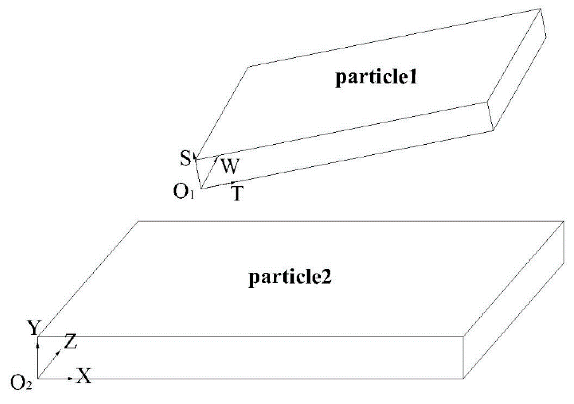
Based on the well-known London theory for attractive energy between two-unit molecules, the theories for attractive energy between two macro-bodies have been developed significantly by Hamaker, de Boer, Casimir and Polder, and Lifshitz [1,6,17]. Following these classical theories, Anandarajah and Chen put forward a combined theory that was referred to as Hamaker-de Boer-Lifshitz theory in order to account for the retardation effect in a condensed system as well as the effect of geometry of macro-bodies [17]. To calculate the van der Waals forces between neighboring clay particles reasonably and efficiently, the geometry of the clay particle has been assumed to be a cubic plate. Furthermore, the calculation of van der Waals forces between two arbitrary plates as shown in Figure 1, in which two rectangular Cartesian coordinate systems O1TSW and O2XYZ moving with plate1 and plate2, respectively, are defined, was simplified into that between a finite plate and an infinite plate which is referenced to as a wall as shown in Figure 2. According to the ideal plate-wall model shown in Figure 2 where Z-axes and W-axes are assumed to be parallel to each other, a close-form formula for van der Waals force was obtained [17], which has been used widely in the later DEM simulations of clays [13,14,15,18,19] due to the high efficiency of close form solution.
The analytical formula of the van der Waals forces for the above ideal plate-wall model is [17]
where A is the Hamaker constant 1.59 × 10⁻²⁰ J, c is a constant dependent on the characteristic length of interaction (49.363 nm is taken throughout the present study following [17]), w1, d1 and L1 are the width, thickness, and length of plate1, respectively, d2 is the thickness of the wall (i.e., plate2 in Figure 2), and d and are the minimum distance and angle between plate1 and the wall, respectively. It was also shown that the force Fpw in Equation (1) is in the direction of Y-axes, i.e., perpendicular to the selected wall shown in Figure 2 [17]. Anandarajah and Chen further gave the similar formulas of the coordinates of action of Fpw on plate1, which are not presented here for space reasons.
Chen adopted a rigorous method of adding van der Waals forces between all the pairs of molecules over these two plates [16]. By this method, an expression of a multi integral instead of analytical formula like Equation (1) was obtained. To simplify the calculation, Chen assumed that Z-axes and W-axes shown in Figure 3 were parallel to each other. As a result, the relative inclination between these two plates can be determined by one angle α. The expression of van der Waals force acting on plate2 in Figure 3 are
where V1, V2 denote the volume of plate1 and plate2, r is the distance between an arbitrary molecule A(x,y,z) in plate2 and B(t,s,w) in plate1, denotes the direction of the vector AB with respect to O2XYZ coordinate system, D is the minimum distance between the two plates as shown in Figure 3, d2 is the thickness of plate2, and lx and lz are the coordinates of O1 in the O2XYZ system. The expressions of the locations of total force on the two plates C1 and C2 as shown in Figure 3 were also obtained [16], which are not present here for space reasons.
The calculation related to Equation (2) is too time consuming [16] to be used in practical DEM simulation. To reduce computation effort, Chen put forward an approximation method of superposition [16]. However, the method of superposition involves the solutions of nine equations, among which there is a nonlinear one. The reason why the abovementioned analytical solution based on the ideal plate-wall model instead of the approximation method is widely used in DEM simulations is most likely its simplicity.
However, there is a dilemma of how to choose a proper ideal wall in the two plates shown in Figure 1. It seems that either of the two plates can be chosen as the ideal wall. Nevertheless, it can be deduced that different choices result in different magnitudes as well as directions of total van der Waals forces between neighboring clay particles. Therefore, the present study aims to give reasonable advice for the proper use of the ideal plate-wall model by comparing its solutions and those of a more rigorous plate-plate model.
The remainder of this paper is organized as follows. Firstly, the integral expression of a rigorous plate-plate model in which two plates are arbitrarily located in three-dimensional space is given and its numerical solution is verified. Then, the effects of choice of the ideal wall in two plates on the calculated van der Waals force are investigated systematically for various contact types including face-face, face-edge contact, and so on. Finally, according to the corresponding analysis, necessary advice for the reasonable use of the ideal-wall model is given.
2. New Rigorous Plate-Plate Model and Its Numerical Solution
2.1. Van der Waals Force for the New Rigorous Plate-Plate Model
For the model of two arbitrarily located plates as shown in Figure 3, the coordinates of any molecule B(xB, yB, zB) in plate1 with respect to the O2XYZ system are related to the counterpart B(t,s,w) in the O1TSW system by a rotational matrix instead of only one angle α as described in Chen’s plate-plate model.
in which is the coordinates of O1 with respect to O2XYZ system, R12 is the rotational matrix, and the element of R12, rij denotes the directional cosine between i axes and j axes. Accordingly, the distance between an arbitrary point A(x,y,z) in plate2 and B(t,s,w) in plate1 is
and the direction of the vector AB with respect to O2XYZ coordinate system is
The expression of van der Waals force acting on plate2 in the present model can be obtained by substituting Equations (4) and (5) into Equation (2). As can be seen, Chen’s plate-plate model can be regarded as a special case of the present plate-plate model.
2.2. Numerical Solution of van der Waals Force of the New Model
It can be noticed that multiple integral is involved in the numerical solution of Equation (2). Due to the highly nonlinear integrand which is a function of Equations (4) and (5), a reasonable numerical procedure has to be elected to obtain the accurate solutions. It should be noted that Monte Carlo [20] and quasi-Monte Carlo [21] methods have been adopted by the author to address this problem. However, plenty of calculations indicated that the integral values are sensitive to the selection of random sample points, and the solutions are often unable to converge with the increasing number of sample points. An optimized Cotes integral method [22] is elected on a trial and error basis.
According to the used integral method [22], the numerical precision of multiple integrals over a six-dimensional cubic domain can be guaranteed by continuous division of the integral interval in the following way: the interval [ai,bi] is divided into 4mi equal subintervals, then each subinterval can be divided into five equal parts repeatedly until the desired precision has been reached. The corresponding numerical integral formula is
in which
2.3. Verification of the Obtained Numerical Solution
An example of the present model is taken to verify the numerical solution. In this example, the two plates have the same length and width of 0.1 μm and the same thickness of 0.01 μm, they are parallel to each other, and the distance between them is 0.001 μm. The example can equally be described in terms of necessary quantities introduced previously, d1 = d2 = 0.01, D = 0.001, l1 = l2= w1 = w2 = 0.1, lx = lz = 0, α = 0 (the unit μm is omitted for brevity).
This example is solved numerically in both frameworks of Chen’s model and the present model using the abovementioned Cotes integral method. The integral intervals along the length and width of the both plates are divided into 4m subintervals, and those along the thickness of the both plates are divided into 0.4m subintervals. Nine values of m ranging from 5 to 35 are taken. At the same time, the example is also solved using the ideal plate-wall formula Equation (1). We used Fppy and Fpwy to denote the calculated force based on the plate-plate and plate-wall model, respectively. All the forces are along the Y-axes since the two plates are parallel to each other.
Figure 4 presents the numerical results. It can be seen that the solutions based on Chen’s plate-plate model and those on the present model are exactly the same since the former is a special case of the latter, and the integral converges when the number of division m exceeds 27.5. The converged ratio of Fppy to Fpwy is about 0.3, which means that the ideal plate-wall model overestimates the total van der Waals force between neighboring clay particles.
The possible reason for the overestimation is that the ideal plate-wall model treats one of the two finite plates as an infinite plate. To verify the speculation, more calculations in which the size of plate1 is fixed and that of plated2 increases gradually while the two plates are parallel to each other with the line linking the centers of the two plates along the normal of the plate were carried out. Table 1 presents the calculated results. It can be seen that the calculated force based on the present model increased with the increasing size of plate2. The ratio of Fppy to Fpwy is about 0.93 when the area of plate2 is 106 times that of plate1.
3. Effect of the Choice of Ideal Wall
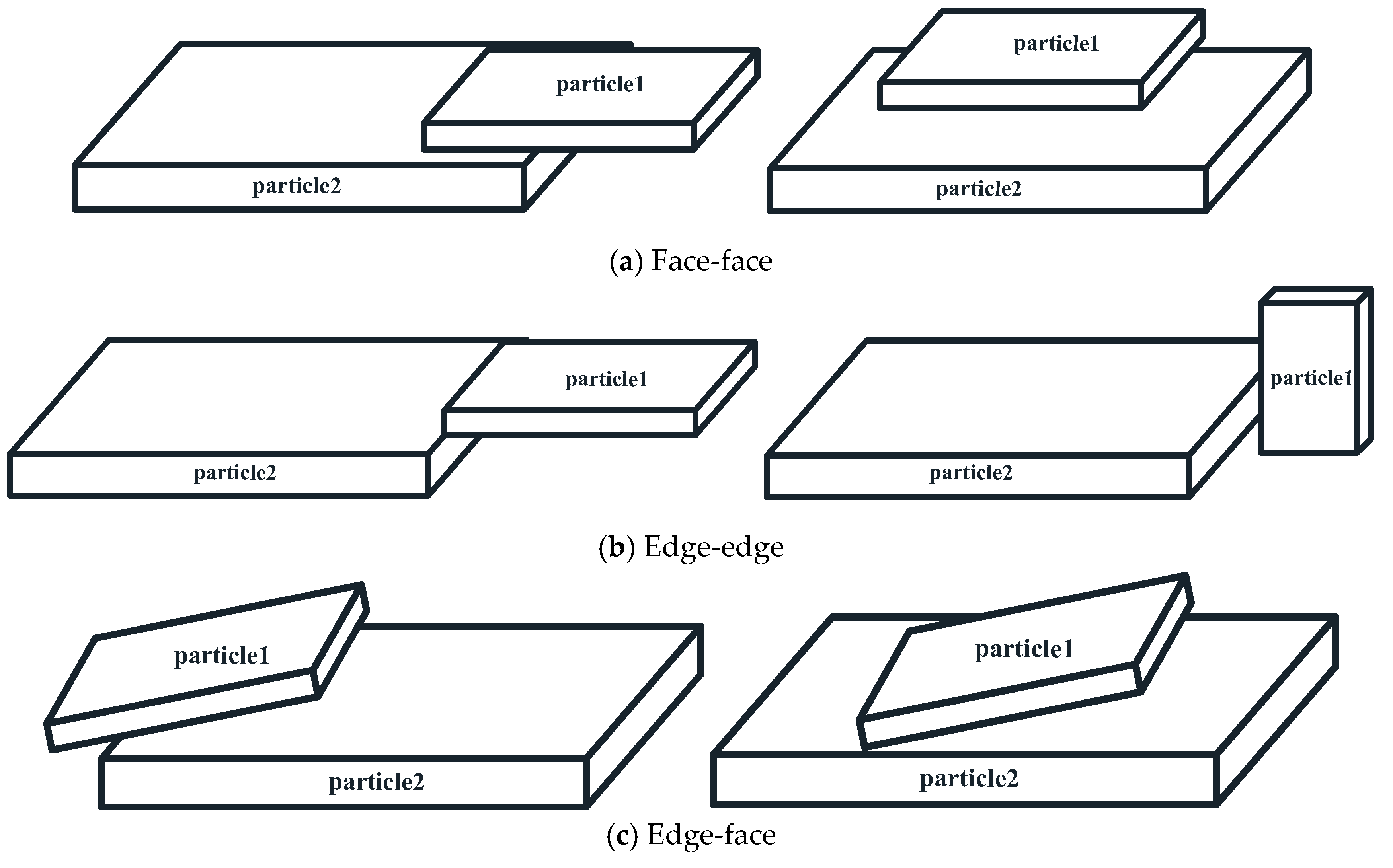
Three basic contact types are shown schematically in Figure 5, among which two plates are parallel to each other in the face-face type. The effect of the choice of the ideal wall will be investigated separately in this section.
3.1. Face-Face Type
For this type, we only focus on the effect of the choice of ideal wall on the magnitude of the calculated van der Waals force since the force is always along the direction perpendicular to the face, i.e., Y-axis shown in Figure 6 in which two specific cases of face-face type are illustrated. All the endpoints of particle1 are projected on the particle2 in case (a), while only part of them are projected on the partilce2 in case (b). The geometric parameters related the two plates are: l1 = w1 = 0.1, l2 = w2 = 0.2, d1 = d2= 0.01. lx and lz are shown in Figure 6. The distance between the two plates, D, increases from 1 nm to 10 nm.
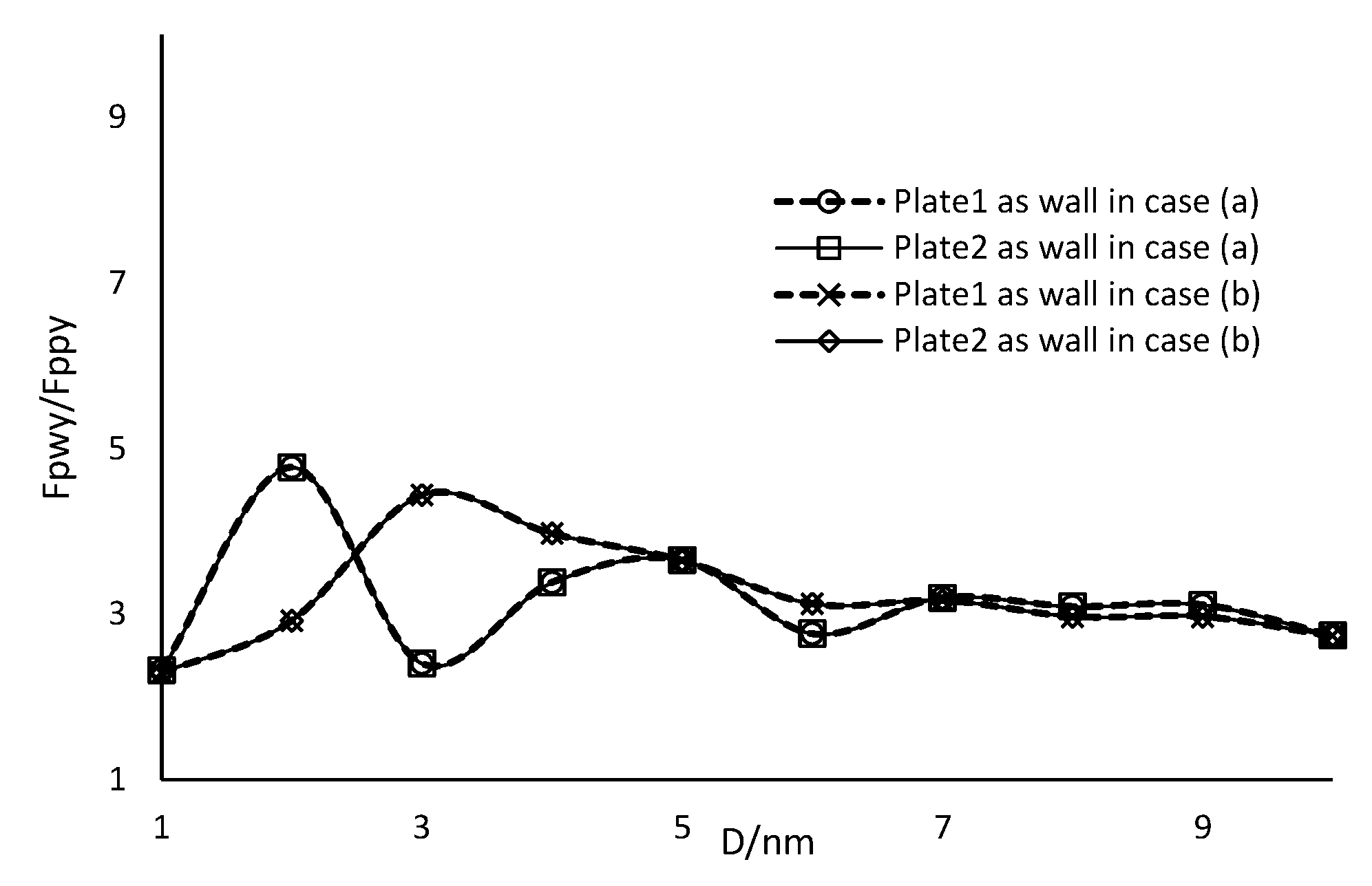
Figure 7 presents the calculated ratios of Fpwy to Fppy of the two specific cases shown in Figure 6. For each case, two different choices of the ideal wall were made. It can be seen that the calculated Fpwy corresponding to the choice of treating plate1 as the ideal wall is larger than that of plate2 as the ideal wall, and the ratio of Fpwy to Fppy corresponding to case (a) is larger than that to case (b). The reason why the calculated Fpwy corresponding to plate1 being the wall is much larger is that plate2 has a larger area. Therefore, it seems like the choice of the ideal wall has a remarkable effect on the calculated force depending on the geometric configuration of the two plates.
To reduce the overestimation of the ideal plate-wall model as much as possible, it is reasonable to choose the plate with a smaller area as the ideal wall. For the specific cases shown in Figure 6, or two-dimensional cases, the following procedure is put forward. After choosing one plate i as the ideal wall, the other plate j of the two plates is projected on the chosen plate. Then the projected length and width are regarded as the new counterparts of the plate j. The new sizes are denoted by the variables with an apostrophe shown in Figure 8 and Figure 9 that present the projection for the two specific cases, as plate1 and plate2 are chosen as the ideal wall, respectively.
It can be seen from Figure 10 that the calculated forces are relatively small and the same no matter which plate is chosen as the ideal wall. Therefore, for the specific three-dimensional cases in which the projection of one plate on the other plate is a rectangle or two-dimensional case, the proposed projection procedure can eliminate the adverse effect of the choice of the ideal wall.
3.2. Edge-Edge Type
Figure 11 illustrates two specific cases of edge-edge type. The geometric parameters related to the two plates are the same as those shown in face-face type: l1 = w1 = 0.1, l2 = w2 = 0.2, d1 = d2 = 0.01. Two specific cases of relative positions of the two plates are shown in Figure 11 where various distance between plates is along Y direction in case (a) and X direction in case (b). According to the previous observation, the calculated force for these cases will be small since the corresponding projection area is small.
Figure 12 presents the ratios of the plate-plate solutions of the two specific cases of edge-edge type, Fee, to that of case (a) of face-face type shown in Figure 6, Fff, while keeping the same distance between two plates. It can be seen that the van der Waals forces in the case of the edge-edge type are much smaller than those of face-face type under the same conditions of plate size and distance between plates. So, it seems that van der Waals force for the case of edge-edge type can be ignored in DEM simulations. Therefore, the effect of the choice of the ideal wall will not be analyzed further.
3.3. Edge-Face Type
3.3.1. Magnitude of the Calculated Forces
Figure 13 illustrates two specific cases of edge-face type in which the W-axes is parallel to the Z-axes and the projection area is a rectangle. The geometric parameters related the two plates are: l1 = w1 = 0.1, l2 = w2 = 0.2, d1 = d2 = 0.01 in case (a); l1 = 0.2, w1 = 0.1, l2 = w2 = 0.2, d1 = d2= 0.01 in case (b).
Observations on the aspect of the effect of ideal wall choice are similar as those in the case of face-face type. Therefore, for the two specific cases shown in Figure 13, the abovementioned projection procedure has been performed before calculating the relevant plate-wall solutions as illustrated in Figure 14 and Figure 15.
It can be seen form Figure 16 that unlike the results of the face-face type, the calculated forces are different for the different choice of the ideal wall even after the abovementioned projection procedure has been performed. For the case (a) shown in Figure 13, the calculated force corresponding to plate2 being the wall is larger than that to plate1 being the wall, and the difference between the calculated forces corresponding to the different choices for α = 30° is smaller than that for α = 45°. However, for the case (b) shown in Figure 13, the calculated force corresponding to plate2 being the wall is smaller than that to plate1 being the wall, while the difference between the calculated forces corresponding to the different choices for α = 30° is smaller than that for α = 45°. The above differences reflect the effect of the new length and distance after projection as shown in Figure 14 and Figure 15. Comparing the above observations to the geometric parameters shown in Figure 14 and Figure 15, it can be concluded that the change in the distance instead of length due to the different choice of ideal wall has the critical influence on the calculated forces.
Therefore, to reduce the overestimation of the ideal plate-wall model as much as possible, a reasonable choice of the ideal wall means a smaller distance between the two plates for the case of edge-face contact type.
3.3.2. Direction and Location of the Calculated Forces
The case (a) shown in Figure 13 has been chosen to investigate the difference in the direction and location of the calculated forces based on the ideal plate-wall and plate-plate wall model. As illustrated in the last subsection, for the studied case, choosing plate1 as the wall led to a smaller calculated force. Therefore, the calculations based on the ideal plate-wall model treat plate1 as the ideal wall while the distance between the two plates is kept 0.001 μm, and the angle α increases from 15° to 75°.
According to the ideal plate-wall model [17], the direction of the total van der Waals force is perpendicular to the ideal wall. For the studied case, the direction is just along the S-axes shown in Figure 13 (a). To show the direction of the calculated force based on the plate-plate model, the coordinate components of the force based on plate-plate model are presented in Table 2. The last column is the direction of the calculated force based on the plate-wall model, with plate1 being the wall.
When plate2 is treated as the wall, the direction of the calculated force is just along the Y-axes, shown in Figure 13 (a). It can be seen from Table 2 that the direction corresponding to plate-plate model is somewhere in between the direction corresponding to plate-wall model, with plate1 being a wall and plate2 being a wall. In addition, it can be seen that the difference in the directions between plate-plate and plate-wall model changes nonlinearly with the increasing angle between two plates. However, comparing with the traditional plate-wall model widely used in DEM [13,14,15,17,18,19], it would be reasonable if the direction of the total van der Waals force is taken as the average of the directions corresponding to plate-wall model with plate1 being a wall and plate2 being a wall.
Table 3 shows the difference between the location of the calculated force based on the plate-plate model and that of the plate-wall model. Plate2 in Figure 13 (a) is treated as the wall and the location is the acting point of the calculated force on the plate2. We use Xpp and Xpw to denote the X-coordinate of the acting point based on the plate-plate and plate-wall model, respectively. The other variables in Table 3 denote the relevant quantity in a similar way. It can be seen that the difference in the X-coordinate between the plate-plate and plate-wall model is most significant, the Z-coordinate is smallest, and the Y-coordinate is in between. This difference in the X-coordinate increases nonlinearly with the increasing angle between two particles. However, the projection length and the calculated van der Waals force becomes small with the increasing angle between two particles. Therefore, the influence of the above difference in the location of calculated force on the calculated moment will not be as large as the difference itself shown in Table 3.
4. Conclusions
Review on the literature related to the calculation of van der Waals force between two clay particles shows that the ideal plate-wall model has been widely used in clay DEM simulations. This study developed a plate-plate model without any assumption about the relative location of the two plates, and an optimized Cotes integration method has been used to calculate the van der Waals force numerically. Through the comparison of the calculated results based on the plate-wall model and the plate-plate model, the effect of the choice of the ideal wall has been investigated.
The calculated results show that for the face-face contact type, it is reasonable to choose the plate with a smaller area as the ideal wall in general. For the three-dimensional cases which can be simplified into two-dimensional cases, the projection procedure is advised before using the plate-wall model. This procedure chooses one plate i as the ideal wall, the other plate j of the two plates is projected on the chosen plate. Then the projected length and width are treated as the new counterparts of the plate j. The aim of the above is to reduce the overestimation of the ideal plate-wall model as much as possible.
The van der Waals forces in the case of edge-edge type are much smaller than those of face-face type. It seems reasonable that van der Waals force for the case of edge-edge type can be ignored in DEM simulations.
In additional, for the edge-face contact type, a reasonable choice of the ideal wall is to choose one plate as the ideal wall so that there is a smaller distance between the two plates. It is reasonable that the direction of the total van der Waals force is taken as the average of the directions corresponding to the plate-wall model, with plate1 being a wall and plate2 being a wall. The difference in the location of the calculated force based on the plate-wall model and plate-plate model increases nonlinearly with the increasing angle between clay particles. It has limited effect on the calculated moment.
Author Contributions
Conceptualization, X.-Y.S. and K.Z.; Methodology, X.-Y.S. and W.-X.Q.; Software, W.-X.Q. and X.-Y.S.; Validation, X.-Y.S. and K.Z.; Formal Analysis, X.-Y.S. and K.Z.; Investigation, Q.-Y.Z.; Resources, G.-Q.Z.; Data Curation, K.Z.; Writing—Original Draft Preparation, X.-Y.S., K.Z. and W.-X.Q.; Writing—Review & Editing, X.-Y.S. All authors have read and agreed to the published version of the manuscript.
Funding
The authors gratefully acknowledge the financial support provided by fundamental research funds for the central universities (2017xkqy052).
Conflicts of Interest
The authors declare no conflict of interest.
References
- Israelachvili, J.N. Intermolecular and Surface Forces, 3rd ed.; Academic Press: Amsterdam, The Netherlands, 2011. [Google Scholar]
- Yu, Z.H.; Zheng, Y.Y.; Zhang, J.B.; Zhang, C.Z.; Ma, D.H.; Chen, L.; Cai, T.Y. Importance of soil interparticle forces and organic matter for aggregate stability in a temperate soil and a subtropical soil. Geoderma 2020, 362, 114088. [Google Scholar] [CrossRef]
- Xiong, J.; Liu, X.J.; Liang, L.X.; Wei, X.C.; Xu, P. Investigation of the factors influencing methane adsorption on illite. Energy Sci. Eng. 2019, 7, 3317–3331. [Google Scholar] [CrossRef]
- Ndabambi, M.; Kwon, J.H. Benzalkonium ion sorption to peat and clays: Relative contributions of ion exchange and van der Waals interactions. Chemosphere 2020, 247, 125924. [Google Scholar] [CrossRef] [PubMed]
- Hattab, M.; Chang, C.S. Interaggregate forces and energy potential effect on clay deformation. J. Eng. Mech. 2015, 141, 04015014. [Google Scholar] [CrossRef] [Green Version]
- Mitchell, J.K.; Soga, K.I. Fundamentals of Soil Behavior; John Wiley & Sons: Hoboken, NJ, USA, 2005. [Google Scholar]
- Amarasinghe, P.M.; Anandarajah, A.; Ghosh, P. Molecular dynamic study of capillary forces on clay particles. Appl. Clay Sci. 2014, 89, 170–177. [Google Scholar] [CrossRef]
- Tournassat, C.; Bourg, I.C.; Holmboe, M.; Sposito, G.; Steefel, C.I. Molecular dynamics simulations of anion exclusion in clay interlayer nanopores. Clays Clay Miner. 2016, 64, 374–388. [Google Scholar] [CrossRef] [Green Version]
- Underwood, T.R.; Bourg, I.C. Large-scale molecular dynamics simulation of the dehydration of a suspension of smectite clay nanoparticles. J. Phys. Chem. C 2020, 124, 3702–3714. [Google Scholar] [CrossRef] [Green Version]
- Ebrahimi, D.; Pellenq, R.J.M.; Whittle, A.J. Mesoscale simulation of clay aggregate formation and mechanical properties. Granul. Matter 2016, 18, 49. [Google Scholar] [CrossRef] [Green Version]
- Sjoblom, K.J. Coarse-grained molecular dynamics approach to simulate clay behavior. J. Geotech. Geoenvironmental Eng. 2016, 142, 06015013. [Google Scholar] [CrossRef]
- Cundall, P.A.; Strack, O.D.L. A discrete numerical model for granular assemblies. Geotechnique 1979, 29, 47–65. [Google Scholar] [CrossRef]
- Jaradat, K.A.; Abdelaziz, S.L. On the use of discrete element method for multi-scale assessment of clay behavior. Comput. Geotech. 2019, 112, 329–341. [Google Scholar] [CrossRef]
- Anandaraiah, A. Numerical simulation of one-dimensional behaviours of a kaolinite. Geotechnique 2000, 50, 509–519. [Google Scholar] [CrossRef]
- Yao, M.; Anandarajah, A. Three-dimensional discrete element method of analysis of clays. J. Eng. Mech. 2003, 129, 585–596. [Google Scholar] [CrossRef]
- Chen, J. Physico-Chemical Analysis of Contaminated Clay; The Johns Hopkins University: Baltimore, MD, USA, 1996. [Google Scholar]
- Anandarajah, A.; Chen, J. Van Der Walls attractive force between clay particles in water and contaminants. Soils Found. 1997, 37, 27–37. [Google Scholar] [CrossRef] [Green Version]
- Katti, D.R.; Matar, M.I.; Katti, K.S.; Amarasinghe, P.M.A. Multiscale modeling of swelling clays: A computational and experimental approach. KSCE J. Civ. Eng. 2009, 13, 243–255. [Google Scholar] [CrossRef]
- Anandarajah, A.; Amarasinghe, P.M. Discrete-element study of the swelling behaviour of Na-montmorillonite. Geotechnique 2012, 63, 674–681. [Google Scholar] [CrossRef]
- Ueberhuber, C.W. Numerical Computation 2: Methods, Software, and Analysis; Springer: Berlin, Germany, 1997. [Google Scholar]
- Dick, J.; Kuo, F.Y.; Sloan, I.H. High-dimensional integration: The quasi-Monte Carlo way. Acta Numer. 2013, 22, 133–288. [Google Scholar] [CrossRef]
- Zhu, L. High-dimensional Cotes optimization integral numerical method and estimation of other terms. Coll. Math. 2008, 24, 75–79. [Google Scholar]
Figure 1.
Two arbitrary neighboring platy clay particles.

Figure 2.
Schematic diagram of the ideal plate-wall system.

Figure 3.
Model of two arbitrary finite plates in three-dimensional space.

Figure 4.
Comparison of numerical solutions based on Chen’s plate-plate model and the present model.
Figure 4.
Comparison of numerical solutions based on Chen’s plate-plate model and the present model.

Figure 5.
Schematic diagram of contact types in three-dimensional space.

Figure 6.
Two specific cases of face-face contact


Figure 7.
Comparison of the calculated forces with different choices of the ideal wall.

Figure 8.
Schematic diagram of the projection step as plate1 is treated as the wall.

Figure 9.
Schematic diagram of the projection step as plate2 is treated as the wall.

Figure 10.
Comparison of the calculated force of different choices based on projection procedure.

Figure 11.
Two specific cases of edge-edge contact.

Figure 12.
Comparison of the calculated force of edge-edge and face-face type.

Figure 13.
Two specific cases of edge-face contact.

Figure 14.
Schematic diagram of the projection step treating plate1 as the wall.

Figure 15.
Schematic diagram of the projection step treating plate2 as the wall.

Figure 16.
Comparison of the calculated forces of different choices for the cases of edge-face type.
Figure 16.
Comparison of the calculated forces of different choices for the cases of edge-face type.


Table 1.
Comparison of van der Waals force calculated based on plate-wall model and the present model.
Table 1.
Comparison of van der Waals force calculated based on plate-wall model and the present model.
| α = 0, d1 = d2 = 0.01, D = 0.001, l1 = w1 = 0.1, l2 = w2 | |||
|---|---|---|---|
| l2/l1 | Fpwy/10−9N | Fppy/10−9N | Fppy/Fpwy |
| 1(lx = lz = 0, m = 27.5) | 8.10 | 2.84 | 0.35 |
| 2(lx = lz = 0.05, m = 27.5) | 3.49 | 0.43 | |
| 3(lx = lz = 0.1, m = 27.5) | 3.87 | 0.48 | |
| 10(lx = lz = 0.45, m = 27.5) | 4.58 | 0.57 | |
| 100(lx = lz = 4.95, m = 27.5) | 5.91 | 0.73 | |
| 1000(lx = lz= 0, m = 49.95, m = 37.5) | 7.56 | 0.93 | |
Table 2.
Comparison of the directions of Van der Waals forces based on plate-plate and plate-wall model.
Table 2.
Comparison of the directions of Van der Waals forces based on plate-plate and plate-wall model.
| α | Fppx/10−9N | Fppy/10−9N | Fppz/10−9N | Fppx/Fppy | Fpwx/Fpwy |
|---|---|---|---|---|---|
| 15° | −4.02 × 10⁻³ | 2.86 × 10⁻² | 5.85 × 10⁻⁵ | −0.141 | −0.268 |
| 30° | −2.78 × 10⁻³ | 1.37 × 10⁻² | 2.58 × 10⁻⁵ | −0.203 | −0.577 |
| 45° | −2.32 × 10⁻³ | 9.60 × 10⁻³ | 1.75 × 10⁻⁵ | −0.241 | −1.0 |
| 60° | −2.33 × 10⁻³ | 8.15 × 10⁻³ | 1.54 × 10⁻⁵ | −0.286 | −1.732 |
| 75° | −2.80 × 10⁻³ | 7.86 × 10⁻³ | 1.62 × 10⁻⁵ | −0.357 | −3.732 |
Table 3.
Comparison of the locations of Van der Waals forces based on plate-plate and plate-wall model.
Table 3.
Comparison of the locations of Van der Waals forces based on plate-plate and plate-wall model.
| α | Xpw/Xpp | Ypw/Ypp | Zpw/Zpp |
|---|---|---|---|
| 15° | 0.845424352 | 0.987905290 | 1.000105178 |
| 30° | 1.067378334 | 0.989210020 | 1.000041638 |
| 45° | 1.715227995 | 0.966569502 | 1.000008018 |
| 60° | 3.244969855 | 0.879831892 | 1.00000768 |
| 75° | 7.722029849 | 0.696792073 | 1.000036639 |
Publisher’s Note: MDPI stays neutral with regard to jurisdictional claims in published maps and institutional affiliations. |
© 2020 by the authors. Licensee MDPI, Basel, Switzerland. This article is an open access article distributed under the terms and conditions of the Creative Commons Attribution (CC BY) license (http://creativecommons.org/licenses/by/4.0/).
Share and Cite
MDPI and ACS Style
Shang, X.-Y.; Zhao, K.; Qian, W.-X.; Zhu, Q.-Y.; Zhou, G.-Q. On the Calculation of Van der Waals Force between Clay Particles. Minerals 2020, 10, 993. https://0-doi-org.brum.beds.ac.uk/10.3390/min10110993
AMA Style
Shang X-Y, Zhao K, Qian W-X, Zhu Q-Y, Zhou G-Q. On the Calculation of Van der Waals Force between Clay Particles. Minerals. 2020; 10(11):993. https://0-doi-org.brum.beds.ac.uk/10.3390/min10110993
Chicago/Turabian StyleShang, Xiang-Yu, Kang Zhao, Wan-Xiong Qian, Qi-Yin Zhu, and Guo-Qing Zhou. 2020. "On the Calculation of Van der Waals Force between Clay Particles" Minerals 10, no. 11: 993. https://0-doi-org.brum.beds.ac.uk/10.3390/min10110993
Note that from the first issue of 2016, this journal uses article numbers instead of page numbers. See further details here.