Article

Penetration Grouting Mechanism of Time-Dependent Power-Law Fluid for Reinforcing Loose Gravel Soil

1
Faculty of Public Safety and Emergency Management, Kunming University of Science and Technology, Kunming 650093, China
2
Faculty of Land Resources Engineering, Kunming University of Science and Technology, Kunming 650093, China
3
Key Laboratory of Geological Disaster Risk Prevention and Control and Emergency Disaster Reduction of Ministry of Emergency Management of the People’s Republic of China, Kunming 650093, China
4
Key Laboratory of Early Rapid Identification, Prevention and Control of Geological Diseases in Traffic Corridor of High Intensity Earthquake Mountainous Area of Yunnan Province, Kunming 650093, China
5
Institute of Mountain Hazards and Environment, Chinese Academy of Sciences, Chengdu 610041, China
6
School of Computer Science and Engineering, University of Electronic Science and Technology of China, Chengdu 611731, China
7
Beijing Fibote Photoelectric Technology Co., Ltd., Beijing 100083, China
8
PipeChina SouthWest Pipeline Company, Chengdu 610041, China
9
The Third Engineering Co., Ltd., of China Railway Seventh Bureau Group Corporation, Xi’an 710032, China
10
Yunnan Aerospace Engineering Geophysical Detecting Co., Ltd., Kunming 650217, China
11
Yunnan Institute of Geological Environment Monitoring, Kunming 650216, China
12
Kunming Survey, Design and Research Institute Co., Ltd., of CREEC, Kunming 650200, China
13
Center for Hydrogeology and Environmental Geology, China Geological Survey, Baoding 071051, China
*
Author to whom correspondence should be addressed.
Submission received: 7 October 2021 / Revised: 1 November 2021 / Accepted: 6 December 2021 / Published: 8 December 2021

Abstract

:
The time-dependent behavior of power-law fluid has a significant influence on the grouting effects of reinforcing loose gravel soil. In this paper, based on basic rheological equations and the time-dependent behavior of rheological parameters (consistency coefficient and rheological index), rheological equations and penetration equations of time-dependent power-law fluid are proposed. Its penetration grouting diffusion mechanism for reinforcing loose gravel soil was then theoretically induced. A set of indoor experimental devices for simulating penetration grouting was designed to simulate the penetration grouting of power-law fluid with different time-dependent behaviors for reinforcing loose gravel soil. Then, relying on the COMSOL Multiphysics platform and Darcy’s law, three-dimensional numerical calculation programs for this mechanism were obtained using secondary-development programming technology. Thus, the numerical simulations of the penetration grouting process of power-law fluid with different time-dependent behaviors for reinforcing loose gravel soil were carried out. This theoretical mechanism was validated by comparing results from theoretical analyses, indoor experiments, and numerical simulations. Research results show that the three-dimensional numerical calculation programs can successfully simulate the penetration diffusion patterns of a time-dependent power-law fluid in loose gravel soil. The theoretical calculation values and numerical simulation values of the diffusion radius obtained from this mechanism are closer to indoor experimental values than those obtained from the penetration grouting diffusion theory of power-law fluid without considering time-dependent behavior. This mechanism can better reflect the penetration grouting diffusion laws of a power-law fluid in loose gravel soil than the theory, which can provide theoretical support and guidance for practical grouting construction.

1. Introduction

Gravel soil is a kind of loose, coarse fragment accumulation formed in the Quaternary, which is widely distributed in natural strata such as colluvium deposits, rockfills, alluvial deposits, and glacial tills, among others [1]. Gravel soil is generally composed of cohesive soil and pebble, which has the characteristics of exhibiting a loose structure, large pores between particles, uneven distribution, and low cohesion [2]. Many geological disasters formed by gravel soil, such as landslides, collapses, debris flows, mine slopes, and dammed lakes, are induced by earthquake actions and human activities and cause heavy casualties and huge property losses [3,4,5,6,7,8,9,10,11,12]. To study the engineering characteristics of gravel soil and reduce the occurrence of disasters, Shi et al. proposed a simple approach to evaluate the strength parameters of sand-like colluvium [13]. Chen et al. studied the effect of clay content on the strength of gravel [14]. Li studied the strength of sandstones under the wetting–drying treatment and high temperature [15,16]. Do et al. discussed the static liquefaction of gravel soil [17]. Many researchers aim to study the physical and mechanical properties of gravel, but few research outputs are focusing on the reinforcement of gravel soil.
Penetration grouting technology is often used to reinforce gravel strata to improve its strength and stability. The penetration grouting technique is one of the earliest geotechnical construction techniques used in the field of grouting. It is often used to reinforce the loose gravel stratum to improve strength and stability. As early as 1802, French Civil Engineer Charles Berlghy applied it to the repair of the Dieppe scouring sluice [18,19]. Due to minute influence on the injected medium during the grouting process, it has been widely used in architecture, highways, railways, subways, mines, tunnels, hydropower, military, and other engineering fields around the world [20,21,22,23,24,25,26,27].
In general, grouting fluid can be classified as a Newtonian fluid, Bingham fluid, and power-law fluid according to different rheological constitutive equations [28,29,30]. Among them, Newtonian fluid is the first kind of material for the study of the penetration grouting mechanism. In 1938, Maag deduced the earliest penetration grouting theory—the Maag formula—by assuming that Newtonian fluid penetrated and diffused spherically in an isotropic medium [22]. Karol, Huang, Yang, Raffle, and Greenwood et al. carried out studies based on the Maag formula to study grouting theory [31,32,33]. Li and Yang, respectively, discussed the expression of the column and column-hemisphere penetration grouting diffusion radius of a Newtonian fluid in porous media [34,35]. Baker, Hassler, Funehag et al., and Amadei et al. analyzed the diffusion mechanism of Newtonian fluid in fractures of rock and soil [36,37,38,39]. In addition, Hassler, Zhang, Ding, and Yang also carried out studies on the time-dependent penetration grouting theory of Newtonian fluid [37,40,41,42].
As for the penetration grouting diffusion mechanism of Bingham fluid, many theoretical investigations have been conducted to better understand the influence factors during grouting. Liao, Fan, and Tekin et al. analyzed the injectability of cement grouts in porous media [43,44,45]. Saada, Kim, Bouchelaghem, Eriksson, Chupin, Maghous, and Yoon discussed the penetration grouting mechanism of porous media considering the percolation effect [46,47,48,49,50,51,52]. Uddin, Dayakar, and Yang studied the penetration diffusion laws of Bingham fluid in sandy stratums and sand (gravel) stratums, respectively [18,53,54]. Bolisetti and Costas et al. explored the penetration grouting mechanism of chemical grouts in porous media [55,56,57]. Ye studied the penetration grouting diffusion model for shield tunnels based on Bingham fluid [58]. Zhou analyzed the penetration diffusion model by considering the pore tortuosity effect [59]. Lombardi, Amadei, Lee, Liu, Sun, Mohammed, Wallner, and Zhou discussed the flowing laws of Bingham fluid in rock fractures [59,60,61,62,63,64,65,66]. Gustafson constructed the migration equation of Bingham grouts for a single plate fracture under constant pressure grouting conditions [67]. Pedrotti and Sui et al. researched the fracture grouting diffusion mechanism under hydrodynamic conditions [68,69]. Hassler, Mohamme, Kim, Li, Zhang, and Yang et al. also conducted studies on the penetration mechanism of time-dependent Bingham fluid [37,40,47,65,70,71,72,73].
In terms of the penetration grouting mechanism for power-law fluid, not many studies can be found in the available literature. Yang and Zhang et al. studied the penetration characteristics of a power-law fluid in both porous media and fractured media [74,75]. Yang et al. discussed the penetration grouting mechanism of a power-law fluid in porous media [76,77]. Ye and Fu carried out some studies on the penetration diffusion mechanism of power-law fluid for shield tunnel grouting [58,78]. Zhou constructed the penetration diffusion model of power-law fluid by considering pore tortuosity effect of the porous media [59]. Zhang analyzed the grouting diffusion theory of power-law fluid in the fractures of rock and soil [79]. Yang et al. studied the penetration grouting mechanism by considering the compressive effect of time and water–cement ratio [80]. Yang et al. studied the tortuosity effect on the penetration mechanism of power-law fluids [81]. Research outputs considering the effect of the time-dependent behavior on power-law fluid are few.
In sum, although the mechanism of the Newtonian fluid and Bingham fluid have been widely studied, the field is still far from achieving a full understanding of power-law fluid during grouting. Power-law fluid is widely used in many grouting engineering practices. For example, pure cement (water–cement ratio 0.5–0.7) and clay cement grouts (clay content > 30%) used in engineering are typical power-law fluids [29,82,83]. Additionally, the time-dependent behavior has not been considered in studies on the grouting mechanism of power-law fluid. It is believed that its rheological parameters are constant throughout the entire grouting process, while its rheological parameters have typical time-dependent behaviors [29,83,84]. Therefore, the theoretical diffusion dimensions calculated from this are much larger than the actual grouting measurement values, which makes it difficult to meet the needs of engineering practice. Accordingly, in this paper, the penetration grouting mechanism of the time-dependent power-law fluid for reinforcing loose gravel soil is discussed to provide theoretical support and technical references for practical grouting engineering.

2. Penetration Grouting Mechanism of Time-Dependent Power-Law Fluid for Reinforcing Loose Gravel Soil

2.1. Rheological Equations of Time-Dependent Power-Law Fluid

The basic rheological equation of power-law fluid can be described as following the formula [29,81,82]:
τ = C γ n
As indicated by Ruan and Yang, the relationship between the consistency coefficient and rheological index of power-law fluid can be expressed in terms of time-dependent laws as illustrated in Equations (2) and (3) [24,74,75].
n ( t ) n 0
C ( t ) = C 0 e k t
By combining Equations (1)–(3), the rheological equation of time-dependent power-law fluid can be defined as follows:
τ = C ( t ) γ n ( t ) = C 0 e k t γ n 0
where τ is the shear stress; C is the consistency coefficient; C 0 is the initial consistency of time-dependent power-law fluid; C ( t ) is the consistency coefficient of time-dependent power-law fluid at t time; n is the rheological index; n 0 is the initial rheological index of time-dependent power-law fluid; n ( t ) is the rheological index of time-dependent power-law fluid at t time; γ is the shear rate; t is the grouting time; and k is the time-dependent coefficient, which can be measured by experimentations.

2.2. Penetration Equations of Time-Dependent Power-Law Fluid

As indicated by Fu and Yang [76,78], penetration equations of power-law fluid without considering time-dependent behavior can be obtained by the following Equation:
V = ( K e μ e ) 1 n ( d p d l ) 1 n
where μ e and K e can, respectively be obtained by the following Equations:
μ e = C ( 1 + 3 n ϕ r 0 n ) n 1
K e = ϕ r 0 2 2 ( n 3 n + 1 )
where V is the penetration velocity of power-law fluid without considering time-dependent behavior; p is the pressure providing for penetration; l is the displacement of penetration; K e and μ e are effective permeability and effective viscosity of power-law fluid without considering time-dependent behavior; ϕ is the porosity of the injected medium; and r 0 is the supposed parameter. It can be obtained by K = ϕ r 0 2 / 8 μ , where K and μ are, respectively, the permeability coefficient of the injected medium and the viscosity of water at the corresponding temperature.
Based on Equations (2), (3), (6), and (7), the effective permeability and effective viscosity can be obtained by the following Equations:
μ e ( t ) = C ( t ) ( 1 + 3 n ( t ) ϕ r 0 n ( t ) ) n ( t ) 1 e k t C 0 ( 1 + 3 n 0 ϕ r 0 n 0 ) n 0 1 = e k t μ e 0 = e k t μ e
K e ( t ) = ϕ r 0 2 2 ( n ( t ) 3 n ( t ) + 1 ) ϕ r 0 2 2 ( n 0 3 n 0 + 1 ) = K e 0 = K e
where μ e 0 is the initial effective viscosity of the time-dependent power-law fluid; μ e ( t ) is the effective viscosity of the time-dependent power-law fluid at t time; K e 0 is the initial effective permeability of the time-dependent power-law fluid; and K e ( t ) is the effective permeability of the time-dependent power-law fluid at t time.
Equations (8) and (9) indicate that the effective permeability of the power-law fluid changes exponentially with time and it has typical time-dependent characteristics. However, effective permeability changes little with time and reaches closer to initial effective permeability, which can be regarded as time-independent behavior.
Taking Equations (8) and (9) into (5), the penetration equation of the time-dependent power-law fluid can be obtained as follows:
V = ( K e ( t ) μ e ( t ) ) 1 n ( t ) ( d p d l ) 1 n ( t ) = e k t n 0 ( K e 0 μ e 0 ) 1 n 0 ( d p d l ) 1 n 0

2.3. Penetration Grouting Mechanism of Time-Dependent Power-Law Fluid

The following assumptions are proposed for studying the penetration grouting mechanism of time-dependent power-law fluid:
(1)
The injected medium is assumed to be isotropic and homogeneous, and the change of porosity in the process of penetration grouting can be ignored.
(2)
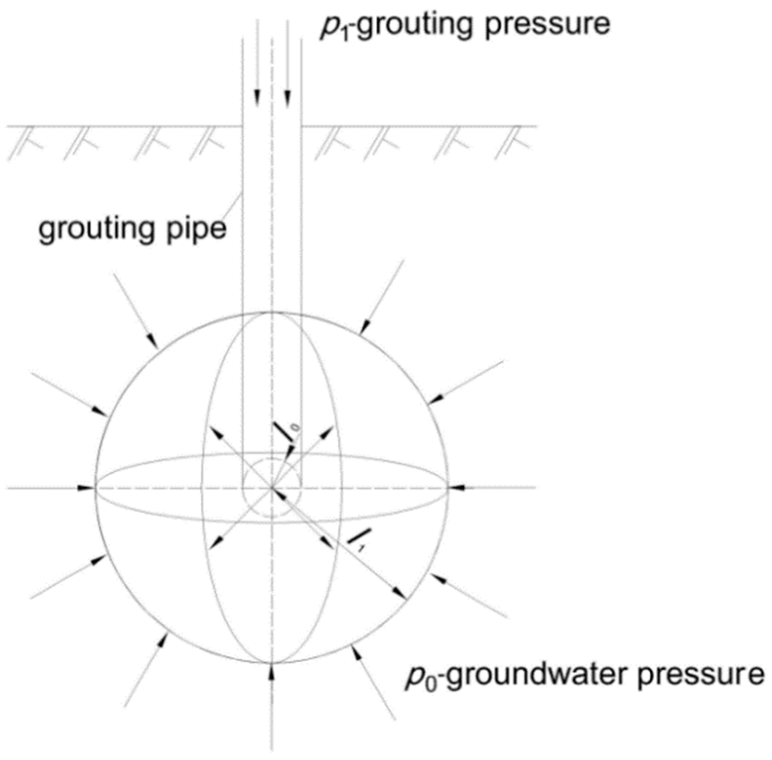
Using the tamping method, power-law fluid is injected into the injected medium from the bottom of the grouting pipe orifice and diffuses spherically.
(3)
The power-law fluid is incompressible, and the flow pattern remains unchanged during the grouting process.
(4)
The flow velocity is small. The flow state of grouts is turbulent flow in a certain small area around the grouting hole, while the flow state of other areas is laminar flow.
(5)
The gravity effect of power-law fluid is ignored during the whole grouting process.
When discussing the penetration grouting mechanism of the time-dependent power-law fluid, the penetration diffusion theoretical model used in this paper is shown in Figure 1.
In Figure 1, p 1 is the grouting pressure; p 0 is the groundwater pressure at the grouting point; l 1 is the penetration and diffusion radius of time-dependent power-law fluid after t time; and l 0 is the radius of the grouting pipe.
The grouting amount of the time-dependent power-law fluid in the grouting process meets the following Equation:
q = V A
where q is grouting flow per unit time, and A is the total surface area of the time-dependent power-law fluid in the grouting penetration diffusion area.
The total diffusion surface area A of the penetration diffusion theoretical model shown in Figure 1 is described as:
A = 4 π l 2
Taking Equations (11) and (12) into Equation (10), the following equation can be obtained:
d p = e k t μ e 0 K e 0 q 4 π n 0 l 2 n 0 d l
Integrating Equation (13) with the separation variable method and considering the boundary conditions l = l 0 , p = p 1 and the grouting amounts Q = 4 3 π l 3 ϕ , the penetration grouting diffusion mechanism of time-dependent power-law fluid for reinforcing loose gravel soil is obtained:
p l = p 1 e k t ( 1 2 n 0 ) μ e 0 K e 0 ( ϕ 3 t ) n 0 ( l 1 2 n 0 l 0 1 2 n 0 ) l 3 n 0
According to Equation (14), the penetration grouting diffusion theory of power-law fluid without considering time-dependent behavior (k = 0) is obtained:
p 1 p 0 = 1 ( 1 2 n ) μ e K e ( ϕ 3 t ) n ( l 1 1 2 n l 0 1 2 n ) l 1 3 n

2.4. Scope of Applications

The mechanism (Equation (14)) is deduced on the assumption that the flow state of the power-law fluid is laminar flow, so it does not apply to turbulent flow.
The stability coefficient Z is often used to determine the state of laminar flow or turbulent flow in the process of penetration and diffusion. When Z > 808, the penetration and diffusion process of time-dependent power-law fluid belongs to turbulent flow; whereas, when Z < 808, it belongs to laminar flow [84].
The stability coefficient Z can be calculated as follows:
Z = n ( t ) 2 n ( t ) ( 1 n ( t ) + 2 ) n ( t ) + 2 n ( t ) + 1 ( 3 n ( t ) + 1 n ( t ) ) 2 n ( t ) v ¯ 2 n ( t ) d n ( t ) ρ C ( t ) = n 0 2 n 0 ( 1 n 0 + 2 ) n 0 + 2 n 0 + 1 ( 3 n 0 + 1 n 0 ) 2 n 0 v ¯ 2 n 0 d n 0 ρ C 0 e k t
where v ¯ is the average diffusion velocity of time-dependent power-law fluid in loose gravel soil; ρ is the density of time-dependent power-law fluid; d is the spatial dimensions of flow (e.g., radius or diameter of pipe, this paper refers to the pore size of time-dependent fluid flowing in loose gravel soil); and other symbols are the same as above.

3. Penetration Grouting Indoor Experiments of Time-Dependent Power-Law Fluid for Reinforcing Loose Gravel Soil

3.1. Experimental Device

The indoor experimental device of grouting used in this paper can be observed in Figure 2.
The indoor experimental device shown in Figure 2 consists of three parts: pressure supply equipment, grouts storage box, and experimental box. The pressure supply equipment adopts pressurized nitrogen to provide grouting pressure. The precise and quantitative control of grouting pressure and grouting time can be achieved by adjusting the nitrogen pressure reducer and grouting control switch. The grouts storage box is mainly composed of an airtight steel cylinder, circular iron frame, and electronic scale, which are used to hold the time-dependent power-law fluid. The bottom diameter of the airtight steel cylinder is 15 cm, while the height is 40 cm. The designed pressure is 2.5 MPa. The amount of power-law fluid injected into the injected medium during the grouting experimental process can be accurately measured by an electronic scale. The experimental box, which is made of clear tempered glass with a size of 600 × 600 × 600 mm, is used to place the injected medium [77].

3.2. Experimental Materials

3.2.1. Grouting Materials

The grouting material is ordinary Portland cement produced by Kunming Cement Plant with the production mark of # 32.5. This kind of cement is widely used as a grouting material in practical engineering applications. As indicated by Takano [26] and Yang [35], pure cement grouts with a water–cement ratio of 0.5–0.75 are typical power-law fluids. Therefore, in this study, pure cement grouts with a water–cement ratio of 0.50, 0.60, and 0.70 are used as grouting materials.
To ensure penetration grouting effects, the rheological and time-dependent characteristics of pure cement grouts with water–cement ratios of 0.5, 0.6, and 0.7 must be tested. The experiments use the NXS-11A rotary viscometer produced by Chengdu Instrument Factory to carry out the rheological experiments for these three kinds of cement grouts at 0, 300, 600, 1200, 1800, and 2400 s. The ambient temperature of the rheological experiments and the water temperature of the cement grouts are kept in the range of 10 ± 1 °C [77].
Rheological equations and the time-dependent characteristics of rheological parameters of cement grouts with water–cement ratios of 0.5, 0.6, and 0.7 obtained by experimental analysis are shown in Table 1 and Figure 3.
The following can be understood from Table 1 and Figure 3: (1) pure cement grouts with water–cement ratios of 0.50, 0.60, and 0.70 are power-law fluid, which confirms previous research results [26,35,77]; and (2) the consistency coefficient increases exponentially with time and has typical time-dependent laws, while the rheological index does not change much with time and does not have time-dependent characteristics.

3.2.2. Injected Medium

In this paper, gravel soil with particle sizes ranging from 5–10 mm, 3–5 mm, and 1–3 mm were selected as injected media. Before the grouting experiments, these three kinds of gravel soil were washed three times in clear water to ensure that they meet the hypothesis of isotropy and homogeneity in the derivation of the penetration diffusion mechanism of the time-dependent power-law fluid to the maximum extent. The properties of three kinds of injected gravel soil can be seen in Table 2.

3.3. Experimental Design

The design schemes of grouting indoor experiments are shown in Table 3. The PVC pipe with a diameter of 15 mm is selected as the grouting pipe. The grouting pipe is laid at the middle of one sidewall of the experimental box for the convenience of observing the penetration diffusion patterns of cement grouts in gravel soil in the experimental process. The indoor environment temperature and water temperature of cement grouts are 10 °C (viscosity of water is μ = 1.31 × 10 3   Pa s , when the temperature is 10 °C).

3.4. Experimental Results

3.4.1. Judgments of Fluid Flowing State in the Experimental Process

For the grouting experiments with the material parameters as illustrated in Table 3, it is required to immediately add grouts into the storage box to carry out the experiments when the power-law cement grouts are prepared. The flow rate and flow velocity of cement grouts injected into the grouting pipe within the first second of the experiments are obtained by electronic scale measurement and analysis. The stability coefficients Z1 of power-law cement grouts flowing in the grouting pipe within this time can be calculated by Equation (16), and the calculated results can be found in Table 4.
It can be indicated from Table 4 that the stability coefficients Z1 of the power-law cement grouts flowing in the grouting pipe within the first second of three groups of experiments are all less than 800. With three kinds of power-law cement grouts injected into gravel soil, the consistency coefficient gradually increases due to time-dependent behavior. This will result in the space and dimension of the flowing pore path of grouts in gravel soil becoming smaller or even completely blocked, causing the flow velocity of grouts to decrease gradually. Therefore, the stability coefficient Z of cement grouts gradually decreases in the grouting process. In other words, the penetration diffusion stability coefficient Z of power-law cement grouts with water–cement ratio of 0.5, 0.6, and 0.7 in gravel soil follows the equation, Z < Z 1 < 808 , during the grouting process. Thus, the whole penetration diffusion process of these three cement grouts in gravel soil shows good agreement with the theoretical basis of laminar flow.

3.4.2. Experimental Results

Photos of the grouting experimental process are shown in Figure 4.
After the grouting experiments are completed and cement grouts and gravel soil become completely consolidated and dried, then the experimental box can be disassembled. The three-dimensional diffusion dimensions of the x-axis, y-axis, and z-axis of the grouted stone body are, respectively, measured with a ruler. The diffusion dimensions of each direction should be measured at least three times, and the average value should be taken. The measured three-dimensional diffusion dimensions of the x-axis, y-axis, and z-axis of the grouted stone body can be seen in Table 5.
It is indicated in Table 5 that there are little differences in the three-dimensional diffusion dimensions of x-, y-, and z- axes of the grouted stone body. The diffusion dimension of the z-axis direction is the largest and the diffusion dimension of the x-axis direction is the smallest, but the difference between them is within 5%. This shows that the spatial diffusion pattern of a time-dependent power-law fluid in gravel soil conforms to the penetration diffusion theoretical model shown in Figure 1.

4. Numerical Simulations of Penetration Grouting of Time-Dependent Power-Law Fluid for Reinforcing Loose Gravel Soil

Relying on the multi-physics field coupling software COMSOL Multiphysics and Darcy’s law, three-dimensional numerical calculation programs for the mechanism (Equation (14)) are obtained by using secondary-development programming technology. The programs can not only simulate the penetration diffusion process of the time-dependent power-law fluid in gravel soil, but also ensure that the penetration diffusion process conforms to the theoretical basis of laminar flow.

4.1. Numerical Calculation Principle and Model Establishment

To simulate the permeability and porosity in loose gravel soil, the stochastic modeling method of two-dimensional standard normal distribution was used to obtain the spatial distribution of the permeability coefficient and porosity according the spatial position of control points. The probability density function is defined as follows:
f ( X ) = 1 2 π α e ( x β ) 2 / ( 2 α 2 )
where f ( X ) is the probability density function of random variable X obeying normal distribution; α is the expectation of random variable X obeying normal distribution; and β is the standard deviation of random variable X obeying normal distribution.
The distribution function of random variables satisfies following equation:
lim m T m ( X ) = X 1 2 π e φ 2 / 2 d φ
Distribution of porosity and permeability coefficient are obtained based on the distribution function. To better compare the indoor experimental results and the analytical results, the numerical model in this research is adopted as the same as the indoor experimental model in size. In addition, the input values for the numerical method are used from the experiments. According to the indoor experimental device of the grouting model, the numerical model is set as a three-dimensional cube of 0.60 × 0.60 × 0.60 m, and the gravel soil parameters, cement grouts parameters, and experimental scheme are completely consistent with the indoor experiments. The distribution of porosity and permeability coefficient of the gravel soil simulated by the model are shown in Figure 5.
The comparisons between Figure 5 and Table 2 show that the porosity and permeability coefficient of gravel soil simulated by the model fully meet the requirements of indoor experiments. The flow control equation of the grout in the simulation can be obtained:
ρ ( K μ ) P = Q m
where ρ is the grout density; K is the permeability coefficient of the porous medium; μ is the grout viscosity; P is the difference between the grouting pressure and groundwater pressure; and Q m is the source item.
Taking Equations (14) and (15) into Equation (19), three-dimensional numerical calculation programs for the mechanism are obtained by using secondary-development programming technology. Numerical simulation research is carried out according to the calculation parameters in Table 1, Table 2, Table 3 and Table 4.

4.2. Numerical Simulation Results

The numerical simulation results based on the indoor experiments are shown in Figure 6.
It can be indicated from Figure 6 that the penetration diffusion patterns of power-law cement grouts in gravel soil with and without considering the time-dependent behavior of fluid are both hemispherical, which is also consistent with the penetration diffusion theoretical model, as shown in Figure 1. At the same time, the range of spatial penetration diffusion considering the time-dependent behavior of grouts is smaller than that without considering time-dependent behavior.

5. Comparisons between Results from Theoretical Analyses, Indoor Experiments, and Numerical Simulations

To calibrate the proposed method, the results from theoretical analyses, indoor experiments, and numerical simulations were compared. The results for the three kinds of methods can found in Table 6 and Figure 7 and Figure 8, respectively.
To better compare the results from the theoretical analyses and numerical simulations, equivalent diffusion radiuses of the time-dependent power-law fluid in gravel soil are calculated by the equal volume method as indoor experimental results. The equivalent diffusion radiuses are calculated by the following Equation:
R d = a b c 3
where R d is the equivalent diffusion radius of a power-law fluid in gravel soil; and fv a , b , and c are the three-dimensional diffusion dimensions of the x-, y- and z-axes of the stone body, respectively.
The following can be concluded from Table 6 and Figure 7 and Figure 8: (1) The differences between the theoretical calculation values and numerical simulation values of the diffusion radius are no more than 10%, which shows that the three-dimensional numerical calculation programs can successfully simulate the penetration diffusion patterns of a time-dependent power-law fluid in loose gravel soil. (2) The theoretical calculation values and numerical simulation values of the diffusion radius obtained from the mechanism are closer to the indoor experimental values than those obtained from the penetration grouting diffusion theory.

6. Discussion

The theoretical calculation values and numerical simulation values of the diffusion radius obtained from the mechanism are larger than those of indoor experimental values. The main reasons for the phenomenon are as follows:
(1)
The filtration effect of time-dependent power-law fluid is not considered in the theoretical derivation and numerical simulations. In the process of indoor experiments, the continuous precipitation of water leads to the continuous change in grout concentration, particle distribution, and hydration reaction. Furthermore, problems such as sedimentation and blockage may occur during the diffusion in loose gravel soil, which may affect the results of penetration and diffusion.
(2)
In the indoor experiments, although the particle size distribution of the selected gravel soil is uniform and the soil is washed three times before the experiments to make it as isotropic and homogeneous as possible, it is still difficult to meet the requirements of isotropy and homogenization that were put forward in theoretical derivation and numerical simulations.
(3)
There are certain boundary effects and size effects in the indoor experiments. The penetration diffusion of the power-law fluid in loose gravel soil is an extremely complex process. The experimental results are also affected by many factors, such as the experimental environment and tester operation.
(4)
At present, some research achievements have been made on the time-dependent behavior of the power-law fluid. However, there are some shortcomings in the existing rheological experimental device and experimental methods. As such, the current research results cannot fully reflect their time-dependent laws. This is also the main reason for the difference between theoretical calculation values, numerical simulation values and indoor experimental values. The study on the time-dependent laws of power-law fluid should be conducted in further studies. Particularly, the existing rheological experimental device can only observe the time-dependent behavior of the rheological parameters of grouts in a natural environment, but it is impossible to measure the change of grout rheology with time in the process of the filtration process.

7. Conclusions

Combining theoretical analyses, indoor experiments and numerical simulations, the penetration grouting mechanism of the time-dependent power-law fluid for reinforcing loose gravel soil was studied in this paper, and the following conclusions were obtained:
(1)
Based on basic rheological equations and time-dependent behavior of rheological parameters (consistency coefficient and rheological index), the rheological equations and penetration equations of time-dependent power-law fluid were studied. Its penetration grouting diffusion mechanism was then theoretically induced. The application scope of the mechanism was analyzed.
(2)
According to the penetration grouting principle and the on-set grouting process, a set of indoor experimental devices for simulating penetration grouting was designed to simulate the penetration grouting of power-law fluid with different time-dependent behaviors for reinforcing loose gravel soil. The indoor experimental results showed that the differences of the spatial diffusion dimensions of time-dependent power-law fluid in gravel soil are less than 5%, which agrees with the penetration diffusion theoretical model of this mechanism.
(3)
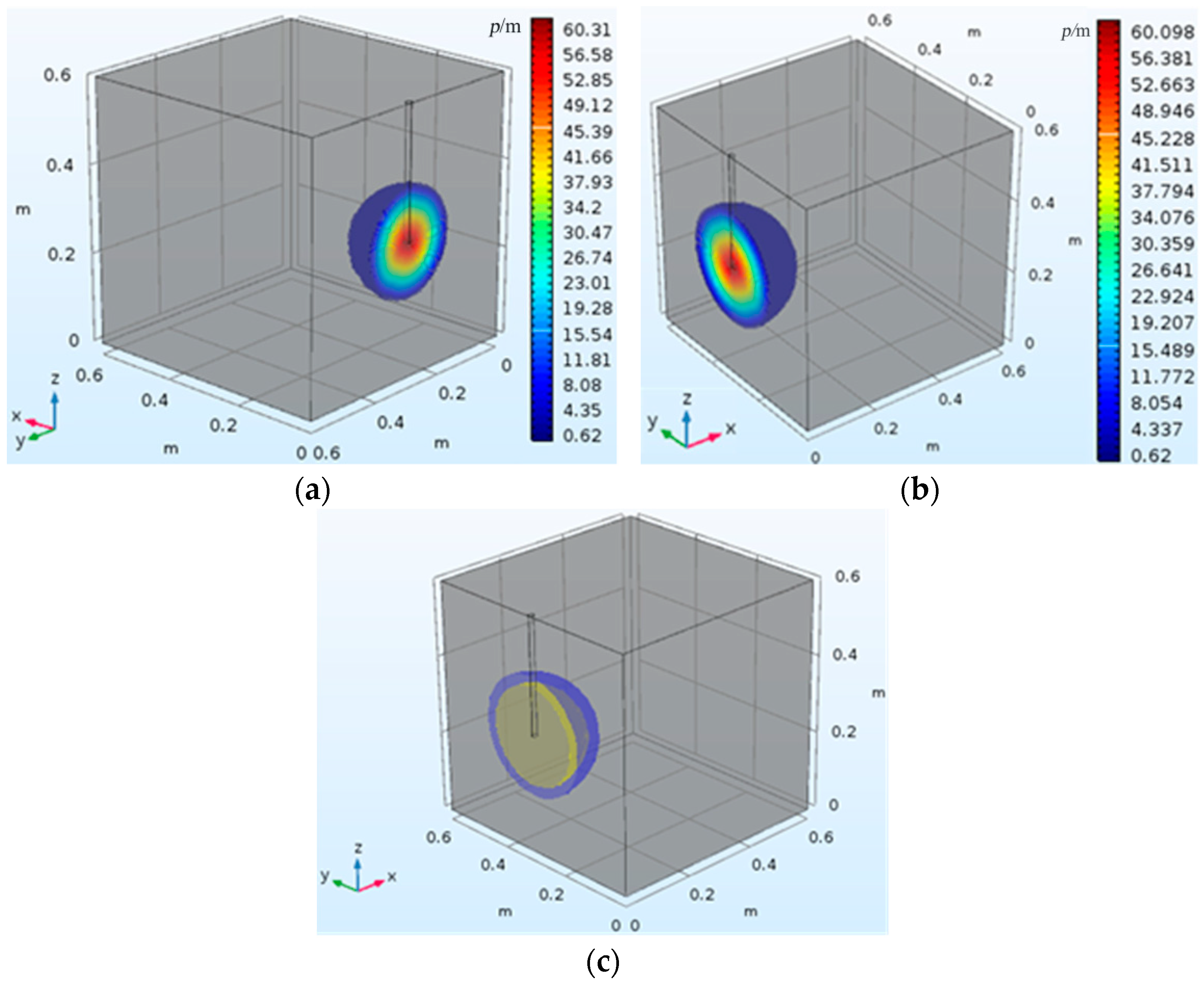
Relying on the multi-physics field coupling software COMSOL Multiphysics platform and Darcy’s law, three-dimensional numerical calculation programs for the mechanism were obtained by using secondary development programming technology. Accordingly, numerical simulations of the penetration grouting process of the power-law fluid with different time-dependent behaviors for reinforcing loose gravel soil were carried out. The numerical simulation results show that the penetration diffusion patterns of power-law cement grouts in gravel soil with and without considering the time-dependent behavior of fluid are hemispherical, which is also consistent with the penetration diffusion theoretical model of this mechanism. In addition, the range of the spatial penetration diffusion considering the time-dependent behavior of grouts is smaller than that without considering the time-dependent behavior.
(4)
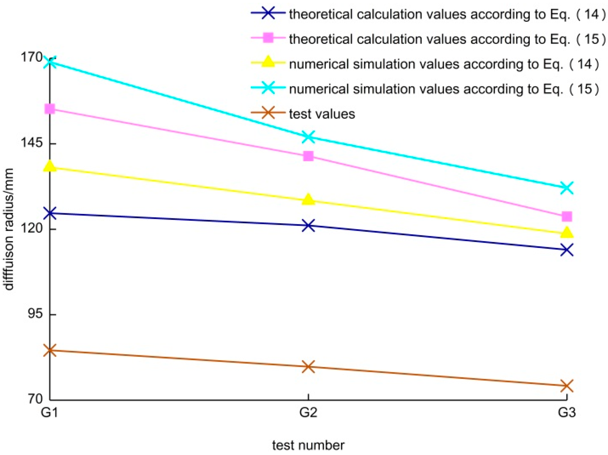
The mechanism was validated by comparing the results from theoretical analyses, indoor experiments, and numerical simulations. Research results show that the three-dimensional numerical calculation programs can successfully simulate the penetration diffusion patterns of a time-dependent power-law fluid in loose gravel soil. The theoretical calculation values and numerical simulation values of the diffusion radius obtained from the mechanism are closer to the indoor experimental values than those obtained from penetration grouting diffusion theory.
In summation, the mechanism can better reflect the penetration grouting diffusion laws of the power-law fluid in loose gravel soil than the penetration grouting diffusion theory, providing theoretical support and guidance for practical grouting construction.

Author Contributions

Conceptualization, T.G. and Z.Y.; Methodology, Z.Z. and Z.Y.; Formal analysis, T.G., Z.Z. and Z.Y.; Writing—original draft: T.G. and Z.Y.; Writing—review and editing, Z.Z., Z.Y. and Y.Z.; Software: Z.Y.; Funding acquisition, T.G. and Z.Y.; Supervision, T.G., Z.Y., Y.Z. and Y.Y.; Validation, T.G., Z.Z. and Y.Y.; Visualization: Z.Z. and Z.Y.; and Resources: Y.G. (Yanhui Guo), Y.M., R.W., B.Z., Y.F., D.Y., J.S., H.L., J.Z., Y.G. (Yongfa Guo) and H.W. All authors have read and agreed to the published version of the manuscript.

Funding

This research was funded by National Natural Science Foundation of China (Grant No. 41861134008), Muhammad Asif Khan academician workstation of Yunnan Province (Grant No. 202105AF150076), Key R&D Program of Yunnan Province(Grant No. 202003AC100002), General Program of basic research plan of Yunnan Province (Grant No. 202001AT070043) and Science and Research Program of Yunnan Education Department (Grant No. 2018JS029).

Data Availability Statement

Data are contained within the article.

Acknowledgments

The authors acknowledge the financial supports of National Natural Science Foundation of China (Grant No. 41861134008), Muhammad Asif Khan academician workstation of Yunnan Province (Grant No. 202105AF150076), Key R&D Program of Yunnan Province(Grant No. 202003AC100002), General Program of basic research plan of Yunnan Province (Grant No. 202001AT070043) and Science and Research Program of Yunnan Education Department (Grant No. 2018JS029).

Conflicts of Interest

The authors declare that they have no known competing financial interests or personal relationships that could have appeared to influence the work reported in this paper.

References

  1. Rahmani, H.; Naeini, S.A. Influence of non-plastic fine on static iquefaction and undrained monotonic behavior of sandy gravel. Eng. Geol. 2020, 275, 105729. [Google Scholar] [CrossRef]
  2. Zhao, B.; Liu, D.; Jiang, B. Soil Conditioning of Waterless SandPebble Stratum in EPB Tunnel Construction. Geotech. Geol. Eng. 2018, 36, 2495–2504. [Google Scholar] [CrossRef]
  3. Achour, Y.; Boumezbeur, A.; Hadji, R.; Chouabbi, A.; Cavaleiro, V.; Bendaoud, E.A. Landslide susceptibility mapping using analytic hierarchy process and information value methods along a highway road section in Constantine, Algeria. Arab. J. Geosci. 2017, 10, 194. [Google Scholar] [CrossRef]
  4. Cui, P.; Zhu, Y.-Y.; Han, Y.-S.; Chen, X.-Q.; Zhuang, J.-Q. The 12 May Wenchuan earthquake-induced landslide lakes: Distribution and preliminary risk evaluation. Landslides 2009, 6, 209–223. [Google Scholar] [CrossRef]
  5. Macciotta, R.; Martin, C.D.; Morgenstern, N.R.; Cruden, D.M. Quantitative risk assessment of slope hazards along a section of railway in the Canadian Cordillera-a methodology considering the uncertainty in the results. Landslides 2016, 13, 115–127. [Google Scholar] [CrossRef]
  6. Lan Chau, N.; Pham Van, T.; Tuan-Nghia, D. Deep-seated rainfall-induced landslides on a new expressway: A case study in Vietnam. Landslides 2020, 17, 395–407. [Google Scholar] [CrossRef]
  7. Nie, L.; Li, Z.; Zhang, M.; Xu, L. Deformation characteristics and mechanism of the landslide in West Open-Pit Mine, Fushun, China. Arab. J. Geosci. 2015, 8, 4457–4468. [Google Scholar] [CrossRef]
  8. Ouyang, C.; Zhou, K.; Xu, Q.; Yin, J.; Peng, D.; Wang, D.; Li, W. Dynamic analysis and numerical modeling of the 2015 catastrophic landslide of the construction waste landfill at Guangming, Shenzhen, China. Landslides 2017, 14, 705–718. [Google Scholar] [CrossRef]
  9. Pankow, K.L.; Moore, J.R.; Hale, J.M.; Koper, K.D.; Mccarter, M.K. Massive landslide at Utah copper mine generates wealth of geophysical data. Gsa Today 2014, 24, 4–9. [Google Scholar] [CrossRef] [Green Version]
  10. Yang, Z.; Zhu, Y.; Qian, S.; Hou, K. Types and space distribution characteristics of debris flow disasters along China-Pakistan highway. Electron. J. Geotech. Eng. 2016, 21, 191–200. [Google Scholar]
  11. Li, X.; Liu, Z.; Yang, S. Similar physical modeling of roof stress and subsidence in room and pillar mining of a gently inclined medium-thick phosphate rock. Adv. Civ. Eng. 2021, 2021, 6686981. [Google Scholar] [CrossRef]
  12. Geng, J.; Li, Q.; Li, X.; Zhou, T.; Liu, Z.; Xie, Y. Research on the evolution characteristics of rock mass response from open-pit to underground mining. Adv. Mater. Sci. Eng. 2021, 2021, 3200906. [Google Scholar] [CrossRef]
  13. Shi, X.; Liu, K.; Yin, J. Effect of Initial Density, Particle Shape, and Confining Stress on the Critical State Behavior of Weathered Gap-Graded Granular Soils. J. Geotech Geoenviron. 2021, 147, 04020160. [Google Scholar] [CrossRef]
  14. Chen, N.; Gao, Y.; Yang, C.; Hu, G. Effect of clay content to the strength of gravel soil in the source region of debris flow. J. Mt. Sci-Engl. 2018, 15, 2320–2334. [Google Scholar] [CrossRef]
  15. Li, X.; Peng, K.; Peng, J.; Xu, H. Effect of cyclic wetting-drying treatment on strength and failure behavior of two quartz-rich sandstones under direct shear. Rock. Mech. Rock. Eng. 2021, 39, 1–11. [Google Scholar] [CrossRef]
  16. Li, X.; Peng, K.; Peng, J.; Hou, D. Effect of thermal damage on mechanical behavior of a fine-grained sandstone. Arab. J. Geosci. 2021, 14. [Google Scholar] [CrossRef]
  17. Do, J.; Heo, S.; Yoon, Y.W.; Chang, I. Evaluating the liquefaction potential of gravel soils with static experiments and steady state approaches. Ksce J. Civ. Eng. 2017, 21, 642–651. [Google Scholar] [CrossRef]
  18. Yang, P.; Peng, Z.; Tang, Y.; Peng, W.; He, Z. Penetration grouting reinforcement of sandy gravel. J. Cent. South Univ. Technol. 2008, 15, 280–284. [Google Scholar] [CrossRef]
  19. Yang, Z.; Qian, S.; Kepeng, H.; Liang, W.; Lu, Y. Technological parameters of reinforced coarse-grained soil by grouting technology. Electron. J. Geotech. Eng. 2015, 20, 13347–13356. [Google Scholar]
  20. Chun, B.S.; Lee, Y.J.; Chung, H.I. Effectiveness of Control Leakage after Application of Permeation Grouting to Earth Fill Dam. Ksce J. Civ. Eng. 2006, 10, 405–414. [Google Scholar] [CrossRef]
  21. Ding, L.; Wang, F.; Luo, H.; Yu, M.; Wu, X. Feedforward Analysis for Shield-Ground System. J. Comput. Civ. Eng. 2013, 27, 231–242. [Google Scholar] [CrossRef]
  22. El Mohtar, C.S.; Yoon, J.; Sangroya, R.; Jaffal, H. Transferring innovative research into practical wisdom: The case of permeation grouting. Innov. Infrastruct. Solut. 2017, 2, 37. [Google Scholar] [CrossRef]
  23. Jones, B.R.; Van Rooy, J.L.; Mouton, D.J. Verifying the ground treatment as proposed by the Secondary Permeability Index during dam foundation grouting. Bull. Eng. Geol. Env. 2019, 78, 1305–1326. [Google Scholar] [CrossRef]
  24. Park, D.; Oh, J. Permeation grouting for remediation of dam cores. Eng. Geol. 2018, 233, 63–75. [Google Scholar] [CrossRef]
  25. Rasouli, R.; Hayashi, K.; Zen, K. Controlled Permeation Grouting Method for Mitigation of Liquefaction. J. Geotech. Geoenviron. Eng. 2016, 142, 04016052. [Google Scholar] [CrossRef]
  26. Takano, S.; Hayashi, K.; Zen, K.; Rasouli, R. Controlled Curved Drilling Technique in the Permeation Grouting Method for Improvement Works of an Airport in Operation. Procedia Eng. 2016, 143, 539–547. [Google Scholar] [CrossRef] [Green Version]
  27. Li, X.; Yang, S.; Wang, Y.; Nie, W.; Liu, Z. Macro-micro response characteristics of surrounding rock and overlying strata towards the transition from open-pit to underground mining. Geofluids 2021, 2021. [Google Scholar] [CrossRef]
  28. Liu, Q.; Lei, G.; Peng, X.; Lu, C.; Wei, L. Rheological Characteristics of Cement Grout and its Effect on Mechanical Properties of a Rock Fracture. Rock Mech. Rock Eng. 2018, 51, 613–625. [Google Scholar] [CrossRef]
  29. Ruan, W. Research on diffusion of grouting and basic properties of grouts. Chin. J. Geotech. Eng. 2005, 1, 69–73. [Google Scholar]
  30. Yang, Z.; Hou, K.; Guo, T. Study on the Effects of Different Water-cement Ratios on the Flow Pattern Properties of Cement Grouts. Appl. Mech. Mater 2011, 71, 1264–1267. [Google Scholar] [CrossRef]
  31. Karol, R.H. Chemical Grouting and Soil Stabilization; Marcel Dekker: New York, NY, USA, 2003. [Google Scholar]
  32. Huang, F.; Lyu, J.; Gao, H.; Wang, G. Modified Maag’s Spherical Diffusion Model of Vacuum Penetration Grouting. Math. Probl. Eng. 2018, 2018. [Google Scholar] [CrossRef] [Green Version]
  33. Raffle, J.F.; Greenwood, D.A. Relation between the rheological characteristics of grouts and their capacity to permeate soil. In Proceedings of the 5th International Conderence on Soil Mechnics and Foundation Engineering, Paris, France, 12–22 June 1961; pp. 789–794. [Google Scholar]
  34. Li, S.; Zhao, W.; Huang, Y.; Lei, Y.; Yu, L. Study on the characteristics of grout permeation based on cylindrical diffusion. J. Coal Sci. Eng. 2013, 19, 57–62. [Google Scholar] [CrossRef]
  35. Yang, Z.; Qian, S.; Hou, K.; Liang, W.; Lu, Y. Recommended theoretical calculation formulas of diffusion parameters of newton fluid based on column-hemisphere penetration grouting. Electron. J. Geotech. Eng. 2015, 20, 13497–13504. [Google Scholar]
  36. Baker, C. Comments on Paper Rock Stabilization in Rock Mechanics; Springer: New York, NY, USA, 1974; pp. 45–78. [Google Scholar]
  37. Hassler, L.; Hakansson, U.; Stille, H. Computer-simulated flow of grouts in jointed rock. Tunn. Undergr. Space Technol 1992, 30, 461–473. [Google Scholar] [CrossRef]
  38. Funehag, J.; Fransson, A. Sealing narrow fractures with a Newtonian fluid: Model prediction for grouting verified by field study. Tunn. Undergr. Space Technol. 2006, 21, 492–498. [Google Scholar] [CrossRef]
  39. Amadei, B.; Illangasekare, T. A mathematical model for flow and solute transport in non-homogeneous rock fractures. Int. J. Rock Mech. Min. Sci. Geomech. Abstr. 1994, 31, 719–731. [Google Scholar] [CrossRef]
  40. Zhang, Q.; Zhang, L.; Liu, R.; Li, S.; Zhang, Q. Grouting mechanism of quick setting slurry in rock fissure with consideration of viscosity variation with space. Tunn. Undergr. Space Technol. 2017, 70, 262–273. [Google Scholar] [CrossRef]
  41. Ding, Y.; Yang, Z.-Q.; Yang, Y.; Zhu, Y.-Y.; Guo, Y.-F.; Zhang, J.; Chen, X. Study on Penetration Grouting Mechanism Based on Newton Fluid of Time-Dependent Behavior of Rheological Parameters. Shock Vib. 2020, 2020. [Google Scholar] [CrossRef]
  42. Yang, Z.; Ding, Y.; Yang, Y.; Zhu, Y.; Zhang, J.; Guo, Y.; Chen, X. Hydration-time-dependent rheological behaviors of Newtonian cement grouts with different water cement ratios. Trans. Chin. Soc. Agric. Eng. 2020, 36, 161–167. [Google Scholar]
  43. Liao, K.; Fan, J.; Huang, C. An artificial neural network for groutability prediction of permeation grouting with microfine cement grouts. Comput. Geotech. 2011, 38, 978–986. [Google Scholar] [CrossRef]
  44. Fan, J.; Liu, W.-a.; Liu, C.; Huang, C.; Tan, Y.; Guo, J. Evaluating Permeability and Efficiency of Substrates by Using Permeation Grouting Sand Column Test. Ksce J. Civ. Eng. 2018, 22, 2843–2855. [Google Scholar] [CrossRef]
  45. Tekin, E.; Akbas, S.O. Artificial neural networks approach for estimating the groutability of granular soils with cement-based grouts. Bull. Eng. Geol. Environ. 2011, 70, 153–161. [Google Scholar] [CrossRef]
  46. Saada, Z.; Canou, J.; Dormieux, L.; Dupla, J.-C. Evaluation of elementary filtration properties of a cement grout injected in a sand. Can. Geotech. J. 2006, 43, 1273–1289. [Google Scholar] [CrossRef]
  47. Kim, J.-S.; Lee, I.-M.; Jang, J.-H.; Choi, H. Groutability of cement-based grout with consideration of viscosity and filtration phenomenon. Int. J. Numer. Anal. Methods Geomech. 2009, 33, 1771–1797. [Google Scholar] [CrossRef]
  48. Bouchelaghem, F.; Vulliet, L.; Leroy, D.; Laloui, L.; Descoeudres, F. Real-scale miscible grout injection experiment and performance of advection-dispersion-filtration model. Int. J. Numer. Anal. Methods Geomech. 2001, 25, 1149–1173. [Google Scholar] [CrossRef]
  49. Eriksson, M.; Stille, H.; Andersson, J. Numerical calculations for prediction of grout spread with account for filtration and varying aperture. Tunn. Undergr. Space Technol. 2000, 15, 353–364. [Google Scholar] [CrossRef]
  50. Chupin, O.; Saiyouri, N.; Hicher, P.-Y. The effects of filtration on the injection of cement-based grouts in sand columns. Transp. Porous Media 2008, 72, 227–240. [Google Scholar] [CrossRef]
  51. Maghous, S.; Saada, Z.; Dormieux, L.; Canou, J.; Dupla, J.C. A model for in situ grouting with account for particle filtration. Comput. Geotech. 2007, 34, 164–174. [Google Scholar] [CrossRef]
  52. Yoon, J.; El Mohtar, C.S. A filtration model for evaluating maximum penetration distance of bentonite grout through granular soils. Comput. Geotech. 2015, 65, 291–301. [Google Scholar] [CrossRef]
  53. Uddin, M.K. Permeation grouting in sandy soils: Prediction of injection rate and injection shape. Geotech. Eng. 2007, 38, 1–7. [Google Scholar]
  54. Dayakar, P.; Raju, D.K.V.; Sankaran, B.S. Improvement of coarse grained soil by permeation grouting using cement based HPMC grout. Int. J. Emerg. Technol. Adv. Eng. 2014, 4, 17–22. [Google Scholar]
  55. Bolisetti, T. Experimental and Numerical Investigations Of Chemical Grouting In Heterogeneous Porous Media; University of Windsor: Windsor, Canada, 2005. [Google Scholar]
  56. Bolisetti, T.; Reitsma, S.; Balachandar, R. Experimental Investigations of Colloidal Silica Grouting in Porous Media. J. Geotech. Geoenviron. Eng. 2009, 135, 697–700. [Google Scholar] [CrossRef]
  57. Anagnostopoulos, C.A. Laboratory study of an injected granular soil with polymer grouts. Tunn. Undergr. Space Technol. 2005, 20, 525–533. [Google Scholar] [CrossRef]
  58. Ye, F.; Yang, T.; Mao, J.-h.; Qin, X.-z.; Zhao, R.-l. Half-spherical surface diffusion model of shield tunnel back-fill grouting based on infiltration effect. Tunn. Undergr. Space Technol. 2019, 83, 274–281. [Google Scholar] [CrossRef]
  59. Zhou, Z.; Du, X.; Chen, Z.; Zhao, Y. Grouting diffusion of chemical fluid flow in soil with fractal characteristics. J. Cent. South Univ. 2017, 24, 1190–1196. [Google Scholar] [CrossRef]
  60. Lombardi, G. The role of the cohesion on cement grouting of rock. In Proceedings of the 15th International Congress on Large Dams, International Commission on Large Dams, Lausanne, Switzerland, 24–28 June 1985; pp. 235–261. [Google Scholar]
  61. Amadei, B.; Savage, W.Z. An analytical solution for transient flow of Bingham viscoplastic materials in rock fractures. Int. J. Rock Mech. Min. Sci. Geomech. Abstr. 2001, 38, 285–296. [Google Scholar] [CrossRef]
  62. Lee, J.S.; Bang, C.S.; Mok, Y.J.; Joh, S.H. Numerical and experimental analysis of penetration grouting in jointed rock masses. Int. J. Rock Mech. Min. Sci. 2000, 37, 1027–1037. [Google Scholar] [CrossRef]
  63. Liu, Q.; Sun, L.; Tang, X. Investigate the influence of the in-situ stress conditions on the grout penetration process in fractured rocks using the combined finite-discrete element method. Eng. Anal. Bound. Elem. 2019, 106, 86–101. [Google Scholar] [CrossRef]
  64. Sun, L.; Grasselli, G.; Liu, Q.; Tang, X. Coupled hydro-mechanical analysis for grout penetration in fractured rocks using the finite-discrete element method. Int. J. Rock Mech. Min. Sci. 2019, 124. [Google Scholar] [CrossRef]
  65. Mohammed, M.H.; Pusch, R.; Knutsson, S. Study of cement-grout penetration into fractures under static and oscillatory conditions. Tunn. Undergr. Space Technol. 2015, 45, 10–19. [Google Scholar] [CrossRef]
  66. Wallner, M. Propagation of sedimentation stable cement pastes in jointed rock: Wallner, M Publ Inst Found Engng, Soil Mech, Rock Mech, Waterways Constr, Aachen, V2, 1976, P49–165. Int. J. Rock Mech. Min. Sci. Geomech. Abstr. 1977, 14, 14. [Google Scholar] [CrossRef]
  67. Gustafson, G.; Claesson, J.; Fransson, A. Steering Parameters for Rock Grouting. J. Appl. Math. 2013, 2013. [Google Scholar] [CrossRef]
  68. Pedrotti, M.; Wong, C.; El Mountassir, G.; Lunn, R.J. An analytical model for the control of silica grout penetration in natural groundwater systems. Tunn. Undergr. Space Technol. 2017, 70, 105–113. [Google Scholar] [CrossRef] [Green Version]
  69. Sui, W.; Liu, J.; Hu, W.; Qi, J.; Zhan, K. Experimental investigation on sealing efficiency of chemical grouting in rock fracture with flowing water. Tunn. Undergr. Space Technol. 2015, 50, 239–249. [Google Scholar] [CrossRef]
  70. Li, S.; Liu, R.; Zhang, Q.; Sun, Z.; Zhang, X.; Zhu, M. Research on C-S slurry diffusionmechanism with time-dependent behavior of viscosity. Chin. J. Rock Mech. Eng. 2013, 32, 2415–2421. [Google Scholar]
  71. Yang, Z.; Hou, K.; Guo, T. study of colunm-hemispherical penetration grouting mechanism based on Bingham fluid of time-dependent behavior of viscosity. Rock Soil Mech. 2011, 32, 2698–2703. (In Chinese) [Google Scholar] [CrossRef]
  72. Yang, Z.; Hou, K.; Guo, T.; Ma, Q. Study on penetration grouting mechanism based on bingham fluid of time-dependent behavior. J. Sichuan Univ. (Eng. Sci. Ed.) 2011, 43, 67–72. (In Chinese) [Google Scholar] [CrossRef]
  73. Yang, Z.; Niu, X.; Hou, K.; Guo, Y.; Zou, Z.; Chen, F.; Kang, Y. Study on diffusion parameters of Bingham fluid based on column-hemispherical penetration grouting. Adv. Eng. Sci. 2015, 47, 47–53. (In Chinese) [Google Scholar] [CrossRef]
  74. Yang, E.; Li, H.; Gao, H. Calculation method of power law fluid equivalent permeability considering capillary shape. Chin. Q. J. Math. 2015, 30, 420–428. [Google Scholar]
  75. Zhang, B.; Yu, B.; Wang, H.; Yun, M. A fractal analysis of permeability for power-law fluids in porous media. Fractals-Complex Geom. Patterns Scaling Nat. Soc. 2006, 14, 171–177. [Google Scholar] [CrossRef]
  76. Yang, Z.; Niu, X.; Hou, K.; Guo, Y.; Liang, W.; Zhou, Z. Column penetration grouting mechanism researches based on Power-law fluid. J. Harbin Inst. Technol. 2016, 48, 178–183. [Google Scholar]
  77. Yang, Z.; Niu, X.; Hou, K.; Zhou, Z.; Liang, W.; Guo, Y.; Lu, Y.; Yang, B.; Cheng, Y. Columnar diffusion of cement grout with the time dependent rheological parameters. Chin. J. Rock Mech. Eng. 2015, 34, 1415–1425. (In Chinese) [Google Scholar] [CrossRef]
  78. Fu, Y.; Wang, X.; Zhang, S.; Yang, Y. Modelling of Permeation Grouting considering Grout Self-Gravity Effect: Theoretical and Experimental Study. Adv. Mater. Sci. Eng. 2019, 2019. [Google Scholar] [CrossRef] [Green Version]
  79. Zhang, W. The grouting diffusion model of power-law fluid in single fracture. Appl. Mech. Mater. 2014, 477–478, 524–530. [Google Scholar] [CrossRef]
  80. Yang, Z.; Ding, Y.; Mi, Y.; Zhu, Y.; Yang, Y.; Guo, Y.; Zhang, B.; Li, S.; Su, J.; Chen, J.; et al. Comprehensive Effect of the Time and Water-Cement Ratio on the Rheological Properties of Power-Law Cement Grouts. Geofluids 2021, 2021, 6636708. [Google Scholar] [CrossRef]
  81. Yang, Z.; Lu, J.; Wang, Y.; Zhang, Z.; Yang, Y. Zhu, Y. Zhang, J. Guo, Y.; Chen, X. Column penetration mechanism for power-law fluids considering tortuosity effect of porous media. Chin. J. Rock Mech. Eng. 2021, 40, 410–418. (In Chinese) [Google Scholar] [CrossRef]
  82. Yang, Z.; Hou, K.; Guo, T. Research on Time-varying Behavior of Cement Grouts of Different Water-cement Ratios. Appl. Mech. Mater 2011, 71–78, 4398–4401. [Google Scholar] [CrossRef]
  83. Yang, Z.; Qian, S.; Hou, K. Time-dependent behavior characteristics of Power-law cement grouts applied in geotechnical engineering. Electron. J. Geotech. Eng. 2015, 20, 1017–1024. [Google Scholar]
  84. Zenit, R.; Koch, D.L.; Sangani, A.S. Measurements of the average properties of a suspension of bubbles rising in a vertical channel. J. Fluid Mech. 2001, 429, 307–342. [Google Scholar] [CrossRef] [Green Version]
Figure 1. Penetration diffusion theoretical model of power-law fluid in injected medium.
Minerals 11 01391 g001
Figure 2. Grouting experimental device ((a) Schematic diagram, (b) Physical diagram). ①—Pressure supply equipment, ②—grouts storage box, ③—experimental box, ④—nitrogen pressure reducer and grouting control switch, ⑤—time-dependent power-law fluid, ⑥—electronic scale, ⑦—grouting pipe, ⑧—gravel (sand) with uniform particle size.
Minerals 11 01391 g002
Figure 3. Time-dependent characteristics of three kinds of cement grouts. (a) Time-dependent characteristics of consistency coefficient, (b) Time-dependent characteristics of rheological index.
Minerals 11 01391 g003
Figure 4. Pictures of grouting experimental process. (a) Penetration diffusion pattern, (b) Grouted stone body.
Minerals 11 01391 g004
Figure 5. Distribution of porosity and permeability coefficient of gravel soil simulated by the model ((a) Porosity distribution, dimensionless, (b) Permeability coefficient distribution K/cm/s).
Minerals 11 01391 g005
Figure 6. Numerical simulation results of penetration diffusion patterns of power-law cement grouts in gravel soil. ((a) Simulation results considering time-dependent behavior of grouts, (b) Simulation results without considering time-dependent behavior of grouts, (c) Simulation results considering both conditions; yellow and blue are, respectively, penetration diffusion patterns of considering and not considering time-dependent behavior of grouts, dimensionless).
Minerals 11 01391 g006
Figure 7. Comparison between experimental values and numerical simulation values of the diffusion radius. ((ac)—Comparison results of G1, G2, and G3. In the figure, red is experimental value, and other colors are shown in Figure 6c, dimensionless).
Minerals 11 01391 g007
Figure 8. Comparison of experimental values, theoretical calculation values, and numerical simulation values of the diffusion radius.
Minerals 11 01391 g008
Table 1. Rheological equations and time-dependent equations of consistency coefficient of three kinds of power-law cement grouts.
Water–Cement RatioRheological EquationTime-Dependent Equation of Consistency Coefficient
0.5 τ = 10.4426 γ 0.1406 C ( t ) = 10.4507 e 0.0011 t
0.6 τ = 4.6156 γ 0.2692 C ( t ) = 4.4195 e 0.0010 t
0.7 τ = 1.9321 γ 0.4537 C ( t ) = 1.8656 e 0.0009 t
Note: The unit of time t is seconds.
Table 2. Properties of three kinds of injected gravel (sand) materials.
Particle Grading of Injected Gravel SoilSpecific Gravity
ds
Water Content
ω/%
Density
ρ/g/cm3
Permeability Coefficient K/cm/sPorosity ϕ/
%
Material Mark
1–3mm2.633.241.630.6539.93material 1
3–5mm2.652.791.502.1145.05material 2
5–10 mm2.722.181.378.9450.74material 3
Table 3. Design parameters of grouting simulation experiments.
Experimental NumberWater–Cement Ratio of Power-Law Cement GroutsInjected MediaGrouting Pressure/mGrouting Time/s
G10.5M361.22240
G20.6M245.92210
G30.7M130.61180
Table 4. Movement parameters of power-law cement grouts in grouting pipe within the first second of experiments.
Experimental NumberFlow Rate of Cement Grouts
Q 1 / l / s
Flow
Velocity of Cement Grouts v 1 / m / s
Density of Cement Grouts ρ /Kg/m3Stability Coefficient
Z 1
G10.351.981840786.32
G20.412.321750732.85
G30.543.061670675.43
Table 5. Measured three-dimensional diffusion dimensions of the x-axis, y-axis, and z-axis of grouted stone body.
Experimental Numberx-Axis/mmy-Axis/mmz-Axis/mmDifference between Maximum and Minimum Diffusion Dimension
G182.984.386.64.27%
G278.479.981.23.45%
G372.674.275.94.35%
Table 6. Experimental values, theoretical calculation values, and numerical simulation values of the diffusion radius.
Experimental Values, Theoretical Calculation Values, and Numerical Simulation Values of Diffusion Radius Experimental NumberTheoretical Calculation Values/mmNumerical Simulation Values/mmTest Value-Equivalent Diffusion Radius/mm
Calculation Based on Equation (14)Calculation Based on Equation (15)Simulation Based on Equation (14)Simulation Based on Equation (15)
G1124.7155.2138.1168.984.6
G2121.1141.4128.4147.079.8
G3114.0123.7118.7132.174.2
Publisher’s Note: MDPI stays neutral with regard to jurisdictional claims in published maps and institutional affiliations.

