
Safety Analysis of Synergetic Operation of Backfilling the Open Pit Using Tailings and Excavating the Ore Deposit Underground

Abstract
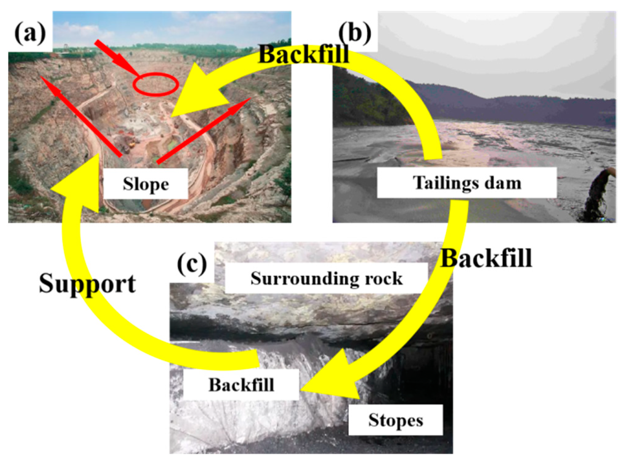
:1. Introduction
2. Methods and Proposals
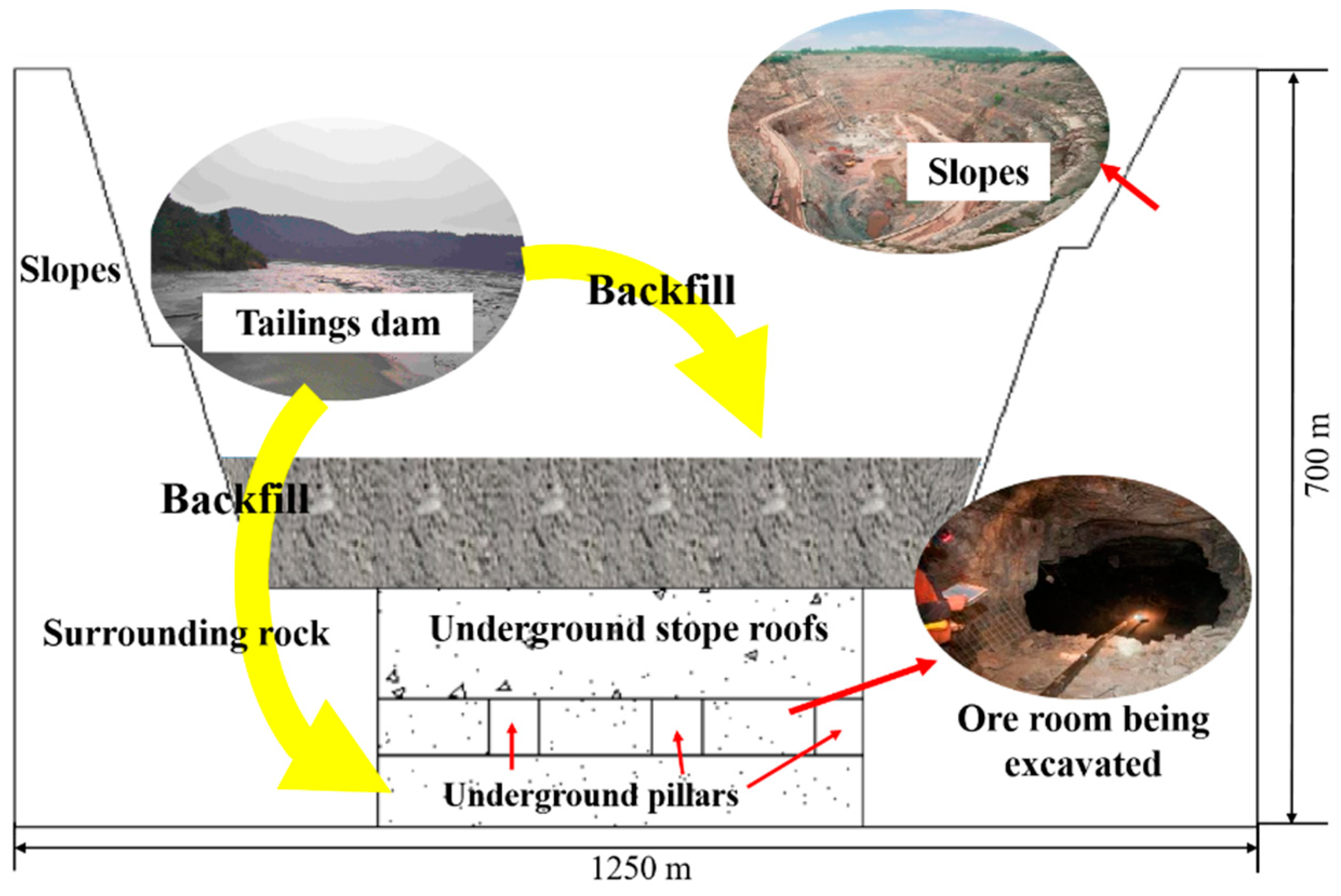
2.1. Study Site
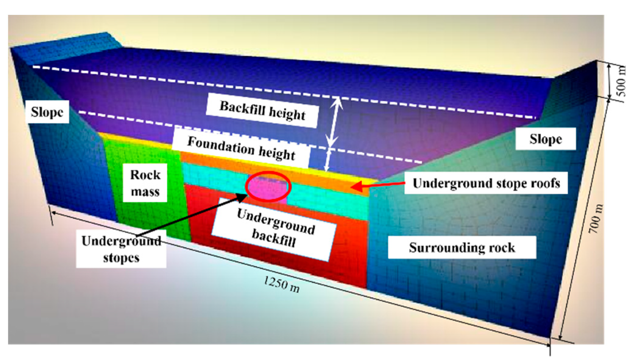
2.2. Numerical Simulation Tests
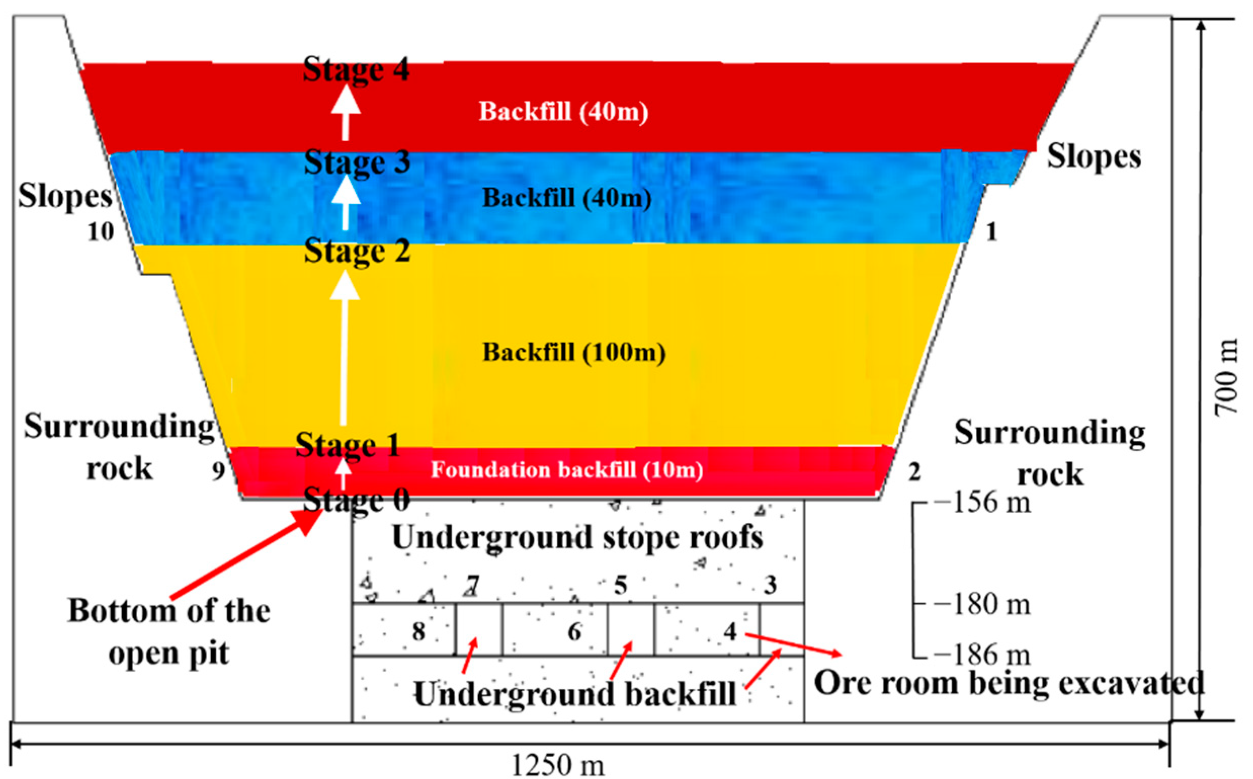
2.2.1. Modeling
2.2.2. Parameters
2.2.3. Simulation Schemes
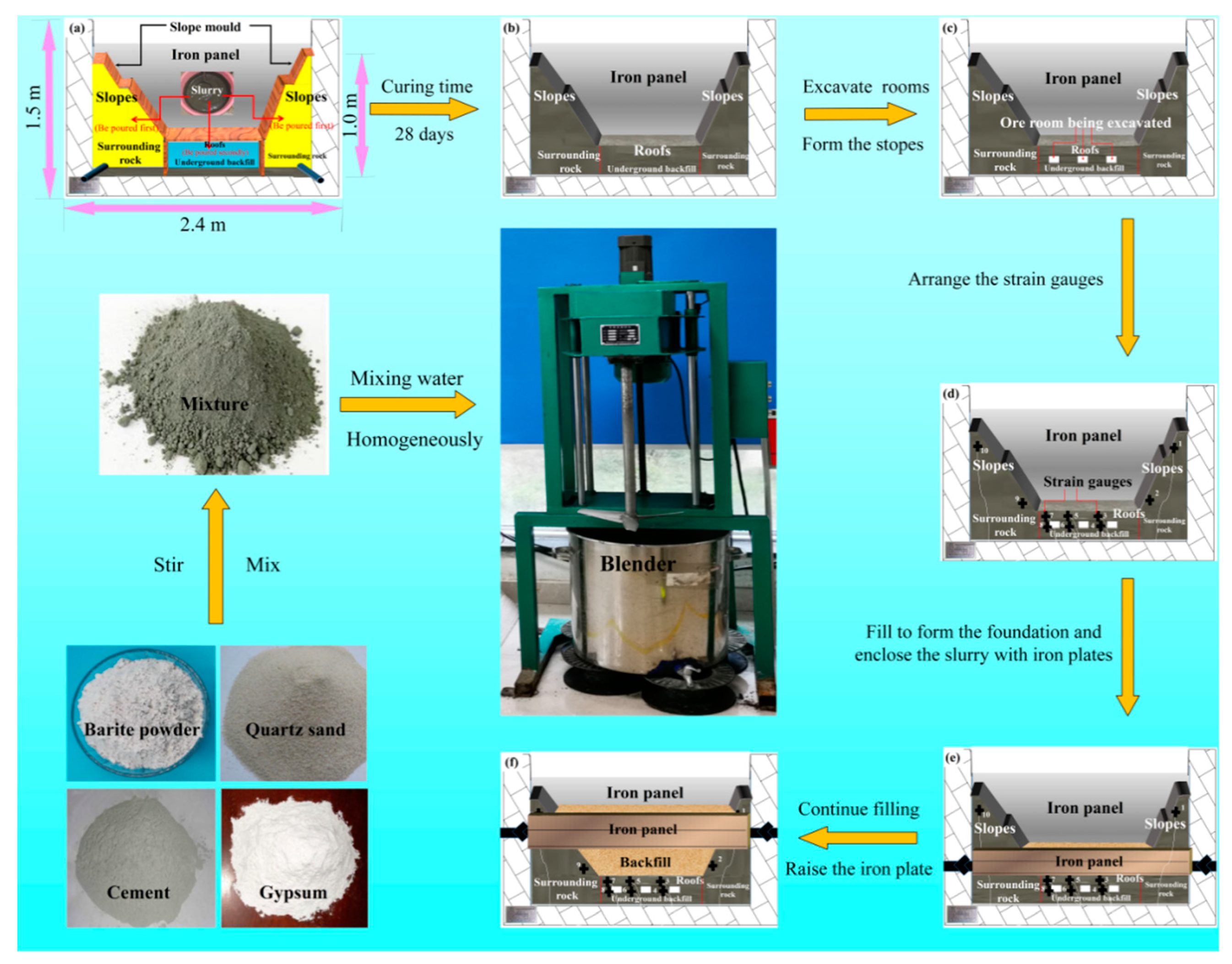
2.3. Physical Model
2.3.1. Similar Materials
2.3.2. Parameters
2.3.3. Modeling Process
Modeling the Open Pit
OPB
3. Results and Discussion
3.1. The Influence of OPB on the Stope Roofs
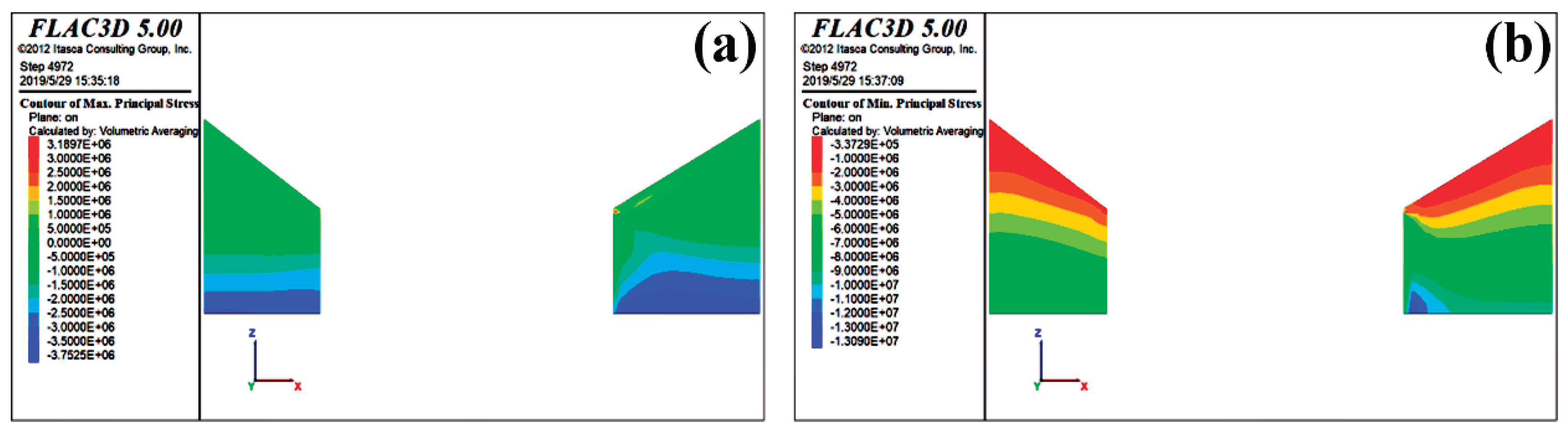
3.1.1. The Stress Change
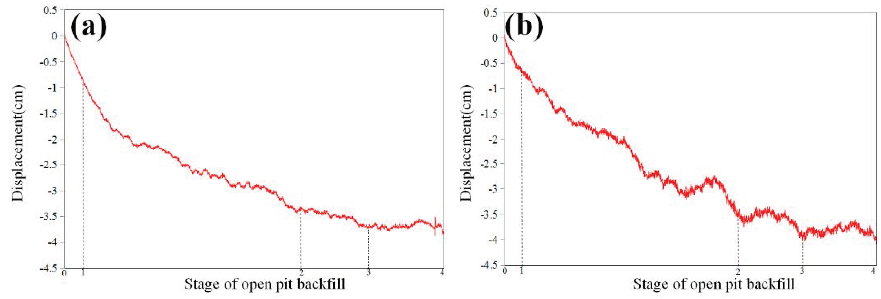
3.1.2. The Displacement Change
3.1.3. Displacement Change in the Similar Model
3.2. The Influence of OPB on the Underground Backfill Pillars
3.2.1. The Stress Change
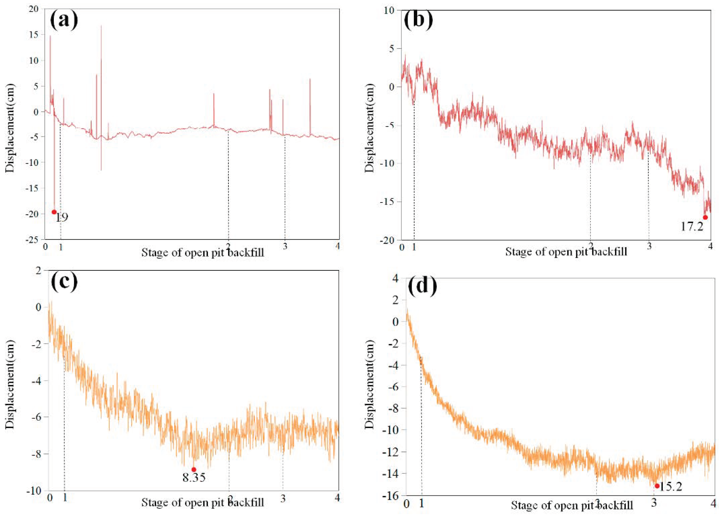
3.2.2. The displacement Change
3.2.3. Displacement Change in Similar Model
3.3. The Influence of OPB on the Open-Pit Slopes
3.3.1. The Stress Change
3.3.2. The Displacement Change
3.3.3. Displacement Change in the Similar Model
4. Conclusions
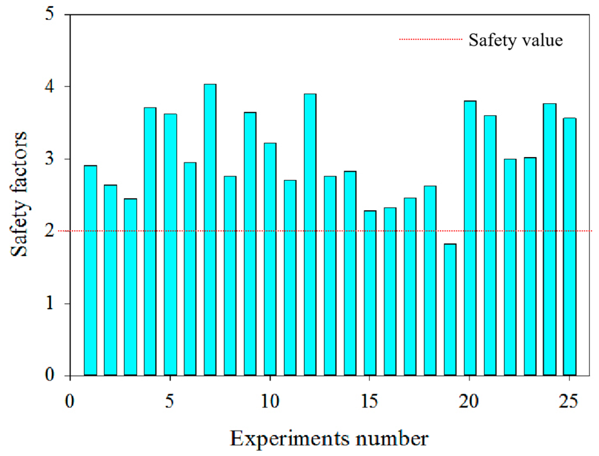
- (1)
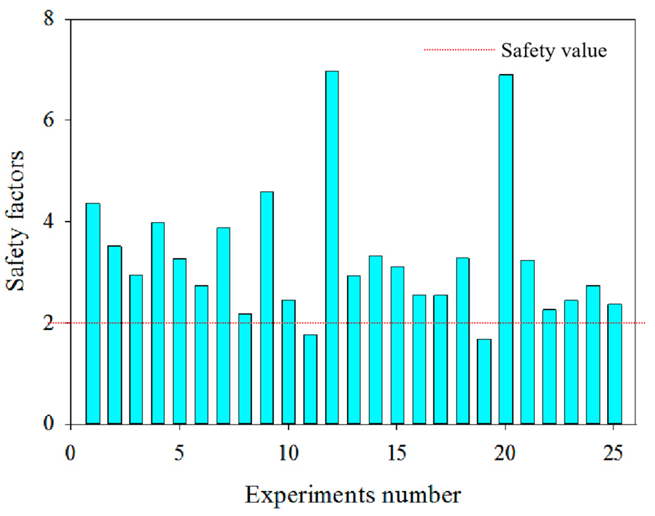
- Comprehensive analysis is obtained through ANOVA. Among the factors affecting the roofs and underground backfill pillars, the backfill height plays a significant role in roofs and underground backfill pillars. Moreover, the obtained safety factors meet the requirements. In other words, the safety of the roofs and underground backfill pillars during OPB is guaranteed. It should be indicated that the foundation strength, foundation height, backfill strength, and backfill height are 4 MPa, 10 m, 1.5 MPa, and 120 m, respectively.
- (2)
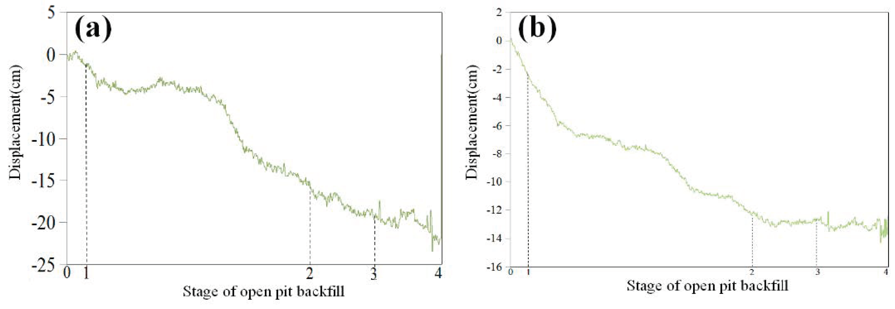
- The displacement gradually stabilizes when the backfill height is greater than 150 m. Moreover, no cracks or other damage appears, which verifies the reliability and accuracy of obtained numerical simulation results attained. In other words, the safety of the main regions, including the roofs, underground backfill pillars, and the slopes can be guaranteed during OPB.
Supplementary Materials
Author Contributions
Funding
Acknowledgments
Conflicts of Interest
References
- King, B.; Goycoolea, M.; Newman, A. Optimizing the open pit-to-underground mining transition. Eur. J. Oper. Res. 2017, 257, 297–309. [Google Scholar] [CrossRef]
- Dos Santos, T.B.; Lana, M.S.; Pereira, T.M.; Canbulat, I. Quantitative hazard assessment system (Has-Q) for open pit mine slopes. Int. J. Min. Sci. Technol. 2019, 29, 419–427. [Google Scholar] [CrossRef]
- Qi, C.; Fourie, A. Cemented paste backfill for mineral tailings management: Review and future perspectives. Miner. Eng. 2019, 144, 106025. [Google Scholar] [CrossRef]
- Wang, Q.; Li, J.; Zhu, X.; Yao, G.; Wu, P.; Wang, Z.; Lyu, X.; Hu, S.; Qiu, J.; Chen, P.; et al. Approach to the management of gold ore tailings via its application in cement production. J. Clean. Prod. 2020, 269, 122303. [Google Scholar] [CrossRef]
- Sun, W.; Wang, H.; Hou, K. Control of waste rock-tailings paste backfill for active mining subsidence areas. J. Clean. Prod. 2018, 171, 567–579. [Google Scholar] [CrossRef]
- Rimélé, M.A.; Dimitrakopoulos, R.; Gamache, M. A stochastic optimization method with in-pit waste and tailings disposal for open pit life-of-mine production planning. Resour. Policy 2018, 57, 112–121. [Google Scholar] [CrossRef]
- Dong, K.; Xie, F.; Wang, W.; Chang, Y.; Lu, D.; Gu, X.; Chen, C. The detoxification and utilization of cyanide tailings: A critical review. J. Clean. Prod. 2021, 302, 126946. [Google Scholar] [CrossRef]
- Chakilam, S.; Cui, L. Effect of polypropylene fiber content and fiber length on the saturated hydraulic conductivity of hydrating cemented paste backfill. Constr. Build. Mater. 2020, 262, 120854. [Google Scholar] [CrossRef]
- Qi, C.; Fourie, A.; Chen, Q.; Zhang, Q. A strength prediction model using artificial intelligence for recycling waste tailings as cemented paste backfill. J. Clean. Prod. 2018, 183, 566–578. [Google Scholar] [CrossRef]
- Benzaazoua, M.; Bussière, B.; Demers, I.; Aubertin, M.; Fried, É.; Blier, A. Integrated mine tailings management by combining environmental desulphurization and cemented paste backfill: Application to mine Doyon, Quebec, Canada. Min. Eng. 2008, 21, 330–340. [Google Scholar] [CrossRef]
- Bastola, S.; Cai, M.; Damjanac, B. Slope stability assessment of an open pit using lattice-spring-based synthetic rock mass (LS-SRM) modeling approach. J. Rock Mech. Geotech. Eng. 2020, 12. [Google Scholar] [CrossRef]
- Paul, S. Finite Element Analysis in Fused Deposition Modeling Research: A Literature Review. Measurement 2021, 178, 109320. [Google Scholar] [CrossRef]
- Tu, H.; Zhou, H.; Lu, J.; Gao, Y.; Shi, L. Elastoplastic coupling analysis of high-strength concrete based on tests and the Mohr-Coulomb criterion. Constr. Build. Mater. 2020, 255, 119375. [Google Scholar] [CrossRef]
- Zhang, J.; Wang, Z.; Song, Z. Numerical study on movement of dynamic strata in combined open-pit and under-ground mining based on similar material simulation experiment. Arab. J. Geosci. 2020, 13, 785. [Google Scholar] [CrossRef]
- Wang, J.; Ren, L.; Xie, L.; Xie, H.; Ai, T. Maximum mean principal stress criterion for three-dimensional brittle fracture. Int. J. Solids Struct. 2016, 102, 142–154. [Google Scholar] [CrossRef]
- Liu, B.; Zhou, J.; Wen, X.; Guo, J.; Deng, Z.; Hu, X. Mechanical performance and failure criterion of coral concrete under combined compression-shear stresses. Constr. Build. Mater. 2021, 288, 123050. [Google Scholar] [CrossRef]
- Ma, D.; Zhang, J.; Duan, H.; Huang, Y.; Li, M.; Sun, Q.; Zhou, N. Reutilization of gangue wastes in underground backfilling mining: Overburden aquifer protection. Chemosphere 2021, 264, 128400. [Google Scholar] [CrossRef]
- Khaboushan, A.S.; Osanloo, M.; Esfahanipour, A. Optimization of open pit to underground transition depth: An idea for reducing waste rock contamination while maximizing economic benefits. J. Clean. Prod. 2020, 277, 123530. [Google Scholar] [CrossRef]
- Tian, Q.; Zhang, J.; Zhang, Y. Similar simulation experiment of expressway tunnel in karst area. Constr. Build. Mater. 2018, 176, 1–13. [Google Scholar] [CrossRef]
- Tao, Z.; Shu, Y.; Yang, X.; Peng, Y.; Chen, Q.; Zhang, H. Physical model test study on shear strength characteristics of slope sliding surface in Nanfen open-pit mine. Int. J. Min. Sci. Technol. 2020, 30, 421–429. [Google Scholar] [CrossRef]
- Li, Y.; She, L.; Wen, L.; Zhang, Q. Sensitivity analysis of drilling parameters in rock rotary drilling process based on orthogonal test method. Eng. Geol. 2020, 270, 105576. [Google Scholar] [CrossRef]
- Morris, S.; Jackson, I. Implications of the similarity principle relating creep and attenuation in finely grained solids. Mater. Sci. Eng. A 2009, 521, 124–127. [Google Scholar] [CrossRef]
- Han, C.; Zhang, J. Study on well hard shut-in experiment based on similarity principle and erosion of ram rubber. Eng. Fail. Anal. 2013, 32, 202–208. [Google Scholar] [CrossRef]
- Ning, J.-H.; Zhou, Y.-D.; Fang, K.-T. Discrepancy for uniform design of experiments with mixtures. J. Stat. Plan. Inference 2011, 141, 1487–1496. [Google Scholar] [CrossRef]
- Feng, Y.; Yang, Q.; Chen, Q.; Kero, J.; Andersson, A.; Ahmed, H.; Engström, F.; Samuelsson, C. Characterization and evaluation of the pozzolanic activity of granulated copper slag modified with CaO. J. Clean. Prod. 2019, 232, 1112–1120. [Google Scholar] [CrossRef]
- Cardoso, V.H.; Caldas, P.; Giraldi, M.T.R.; Frazão, O.; de Carvalho, C.J.R.; Costa, J.C.; Santos, J.L. Experimental investigation of a strain gauge sensor based on Fiber Bragg Grating for diameter measurement. Opt. Fiber Technol. 2021, 61, 102428. [Google Scholar] [CrossRef]
- Naik, A.B.; Reddy, A.C. Optimization of tensile strength in TIG welding using the Taguchi method and analysis of variance (ANOVA). Therm. Sci. Eng. Prog. 2018, 8, 327–339. [Google Scholar] [CrossRef]
- Sei, T.; Shibata, H.; Takemura, A.; Ohara, K.; Takayama, N. Properties and applications of Fisher distribution on the rotation group. J. Multivar. Anal. 2013, 116, 440–455. [Google Scholar] [CrossRef]
- Huang, G.; Kulatilake, P.H.; Shreedharan, S.; Cai, S.; Song, H. 3-D discontinuum numerical modeling of subsidence incorporating ore extraction and backfilling operations in an underground iron mine in China. Int. J. Min. Sci. Technol. 2017, 27, 191–201. [Google Scholar] [CrossRef]
- Zingano, A.; Weiss, A. Subsidence over room and pillar retreat mining in a low coal seam. Int. J. Min. Sci. Technol. 2019, 29, 51–57. [Google Scholar] [CrossRef]
- Hai, P.; Jian, Z. Research on protecting the safety of buildings by using backfill mining with solid. Procedia Environ. Sci. 2012, 12, 191–198. [Google Scholar] [CrossRef] [Green Version]
- Lu, Y.; Li, M.; Wang, D.; Shi, X.; Li, H.; Zhu, Y.; Ye, Q.; Lu, J. Discharge and ignition characteristics from indentation fracture of coal mine roof. Fuel 2021, 291, 120208. [Google Scholar] [CrossRef]
- Asem, P.; Gardoni, P. Bayesian estimation of the normal and shear stiffness for rock sockets in weak sedimentary rocks. Int. J. Rock Mech. Min. Sci. 2019, 124, 104129. [Google Scholar] [CrossRef]
- Su, Z.; Shao, L. A three-dimensional slope stability analysis method based on finite element method stress analysis. Eng. Geol. 2021, 280, 105910. [Google Scholar] [CrossRef]
- Kinakin, D.; Stead, D. Analysis of the distributions of stress in natural ridge forms: Implications for the deformation mechanisms of rock slopes and the formation of sackung. Geomorphology 2005, 65, 85–100. [Google Scholar] [CrossRef]
- Wu, Z.; Chen, C.; Lu, X.; Pei, L.; Zhang, L. Discussion on the allowable safety factor of slope stability for high rockfill dams in China. Eng. Geol. 2020, 272, 105666. [Google Scholar] [CrossRef]
- Zheng, J.; Li, L. Experimental study of the “short-term” pressures of uncemented paste backfill with different solid contents for barricade design. J. Clean. Prod. 2020, 275, 123068. [Google Scholar] [CrossRef]
- Zhang, Q.; Li, Y.; Chen, Q.; Liu, Y.; Feng, Y.; Wang, D. Effects of temperatures and pH values on rheological properties of cemented paste backfill. J. Cent. South Univ. 2021, 28, 1707–1723. Available online: https://kns.cnki.net/kcms/detail/43.1516.tb.20210318.1429.002.html (accessed on 27 July 2021). [CrossRef]
- Xu, W.-B.; Liu, B.; Wu, W.-L. Strength and deformation behaviors of cemented tailings backfill under triaxial compression. J. Central South Univ. 2020, 27, 3531–3543. [Google Scholar] [CrossRef]
- Guo, Y.-X.; Ran, H.-Y.; Feng, G.-R.; Du, X.-J.; Qi, T.-Y.; Wang, Z.-H. Effects of curing under step-by-step load on mechanical and deformation properties of cemented gangue backfill column. J. Central South Univ. 2020, 27, 3417–3435. [Google Scholar] [CrossRef]
- Chen, Q.; Sun, S.; Liu, Y.; Qi, C.; Zhou, H.; Zhang, Q. Experimental and numerical study on immobilization and leaching characteristics of fluoride from phos-phogypsum based cemented paste backfill. Int. J. Min. Metall. Mater. 2021. [Google Scholar] [CrossRef]
- Li, X.; Peng, K.; Peng, J.; Xu, H. Effect of Cyclic Wetting–Drying Treatment on Strength and Failure Behavior of Two Quartz-Rich Sandstones under Direct Shear. Rock Mech. Rock Eng. 2021. [Google Scholar] [CrossRef]


| Materials | Elastic Modulus (GPa) | Poisson’s Ratio (μ) | Density (t/m3) | Compressive Strength (MPa) | Tensile Strength (MPa) | Cohesion (MPa) | Internal Friction Angle (°) |
|---|---|---|---|---|---|---|---|
| Granite | 33.81 | 0.26 | 2.73 | 50.38 | 4.16 | 6.23 | 41.20 |
| Sandstone | 8.33 | 0.26 | 2.71 | 17.60 | 7.05 | 4.54 | 34.50 |
| Pyrite | 10.20 | 0.18 | 3.83 | 13.20 | 1.57 | 3.68 | 40.70 |
| CPB* | 0.185 | 0.28 | 1.92 | 2.20 | 0.28 | 0.31 | 41.91 |
| Level | Foundation Strength (MPa) | Foundation Height (m) | Backfill Strength (MPa) | Backfill Height (m) |
|---|---|---|---|---|
| 1 | 2.0 | 4 | 0.5 | 100 |
| 2 | 2.5 | 6 | 1.0 | 120 |
| 3 | 3.0 | 8 | 1.5 | 140 |
| 4 | 3.5 | 10 | 2.0 | 160 |
| 5 | 4.0 | 12 | 2.5 | 180 |
| Similarity Ratio | Value |
|---|---|
| Cρ | 1 |
| Cg | 1 |
| Cθ | 1 |
| CE | 190 |
| Cσ | 190 |
| Region | Parameters | Prototype Material | Similar Material | Actual Similarity Ratio | Theoretical Similarity Ratio |
|---|---|---|---|---|---|
| Surrounding rock | Cohesion (MPa) | 6.23 | 0.038 | 163.95 | 190 |
| Internal friction angle (°) | 41.2 | 41.2 | 1.00 | 1 | |
| Compressive strength (MPa) | 50.38 | 0.28 | 179.93 | 190 | |
| Density (kg/m3) | 2730 | 2190 | 1.25 | 1 | |
| Ore body | Cohesion (MPa) | 3.68 | 0.02 | 184.00 | 190 |
| Internal friction angle (°) | 40.7 | 37.6 | 1.08 | 1 | |
| Compressive strength (MPa) | 13.2 | 0.1 | 132.00 | 190 | |
| Density (kg/m3) | 3830 | 2740 | 1.40 | 1 | |
| Underground backfill | Cohesion (MPa) | 0.31 | - | - | 190 |
| Internal friction angle (°) | 41.91 | 37.7 | 1.11 | 1 | |
| Compressive strength (MPa) | 2.20 | - | - | 190 | |
| Density (kg/m3) | 1920 | 2180 | 0.88 | 1 |
| Source of Variance | Sum of Square | Degree of Freedom | Mean Square | F1 |
|---|---|---|---|---|
| Foundation strength (A) (MPa) | 3.5259 | 4 | 0.88149 | 0.94 |
| Foundation height (B) (m) | 4.1103 | 4 | 1.02759 | 1.1 |
| Backfill strength (C) (MPa) | 3.0371 | 4 | 0.75929 | 0.81 |
| Backfill height (D) (m) | 23.7268 | 4 | 5.93171 | 6.35 |
| Source of Variance | Sum of Square | Degree of Freedom | Mean Square | Value of F1 |
|---|---|---|---|---|
| Foundation strength (A) (MPa) | 2.06478 | 4 | 0.51620 | 2.68 |
| Foundation height (B) (m) | 1.13730 | 4 | 0.28433 | 1.48 |
| Backfill strength (C) (MPa) | 2.17322 | 4 | 0.54331 | 2.82 |
| Backfill height (D) (m) | 1.63822 | 4 | 0.40956 | 2.13 |
Publisher’s Note: MDPI stays neutral with regard to jurisdictional claims in published maps and institutional affiliations. |
© 2021 by the authors. Licensee MDPI, Basel, Switzerland. This article is an open access article distributed under the terms and conditions of the Creative Commons Attribution (CC BY) license (https://creativecommons.org/licenses/by/4.0/).
Share and Cite
Zhang, Q.; Zhang, B.; Chen, Q.; Wang, D.; Gao, X. Safety Analysis of Synergetic Operation of Backfilling the Open Pit Using Tailings and Excavating the Ore Deposit Underground. Minerals 2021, 11, 818. https://0-doi-org.brum.beds.ac.uk/10.3390/min11080818
Zhang Q, Zhang B, Chen Q, Wang D, Gao X. Safety Analysis of Synergetic Operation of Backfilling the Open Pit Using Tailings and Excavating the Ore Deposit Underground. Minerals. 2021; 11(8):818. https://0-doi-org.brum.beds.ac.uk/10.3390/min11080818
Chicago/Turabian StyleZhang, Qinli, Bingyi Zhang, Qiusong Chen, Daolin Wang, and Xiang Gao. 2021. "Safety Analysis of Synergetic Operation of Backfilling the Open Pit Using Tailings and Excavating the Ore Deposit Underground" Minerals 11, no. 8: 818. https://0-doi-org.brum.beds.ac.uk/10.3390/min11080818