
Experimental Study of CO2-ECBM by Injection Liquid CO2
by
 ,
,
Mingyang Liu
1,2,* ,
,
Hu Wen
1,2,
Shixing Fan
1,2,
Zhenping Wang
1,2,
Jinbiao Fei
1,2,
Gaoming Wei
1,2,
Xiaojiao Cheng
1,2 and
Hu Wang
1,2 1
College of Safety Science and Engineering, Xi’an University of Science and Technology, Xi’an 710054, China
2
Shaanxi Key Laboratory of Prevention and Control of Coal Fire, Xi’an 710054, China
*
Author to whom correspondence should be addressed.
Minerals 2022, 12(3), 297; https://0-doi-org.brum.beds.ac.uk/10.3390/min12030297
Submission received: 13 December 2021
/
Revised: 20 February 2022
/
Accepted: 24 February 2022
/
Published: 26 February 2022
(This article belongs to the Special Issue Minerals Impact on CO2 Geo-sequestration in Deep Reservoirs)
Abstract
:Coal mine gas disasters have severely restricted production safety. Improving gas extraction efficiency can effectively reduce disasters. Scholars have confirmed that CO2 successfully displaces coal seam CH4. This study conducted displacement and in situ experiments and compared gas drainage under different injection pressures. The displacement experiments indicated that CH4 production rates increased under increased pressures while the displacement ratios decreased. The pressure had a positive effect on sweep efficiency. The in situ experiment showed that CH4 and CO2 concentration trends in the inspection hole remained consistent. Through observing the data of the original and inspection holes, the average gas drainage concentration during low- and medium-pressure injections increased by 0.61 times and 1.17 times, respectively. The low-pressure average gas drainage scalar was increased by 1.08 times. During the medium-pressure injection, the average gas drainage purity increased by 1.94 times. The diffusion ranges of CO2 under low- and medium-pressure injections were 20–25 m and 25–30 m, respectively. The sweep efficiency of medium-pressure injection was 26% better than that of the low-pressure injection, with average pressures of 2.8 MPa and 1.4 MPa, respectively, for sweep efficiency. This study proposes an effective method for improving coal mine gas drainage efficiency.
1. Introduction
Gas disasters are one of the most important factors affecting the safety of coal mining. Gas drainage is the most direct and effective method for controlling gas disasters and is also an effective way to obtain clean energy [1]. However, there are still some problems in coal mine gas extraction in low-permeability coal seams in China, such as a small influence range, difficult extraction, and fast attenuation [2,3]. Data statistics show that more than 95% of outburst and high-gas mines in China are in low-permeability coal seams, and the permeability is mostly 10−6–10−7 μm2 [4]. The gas extraction technology for low-permeability coal seams at home and abroad focus on improving coal seam permeability and increasing gas desorption [5,6,7].
Domestic and foreign scholars have developed a variety of coal seam permeability enhancements and gas drainage technologies and have carried out field tests in many mining areas to improve coalbed methane recovery. These include pore fracture reconstruction technologies such as hydraulic fracturing, explosive blasting, shock wave fracturing, L-CO2 blasting, and L-CO2 fracturing [8,9,10,11,12,13,14], and gas desorption technologies such as gas injection, heat injection, and acoustic waves [15,16,17,18,19].
However, these technologies have drawbacks. For instance, hydraulic fracturing and hydraulic cutting require large amounts of water. During the extraction process, the water block effect significantly affects methane extraction. Detonation wave fracturing can result in the formation of a stress-concentrated area in the coalbed, thus increasing the possibility of accidents. Therefore, these technologies do not significantly improve the efficiency of coalbed methane recovery in coal seams. The gas phase displacement technology, which uses the competitive adsorption mechanism of adsorbed gas, increases the amount of gas desorption and improves the production of coalbed methane [20]. The study of gas displacement in coal seams is mainly concentrated on single or multiple gas injection experiments using CO2 and N2 gas, and the effect of gas displacement is evaluated by observing the replacement rate after gas injection [18]. The mechanism of gas phase displacement was revealed by studying the coal adsorption capacity to different gases and the competitive adsorption law of mixed gases [21,22].
In foreign countries, the first experimental study on coal gas displacement was conducted in a laboratory. CO2 gas was injected into the coal core at a low pressure [23]. Gas injection was found to significantly improve the recovery rate of CH4 through a comparison of the emission and natural desorption rates [24,25,26]. After injecting CO2 into coal, the changes in the coal seam gas pressure and permeability were studied, and the key parameters in the process of methane replacement were obtained [27,28]. The injection of CO2, N2, and mixed gas for the enhanced coalbed methane recovery was also studied. The results revealed that the recovery efficiency of CH4 by pure CO2 was higher than the recovery efficiency by pure N2 [29]. Mixed-gas injection reduces the efficiency of CH4 recovery. L-CO2 is a cryogenic fluid with advantages such as a low viscosity, easy seepage diffusion, and high adsorption capacity. Injecting CO2 into a coalbed at a constant low pressure improves the coalbed permeability under frost heaving and phase transformation forces generated by L-CO2 [30,31,32].
Therefore, based on the low-viscosity permeability and displacement characteristics of L-CO2, this study designs an engineering test of L-CO2 displacing coal seam CH4 technology [33,34]. Through the injection at different displacement pressures, the gas drainage concentration and purity after displacement were investigated, and the sweep efficiencies of different displacement pressures were compared and analyzed. This study provides a theoretical basis for L-CO2 displacing coal seam CH4 technology and new technical methods to improve gas drainage efficiency.
2. Theory and Experiment
2.1. Theoretical Analyses
According to the Langmuir adsorption theory, assuming that gas adsorption occurs on a monolayer solid surface, the proportion of adsorbent surface occupied θ is the coverage, and the ratio of the blank surface is 1 − θ [35].
where θ is the coverage, b is the adsorption coefficient, and P is the equilibrium pressure. Assuming that a certain amount of CH4 has been adsorbed by coal, the adsorption law after CO2 injection can be expressed by a thermodynamic equation.
where dx/dt is the desorption rate and , are the coverage of CO2 and CH4. The coal adsorption capacity to CO2 is stronger than that of CH4, and it can be concluded that . The desorption rate can be simplified as follows:
The CH4 partial pressure remains constant, and with the increase in CO2 partial pressure, the replacement rate will have a maximum value. The partial pressure of CO2 is constant when the partial pressure of CH4 decreases gradually, and the replacement rate range decreases linearly [36].
When the CH4 extraction was carried out by bed drilling, the permeability of the coal seam in the vertical direction was lower than that along the coal seam’s horizontal direction. Therefore, the Darcy seepage flow along the bedding borehole by CO2 injection can be expressed as follows [31]:
where Q is the flow rate in m3/s, A is the area of the cross-section in m2, and μ is the viscosity of the fluid (μPa · s). K is the coefficient of proportionality, called permeability, in μm2. ΔP/Lx is the pressure loss when a fluid flows across a distance L in a porous medium, MPa/m. However, in situ test results have revealed that the efficiency of CH4 extraction is not heavily dependent on the radius and length of the borehole. In the process of enhancing coalbed methane by injecting CO2 into the coal seam, the influence range of CO2 was primarily affected by pressure.
When injecting liquid CO2 into the coal seam, it was affected by three comprehensive effects: phase change pressurization, low-viscosity permeability, and displacement desorption. Under the freezing or heating phase change pressurization, the expansion and extension of original fractures and the generation of new fractures increase permeability. The seepage and diffusion of CO2 into the coal and the competitive adsorption with CH4 at the corresponding adsorption sites are generated under a pressure difference and concentration gradient. Finally, under the partial pressure and concentration difference of CO2 injection, CH4 gas on the adsorption site in the coal matrix was replaced and displaced, so that it migrated and diffused along the coal seam gas seepage channel to the gas drainage borehole, thereby improving the efficiency of coal seam gas drainage [37,38].
2.2. Experiment of Displacing Coal Seam CH4 by CO2
Since the main role in the whole process is the driven influence and displacement of CO2. Compared with the whole displacement process, the L-CO2 phase transition time (about 120 min) is shorter, and the influence range is limited. CO2 plays a more important role. Additionally, L-CO2 was easy to transport in the underground test and could be stored in large quantities in the CH4 displacement experiment. Therefore, the gas phase displacement process is considered in a laboratory displacement experiment.
- (1)
- Experimental preparation
The coal sample was taken from the #4 coal seam in the Mengcun coal mine of Binchang mining area in Shaanxi Province. A complete coal block of approximately 0.8 m × 0.8 m was taken from mining area, and 6 core samples of approximately 25 mm × 60 mm were chosen by the sampling drilling tool. The coal sample had a different microstructure than the pores and cracks of the coal seam. After the permeability test, three coal samples with similar permeabilities were selected. Therefore, the coal sample of the same coal block had little influence on the experimental results. The coal samples were placed into the gripper after drying, and the tightness of the gripper was checked before the experiment. CH4 was injected into the coal samples by the pressure injection system to ensure that the coal samples fully absorbed CH4, and then CO2 was injected. After the pressure balanced out, the flow rate and gas composition of the output gas were monitored by adjusting the outlet pressure. The main parameters of the displacement experiments are listed in Table 1. The pressure and temperature corresponding to the critical point of CO2 are 7.38 MPa and 31.04 °C. To ensure the gas phase state of CO2 during injection, the experimental temperature was set at 30 °C and the injection pressure was controlled between 2.0 MPa and 7.0 MPa.
- (2)
- Experimental structure
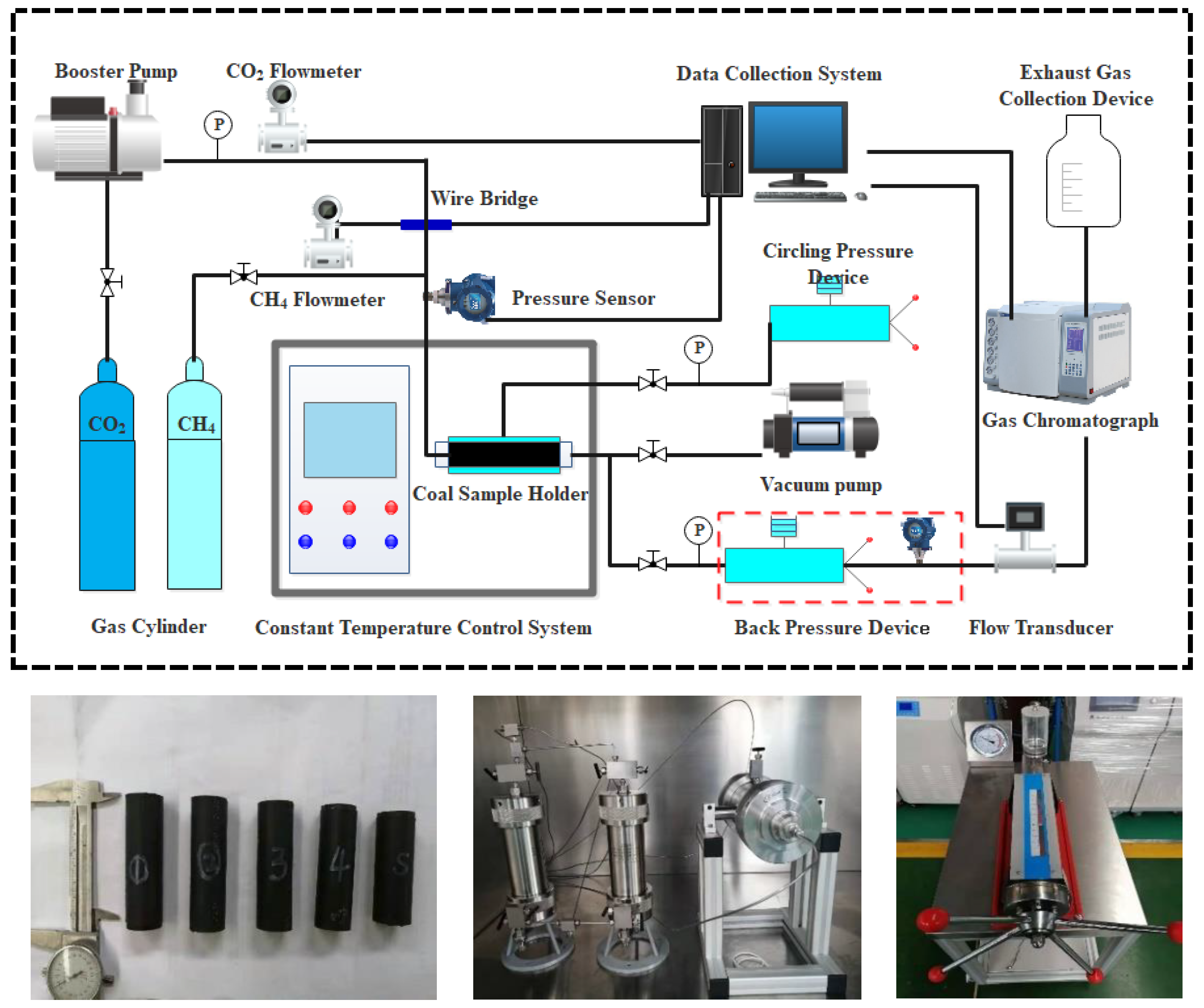
The experimental system for displacing CH4 from the coal seam by injecting CO2 is composed of CH4, a CO2 injection system, a temperature control system, a core holder, a pressure control system, a data acquisition system, and a gas collection system. The experimental setup is shown in Figure 1. The CO2 injection system was pressurized using a booster pump with a maximum pressure of 15 MPa. The temperature control unit used a constant-temperature control box to adjust the ambient temperature of the holder. The instantaneous flows and cumulative flows of CH4 and CO2 were measured using a mass flowmeter. The data acquisition system collected the flow and pressure information in the injection process, the confining pressure of the holder, the back pressure of the outlet, and the flow and concentration of the outlet mixed gas. The gas acquisition system measured the instantaneous flow and cumulative flow of the mixed gas using a flow meter, and the concentration of the mixed gas was analyzed by gas chromatography [39].
- (3)
- Experimental procedure
- Vacuuming: The inlet stop valve was closed, and the vacuum pump was connected to the sample holder at the outlet. The outlet stop valve and vacuum pump were opened for 5–6 h.
- Setting confining pressure: The valve was closed at the outlet. The holder was applied with a confining pressure of 8.0 MPa.
- CH4 adsorption equilibrium: The CH4 cylinder was opened to set to a pressure of 1.5 MPa while opening the inlet valve. To ensure that the coal sample fully adsorbed the CH4, the adsorption time was more than 24 h, and the changes in flow and pressure were monitored during the adsorption process.
- CO2 injection: The CH4 intake valve was closed, the CO2 intake valve was opened, and the pressure was adjusted to the target value. After the pressure was balanced at both ends, the back pressure valve was adjusted, and the flow of the discharged gas was monitored and collected.
- Gas analysis: The outlet mixed gas was analyzed by gas chromatography.
- Pressure relief: The intake valve was closed. The internal pressure of the gripper was released by adjusting the back-pressure valve. The next set of tests were performed after the pressure was released.
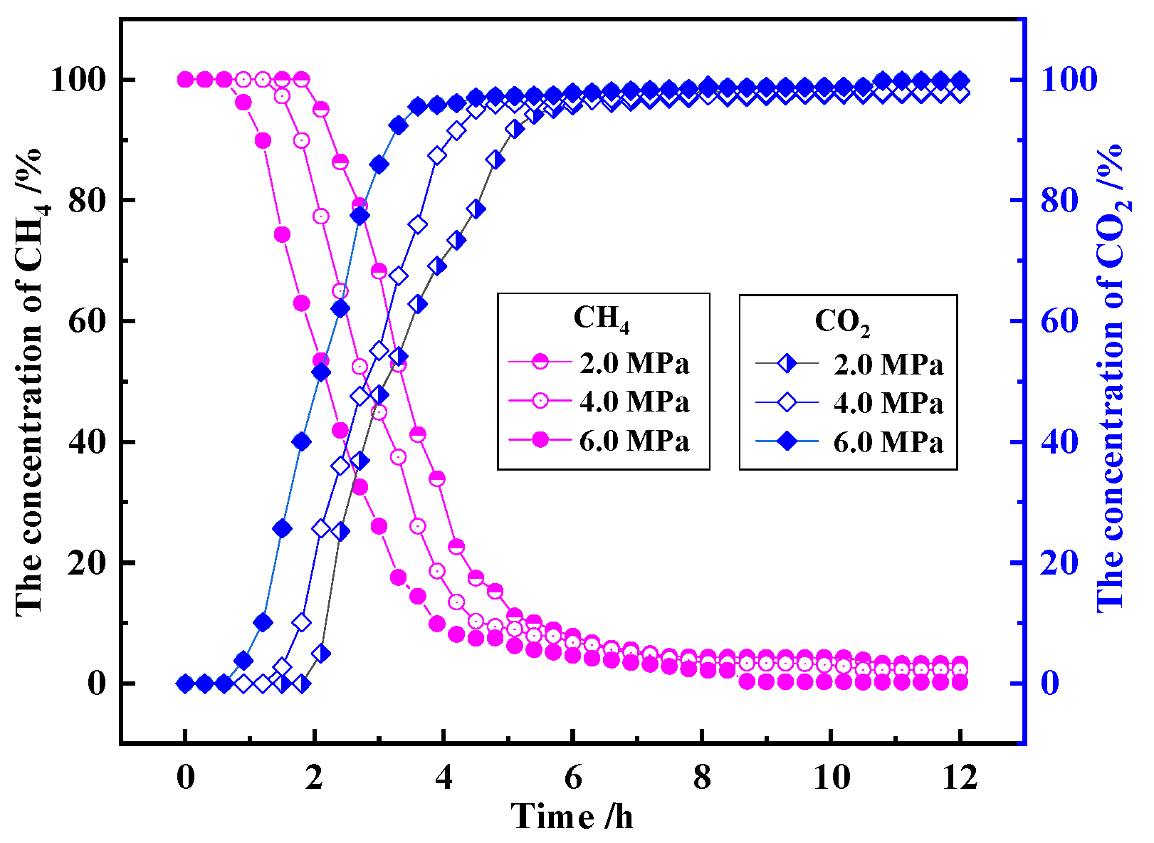
With the increasing injection of CO2 gas, CO2 seeped from coal fractures and diffused into the coal matrix pores. Finally, CO2 broke through the coal sample, and the concentration of CO2 gradually increased, while the concentration of CH4 gas began to decrease. Because the coal adsorption capacity to CO2 was stronger than CH4, CO2 competed with CH4 to adsorb on the pore surface, replaced the adsorbed CH4 on the inner surface of the coal pore, and converted it into free CH4. The migration and evolution process of CH4 went through desorption–diffusion–seepage under the action of concentration and pressure gradient, then diffused and seeped from coal pores and coal fractures to the coal surface. The concentration changes of CH4 and CO2 are shown in Figure 2. The higher the pressure, the faster the decrease in the CH4 concentration. When the concentration of CH4 decreased to 5%, the injection pressures of 6.0 MPa, 4.0 MPa, and 2.0 MPa corresponded to the corresponding times of CH4 change 3.8 h, 4.5 h, 5.1 h, respectively. Injection pressure also had a positive effect on the CO2 concentration. When the concentration of CO2 was increased to 95%, the corresponding times of CO2 change were 3.5 h, 4.5 h, and 5.5 h at pressures of 6.0 MPa, 4.0 MPa, and 2.0 MPa, respectively. The cumulative injection amount of CO2 was larger at higher pressures. A greater seepage force was provided by a higher injection pressure. Higher pressure provided a driving force for CH4 migration in the coal sample and improved the sweep efficiency.
According to the experimental results in Table 2, the CH4 production rates of coal samples under different pressures (2.0 MPa, 4.0 MPa, and 6.0 MPa) were 43.6%, 54.3%, and 70.7%, respectively. The CH4 production rate is expressed as the output volume/injection volume. With the increase in pressure, the CH4 production rate increased by 24.4% and 61.9%, respectively. The displacement ratios (CO2 storage volume/CH4 production volume) of CH4 in the coal samples injected at different pressures were 3.85, 3.15, and 2.45, respectively. As the pressure increased, the displacement ratios decreased by 18.2% and 36.4%, respectively, and the sweep efficiency promoted by 12.5% and 62.2%, respectively.
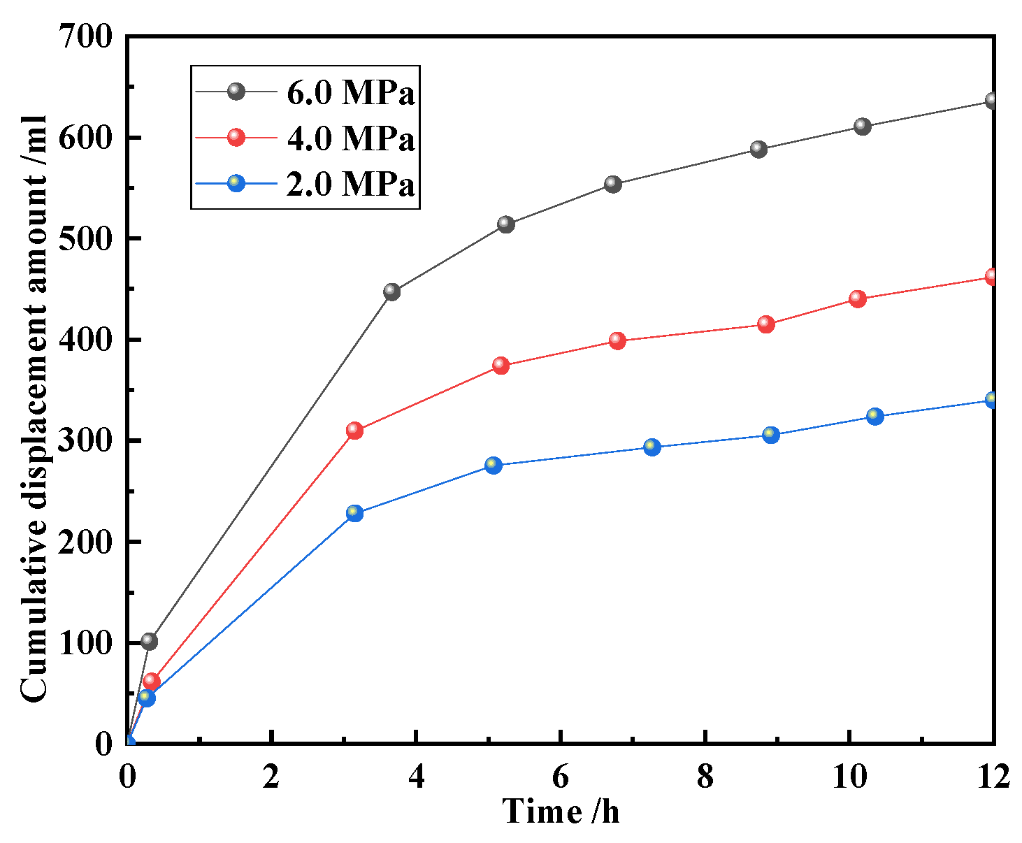
Figure 3 shows the change in the cumulative displacement of CH4 under different pressure conditions. In the early stage, cumulative growth showed a linear trend. Then, it slowly rose. The cumulative displacement increased with an increase in displacement pressure. The CO2 diffused from the pore fractures to the micropores and competed with CH4. The diffusion velocity was much smaller than the seepage velocity. A large amount of CO2 was discharged from the coal before it entered the pores. As a result, the storage and output rates tended to flatten. Therefore, the adsorption and storage of CO2 in the coal seam was faster and more effective in the early stages of displacement. The sweep effect tends to be stable, while the CH4 production rate becomes small in later stages.
In the initial stage, the cumulative displacement of CH4 increased rapidly and exhibited a linear growth trend. After reaching the critical time, the CH4 desorption rate was smaller than the CO2 displacement volume and then reached a constant value. Therefore, the cumulative amount of CH4 displacement in the coal during the same period also changed slowly. At the beginning of the experiment, there was more free CH4, which quickly flowed out of the coal under the displacement pressure. It can be seen that the initial CH4 sweep efficiency is higher. After the critical time, the sweep efficiency gradually reached a constant value, and the concentration was stable at approximately 2.0%. With an increase in the displacement time, the adsorbed CH4 in coal accounted for the majority, and there was very little free CH4. The gas desorption rate tended to be constant, and the sweep efficiency did not change significantly.
2.3. In Situ Experiment
2.3.1. Experimental Design and System Process
This field industrial test was conducted in the return airway of the 401,101 working face in the Mengcun coal mine of Binchang mining area in Shaanxi Province. The #4 coal seam is a low metamorphic bituminous coal deposit with an average thickness of 13.0 m and an average dip angle of 3°, and it is a typical coal seam with high gas and low permeability. The predicted value of absolute gas emission in the mine is 110.5 m3/min, while the predicted value of relative gas emission is 8.1 m3/t. When gas extraction is carried out by dense drilling, problems such as high cost, long extraction time, and poor extraction effect must be overcome. To solve these problems, L-CO2 displacing coal seam CH4 technology was used to improve the efficiency of gas drainage and provide strong support for gas disaster prevention and mine safety production.
Two groups of injection holes and a group of contrast holes were designed in the L-CO2 injection test; each group designed a L-CO2 injection hole and six inspection holes. There were five contrast holes in the original area. The drilling design schematic is shown in Figure 4, and the drilling design parameters are listed in Table 3.
A process diagram of the L-CO2 injection system is shown in Figure 5. It is composed of an L-CO2 injection system, data acquisition system, gas drainage system, and borehole design. The L-CO2 injection system consists of an L-CO2 tanker, a low-temperature booster pump (with a maximum flow rate of 2000 L/h and maximum working pressure of 15.0 MPa), pressure-resistant transmission pipeline, stop valves, and relief valves. The data acquisition system includes pressure acquisition, flow acquisition, and drainage system monitoring (drainage flow, CO2 concentration, and CH4 concentration). The gas extraction system includes a gas extraction pump and extraction pipeline [40,41]. When the booster pump was used, the pipeline of the injection system was pre-cooled, and the temperature condition of the pump start was set to ≤−15 °C. In order to ensure that CO2 was kept in the liquid state during the injection process, the pressure of the booster pump was never less than 3.0 MPa.
The success or failure of the experiment was determined based on the sealing quality of the borehole. The length of sealing in L-CO2 displacing CH4 experimental drilling involves several factors such as the pressure of the sealing section, the distance of the gas discharge belt from the coal wall, and the influence of air leakage from the hole. The sealing length was determined by combining data from the actual sealing experience on site with safety factors [42,43], which ensured the safety and reliability of the experiment. The sealing lengths of the injection hole, comparison hole, and original hole were 50 m, 30 m, and 12 m, respectively. A schematic diagram of the borehole sealing is shown in Figure 6.
2.3.2. Experimental Analysis
- (1)
- Pressure changes
The L-CO2 injection tests were divided into two groups, low pressure and medium pressure. The low-pressure injection used L-CO2 storage tanks to inject directly, while the medium-pressure injection utilized the L-CO2 storage tank and booster pump. During the test, changes in the orifice pressure and extraction effect under different pressures were observed. The main technical indicators are listed in Table 4, and the pressure trends during the injection process are shown in Figure 7.
The diagram shows that a tank injection with a maximum pressure of 2.50 MPa was used, and the pressure was maintained for approximately 90–110 min. When the system was cooled by gas injection for a certain time, liquid CO2 was injected, and it reached its maximum value. With continuous injection, the pressure fluctuated around 1.5–1.6 MPa and decreased slowly. L-CO2 was supercharged by a booster pump during medium pressure injection. Figure 7a shows that the pressure reached 2.60 MPa after 17 min, and the pressure continued rising after approximately 40 min. It reached a maximum value of 3.2 MPa and fluctuated around 3.0 MPa. The fluctuation time was approximately 25 min, after which the pressure decreased rapidly. Figure 7b shows that the pressure reached a maximum value of 3.20 MPa rapidly, fluctuated around 3.2 MPa for approximately 71 min, and then decreased when the pump stopped.
The pressure increase rate of the low-pressure injection was approximately 0.066–0.075 MPa/min, and that of the medium pressure injection was approximately 0.135–0.186 MPa/min. The pressure reduction rate during the low-pressure injection was approximately 0.013 MPa/min, and that of the medium-pressure injection was approximately 0.025–0.031 MPa/min. The increase rate and reduction rate of the medium-pressure injection were larger than those of the low-pressure injection. The effective injection time was approximately 100 min when the tank was used, while the effective injection time of the tank and booster pump was approximately 65 min. When the booster pump was used for injection, the effective injection time was reduced by 35 min. The increased displacement pressure improved the time efficiency, and the increase in pressure was beneficial to gas diffusion.
- (2)
- Analysis of displacement process
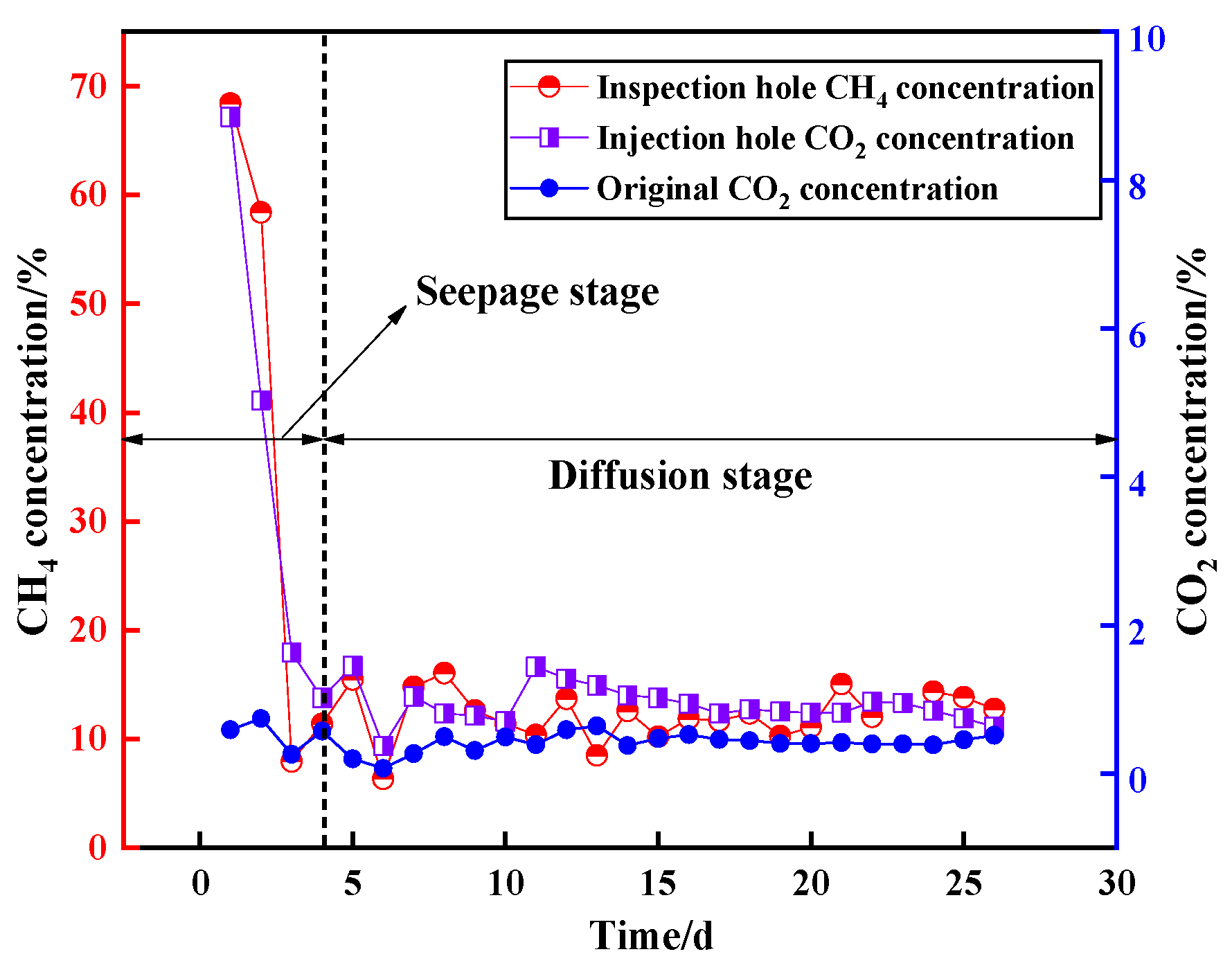
The relationship between the concentrations of CH4 and CO2 is shown in Figure 8. During the injection process, the change trend of the CH4 concentration is consistent with that of the CO2 concentration. The entire process can be divided into two stages: seepage and diffusion. The pressure gradient generated during the L-CO2 injection and phase transition in seepage stage. The free CH4 was driven out along the fractured channel. The initial concentration was high but decreased rapidly. At the same time, the displacement effect on the free gas was obvious, and the gas concentration was high in the initial stage. The diffusion stage occurred after the vaporization of L-CO2 in the hole, and the concentration difference was generated by the gas. Adsorption CH4 was replaced by CO2 during diffusion. At that time, the gas diffused into the pores of the coal matrix through the concentration difference, and the displacement and desorption of the free CH4 in the coal matrix and the adsorbed CH4 were carried out. With the diffusion of CO2, the displacement effect on a certain range of coal was gradually reduced, and the gas concentration also declined. When the concentration of CO2 was approximately the same as that of the original area, this stage has ended. The CO2 in the coal seam still played a role in displacement, and the gas remained at a higher concentration relative to the original area.
- (3)
- Seepage diffusion range for CO2
The temperatures 3 m and 5 m from injection hole were measured by an infrared thermal imager under the medium pressure injection. The temperature decreased slowly as the distance from injection hole increased. As shown in Figure 9, when the pressure was between 2.5 MPa and 3.0 MPa, the CO2 3 m away from the injection hole was in the liquid phase, while that 5 m away was at the critical point of liquid–gas phase. It was concluded that the L-CO2 phase transition range and seepage range is less than 5 m.
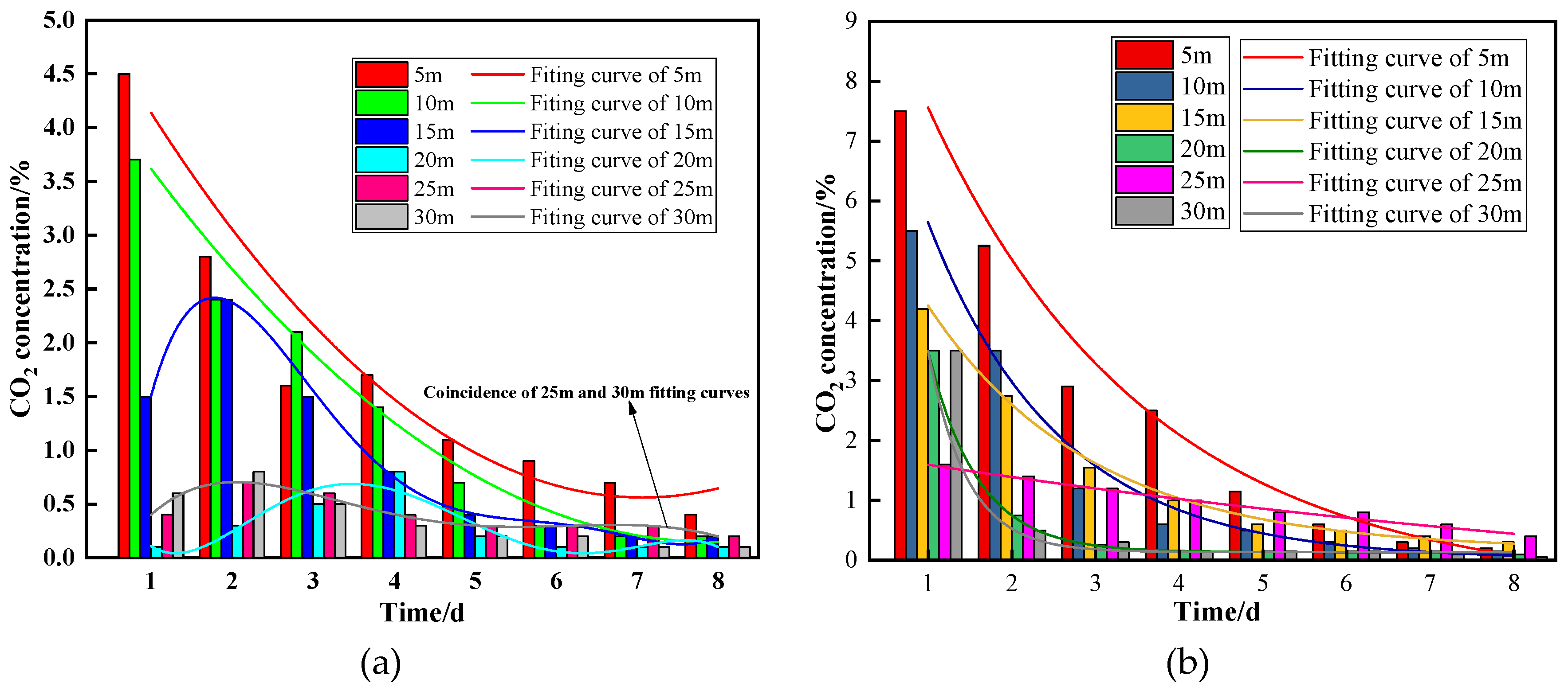
As shown in Figure 10, the CO2 concentration changes in the inspection holes under low- and medium-pressure injections were investigated at different distances. The curve fitting formula for the CO2 concentration change can be expressed as . The fitting parameters are listed in Table 5 and Table 6. At low-pressure injection, the R2 values of Figure 10a at 5 m and 10 m from the injection hole were 0.9679 and 0.9742, respectively. The polynomial was used to fit 15 m to 30 m fitting curve, and the R2 values of 15 m to 30 m were 0.9946, 0.9503, 0.9971 and 0.9970, respectively. After 15 m to 30 m, due to the uneven distribution of coal seam porosity and permeability, the pressure gradient of CO2 during low-pressure injection is small; the concentration difference is small at the initial stage of diffusion, and the diffusion rate of CO2 seepage is slow. With the passage of diffusion time and the increase in the concentration difference, the CO2 concentration detected from 15 m to 30 m has an increasing trend compared with the initial stage, and gradually decreased with the decrease in concentration difference in the later stage.
For the ranges of 15 m, 20 m, 25 m, and 30 m from the injection hole, the concentration of CO2 first increased and then decreased. Because the pressure gradient between the injection hole and the investigation hole was relatively small under low-pressure injection, the CO2 seepage tended to be slow. With an increase in the total injection volume, the diffusion range and amount of CO2 gradually increased under the effect of the CO2 concentration gradient. In the medium-pressure injection, the variation trend of CO2 concentration in each inspection hole in Figure 10b was in line with the exponential decreasing trend. The 25 m distance curve is slightly different from the other curves. The difference in the permeability and inhomogeneity of coal fracture development on both sides of the injection hole affected the seepage diffusion of CO2. Under the medium-pressure injection, the CO2 seepage diffusion velocity and concentration were higher. The original contrast-hole CO2 concentration was 0.43%. The diffusion range of CO2 under low-pressure injection was 20–25 m, while under medium pressure injection it was 25–30 m. Therefore, a higher displacement pressure can effectively promote the displacement of CH4 by L-CO2.
- (4)
- Analysis of the displacement effect
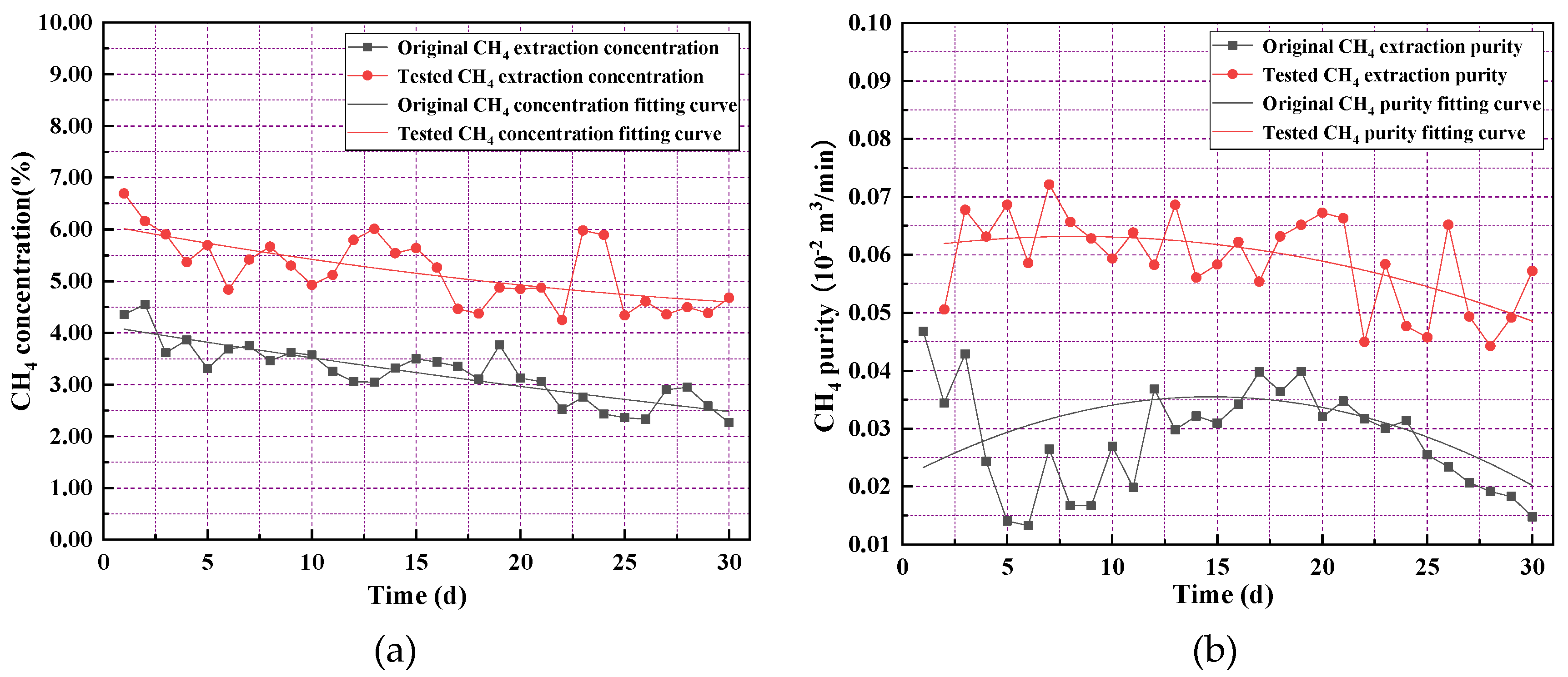
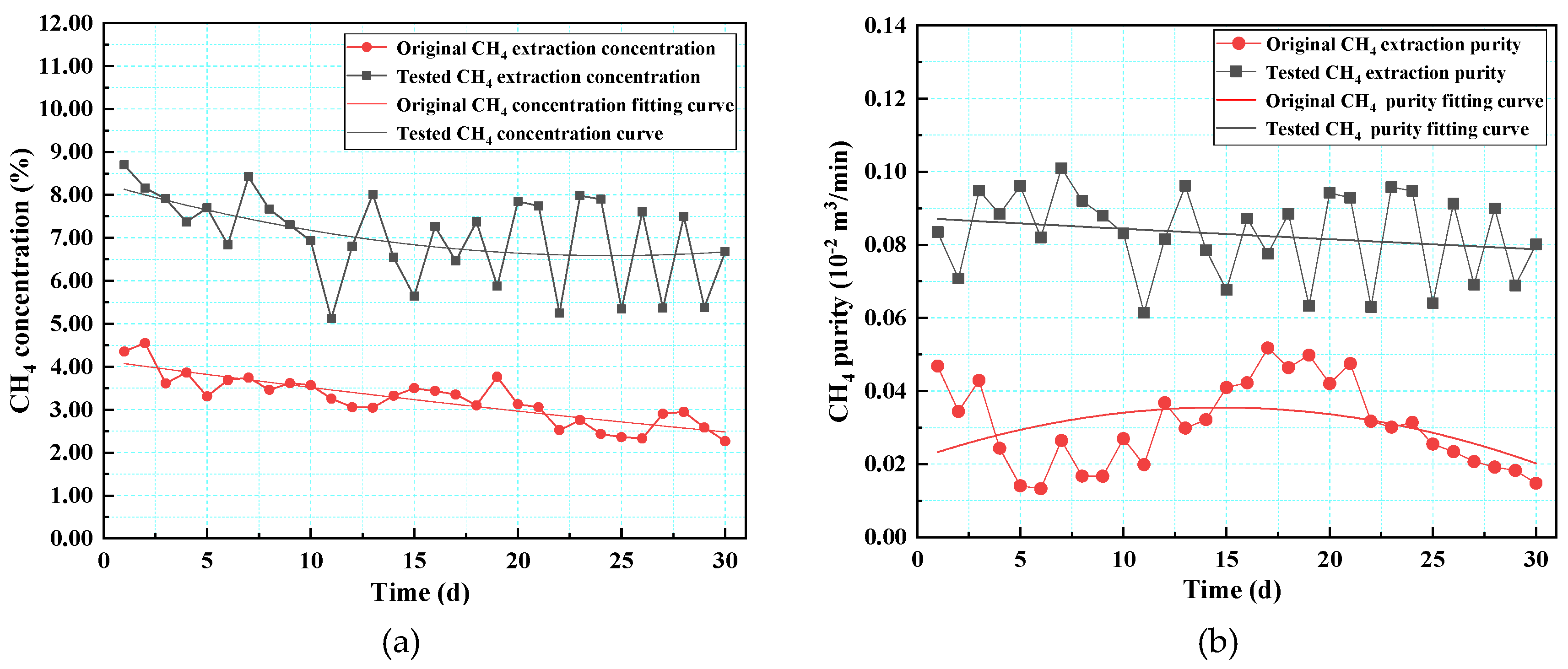
The average gas drainage concentration and drainage purity during low-pressure and medium-pressure injections are presented in Figure 11 and Figure 12, respectively. The average gas extraction concentration in the original area was 3.23%, and the average gas extraction purity was 0.00028 m3/min. The average gas drainage concentration of the monitoring borehole during low-pressure injection was 5.19%, and the average gas drainage purity was 0.00059 m3/min. The average gas extraction concentration during low-pressure injection was 1.61 times that of the original area, and the average gas extraction purity was 2.08 times that of the original area. The average gas extraction concentration of the monitoring borehole during medium-pressure injection was 7.02%, and the average gas extraction purity was 0.00083 m3/min. The average gas extraction concentration during medium-pressure injection was 2.17 times that of the original area, and the average gas extraction purity was 2.94 times that of the original area. The medium-pressure injection of average gas extraction concentration was 1.35 times of that of the low-pressure injection, and the medium-pressure injection of average gas extraction purity was 1.41 times of that of the low-pressure injection. The medium-pressure injection was more efficient.
- (5)
- Comparison of sweep efficiency
In the field test, to analyze the displacement effect under different pressures, the sweep efficiency was determined by comparing the total amount of displacement gas.
where represents gas drainage efficiency, and are the gas drainage flow and gas drainage concentration after displacement, respectively; and are the gas drainage flow and gas drainage concentration before displacement, respectively.
The low- and medium-pressure gas drainage data can be calculated using Formula (5). The gas extraction efficiency in low-pressure injection was 52.4%, while the gas extraction efficiency in medium-pressure injection was 66.0%. The sweep efficiency of the medium-pressure injection (average pressure—2.8 MPa) was 26% higher than that of the low-pressure injection (average pressure—1.4 MPa).
In the displacement experiment, the variation law of CH4 and CO2 concentration under different pressure injection conditions was obtained, and the variation law of the concentration showed the rule of “alternating growth and decline”. At the same time, the injection pressure has a positive effect in the experimental process: the higher the pressure, the higher the displacement efficiency, and the greater the cumulative displacement. Combined with the laboratory results of CO2 displacement coal seam CH4, in the field test of liquid CO2 displacement coal seam CH4 under different pressure conditions, the injection pressure also has a positive effect on the improvement of displacement efficiency, influence range and gas extraction effect. Therefore, a CO2 displacement experiment in the laboratory provides research foundation and theoretical basis for field tests.
3. Conclusions
- (1)
- The CH4 production rates under different pressures (2.0 MPa, 4.0 MPa, and 6.0 MPa) were 43.6%, 54.3%, and 70.7%, respectively. With the increase in pressure, the CH4 production rate increased by 24.4% and 61.9%, respectively. The displacement ratios of CH4 in the coal samples injected with different pressures were 3.85, 3.15, and 2.45. As the pressure increased, the displacement ratios decreased by 18.2% and 36.4%, respectively, and the sweep efficiency increased by 12.5% and 62.2%, respectively. Increasing the pressure improved the CH4 sweep efficiency and decreased the displacement ratio.
- (2)
- The maximum pressure of the low-pressure injection was 1.52 MPa, while the maximum pressure of the medium-pressure injection was 3.16 MPa. The pressure was 2.1 times that of the low-pressure injection. The pressure rise rate was 2.82 times that of low-pressure injection, and the pressure drop rate was 1.32 times that of the low-pressure injection. (3) Through a comparative analysis of the change trend of the CH4 concentration and CO2 concentration in the observation hole, it was determined that the change trend remained the same. The process of L-CO2 displacing gas can be roughly divided into two stages: the seepage stage and the diffusion stage. In the seepage stage, CO2 had a more obvious driving effect on free gas, and the gas concentration was relatively high in the initial stage. In the diffusion stage, CO2 played a major role in the displacement and desorption of adsorbed gas, and the gas concentration gradually decreased. A higher displacement pressure effectively promoted the displacement of CH4 by L-CO2. The diffusion range of CO2 under the low-pressure injection was 20–25 m, while under medium-pressure injection it was 25–30 m.
- (3)
- Inspection of the gas extraction field revealed that the concentration of CH4 extracted increased from 3.23% to 5.19% after the low-pressure injection of L-CO2 into the coal seam, increasing the concentration of gas extracted by 0.61 times. The pure flow of gas extracted increased from 0.028 m3/min to 0.059 m3/min, increasing the pure flow of gas extracted by 1.08 times. The concentration of CH4 extracted increased from 3.23% to 7.02% after the medium-pressure injection of L-CO2 into the coal seam, increasing the concentration of gas extracted by 1.17 times. The pure flow of gas extracted increased from 0.028 m3/min to 0.083 m3/min, increasing the pure flow of gas extracted by 1.94 times. The average gas drainage concentration of the medium-pressure injection was 1.35 times that of the low-pressure injection, and the average gas drainage scalar medium-pressure injection was 1.41 times that of low-pressure injection. The sweep efficiency of the medium-pressure injection (average pressure—2.8 MPa) was 26% higher than that of the low-pressure injection (average pressure—1.4 MPa). The overall efficiency of the medium-pressure injection was much higher.
Through this test, the displacement technology of coal seam CH4 by injection of L-CO2 proved to significantly improve gas drainage efficiency. An increase in pressure is beneficial for improving the sweep efficiency of L-CO2. This field test only carried out displacement tests under two pressure conditions, and the experimental results have important significance for field gas drainage. Due to the influence of various mine production factors, it is impossible to carry out more displacement tests under pressure conditions and different flow conditions. As the test is difficult to implement in the field, it is still necessary to study displacement field tests under different pressure and different flow conditions in the future.
Author Contributions
Data curation: M.L. and X.C.; writing—original draft preparation: M.L., H.W. (Hu Wen) and S.F.; writing—review and editing: M.L., Z.W. and J.F.; field observation: G.W. and H.W. (Hu Wang). All authors have read and agreed to the published version of the manuscript.
Funding
This research was funded by the National Natural Science Foundation of China (grant numbers: 51974240 and 52104221).
Institutional Review Board Statement
Not applicable.
Informed Consent Statement
Not applicable.
Data Availability Statement
The experimental and computational data presented in the present paper are available from the corresponding author upon request.
Acknowledgments
We thank Mengcun Coal Mine for providing experimental sites and the efforts of all members of the project team.
Conflicts of Interest
The authors declare no conflict of interest.
References
- Zhou, F.; Xia, T.; Wang, X.; Zhang, Y.; Sun, Y.; Liu, J. Recent developments in coal mine methane extraction and utilization in China: A review. J. Nat. Gas Sci. Eng. 2016, 31, 437–458. [Google Scholar] [CrossRef]
- Zhang, D.; Cen, X.; Wang, W.; Deng, J.; Wen, H.; Xiao, Y.; Shu, C.-M. The graded warning method of coal spontaneous combustion in Tangjiahui Mine. Fuel 2021, 288, 119635. [Google Scholar] [CrossRef]
- Chen, X.; Li, L.; Wang, L.; Qi, L. The current situation and prevention and control countermeasures for typical dynamic disasters in kilometer-deep mines in China. Saf. Sci. 2019, 115, 229–236. [Google Scholar] [CrossRef]
- Wei, G.; Wen, H.; Deng, J.; Ma, L.; Li, Z.; Lei, C.; Fan, S.; Liu, Y. Liquid CO2 injection to enhance coalbed methane recovery: An experiment and in-situ application test. Fuel 2021, 284, 119043. [Google Scholar] [CrossRef]
- Li, Z.; Wei, G.; Liang, R.; Shi, P.; Wen, H.; Zhou, W. LCO2-ECBM technology for preventing coal and gas outburst: Integrated effect of permeability improvement and gas displacement. Fuel 2021, 285, 119219. [Google Scholar] [CrossRef]
- Lin, J.; Ren, T.; Cheng, Y.; Nemcik, J.; Wang, G. Cyclic N2 injection for enhanced coal seam gas recovery: A laboratory study. Energy 2019, 188, 116115. [Google Scholar] [CrossRef]
- Durucan, S.; Shi, J.-Q. Improving the CO2 well injectivity and enhanced coalbed methane production performance in coal seams. Int. J. Coal Geol. 2009, 77, 214–221. [Google Scholar] [CrossRef]
- Wen, H.; Li, Z.; Deng, J.; Shu, C.-M.; Laiwang, B.; Wang, Q.; Ma, L. Influence on coal pore structure during liquid CO2-ECBM process for CO2 utilization. J. CO2 Util. 2017, 21, 543–552. [Google Scholar] [CrossRef]
- Qin, L.; Li, S.; Zhai, C.; Lin, H.; Zhao, P.; Shi, Y.; Bai, Y. Changes in the pore structure of lignite after repeated cycles of liquid nitrogen freezing as determined by nitrogen adsorption and mercury intrusion. Fuel 2020, 267, 117214. [Google Scholar] [CrossRef]
- Wen, H.; Cheng, X.; Chen, J.; Zhang, C.; Yu, Z.; Li, Z.; Fan, S.; Wei, G.; Cheng, B. Micro-pilot test for optimized pre-extraction boreholes and enhanced coalbed methane recovery by injection of liquid carbon dioxide in the Sangshuping coal mine. Process Saf. Environ. Prot. 2020, 136, 39–48. [Google Scholar] [CrossRef]
- Yan, F.; Lin, B.; Zhu, C.; Shen, C.; Zou, Q.; Guo, C.; Liu, T. A novel ECBM extraction technology based on the integration of hydraulic slotting and hydraulic fracturing. J. Nat. Gas Sci. Eng. 2015, 22, 571–579. [Google Scholar] [CrossRef]
- Ranathunga, A.S.; Perera, M.S.A.; Ranjith, P.G.; Zhang, X.G.; Wu, B. Super-critical carbon dioxide flow behaviour in low rank coal: A meso-scale experimental study. J. CO2 Util. 2017, 20, 1–13. [Google Scholar] [CrossRef]
- Sander, R.; Pan, Z.; Connell, L.D. Laboratory measurement of low permeability unconventional gas reservoir rocks: A review of experimental methods. J. Nat. Gas Sci. Eng. 2017, 37, 248–279. [Google Scholar] [CrossRef]
- Zou, Q.; Lin, B. Fluid–Solid Coupling Characteristics of Gas-Bearing Coal Subjected to Hydraulic Slotting: An Experimental Investigation. Energy Fuels 2018, 32, 1047–1060. [Google Scholar] [CrossRef]
- Busch, A.; Gensterblum, Y. CBM and CO2-ECBM related sorption processes in coal: A review. Int. J. Coal Geol. 2011, 87, 49–71. [Google Scholar] [CrossRef]
- Zhou, F.; Hussain, F.; Cinar, Y. Injecting pure N2 and CO2 to coal for enhanced coalbed methane: Experimental observations and numerical simulation. Int. J. Coal Geol. 2013, 116–117, 53–62. [Google Scholar] [CrossRef]
- Vishal, V. In-situ disposal of CO2: Liquid and supercritical CO2 permeability in coal at multiple down-hole stress conditions. J. CO2 Util. 2017, 17, 235–242. [Google Scholar] [CrossRef]
- Lin, J.; Ren, T.; Wang, G.; Booth, P.; Nemcik, J. Experimental investigation of N2 injection to enhance gas drainage in CO2-rich low permeable seam. Fuel 2018, 215, 665–674. [Google Scholar] [CrossRef]
- Syah, R.; Alizadeh, S.M.; Darvishzadeh, L.; Elveny, M.; Abedi, M.; Ramdan, D. Simultaneous injection of chemical agents and carbon dioxide to enhance the sweep efficiency from fractured tight core samples. Energy Rep. 2021, 7, 5639–5646. [Google Scholar] [CrossRef]
- Kumar, H.; Elsworth, D.; Mathews, J.P.; Liu, J.; Pone, D. Effect of CO2 injection on heterogeneously permeable coalbed reservoirs. Fuel 2014, 135, 509–521. [Google Scholar] [CrossRef]
- Merkel, A.; Gensterblum, Y.; Krooss, B.M.; Amann, A. Competitive sorption of CH4, CO2 and H2O on natural coals of different rank. Int. J. Coal Geol. 2015, 150–151, 181–192. [Google Scholar] [CrossRef]
- Dutka, B.; Kudasik, M.; Pokryszka, Z.; Skoczylas, N.; Topolnicki, J.; Wierzbicki, M. Balance of CO2/CH4 exchange sorption in a coal briquette. Fuel Process. Technol. 2013, 106, 95–101. [Google Scholar] [CrossRef]
- Liu, Z.; Cheng, Y.; Wang, Y.; Wang, L.; Li, W. Experimental investigation of CO2 injection into coal seam reservoir at in-situ stress conditions for enhanced coalbed methane recovery. Fuel 2019, 236, 709–716. [Google Scholar] [CrossRef]
- Kumar, H.; Elsworth, D.; Liu, J.; Pone, D.; Mathews, J.P. Optimizing enhanced coalbed methane recovery for unhindered production and CO2 injectivity. Int. J. Greenh. Gas Control 2012, 11, 86–97. [Google Scholar] [CrossRef]
- Kim, S.; Ko, D.; Mun, J.; Kim, T.-H.; Kim, J. Techno-economic evaluation of gas separation processes for long-term operation of CO2 injected enhanced coalbed methane (ECBM). Korean J. Chem. Eng. 2018, 35, 941–955. [Google Scholar] [CrossRef]
- Topolnicki, J.; Kudasik, M.; Dutka, B. Simplified model of the CO2/CH4 exchange sorption process. Fuel Process. Technol. 2013, 113, 67–74. [Google Scholar] [CrossRef]
- Mazzotti, M.; Pini, R.; Storti, G. Enhanced coalbed methane recovery. J. Supercrit. Fluids 2009, 47, 619–627. [Google Scholar] [CrossRef]
- Bai, X.; Zhang, D.; Zeng, S.; Zhang, S.; Wang, D.; Wang, F. An enhanced coalbed methane recovery technique based on CO2 phase transition jet coal-breaking behavior. Fuel 2020, 265, 116912. [Google Scholar] [CrossRef]
- Wang, J.; Liu, J.; Li, Z.; Li, H.; Zhang, J.; Li, W.; Zhang, Y.; Ping, Y.; Yang, H.; Wang, P. Synchronous injection-production energy replenishment for a horizontal well in an ultra-low permeability sandstone reservoir: A case study of Changqing oilfield in Ordos Basin, NW China. Pet. Explor. Dev. 2020, 47, 827–835. [Google Scholar] [CrossRef]
- Chen, H.; Wang, Z.; Chen, X.; Chen, X.; Wang, L. Increasing permeability of coal seams using the phase energy of liquid carbon dioxide. J. CO2 Util. 2017, 19, 112–119. [Google Scholar] [CrossRef]
- Wei, G.; Wen, H.; Deng, J.; Li, Z.; Fan, S.; Lei, C.; Liu, M.; Ren, L. Enhanced coalbed permeability and methane recovery via hydraulic slotting combined with liquid CO2 injection. Process Saf. Environ. Prot. 2021, 147, 234–244. [Google Scholar] [CrossRef]
- Vishal, V. Saturation time dependency of liquid and supercritical CO2 permeability of bituminous coals: Implications for carbon storage. Fuel 2017, 192, 201–207. [Google Scholar] [CrossRef]
- Wen, H.; Wei, G.; Ma, L.; Li, Z.; Lei, C.; Hao, J. Damage characteristics of coal microstructure with liquid CO2 freezing-thawing. Fuel 2019, 249, 169–177. [Google Scholar] [CrossRef]
- Fujioka, M.; Yamaguchi, S.; Nako, M. CO2-ECBM field tests in the Ishikari Coal Basin of Japan. Int. J. Coal Geol. 2010, 82, 287–298. [Google Scholar] [CrossRef]
- Liang, W.; Zhao, Y.; Wu, D.; Dusseault, M.B. Experiments on Methane Displacement by Carbon Dioxide in Large Coal Specimens. Rock Mech. Rock Eng. 2011, 44, 579–589. [Google Scholar] [CrossRef]
- Perera, M.S.A.; Ranjith, P.G.; Airey, D.W.; Choi, S.K. Sub- and super-critical carbon dioxide flow behavior in naturally fractured black coal: An experimental study. Fuel 2011, 90, 3390–3397. [Google Scholar] [CrossRef]
- Godec, M.; Koperna, G.; Gale, J. CO2-ECBM: A Review of its Status and Global Potential. Energy Procedia 2014, 63, 5858–5869. [Google Scholar] [CrossRef] [Green Version]
- Zhang, X.; Ranjith, P.G. Experimental investigation of effects of CO2 injection on enhanced methane recovery in coal seam reservoirs. J. CO2 Util. 2019, 33, 394–404. [Google Scholar] [CrossRef]
- Al-Abri, A.; Sidiq, H.; Amin, R. Mobility ratio, relative permeability and sweep efficiency of supercritical CO2 and methane injection to enhance natural gas and condensate recovery: Coreflooding experimentation. J. Nat. Gas Sci. Eng. 2012, 9, 166–171. [Google Scholar] [CrossRef]
- Wen, H.; Liu, M.; Wei, G.; Zhai, X.; Fan, S.; Cheng, X.; Wang, H.; Hao, J.; Xia, B.-W. Gas Displacement Engineering Test by Combination of Low and Medium Pressure Injection with Liquid CO2 in High Gas and Low Permeability Coal Seam. Geofluids 2020, 2020, 8840602. [Google Scholar] [CrossRef]
- Wen, H.; Wang, H.; Fan, S.; Li, Z.; Chen, J.; Cheng, X.; Cheng, B.; Yu, Z. Improving coal seam permeability and displacing methane by injecting liquid CO2: An experimental study. Fuel 2020, 281, 118747. [Google Scholar] [CrossRef]
- Fan, S.; Zhang, D.; Wen, H.; Cheng, X.; Liu, X.; Yu, Z.; Hu, B. Enhancing coalbed methane recovery with liquid CO2 fracturing in underground coal mine: From experiment to field application. Fuel 2021, 290, 119793. [Google Scholar] [CrossRef]
- Zhao, W.; Cheng, Y.; Pan, Z.; Wang, K.; Liu, S. Gas diffusion in coal particles: A review of mathematical models and their applications. Fuel 2019, 252, 77–100. [Google Scholar] [CrossRef]
Figure 1.
The experimental system diagram of CO2 displacement coal seam CH4.

Figure 2.
The CH4 and CO2 concentration changes under different pressures.

Figure 3.
The curve of CH4 cumulative displacement.

Figure 4.
Schematic diagram of test borehole layout.

Figure 5.
Process diagram of L-CO2 injection system.

Figure 6.
The sealing lengths of injection hole and inspection hole (a) The sealing length of injection hole and (b) The sealing length of inspection hole.
Figure 6.
The sealing lengths of injection hole and inspection hole (a) The sealing length of injection hole and (b) The sealing length of inspection hole.

Figure 7.
The pressure change trend during injection (a) The first injection process and (b) The second injection process.
Figure 7.
The pressure change trend during injection (a) The first injection process and (b) The second injection process.

Figure 8.
Relationship between CH4 concentration and CO2 concentration change.

Figure 9.
Temperature–pressure variation curves.

Figure 10.
The change in CO2 concentration in inspection hole (a) The change of CO2 concentration during low-pressure injection and (b) The change of CO2 concentration during medium-pressure injection.
Figure 10.
The change in CO2 concentration in inspection hole (a) The change of CO2 concentration during low-pressure injection and (b) The change of CO2 concentration during medium-pressure injection.

Figure 11.
Average gas drainage concentration and drainage purity during low-pressure injection (a) Average gas drainage concentration and (b) Average gas drainage purity.
Figure 11.
Average gas drainage concentration and drainage purity during low-pressure injection (a) Average gas drainage concentration and (b) Average gas drainage purity.

Figure 12.
Average gas drainage concentration and drainage purity during medium-pressure injection (a) Average gas drainage concentration and (b) Average gas drainage purity.
Figure 12.
Average gas drainage concentration and drainage purity during medium-pressure injection (a) Average gas drainage concentration and (b) Average gas drainage purity.


Table 1.
The main parameters of displacement experiment.
| Numbering | Size of Coal Sample (mm) | CH4 Adsorption Pressure (MPa) | CH4 Adsorption Time (h) | Confining Pressure (MPa) | CO2 Injection Pressure (MPa) | Back Pressure (MPa) | Temperature (°C) |
|---|---|---|---|---|---|---|---|
| 1# | 25.1 × 60.0 | 1.0–2.0 | 16–24 | 8 | 2.0–3.0 | 1.0–1.5 | 30 |
| 2# | 24.9 × 61.0 | 1.0–2.0 | 16–24 | 8 | 4.0–5.0 | 2.0–3.0 | 30 |
| 3# | 25.0 × 59.0 | 1.0–2.0 | 16–24 | 8 | 6.0–7.0 | 4.0–5.0 | 30 |
Table 2.
The experimental results of displacement of CH4 by CO2.
| Order Number | Injection Volume/mL | Injection Pressure/MPa | Output Volume/mL | CO2 Storage/mL | Replacement Ratio | Sweep Efficiency/% | ||
|---|---|---|---|---|---|---|---|---|
| CH4 | CO2 | CH4 | CO2 | |||||
| 1 | 779 | 4370 | 2.0 | 340 | 3060 | 1310 | 3.85 | 43.6 |
| 2 | 851 | 5192 | 4.0 | 462 | 3738 | 1454 | 3.15 | 54.3 |
| 3 | 900 | 6220 | 6.0 | 636 | 4664 | 1556 | 2.45 | 70.7 |
Table 3.
Drilling design parameter table of L-CO2 injection system.
| Boreholes | Depth (m) | Orientation (°) | Dip Angle (°) | Aperture (mm) | Sealing Length (m) |
|---|---|---|---|---|---|
| YZ | 120 | 90 | 0.5–1 | 133 | 50 |
| K1–K6 | 120 | 90 | 0.5–1 | 133 | 30 |
| D1–D5 | 120 | 90 | 0–0.5 | 133 | 12 |
Table 4.
Main technical indicators of L-CO2 injection.
| Serial Number | Boost Time of Pressure/min | Pressure Fluctuation Range/MPa | Pressure Fluctuation time/min | Maximum Pressure/MPa | Cumulative Injection Volume/m3 |
|---|---|---|---|---|---|
| 1 | 23 | 1.3–1.6 | 110 | 1.52 | 5.9 |
| 2 | 17 | 2.5–3.2 | 60 | 3.16 | 5.8 |
Table 5.
The fitting parameters of CO2 concentration during low-pressure injection.
| y0 | A | B | R2 | Distance/m | |
|---|---|---|---|---|---|
| y1 | 0.51 | 6.56 | −0.51 | 0.9679 | 5 |
| y2 | −0.53 | 5.55 | −0.28 | 0.9742 | 10 |
Table 6.
The fitting parameters of CO2 concentration during medium-pressure injection.
| y0 | A | B | R2 | Distance/m | |
|---|---|---|---|---|---|
| y1 | −0.49 | 11.75 | −0.38 | 0.9879 | 5 |
| y2 | 0.02 | 10.69 | −0.64 | 0.9737 | 10 |
| y3 | 0.17 | 6.85 | −0.52 | 0.9958 | 15 |
| y4 | 0.14 | 18.40 | −1.70 | 0.9997 | 20 |
| y5 | −1.15 | 2.97 | −0.08 | 0.9818 | 25 |
| y6 | 0.14 | 28.92 | −2.15 | 0.9965 | 30 |
Publisher’s Note: MDPI stays neutral with regard to jurisdictional claims in published maps and institutional affiliations. |
© 2022 by the authors. Licensee MDPI, Basel, Switzerland. This article is an open access article distributed under the terms and conditions of the Creative Commons Attribution (CC BY) license (https://creativecommons.org/licenses/by/4.0/).
Share and Cite
MDPI and ACS Style
Liu, M.; Wen, H.; Fan, S.; Wang, Z.; Fei, J.; Wei, G.; Cheng, X.; Wang, H. Experimental Study of CO2-ECBM by Injection Liquid CO2. Minerals 2022, 12, 297. https://0-doi-org.brum.beds.ac.uk/10.3390/min12030297
AMA Style
Liu M, Wen H, Fan S, Wang Z, Fei J, Wei G, Cheng X, Wang H. Experimental Study of CO2-ECBM by Injection Liquid CO2. Minerals. 2022; 12(3):297. https://0-doi-org.brum.beds.ac.uk/10.3390/min12030297
Chicago/Turabian StyleLiu, Mingyang, Hu Wen, Shixing Fan, Zhenping Wang, Jinbiao Fei, Gaoming Wei, Xiaojiao Cheng, and Hu Wang. 2022. "Experimental Study of CO2-ECBM by Injection Liquid CO2" Minerals 12, no. 3: 297. https://0-doi-org.brum.beds.ac.uk/10.3390/min12030297
Note that from the first issue of 2016, this journal uses article numbers instead of page numbers. See further details here.